EP2602915A2 - Coupelle pour stator avec isolation de moteur à rotor extérieur - Google Patents
Coupelle pour stator avec isolation de moteur à rotor extérieur Download PDFInfo
- Publication number
- EP2602915A2 EP2602915A2 EP12188636.0A EP12188636A EP2602915A2 EP 2602915 A2 EP2602915 A2 EP 2602915A2 EP 12188636 A EP12188636 A EP 12188636A EP 2602915 A2 EP2602915 A2 EP 2602915A2
- Authority
- EP
- European Patent Office
- Prior art keywords
- wiring
- mounting cap
- stator
- motor
- stator core
- Prior art date
- Legal status (The legal status is an assumption and is not a legal conclusion. Google has not performed a legal analysis and makes no representation as to the accuracy of the status listed.)
- Granted
Links
- 238000000576 coating method Methods 0.000 claims description 9
- 230000037361 pathway Effects 0.000 claims description 8
- 239000011248 coating agent Substances 0.000 claims description 7
- 239000000463 material Substances 0.000 claims description 7
- 239000000843 powder Substances 0.000 claims description 5
- 229910052782 aluminium Inorganic materials 0.000 claims description 4
- XAGFODPZIPBFFR-UHFFFAOYSA-N aluminium Chemical compound [Al] XAGFODPZIPBFFR-UHFFFAOYSA-N 0.000 claims description 4
- 229920003002 synthetic resin Polymers 0.000 claims description 3
- 239000000057 synthetic resin Substances 0.000 claims description 3
- 238000010276 construction Methods 0.000 claims description 2
- 238000006073 displacement reaction Methods 0.000 claims description 2
- 239000007769 metal material Substances 0.000 claims 1
- XEEYBQQBJWHFJM-UHFFFAOYSA-N Iron Chemical compound [Fe] XEEYBQQBJWHFJM-UHFFFAOYSA-N 0.000 description 6
- 238000005406 washing Methods 0.000 description 6
- 230000005291 magnetic effect Effects 0.000 description 5
- 229910052751 metal Inorganic materials 0.000 description 5
- 239000002184 metal Substances 0.000 description 5
- 238000000034 method Methods 0.000 description 4
- RYGMFSIKBFXOCR-UHFFFAOYSA-N Copper Chemical compound [Cu] RYGMFSIKBFXOCR-UHFFFAOYSA-N 0.000 description 3
- 229910052742 iron Inorganic materials 0.000 description 3
- 239000010410 layer Substances 0.000 description 3
- 230000008569 process Effects 0.000 description 3
- 229910000831 Steel Inorganic materials 0.000 description 2
- 239000003302 ferromagnetic material Substances 0.000 description 2
- 238000003780 insertion Methods 0.000 description 2
- 230000037431 insertion Effects 0.000 description 2
- 238000009413 insulation Methods 0.000 description 2
- 238000004519 manufacturing process Methods 0.000 description 2
- 239000010959 steel Substances 0.000 description 2
- 238000004804 winding Methods 0.000 description 2
- 238000004026 adhesive bonding Methods 0.000 description 1
- 238000013459 approach Methods 0.000 description 1
- 229910052802 copper Inorganic materials 0.000 description 1
- 239000010949 copper Substances 0.000 description 1
- 230000003247 decreasing effect Effects 0.000 description 1
- 230000001419 dependent effect Effects 0.000 description 1
- 238000009826 distribution Methods 0.000 description 1
- 230000000694 effects Effects 0.000 description 1
- 230000005294 ferromagnetic effect Effects 0.000 description 1
- 238000010348 incorporation Methods 0.000 description 1
- 238000002955 isolation Methods 0.000 description 1
- 238000003475 lamination Methods 0.000 description 1
- 230000000670 limiting effect Effects 0.000 description 1
- 238000005360 mashing Methods 0.000 description 1
- 230000007246 mechanism Effects 0.000 description 1
- 238000012986 modification Methods 0.000 description 1
- 230000004048 modification Effects 0.000 description 1
- 230000036961 partial effect Effects 0.000 description 1
- 230000002829 reductive effect Effects 0.000 description 1
- 229920005989 resin Polymers 0.000 description 1
- 239000011347 resin Substances 0.000 description 1
- 230000000717 retained effect Effects 0.000 description 1
- 230000035939 shock Effects 0.000 description 1
- 239000002356 single layer Substances 0.000 description 1
- 239000007787 solid Substances 0.000 description 1
- 238000003466 welding Methods 0.000 description 1
Images


Classifications
-
- H—ELECTRICITY
- H02—GENERATION; CONVERSION OR DISTRIBUTION OF ELECTRIC POWER
- H02K—DYNAMO-ELECTRIC MACHINES
- H02K3/00—Details of windings
- H02K3/46—Fastening of windings on the stator or rotor structure
- H02K3/52—Fastening salient pole windings or connections thereto
- H02K3/521—Fastening salient pole windings or connections thereto applicable to stators only
- H02K3/522—Fastening salient pole windings or connections thereto applicable to stators only for generally annular cores with salient poles
-
- H—ELECTRICITY
- H02—GENERATION; CONVERSION OR DISTRIBUTION OF ELECTRIC POWER
- H02K—DYNAMO-ELECTRIC MACHINES
- H02K1/00—Details of the magnetic circuit
- H02K1/06—Details of the magnetic circuit characterised by the shape, form or construction
- H02K1/12—Stationary parts of the magnetic circuit
- H02K1/18—Means for mounting or fastening magnetic stationary parts on to, or to, the stator structures
- H02K1/187—Means for mounting or fastening magnetic stationary parts on to, or to, the stator structures to inner stators
-
- H—ELECTRICITY
- H02—GENERATION; CONVERSION OR DISTRIBUTION OF ELECTRIC POWER
- H02K—DYNAMO-ELECTRIC MACHINES
- H02K1/00—Details of the magnetic circuit
- H02K1/06—Details of the magnetic circuit characterised by the shape, form or construction
- H02K1/22—Rotating parts of the magnetic circuit
- H02K1/27—Rotor cores with permanent magnets
- H02K1/2786—Outer rotors
- H02K1/2787—Outer rotors the magnetisation axis of the magnets being perpendicular to the rotor axis
- H02K1/2789—Outer rotors the magnetisation axis of the magnets being perpendicular to the rotor axis the rotor consisting of two or more circumferentially positioned magnets
- H02K1/2791—Surface mounted magnets; Inset magnets
-
- H—ELECTRICITY
- H02—GENERATION; CONVERSION OR DISTRIBUTION OF ELECTRIC POWER
- H02K—DYNAMO-ELECTRIC MACHINES
- H02K7/00—Arrangements for handling mechanical energy structurally associated with dynamo-electric machines, e.g. structural association with mechanical driving motors or auxiliary dynamo-electric machines
- H02K7/14—Structural association with mechanical loads, e.g. with hand-held machine tools or fans
-
- H—ELECTRICITY
- H02—GENERATION; CONVERSION OR DISTRIBUTION OF ELECTRIC POWER
- H02K—DYNAMO-ELECTRIC MACHINES
- H02K2203/00—Specific aspects not provided for in the other groups of this subclass relating to the windings
- H02K2203/06—Machines characterised by the wiring leads, i.e. conducting wires for connecting the winding terminations
Definitions
- the present invention relates generally to an electric motor for use in a machine. More specifically, the present invention concerns an electric motor that includes a rotor, an insulated stator, and a mounting cap.
- an electric motor may be used to cause rotation of the washer basket to agitate the clothing contained therein.
- an electric motor may be used to cause rotation of the washer basket to agitate the clothing contained therein.
- an electric motor includes a stator positioned at least in part radially inside a rotor.
- An electric motor having such a configuration is commonly referred to as an outer rotor motor or external rotor motor, although other names may be used.
- the rotor is typically coupled to the washer basket, whereas the stator is fixed to a tub mounting hub that is coupled to a stationary washer outer tub. To avoid potential electrical shock of the user, the stator is mounted in such a manner that it is electrically isolated from the tub.
- the stator of an outer rotor motor typically includes a core and a plurality of coils.
- the core takes a generally toroidal form and is composed of a ferromagnetic metal such as iron or steel.
- the core typically includes a plurality of teeth projecting radially outwardly and defining slots therebetween.
- the coils are formed by the winding of electrically conductive wire multiple times around each tooth to at least partially fill the slots. Copper wire is commonly used due to its low electrical resistivity.
- the rotor of an outer rotor motor typically includes a shaft, a support structure coupled to the shaft, and a plurality of permanent magnets supported by the support structure so that they circumscribe the stator in a spaced relationship.
- the ferromagnetic material of the core is energized to form a plurality of magnetic fields corresponding to the teeth.
- These stator magnetic fields interact with the magnetic fields produced by the permanent magnets of the rotor to induce relative rotation between the rotor and stator. The direction of each magnetic field is dependent on the direction of the current flow around the respective tooth.
- an electric motor includes a stator having coils wound clockwise around some teeth and coils wound counter-clockwise around other teeth to produce oppositely directed magnetic fields within the same stator when the wires are exposed to a direct current.
- an outer rotor motor includes a rotor rotatable about an axis, an insulated stator spaced at least partially inside the rotor, and a mounting cap.
- the stator includes a core and wiring wound around the core.
- the mounting cap is configured to support the stator and is fixed to the stator to prevent relative rotation therebetween.
- the mounting cap is configured to facilitate routing of the wiring and includes a wiring outlet at which the wiring converges for connection to a power source.
- the mounting cap further includes mounting structure configured to fix the mounting cap to the machine, such that the stator is fixed to and supported on the machine by the mounting cap.
- incorporation of the mounting structure in the mounting cap rather than in the stator core allows the size of the stator core to be reduced and increases the ease with which the motor can be adapted for use with new mounting systems.
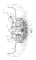
- FIG. 1 is a partial sectional bottom isometric view of a portion of a machine constructed in accordance with the principles of a preferred embodiment of the present invention, depicting a portion of a washing machine and an outer rotor electric motor that includes, among other things, a rotor, a stator, and a mounting cap;
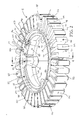
- FIG. 2 is an enlarged isometric view of the stator and mounting cap of FIG. 1 , shown from the top side;
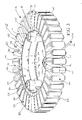
- FIG. 3 is an enlarged isometric view of the stator and mounting cap of FIG. 1 , shown from the bottom side;
- FIG. 4 is a sectional isometric view of a portion of the stator and mounting cap taken along line 4-4 of FIG. 2 , particularly depicting the mounting hole configuration and the engagement of the mounting cap with the stator core;
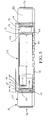
- FIG. 5 is a sectional side view of a portion of the stator and mounting cap as shown in FIG. 4 , particularly depicting the mounting hole configuration and the engagement of the mounting cap with the stator core;
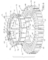
- FIG. 6 is an exploded isometric view of the stator core and mounting cap of FIGS. 1-5 , particularly depicting the alignment of the interengaging structures of the mounting cap and stator core and the radial thickness of the stator core;
- FIG. 7 is a top view of the mounting cap of FIGS. 1-6 ;
- FIG. 8 is a bottom view of the mounting cap of FIGS. 1-7 , particularly depicting the structural support ribs.
- an electric motor 10 constructed in accordance with a preferred embodiment of the present invention is depicted for use in a machine 12.
- a washing mashing having a stationary tub 14 and a rotatable washer or agitator basket (not shown).
- the motor 10 broadly includes a rotor 16 and a stator 18 spaced partially inside the rotor 16.
- the rotor 16 includes a rotatable shaft 20 connectable to the rotatable basket of the machine 12 at a machine connection end 22.
- the rotor 16 also includes a backing ring 24 located radially outwardly from the shaft 20 to circumscribe the stator 18 in a spaced relationship.
- the backing ring 24 comprises a sheet of metal wrapped five times around the outer circumference of the stator 18 so that the backing ring 24 includes five layers. (For the sake of clarity, individual layers of the backing ring 24 are not shown in FIG. 1 .)
- the metal comprises iron.
- a ring comprising a different number of layers or a single layer and/or comprising one of more of a variety of materials falls within the scope of the present invention.
- the backing ring 24 is positioned within an interconnecting element 26 that connects the backing ring 24 to a central coupler 28.
- the central coupler 28 is fixed to the shaft 20 so that the shaft 20, coupler 28, element 26, and backing ring 24 all rotate together.
- the shaft 20 has a splined end 30 that meshes with the splines 32 on the coupler 28, although other suitable means may be incorporated to rotationally fix the components to one another.
- the interconnecting element 26 includes a spoked base 34 projecting radially from the coupler 28.
- the element 26 further includes a circumferentially extending support wall 36 that projects axially from the base 34 and cooperates therewith to define a circumferentially extending channel 38 that houses the backing ring 24.
- the interconnecting element also defines a plurality of circumferentially spaced slots 40 positioned radially inwardly of the channel 38.
- the slots 40 house a plurality of permanent magnets 42 shaped such that a circumferential space 44 between the magnets 42 and the stator 18 is retained.
- the interconnecting element 26 is preferably a plastic component overmolded to the element 26 and the coupler 28; however, the principles of the present invention are equally applicable to other outer rotor motor designs.
- the rotor 16 is rotationally supported on the tub 14 by a bearing assembly 46.
- the bearing assembly 46 includes a plurality of ball bearings 48 disposed between an inner race 50 and an outer race 52, although a different bearing type or an entirely different rotation isolation mechanism could be used to similar effect without departing from the spirit of the present invention.
- a mounting cap 54 is fixed to the stator 18 to prevent relative motion therebetween and includes mounting structure configured to fix the mounting cap 54 to the machine 12, such that the stator 18 is fixed to and supported on the machine 12 by the mounting cap 54.
- the stator 18 is mounted onto the machine 12 via the fixation of the mounting cap 54 to a tub mounting hub 56.
- other means of fixing the mounting cap 54 to the machine 12, whether the machine 12 is a washing machine or another type of machine are within the scope of the present invention. Additional details of the preferred embodiments of the mounting structure will be discussed in more detail below.
- the mounting cap 54 is preferably composed of a synthetic resin material, although a different type or types of material, preferably being at least substantially electrically insulative, could be used without departing from the spirit of the present invention. Furthermore, more than one mounting cap 54 could be used, with one fixed to the top and another fixed to the bottom of the stator 18.
- the stator 18 includes a generally toroidal core 58 and a plurality of coils 60.
- the core 58 presents radially inner and outer circumferential faces 62,64 and includes a plurality of radially projecting teeth 66, each of which comprises a yoke 68, an arm 70, and a crown 72.
- the yokes 68 are interconnected and collectively present the inner circumferential face 62, while the arms 70 and crowns 72 are arcuately spaced apart to define slots 74 therebetween.
- Each tooth 66 presents an upper face 76, a lower face 78, and two side faces 80.
- the crowns 72 of teeth 66 collectively present the outer circumferential face 64, which is thus discontinuous.
- the stator core 58 preferably comprises a ferromagnetic material such as steel and is preferably a laminated structure. However, it is within the ambit of the invention for the core 58 to comprise an alternative material and be of an alternative structure. For instance, the core 58 could be integrally formed, be composed of iron, include a continuous annular base ring from which the teeth 66 project, or feature a combination of these or other variations known to one skilled in the art.
- the stator core 58 is at least partly coated with an electrically insulative coating, preferably a powder coating. More preferably, the entire stator core 58 except the inner and outer circumferential faces 62,64 is powder coated.
- an electrically insulative coating preferably a powder coating. More preferably, the entire stator core 58 except the inner and outer circumferential faces 62,64 is powder coated.
- One suitable powder coating material is available from 3M TM under the designation Scotchcast TM Electrical Resin 5555.
- the stator core 58 it is within the scope of the present invention for the stator core 58 to be insulated with other electrically insulative coatings (or low profile means that permit larger coils), as well as insulation arrangements that cover the core 58 to a lesser or greater degree than that shown.
- the coils 60 of the stator 18 comprise electrically conductive wiring 82 wound multiple times around each individual tooth 66.
- the wiring 82 preferably substantially comprises a plurality of aluminum wires, although it is within the scope of the present invention to use other types of electrically conductive wires (such as copper).
- the wires may or may not be provided with coatings. (Note that the coils 60 are shown only schematically and have been removed from all or a plurality of the teeth 66 in some figures for the sake of clarity.
- the coils 60 would be found on each tooth 66 and would comprise multiple windings of the wiring 82.
- the wiring 82 is wound around the teeth 66 in a particular pattern according to phasing of the motor 10, as will be explained further hereinbelow.
- the preferred embodiment of mounting cap 54 includes a wire routing structure 84 defining a wiring pathway 86 that projects generally from a wiring outlet 88, passes through an aperture 90, and extends arcuately along the core 58.
- the wire routing structure 84 includes an axially projecting retaining wall 92 extending arcuately above and around the upper faces 76 of the yoke portions 68 of the teeth 66, as well as an overhanging flange 94 projecting radially outwardly from the retaining wall 92.
- the wiring pathway 86 is defined about the retaining wall 92 between the overhanging flange 94 and the upper faces 76 of the yoke portions 68 of the teeth 66.
- the wiring 82 extending between the coils 60 is guided along the wiring pathway 86 by the retaining wall 92, the overhanging flange 94, and the upper faces 76 of the yoke portions 68 of teeth 66. It is not necessary that the coils 60 between which the wiring 80 is guided be adjacent. In the preferred embodiment, for instance, a first tooth 66 and an adjacent second tooth 66 are wound with wiring 82 to form respective first and second coils 60. The wiring 82 is then drawn or extended along the retaining wall 92 and below the overhanging flange 94 to a third tooth 66 that is four teeth away from the second tooth 66.
- the wiring 82 is wound around the third tooth 66 and an adjacent fourth tooth 66 to form respective third and fourth coils 60, and the process is then repeated.
- the retaining wall 92 is critical to keeping the wiring 82 from being radially displaced and the overhanging flange 94 is critical to keeping the wiring 82 from being axially displaced as the wiring 82 extends between teeth 66. It will be readily appreciated by one of ordinary skill in the art, however, that other structure capable of guiding the wiring 82 between the coils 60 could be used without departing from the teachings of the present invention. (The wiring 82 extending along the pathway 86 or between the coils 60 is not shown in the figures for the sake of clarity.)
- the preferred embodiment of the mounting cap 54 includes a hook 96 that includes a shaft 98 and an arm 100.
- the shaft 98 projects substantially axially from the wiring outlet 88, and the arm 100 extends substantially perpendicularly from the shaft 98.
- the mounting cap 54 also includes a notch 102 that extends into the wiring outlet 88.
- the wiring 82 extends from the pathway 86 into the wiring outlet 88 by passing through the wiring aperture 90, under the arm 100 and around the shaft 98 of the hook 96, and into the notch 102.
- the terminal ends of the wiring 82 are formed into bundles 104 that exit the wiring outlet 88 through a portal 106. As shown in FIG.
- the bundles 104 are joined at their ends by a crimp connector 108 that interfaces with a power source (not shown).
- a crimp connector 108 that interfaces with a power source (not shown).
- IDC insulation-displacement connector
- the mounting cap 54 preferably includes a plurality of mounting bosses 110 projecting radially inwardly relative to retaining wall 92.
- the mounting bosses are spaced equally about the inside circumference of the mounting cap 54. As will be described in further detail below, this arrangement helps distribute loads when the mounting cap 54 is fixed to the machine 12 and supports the stator 18.
- Each mounting boss 110 defines a fastener-receiving opening 112.
- a bushing 114 is preferably inserted into each of the fastener-receiving openings 112.
- the upper rim 116 of the bushing 114 aligns with an upper ledge 118 of the respective fastener-receiving opening 112, while the lower rim 120 of the bushing 114 aligns with the bottom edge 122 of the mounting cap 54 (see FIGS. 4 and 5 ).
- the mounting cap 54 it is within the scope of the present invention for the mounting cap 54 to include alternative mounting structures that may or may not incorporate the bushings 114.
- the mounting cap 54 and the stator 18 are preferably fixed relative to each other via insertion of a plurality of connecting pins 124, which protrude radially outwardly from the outer wall 126 of the mounting cap 54, into a corresponding plurality of grooves 128 formed in the inner face 62 of the core 58.
- the connecting pins 124 are heat stake pins that, upon application of appropriate heat, create a permanent bond between the mounting cap 54 and the stator 18 to prevent both relative rotational movement and relative longitudinal movement therebetween.
- the mounting cap 54 is provided with a circumferentially extending shoulder 130 that is positioned flush with the upper faces 76 of the yokes 78 of the teeth 66 when the mounting cap 54 and the stator core 58 are in an appropriate position for heat staking.
- other means of relative positioning are within the scope of the present invention. It is also within the ambit of the present invention to alternatively utilize other fixation procedures (such as snap connection, adhesive bonding, ultrasonic welding, or insertion of threaded fasteners into corresponding threaded openings) to secure the cap 54 to the core 58.
- the mounting cap 54 further includes a circumferentially extending first radial wall 132 extending radially inward from retaining wall 92 to a first edge 134, as well as a second radial wall 136 positioned slightly lower than the first radial wall132 and extending radially inward from the first edge 134 to a second edge 138.
- the outer wall 126 extends downward from the first edge 134, while an inner wall 140 extends downward from the second edge 138.
- a plurality of support ribs 142 extend between the inner wall 140 and the outer wall 126.
- a plurality of support ribs 144 is found in each of the mounting bosses 110.
- alternate means of providing structural support including use of a solid mounting cap 54 construction, are within the ambit of the present invention.
- the connecting pins 124 of the mounting cap 54 are first aligned with the grooves 128 in the inner face of the stator core 58. No clocking is necessary beyond that required to align one of the pins 124 with one of the grooves 128, with the remaining pins 124 and grooves 128 automatically falling into alignment.
- the mounting cap 54 and stator core 58 are then moved axially toward each other in such a manner that the pins 124 slide into the grooves 128. Relative axial motion ceases when the shoulder 130 is positioned flush with the upper faces 76 of the yokes 78 of the teeth 66.
- the pins 124 are then heat staked to form a permanent bond between the mounting cap 54 and the stator core 58.
- the wiring 82 is wound about the stator core 58 to form the coils 60, with the mounting cap 54 providing guidance of the wiring 82 between the teeth 66.
- a bushing 114 is inserted into each fastener-receiving opening 112, and a fastener (not shown) is received within each bushing 114.
- Each fastener is then inserted into an opening (not shown) in the tub mounting hub 56 that is fixed to the stationary tub 14.
- the mounting cap 54 functions both as a wire routing device and as a support for the stator 18 when the mounting cap 54 is fixed to the machine 12.
- an electrical signal travels from a power source (not shown), through the crimp connector 108, and through the wiring 82.
- the coils 60 energize the stator core 58, and the stator poles corresponding to each tooth 66 interact with the permanent magnets 42 and the backing ring 24 of the rotor 16 to induce rotation of the rotor 16, including the backing ring 24, the magnets 42, the interconnecting element 26, the central coupler 28, and the shaft 20, as well as the rotatable agitator or washer basket (not shown) of the machine 12.
- the tub 14, tub mounting hub 56, mounting cap 54, and stator 18 remain stationary.
- the mounting cap 54 which both supports the stator 18 and is fixed to the machine 12, is subject to both the weight of the stator 18 and to significant torsional loads. It is configured to withstand these loads at least in part due to the circumferential distribution of the mounting bosses 110 and the presence of support ribs 142,144.
Landscapes
- Engineering & Computer Science (AREA)
- Power Engineering (AREA)
- Iron Core Of Rotating Electric Machines (AREA)
- Insulation, Fastening Of Motor, Generator Windings (AREA)
- Motor Or Generator Frames (AREA)
Applications Claiming Priority (1)
| Application Number | Priority Date | Filing Date | Title |
|---|---|---|---|
| US13/312,723 US9000639B2 (en) | 2011-12-06 | 2011-12-06 | Mounting cap for insulated stator of outer rotor motor |
Publications (3)
| Publication Number | Publication Date |
|---|---|
| EP2602915A2 true EP2602915A2 (fr) | 2013-06-12 |
| EP2602915A3 EP2602915A3 (fr) | 2016-01-27 |
| EP2602915B1 EP2602915B1 (fr) | 2017-05-31 |
Family
ID=47137548
Family Applications (1)
| Application Number | Title | Priority Date | Filing Date |
|---|---|---|---|
| EP12188636.0A Not-in-force EP2602915B1 (fr) | 2011-12-06 | 2012-10-16 | Coupelle pour stator avec isolation de moteur à rotor extérieur |
Country Status (3)
| Country | Link |
|---|---|
| US (1) | US9000639B2 (fr) |
| EP (1) | EP2602915B1 (fr) |
| CN (2) | CN203193435U (fr) |
Cited By (2)
| Publication number | Priority date | Publication date | Assignee | Title |
|---|---|---|---|---|
| FR3036889A1 (fr) * | 2015-05-29 | 2016-12-02 | Valeo Systemes Thermiques | Moteur electrique a commutation electronique et dispositif de pulsion d'air correspondant |
| JP2018516527A (ja) * | 2015-05-29 | 2018-06-21 | ヴァレオ システム テルミク | 電子的に切り替えられる電気モータ及び対応の空気脈動装置 |
Families Citing this family (23)
| Publication number | Priority date | Publication date | Assignee | Title |
|---|---|---|---|---|
| US8344568B2 (en) * | 2010-08-17 | 2013-01-01 | Nidec Motor Corporation | Direct drive rotor with metal coupler |
| KR101243468B1 (ko) * | 2011-08-17 | 2013-03-13 | 뉴모텍(주) | 매그메이트 홀더를 갖는 스테이터 어셈블리 |
| US9099903B2 (en) * | 2012-03-14 | 2015-08-04 | Seagate Technology Llc | Stator assembly support |
| KR101940516B1 (ko) * | 2012-08-03 | 2019-04-11 | 삼성전자주식회사 | 모터와 이를 가지는 세탁기 |
| KR101461324B1 (ko) * | 2013-06-24 | 2014-11-13 | 뉴모텍(주) | 모터의 스테이터 |
| BG66641B1 (bg) * | 2013-06-26 | 2018-02-15 | „Алмотт“ Оод | Електрическа машина с вътрешен статор |
| CN104953738A (zh) * | 2014-03-28 | 2015-09-30 | 博世(宁波)轻型电动车电机有限公司 | 永磁同步电机及车辆 |
| KR101663387B1 (ko) * | 2014-12-29 | 2016-10-07 | 뉴모텍(주) | 코일 보호 커버를 갖는 세탁기용 모터의 스테이터 |
| CN106655554B (zh) * | 2015-10-30 | 2021-06-01 | 尼得科电机有限公司 | 用于外转子电机的端盖 |
| US11682945B2 (en) * | 2016-02-15 | 2023-06-20 | Indiana University Research And Technology Corporation | High torque density electric motor/generator with rolling element |
| CN106364622B (zh) * | 2016-10-18 | 2022-05-24 | 无锡富乐力科技有限公司 | 一种用于自行车的一体化电助力装置 |
| CN107086695B (zh) * | 2016-11-22 | 2018-11-23 | 义乌市晶凯机械设备有限公司 | 一种可旋转接线的电动机设备 |
| DE102018215787A1 (de) * | 2018-09-18 | 2020-03-19 | Robert Bosch Gmbh | Stator für eine elektrische Maschine, eine elektrische Maschine und Verfahren zum Herstellen einer elektrischen Maschine |
| CN109616803A (zh) * | 2019-01-07 | 2019-04-12 | 深圳市凯中精密技术股份有限公司 | 用于电机定子的连接器及其制备方法 |
| US11346032B2 (en) | 2019-11-11 | 2022-05-31 | Haier Us Appliance Solutions, Inc. | Washing machine appliance and motor assembly therefor |
| AU2020393189A1 (en) | 2019-11-27 | 2022-06-16 | Fisher & Paykel Appliances Limited | Electric motor |
| US11767630B2 (en) | 2019-12-06 | 2023-09-26 | Haier Us Appliance Solutions, Inc. | Washing machine appliance and motor assembly therefor |
| KR102712647B1 (ko) * | 2019-12-24 | 2024-10-02 | 에이치엘만도 주식회사 | 분할코어를 갖는 아우터 타입 모터의 스테이터 및 그 제조방법 |
| TWI778515B (zh) * | 2021-02-05 | 2022-09-21 | 姚立和 | 結線架、馬達定子及應用彼之馬達 |
| CN113162279A (zh) * | 2021-02-05 | 2021-07-23 | 常州博星动力科技有限公司 | 一种高精度电机机芯 |
| US11750046B2 (en) | 2021-03-18 | 2023-09-05 | Whirlpool Corporation | Electric motor for an appliance |
| WO2024160016A1 (fr) * | 2023-02-01 | 2024-08-08 | 广东威灵电机制造有限公司 | Ensemble stator et moteur comportant celui-ci |
| FR3167491A1 (fr) * | 2024-10-14 | 2026-04-17 | Valeo Systemes Thermiques | Ensemble statorique, moteur électrique correspondant, et groupe moto-ventilateur associé notamment pour véhicule automobile |
Family Cites Families (12)
| Publication number | Priority date | Publication date | Assignee | Title |
|---|---|---|---|---|
| JP2569215Y2 (ja) * | 1992-12-16 | 1998-04-22 | 株式会社三協精機製作所 | モータの積層コア |
| JP3505347B2 (ja) * | 1997-04-24 | 2004-03-08 | 株式会社東芝 | 直流モータ |
| US6124660A (en) * | 1997-05-26 | 2000-09-26 | Denso Corporation | AC generator for vehicles |
| JP2000287402A (ja) * | 1999-03-31 | 2000-10-13 | Sawafuji Electric Co Ltd | アウタロータ型多極発電機用ステータ |
| JP2001078382A (ja) * | 1999-06-30 | 2001-03-23 | Asmo Co Ltd | ブラシレスモータ及び車両用空調装置 |
| US6856055B2 (en) * | 2002-07-11 | 2005-02-15 | Emerson Electric Co. | Interconnecting ring and wire guide |
| US7492067B2 (en) * | 2002-09-24 | 2009-02-17 | Sawafuji Electric Co., Ltd. | Stator for outer rotor multipole generator and method of assembling the stator |
| KR101033572B1 (ko) * | 2004-02-26 | 2011-05-11 | 엘지전자 주식회사 | 드럼세탁기용 아웃터로터형 모터의 스테이터 구조 |
| US7342334B2 (en) * | 2004-10-29 | 2008-03-11 | Emerson Electric Co. | Insulated stator with wire routing element |
| KR100669025B1 (ko) * | 2005-07-12 | 2007-01-16 | 삼성전자주식회사 | 세탁기용 모터의 코어 및 그 제조방법 |
| CN201303272Y (zh) * | 2008-10-23 | 2009-09-02 | 中山大洋电机股份有限公司 | 一种外转子电机端盖 |
| TWI414132B (zh) * | 2010-03-30 | 2013-11-01 | Aavid Shanghai Systems Co Ltd | A combination of motor stators |
-
2011
- 2011-12-06 US US13/312,723 patent/US9000639B2/en not_active Expired - Fee Related
-
2012
- 2012-10-16 EP EP12188636.0A patent/EP2602915B1/fr not_active Not-in-force
- 2012-12-04 CN CN2012206580524U patent/CN203193435U/zh not_active Expired - Fee Related
- 2012-12-04 CN CN201210511507.4A patent/CN103151871B/zh not_active Expired - Fee Related
Non-Patent Citations (1)
| Title |
|---|
| None |
Cited By (6)
| Publication number | Priority date | Publication date | Assignee | Title |
|---|---|---|---|---|
| FR3036889A1 (fr) * | 2015-05-29 | 2016-12-02 | Valeo Systemes Thermiques | Moteur electrique a commutation electronique et dispositif de pulsion d'air correspondant |
| WO2016193044A1 (fr) * | 2015-05-29 | 2016-12-08 | Valeo Systemes Thermiques | Moteur electrique a commutation electronique et dispositif de pulsion d'air correspondant |
| US20180166952A1 (en) * | 2015-05-29 | 2018-06-14 | Valeo Systemes Thermiques | Electronically switched electric motor and corresponding air pulse device |
| JP2018516527A (ja) * | 2015-05-29 | 2018-06-21 | ヴァレオ システム テルミク | 電子的に切り替えられる電気モータ及び対応の空気脈動装置 |
| JP2018516528A (ja) * | 2015-05-29 | 2018-06-21 | ヴァレオ システム テルミク | 電気的にスイッチされる電気モータ及び対応する空気パルス生成装置 |
| US10608507B2 (en) | 2015-05-29 | 2020-03-31 | Valeo Systemes Thermiques | Electronically switched electric motor and corresponding air pulse device |
Also Published As
| Publication number | Publication date |
|---|---|
| CN103151871B (zh) | 2015-08-12 |
| EP2602915B1 (fr) | 2017-05-31 |
| US20130140926A1 (en) | 2013-06-06 |
| CN203193435U (zh) | 2013-09-11 |
| EP2602915A3 (fr) | 2016-01-27 |
| US9000639B2 (en) | 2015-04-07 |
| CN103151871A (zh) | 2013-06-12 |
Similar Documents
| Publication | Publication Date | Title |
|---|---|---|
| US9000639B2 (en) | Mounting cap for insulated stator of outer rotor motor | |
| US8946954B2 (en) | Integrated direct drive motor and control | |
| US10008897B2 (en) | Motor stator with reduced coil configuration | |
| US9172283B2 (en) | Electric motor | |
| US20080129131A1 (en) | Motor | |
| KR100651873B1 (ko) | 모터 | |
| US8541924B2 (en) | Stator assembly having a phase-to-phase insulator, and a method of assembling a stator assembly | |
| US10069368B2 (en) | End cap for outer rotor motor | |
| JP2018121514A (ja) | リゾルバ、及びこれを用いる電気モータ | |
| US10243434B2 (en) | Stator with overmolded core and mold for producing same | |
| JP7000650B2 (ja) | モータ | |
| JP5952571B2 (ja) | インシュレータ、及び回転電機 | |
| JP7363287B2 (ja) | モータおよび送風装置 | |
| JP7434719B2 (ja) | ステータ及び電動機 | |
| JP2013215023A (ja) | 電機子および電動機 | |
| US20130187500A1 (en) | Direct machine mounting for insulated stator of outer rotor motor | |
| CN109804534A (zh) | 转子单元和马达 | |
| JP6496229B2 (ja) | 回転電機 | |
| KR102068566B1 (ko) | 모터 | |
| JP2019068553A (ja) | モータ | |
| KR20080076055A (ko) | 세탁기 모터 | |
| CN100379123C (zh) | 螺旋管型绕组回转电机 | |
| KR20060084140A (ko) | 이중 로터형 모터 | |
| JP6776850B2 (ja) | 回転電機 | |
| CN110380551B (zh) | 电动机的定子 |
Legal Events
| Date | Code | Title | Description |
|---|---|---|---|
| PUAI | Public reference made under article 153(3) epc to a published international application that has entered the european phase |
Free format text: ORIGINAL CODE: 0009012 |
|
| AK | Designated contracting states |
Kind code of ref document: A2 Designated state(s): AL AT BE BG CH CY CZ DE DK EE ES FI FR GB GR HR HU IE IS IT LI LT LU LV MC MK MT NL NO PL PT RO RS SE SI SK SM TR |
|
| AX | Request for extension of the european patent |
Extension state: BA ME |
|
| PUAL | Search report despatched |
Free format text: ORIGINAL CODE: 0009013 |
|
| AK | Designated contracting states |
Kind code of ref document: A3 Designated state(s): AL AT BE BG CH CY CZ DE DK EE ES FI FR GB GR HR HU IE IS IT LI LT LU LV MC MK MT NL NO PL PT RO RS SE SI SK SM TR |
|
| AX | Request for extension of the european patent |
Extension state: BA ME |
|
| RIC1 | Information provided on ipc code assigned before grant |
Ipc: H02K 1/18 20060101ALI20151221BHEP Ipc: H02K 3/52 20060101AFI20151221BHEP Ipc: H02K 1/27 20060101ALI20151221BHEP Ipc: H02K 7/14 20060101ALI20151221BHEP |
|
| 17P | Request for examination filed |
Effective date: 20160722 |
|
| RBV | Designated contracting states (corrected) |
Designated state(s): AL AT BE BG CH CY CZ DE DK EE ES FI FR GB GR HR HU IE IS IT LI LT LU LV MC MK MT NL NO PL PT RO RS SE SI SK SM TR |
|
| GRAP | Despatch of communication of intention to grant a patent |
Free format text: ORIGINAL CODE: EPIDOSNIGR1 |
|
| INTG | Intention to grant announced |
Effective date: 20170202 |
|
| GRAS | Grant fee paid |
Free format text: ORIGINAL CODE: EPIDOSNIGR3 |
|
| GRAA | (expected) grant |
Free format text: ORIGINAL CODE: 0009210 |
|
| AK | Designated contracting states |
Kind code of ref document: B1 Designated state(s): AL AT BE BG CH CY CZ DE DK EE ES FI FR GB GR HR HU IE IS IT LI LT LU LV MC MK MT NL NO PL PT RO RS SE SI SK SM TR |
|
| REG | Reference to a national code |
Ref country code: CH Ref legal event code: EP Ref country code: GB Ref legal event code: FG4D |
|
| REG | Reference to a national code |
Ref country code: AT Ref legal event code: REF Ref document number: 898246 Country of ref document: AT Kind code of ref document: T Effective date: 20170615 |
|
| REG | Reference to a national code |
Ref country code: IE Ref legal event code: FG4D |
|
| REG | Reference to a national code |
Ref country code: DE Ref legal event code: R096 Ref document number: 602012032908 Country of ref document: DE |
|
| REG | Reference to a national code |
Ref country code: NL Ref legal event code: MP Effective date: 20170531 |
|
| REG | Reference to a national code |
Ref country code: LT Ref legal event code: MG4D |
|
| REG | Reference to a national code |
Ref country code: AT Ref legal event code: MK05 Ref document number: 898246 Country of ref document: AT Kind code of ref document: T Effective date: 20170531 |
|
| PG25 | Lapsed in a contracting state [announced via postgrant information from national office to epo] |
Ref country code: AT Free format text: LAPSE BECAUSE OF FAILURE TO SUBMIT A TRANSLATION OF THE DESCRIPTION OR TO PAY THE FEE WITHIN THE PRESCRIBED TIME-LIMIT Effective date: 20170531 Ref country code: HR Free format text: LAPSE BECAUSE OF FAILURE TO SUBMIT A TRANSLATION OF THE DESCRIPTION OR TO PAY THE FEE WITHIN THE PRESCRIBED TIME-LIMIT Effective date: 20170531 Ref country code: LT Free format text: LAPSE BECAUSE OF FAILURE TO SUBMIT A TRANSLATION OF THE DESCRIPTION OR TO PAY THE FEE WITHIN THE PRESCRIBED TIME-LIMIT Effective date: 20170531 Ref country code: FI Free format text: LAPSE BECAUSE OF FAILURE TO SUBMIT A TRANSLATION OF THE DESCRIPTION OR TO PAY THE FEE WITHIN THE PRESCRIBED TIME-LIMIT Effective date: 20170531 Ref country code: GR Free format text: LAPSE BECAUSE OF FAILURE TO SUBMIT A TRANSLATION OF THE DESCRIPTION OR TO PAY THE FEE WITHIN THE PRESCRIBED TIME-LIMIT Effective date: 20170901 Ref country code: NO Free format text: LAPSE BECAUSE OF FAILURE TO SUBMIT A TRANSLATION OF THE DESCRIPTION OR TO PAY THE FEE WITHIN THE PRESCRIBED TIME-LIMIT Effective date: 20170831 Ref country code: ES Free format text: LAPSE BECAUSE OF FAILURE TO SUBMIT A TRANSLATION OF THE DESCRIPTION OR TO PAY THE FEE WITHIN THE PRESCRIBED TIME-LIMIT Effective date: 20170531 |
|
| PG25 | Lapsed in a contracting state [announced via postgrant information from national office to epo] |
Ref country code: SE Free format text: LAPSE BECAUSE OF FAILURE TO SUBMIT A TRANSLATION OF THE DESCRIPTION OR TO PAY THE FEE WITHIN THE PRESCRIBED TIME-LIMIT Effective date: 20170531 Ref country code: LV Free format text: LAPSE BECAUSE OF FAILURE TO SUBMIT A TRANSLATION OF THE DESCRIPTION OR TO PAY THE FEE WITHIN THE PRESCRIBED TIME-LIMIT Effective date: 20170531 Ref country code: NL Free format text: LAPSE BECAUSE OF FAILURE TO SUBMIT A TRANSLATION OF THE DESCRIPTION OR TO PAY THE FEE WITHIN THE PRESCRIBED TIME-LIMIT Effective date: 20170531 Ref country code: BG Free format text: LAPSE BECAUSE OF FAILURE TO SUBMIT A TRANSLATION OF THE DESCRIPTION OR TO PAY THE FEE WITHIN THE PRESCRIBED TIME-LIMIT Effective date: 20170831 Ref country code: RS Free format text: LAPSE BECAUSE OF FAILURE TO SUBMIT A TRANSLATION OF THE DESCRIPTION OR TO PAY THE FEE WITHIN THE PRESCRIBED TIME-LIMIT Effective date: 20170531 Ref country code: IS Free format text: LAPSE BECAUSE OF FAILURE TO SUBMIT A TRANSLATION OF THE DESCRIPTION OR TO PAY THE FEE WITHIN THE PRESCRIBED TIME-LIMIT Effective date: 20170930 |
|
| PG25 | Lapsed in a contracting state [announced via postgrant information from national office to epo] |
Ref country code: EE Free format text: LAPSE BECAUSE OF FAILURE TO SUBMIT A TRANSLATION OF THE DESCRIPTION OR TO PAY THE FEE WITHIN THE PRESCRIBED TIME-LIMIT Effective date: 20170531 Ref country code: CZ Free format text: LAPSE BECAUSE OF FAILURE TO SUBMIT A TRANSLATION OF THE DESCRIPTION OR TO PAY THE FEE WITHIN THE PRESCRIBED TIME-LIMIT Effective date: 20170531 Ref country code: DK Free format text: LAPSE BECAUSE OF FAILURE TO SUBMIT A TRANSLATION OF THE DESCRIPTION OR TO PAY THE FEE WITHIN THE PRESCRIBED TIME-LIMIT Effective date: 20170531 Ref country code: SK Free format text: LAPSE BECAUSE OF FAILURE TO SUBMIT A TRANSLATION OF THE DESCRIPTION OR TO PAY THE FEE WITHIN THE PRESCRIBED TIME-LIMIT Effective date: 20170531 Ref country code: RO Free format text: LAPSE BECAUSE OF FAILURE TO SUBMIT A TRANSLATION OF THE DESCRIPTION OR TO PAY THE FEE WITHIN THE PRESCRIBED TIME-LIMIT Effective date: 20170531 |
|
| PG25 | Lapsed in a contracting state [announced via postgrant information from national office to epo] |
Ref country code: SM Free format text: LAPSE BECAUSE OF FAILURE TO SUBMIT A TRANSLATION OF THE DESCRIPTION OR TO PAY THE FEE WITHIN THE PRESCRIBED TIME-LIMIT Effective date: 20170531 Ref country code: IT Free format text: LAPSE BECAUSE OF FAILURE TO SUBMIT A TRANSLATION OF THE DESCRIPTION OR TO PAY THE FEE WITHIN THE PRESCRIBED TIME-LIMIT Effective date: 20170531 Ref country code: PL Free format text: LAPSE BECAUSE OF FAILURE TO SUBMIT A TRANSLATION OF THE DESCRIPTION OR TO PAY THE FEE WITHIN THE PRESCRIBED TIME-LIMIT Effective date: 20170531 |
|
| REG | Reference to a national code |
Ref country code: DE Ref legal event code: R097 Ref document number: 602012032908 Country of ref document: DE |
|
| PLBE | No opposition filed within time limit |
Free format text: ORIGINAL CODE: 0009261 |
|
| STAA | Information on the status of an ep patent application or granted ep patent |
Free format text: STATUS: NO OPPOSITION FILED WITHIN TIME LIMIT |
|
| REG | Reference to a national code |
Ref country code: DE Ref legal event code: R119 Ref document number: 602012032908 Country of ref document: DE |
|
| 26N | No opposition filed |
Effective date: 20180301 |
|
| PG25 | Lapsed in a contracting state [announced via postgrant information from national office to epo] |
Ref country code: MC Free format text: LAPSE BECAUSE OF FAILURE TO SUBMIT A TRANSLATION OF THE DESCRIPTION OR TO PAY THE FEE WITHIN THE PRESCRIBED TIME-LIMIT Effective date: 20170531 Ref country code: SI Free format text: LAPSE BECAUSE OF FAILURE TO SUBMIT A TRANSLATION OF THE DESCRIPTION OR TO PAY THE FEE WITHIN THE PRESCRIBED TIME-LIMIT Effective date: 20170531 |
|
| REG | Reference to a national code |
Ref country code: CH Ref legal event code: PL |
|
| GBPC | Gb: european patent ceased through non-payment of renewal fee |
Effective date: 20171016 |
|
| REG | Reference to a national code |
Ref country code: IE Ref legal event code: MM4A |
|
| REG | Reference to a national code |
Ref country code: FR Ref legal event code: ST Effective date: 20180629 |
|
| PG25 | Lapsed in a contracting state [announced via postgrant information from national office to epo] |
Ref country code: GB Free format text: LAPSE BECAUSE OF NON-PAYMENT OF DUE FEES Effective date: 20171016 Ref country code: LU Free format text: LAPSE BECAUSE OF NON-PAYMENT OF DUE FEES Effective date: 20171016 Ref country code: LI Free format text: LAPSE BECAUSE OF NON-PAYMENT OF DUE FEES Effective date: 20171031 Ref country code: DE Free format text: LAPSE BECAUSE OF NON-PAYMENT OF DUE FEES Effective date: 20180501 Ref country code: CH Free format text: LAPSE BECAUSE OF NON-PAYMENT OF DUE FEES Effective date: 20171031 |
|
| REG | Reference to a national code |
Ref country code: BE Ref legal event code: MM Effective date: 20171031 |
|
| PG25 | Lapsed in a contracting state [announced via postgrant information from national office to epo] |
Ref country code: FR Free format text: LAPSE BECAUSE OF NON-PAYMENT OF DUE FEES Effective date: 20171031 Ref country code: BE Free format text: LAPSE BECAUSE OF NON-PAYMENT OF DUE FEES Effective date: 20171031 |
|
| PG25 | Lapsed in a contracting state [announced via postgrant information from national office to epo] |
Ref country code: MT Free format text: LAPSE BECAUSE OF NON-PAYMENT OF DUE FEES Effective date: 20171016 |
|
| PG25 | Lapsed in a contracting state [announced via postgrant information from national office to epo] |
Ref country code: IE Free format text: LAPSE BECAUSE OF NON-PAYMENT OF DUE FEES Effective date: 20171016 |
|
| PG25 | Lapsed in a contracting state [announced via postgrant information from national office to epo] |
Ref country code: HU Free format text: LAPSE BECAUSE OF FAILURE TO SUBMIT A TRANSLATION OF THE DESCRIPTION OR TO PAY THE FEE WITHIN THE PRESCRIBED TIME-LIMIT; INVALID AB INITIO Effective date: 20121016 |
|
| PG25 | Lapsed in a contracting state [announced via postgrant information from national office to epo] |
Ref country code: CY Free format text: LAPSE BECAUSE OF NON-PAYMENT OF DUE FEES Effective date: 20170531 |
|
| PG25 | Lapsed in a contracting state [announced via postgrant information from national office to epo] |
Ref country code: MK Free format text: LAPSE BECAUSE OF FAILURE TO SUBMIT A TRANSLATION OF THE DESCRIPTION OR TO PAY THE FEE WITHIN THE PRESCRIBED TIME-LIMIT Effective date: 20170531 |
|
| PG25 | Lapsed in a contracting state [announced via postgrant information from national office to epo] |
Ref country code: TR Free format text: LAPSE BECAUSE OF FAILURE TO SUBMIT A TRANSLATION OF THE DESCRIPTION OR TO PAY THE FEE WITHIN THE PRESCRIBED TIME-LIMIT Effective date: 20170531 |
|
| PG25 | Lapsed in a contracting state [announced via postgrant information from national office to epo] |
Ref country code: PT Free format text: LAPSE BECAUSE OF FAILURE TO SUBMIT A TRANSLATION OF THE DESCRIPTION OR TO PAY THE FEE WITHIN THE PRESCRIBED TIME-LIMIT Effective date: 20170531 |
|
| PG25 | Lapsed in a contracting state [announced via postgrant information from national office to epo] |
Ref country code: AL Free format text: LAPSE BECAUSE OF FAILURE TO SUBMIT A TRANSLATION OF THE DESCRIPTION OR TO PAY THE FEE WITHIN THE PRESCRIBED TIME-LIMIT Effective date: 20170531 |