EP2603111B1 - Bürstenring für kehrwalzen - Google Patents
Bürstenring für kehrwalzen Download PDFInfo
- Publication number
- EP2603111B1 EP2603111B1 EP11746463.6A EP11746463A EP2603111B1 EP 2603111 B1 EP2603111 B1 EP 2603111B1 EP 11746463 A EP11746463 A EP 11746463A EP 2603111 B1 EP2603111 B1 EP 2603111B1
- Authority
- EP
- European Patent Office
- Prior art keywords
- brush
- ring
- frame part
- connecting means
- realized
- Prior art date
- Legal status (The legal status is an assumption and is not a legal conclusion. Google has not performed a legal analysis and makes no representation as to the accuracy of the status listed.)
- Active
Links
Images


Classifications
-
- A—HUMAN NECESSITIES
- A46—BRUSHWARE
- A46B—BRUSHES
- A46B13/00—Brushes with driven brush bodies or carriers
- A46B13/001—Cylindrical or annular brush bodies
- A46B13/003—Cylindrical or annular brush bodies made up of a series of annular brush rings; Annular brush rings therefor
-
- A—HUMAN NECESSITIES
- A46—BRUSHWARE
- A46B—BRUSHES
- A46B9/00—Arrangements of the bristles in the brush body
- A46B9/08—Supports or guides for bristles
Definitions
- the present invention relates to a brush ring or a disc brush with a ring-shaped frame part, which is axially slidable on a shaft and secured against rotation to form a sweeping roller.
- Brush rings or disc brushes are as such in the art, such as from the DE 39 14 745 A1 known. They have a substantially circular trained frame part, on which radially outwardly projecting bristles are arranged. To form a sweeping roller several such disc brushes are pushed onto a rotatably mounted shaft and rotatably connected to the shaft to be rotated.
- the radially inner, the bristle receiving brush ring for example, have a largely planar, but also a zigzag-shaped structure.
- Such zigzag or wavy structures contribute to a uniform bristle density on the outer circumference of the sweeping roller. Also can be counteracted by a zigzag or wave profile of a groove formation on the substrate to be cleaned.
- the previously known frame part in each case quite clearly pronounced kinks, which represent a weak point under extreme mechanical stress during operation of the brush disk.
- the frame part may have cracks or even fractures in the region of such kinks.
- the core piece has a plurality of axially stepped, substantially flat sections formed, which also pass over quite concisely formed kinks into each other.
- the WO 99/60885 A1 describes a further zigzag-shaped brush ring which has projections and depressions on axial upper and lower sides, by means of which adjacent rings can be coupled to each other in a rotationally secured manner.
- WO 2005/034678 A1 a substantially planar brush ring, on the inside of individual projections are formed, however, viewed in the axial direction, extend within the extension of the frame arranged on the bristle bundles.
- the brush ring according to the invention has a ring-shaped frame part, on which radially outwardly projecting bristles can be fastened.
- the brush ring or bristle-equipped brush disk is axially pushed onto a shaft to form a sweeping roller.
- On the frame part is a driving device provided by means of which the frame part rotatably connected to the shaft.
- the frame part has a radially inwardly projecting entrainment device, approximately in the form of one or more - Rer radially inwardly directed pin, which are insertable into a corresponding recess or groove of the shaft.
- the frame part is preferably made of a thermoplastic material and thus can be positively and / or materially connected to the bristles.
- the bristles to be fastened to the frame part can equally be made of a thermoplastic plastic, for example of polypropylene, but also of metal, in particular corrugated metal wire.
- the frame part in the axial direction offset from one another arranged ring sections. That is, the frame part has a zigzag, preferably a wave-like profile, so that the radially outer ends of the bristles not in a plane, but in the circumferential direction, come to lie axially offset from one another.
- Those in the axial direction offset from each other ring sections can be considered as elevated and recessed ring sections about when depositing the brush ring on a substrate.
- the frame part further comprises connecting means formed in the axial direction, which are arranged symmetrically relative to one another with respect to a center axis extending through the entrainment device and the center of the ring.
- the symmetrical design is not limited to the connecting means but may also relate to the design of the corresponding frame parts.
- the symmetrical configuration and / or arrangement of the connecting means is in this case such that, relative to a midpoint plane formed by the midpoint axis and a ring axis, symmetrically, in particular mirror-symmetrically, are arranged on the frame part, in particular molded or formed thereon.
- the ring axis extends in the axial direction and extends through the center of the ring of the frame part, while the center point axis perpendicular to this, approximately parallel to the plane of the frame part aligned can also extend through the center of the ring.
- the central plane formed by the ring axis and midpoint axis cuts through the Ring or its frame part at least virtually in two mirror-symmetrical frame halves.
- the connecting means allow a direct connection of individual brush rings with each other.
- the connecting means based on a lying brush ring, arranged on the axial top and / or bottom, so that adjoining, in particular superimposed brush rings can already be interconnected in rotation with each other.
- the connecting means in particular have axial positive locking means which correspond to one another and which are designed as an elevation and / or as a recess relative to a substantially constant or constant cross-sectional profile in the circumferential direction of the frame part.
- the positive locking means are formed as a protruding from the frame part in the axial direction increase the frame part just in the area of the positive locking means to the thickness or the structure of the positive locking means enlarged cross section and thus increased mechanical stability are awarded, so just those for the transmission of torque adjacently arranged brush rings provided ring sections may have a required stability, which allow a reliable and safe long-term operation of such a fitted brush roller.
- the direct connection of several brush rings with each other allows a simplified and more efficient assembly of the brush rings on the shaft. Also, this can be the handling of the brush rings, in particular for transport purposes, improved and simplified.
- a direct connection or coupling of frame parts arranged adjacent between brush rings in the axial direction takes place bidirectionally in the circumferential direction.
- the over the interlocking means engaged frame parts are also in a change in direction of a rotational movement largely without slippage, or slip-free with each other in operative connection.
- the connecting means extending in the axial direction have one or more tooth surfaces, which can be brought into engagement with corresponding tooth surfaces of a further brush ring to be arranged adjacent to the brush ring.
- the tooth surfaces in this case preferably extend over the entire radial width of the ring, so that a torque acting on a first ring can also be transmitted directly between adjacent brush rings.
- the tooth surfaces in this case have projections formed in the axial direction and corresponding recesses. Projections and depressions are preferably serrated or formed in triangular geometry.
- the toothed geometry in particular the circumferentially adjacent to each other teeth may be formed as projecting from the cross-sectional profile of the frame part, so that the lying between the teeth valleys or depressions at its lowest point relative to the axial direction approximately in the region of the outer periphery of an adjacent to the corresponding To lie tooth surface lying next flat ring section.
- the connecting means are arranged symmetrically, in particular mirror-symmetrical to the center axis, the individual brush rings, for example, alternately, in each case reversely aligned with each other on the shaft, wherein the driving means for forming a rotationally fixed connection of the brush ring and sweeping roller also symmetrical to the center axis, respectively mirror symmetry is formed for extending through the center axis center plane. That is, the brush ring is rotatably mounted on the shaft both in an original and in a rotated by 180 ° about the center axis alignment.
- the connecting means are also arranged symmetrically to the center axis, these also in an original, or identical aligned configuration of adjacent brush rings as well as in a rotated configuration correspond to each other and immediately provide an anti-rotation adjacent abutting brush rings.
- the assembly process of the brush rings on the shaft can be simplified so that, for example, a predetermined number of brush rings already quasi preconfigured among themselves to form a brush ring package and bundled and can then be postponed as a package in one operation on the shaft. Also, individual brush rings can be accurately positioned and aligned with each other in this way before sliding on a common shaft.
- the connecting means are virtually imitable on itself to a mutual arrangement of adjacent brush rings in an identical and / or in a order Allow 180 ° rotated alignment.
- connection means are formed corresponding to each other with respect to the center axis of the brush ring.
- a connection means located at 30 ° from the center axis may have a shape such that it corresponds to a connection means arranged at -30 ° on the brush ring, namely when a second brush ring of the same design is rotated through 180 ° about the center axis that first brush ring comes to the plant.
- pin-shaped or dome-shaped projections as well as recesses and receptacles correspondingly formed therewith come into question as correspondingly formed axial positive locking means.
- spike-like projections which run in the radial direction and are triangular in axial cross section, and corresponding recesses and corresponding tooth surfaces.
- the interlocking means can also form a kind of latching and / or cause a clamping action to the formation of brush ring packages and their To simplify handling.
- the interlocking means can also form a kind of latching and / or cause a clamping action to the formation of brush ring packages and their To simplify handling.
- the connecting means have at least one pin projecting axially from the frame part and, for this purpose, mirror-symmetrical to the center point axis, a recess corresponding to the pin.
- the pin is tapered to form a clamping cone tapered towards its end, and that the corresponding recess has at least one side cheek corresponding thereto.
- a clamping action of the pin and the recess can also be formed, wherein adjacent frame parts with their axial side surfaces preferably come into direct contact with each other.
- a mutual axial support is thus preferably on the side surfaces of the brush rings, while a torque-transmitting positive engagement of adjacent brush rings predominantly via interlocking pin and hereby corresponding recesses occurs.
- a possible transmission of mechanical vibrations from a brush ring to adjacent brush rings can thus be counteracted.
- a kind of vibration decoupling or vibration damping during operation of the sweeping roller thus created can be further provided.
- the positive locking means with axial projections and recesses corresponding thereto extend substantially over the entire radial width of the frame part.
- the axial height or depth of the projections, or the depressions can be reduced to a minimum with increasing radial width.
- the advantage is namely to keep the axial extent of positive locking means as low as possible in order to minimize the mechanical stability of the frame part by the connecting or positive locking means.
- the connecting means are arranged on an axial upper side and on an axial lower side, that is, on both sides of the frame part, that the connecting means in each case with an arrangement of a plurality of identical brush rings rotated alternately about the center axis can be brought into engagement with each other , It is also conceivable here that in a correspondingly symmetrical configuration of connecting means they can be brought into engagement even with a non-rotated arrangement of adjacent brush rings, so that the end user can always secure the frame parts with each other in the direction of rotation regardless of whether they are rotated about the center axis or are aligned identically to each other.
- the connecting means always at the top of a raised ring portion and / or are arranged on an underside of a recessed ring portion.
- the connecting means extend in the circumferential direction of the ring viewed over the vertex of an elevated, respectively a recessed ring portion. Between raised and recessed ring sections are usually no connection means provided.
- the connecting means may be formed on each raised and / or each recessed ring section, but also only occasionally on some selected raised or recessed ring sections. It is also conceivable that in each case symmetrically or correspondingly mutually formed connecting means are provided on raised and recessed ring sections on both sides.
- annular section when the entraining device which comes into operative connection with the shaft is arranged at the vertex of an elevated or recessed annular section, that annular section can also be provided with a connecting means formed symmetrically or corresponding to the midpoint axis.
- raised and recessed ring portions are formed substantially convex and / or concave curved and merge directly into each other.
- a possible harmonic, kink-free wave-like course is provided for the brush ring or for its frame part, which viewed in the circumferential direction has either a steadily increasing or steadily decreasing slope.
- Such a harmoniously formed frame member can withstand the mechanical stresses occurring during operation sufficient, while experience can occur at kinks previously known brush rings under circumstances material fatigue and material weaknesses, such as in the form of fractures, come to light.
- the frame part viewed in the circumferential direction has a continuously curved, alternately curved, approximately wave-like outer contour, wherein the connection or interlocking means may each be provided alternately on the convexly curved outer radius of the top and bottom of the frame part.
- a connecting means is formed both at the top and at the bottom of a raised and / or a recessed ring portion. If approximately three raised and three recessed ring sections are provided, a total of six corresponding connection points, namely each at the raised and recessed ring sections, can be formed in a parallel arrangement of adjacent brush rings. In a configuration rotated by 180 °, the tops and bottoms of two adjoining frame parts then arrive at three points each for mutual engagement.
- the connecting means has a wave-like manner in the axial direction increased and recessed first positive locking means, which are each provided with second, designed as a pin and recess in the axial direction positive locking means.
- first positive locking means which are each provided with second, designed as a pin and recess in the axial direction positive locking means.
- two mutually corresponding positive-locking profiles of the frame part are geometrically superimposed.
- the first intermeshing shaft-like form-fitting means which can be brought into engagement form an anti-twist device, but the second interlocking means designed as a pin and a recess predominantly form one Clamping effect and thus contribute to a locking immediately adjacent to each other arranged brush rings.
- the brush ring for the brush ring according to the invention, provision is made in particular for the latter to be alternately arranged around the midpoint axis in a first configuration of brush rings stacked with a plurality of identically configured and stacked in the axial direction, and in a second configuration in which brush rings to be arranged adjacently arranged are rotated by means of the connecting means. preferably with only one type connecting means are connectable to each other.
- the invention further relates to a sweeping roller having a substantially cylindrically shaped, such as rotatably mounted in a sweeper shaft on which a number of the above-described brush rings by means of aligned mutually axially arranged entrainment means rotationally fixed to the shaft and by means of the connecting means described also are mounted directly rotatably with each other.
- FIGS. 1 to 14 embodiments shown are outside the invention.
- a disc brush 10 without trimming material that is shown without associated bristles.
- This has an annular frame 12 which, as in Fig. 4 shown has a wavy contour.
- the frame part 12 has three raised ring sections 16 and three intermediate recessed ring sections 18.
- connecting means 20 are provided, which are designed to form a positive connection.
- the connecting or interlocking means 20 are engageable by rotating the brush ring or frame member 12 about a center axis 26, as shown in FIG Fig. 5 is shown.
- the midpoint axis 26 in this case runs essentially parallel to the ring plane and by a carrier device, in the present case formed by two radially inwardly directed pins 14, by means of which each individual brush ring 10 can be rotatably mounted on a shaft not explicitly shown in the figures and through the geometric center of the ring 23.
- a ring axis 27 is indicated, which also by the ring center 23 and in the illustration according to FIG Fig. 2 perpendicular to the plane of the representation, so the viewer is out.
- the ring axis 27 spans along with the center axis 26, a center plane 25, with respect to which the connecting and / or positive locking means 20 are arranged mirror-symmetrically to each other or aligned.
- the non-rotatable mounting of the brush rings on the shaft is in this case such that a single ring can be fixed both in a first and in a substantially 180 ° about the center axis 26 rotated second configuration equally on the shaft not explicitly shown here.
- the connecting means 20 are also arranged symmetrically to the midpoint axis 26, respectively midpoint plane 25 and / or formed symmetrically or corresponding thereto, can in an alternating, or alternately rotated in the axial direction by 180 ° arranging the brush rings with respect to both conceivable directions of rotation rotationally fixed interlocking Connecting means can be achieved.
- the connecting means 20 has a substantially completely in the radial direction over the frame part extending wave profile 32, 34, which, as in Fig. 5 shown, is suitable for forming a rotationally or torque-transmitting connection of adjacent brush rings.
- wave-like form-fitting profile 32, 34 is still provided with an axially projecting pin 28 and a corresponding recess 30 formed therewith.
- the pin 32 and the recess 30 are in this case radially inwardly formed on the frame part 12.
- the pin 28 is the wave-like recess 32 and the receiving recess 30 is superimposed on the wave-like projection 34.
- the pin 28 and the recess 30 corresponding thereto, or its side cheek 36 have an at least slightly conical course in the axial direction, so that the example in Fig. 5 adjacent to each other, preferably immediately adjacent to each other coming frame parts by means of the second positive locking means 28, 30 clamped together and thus can be positively connected to each other.
- connection means 20 on the left, in the region of the driver device 14, could also have a design deviating from the remaining connection means 20. It would only have to be able to form a torque-transmitting connection with itself by rotation or folding about the axis 26 or plane 25.
- a comparable embodiment of a frame part 42 is shown, which also has a connecting means 40 at the top of three raised ring sections as well as at the bottom of intervening recessed ring sections.
- the connecting means 40 is formed by a recess 46 extending over the entire radial width of the ring 40 and by a step 44 adjoining it in the circumferential direction. Between the peaks of elevation 44 and recess 46, an inclined surface 45 inclined at approximately 30 ° to 60 °, preferably at 45 °, extends, which facilitates stacking and mutual alignment of the adjoining brush rings.
- the axial dimension of the positive locking means 44, 46 is in this case significantly smaller than the axial thickness of the frame part 42.
- the recess 46 and the projection 44 is a maximum of 30%, preferably less than 20% of the axial thickness or thickness of the brush ring 42nd
- a further embodiment of a frame part 52 is shown with knob-like connecting means 50.
- the connecting means 50 in this case each have a knob-like projection 54 and a circumferentially adjacent thereto arranged recess 56 for receiving the studs 54.
- a torque transmitting positive connection of adjacent frame members 52 can be provided, as shown in FIGS Fig. 13 and 14 evident.
- the knob-like projections 54 which are rounded off at their free end, can likewise come to lie in a clamped manner in the depressions 56 provided for this purpose.
- preconfigured packets or bundles of brush rings can also be fixed in position relative to one another before final assembly on a shaft.
- Embodiments shown are in which in the 10 to 14 Brush ring 52 shown both on the top 22 and on the bottom 24 each have six connecting means 50 each having a projection 54 and a respective recess 56 is provided.
- the protrusions 54 formed on the upper side 22 of the frame part 52 form, so to speak, the negative image of the depressions 56 formed on the underside of the ring 24. In this case, the same applies to the upper-side depressions 56 and the lower-side protrusions 54.
- the connecting means 50 are in each case largely point-symmetrical to the vertices elevated and recessed ring sections 16, 18 are arranged. In this way, the brush rings in any rotated configuration, namely in an identically aligned as well as in an approximately alternately turned aligned configuration torque-transmitting to be brought into contact with each other.
- each three brush rings 52 are nested in identical alignment via six connecting means 50 connected to each other, while in between a brush ring assembly 62 is formed, in which adjacent axially adjacent brush rings rotated by 180 ° about its center axis 26 in the axial direction and accordingly by Locking or Inmotorklemmen the positive locking means 54, 56 are connected to each other at three connection points to transmit torque.
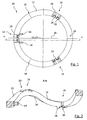
- FIGS. 15 and 16 a further embodiment of the brush ring 70 according to the invention is shown.
- Whose frame part 72 in this case has a wave-like or alternately concave and convex curved structure with trained on the recesses and elevations tooth surfaces 76, 78 as positive locking or connecting means 74.
- the teeth of the tooth surfaces 76, 78 are aligned in the radial direction, as shown particularly clearly in the side view Fig. 16 is recognizable.
- the tooth surfaces 76, 78 further extend over the entire radial width of the ring 72.
- the ring 70 or its frame part 72 is only partially formed, in particular toothed at the apex of the wave-like contour.
- only the circumferentially alternately curved at the top and bottom of the frame member 72 formed annular portions with a toothing 76, 78 are provided.
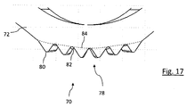
- tooth or triangular projections of the tooth surfaces 76, 78 protrude from the adjacent flat or flat outer ring structure, so that the frame member 72 in the area of the tooth-like recesses of the tooth surfaces 76, 78 nor a sufficient material thickness and strength.
- the toothing 76, 78 is also designed as a superposition to the wave-like basic geometry of the frame part 72.
- the frame part in the region of the toothings 76, 78 has an increased by the axial height of the individual teeth 80 cross-sectional area.
- the frame thus undergoes a mechanical reinforcement and stiffening, in particular in the area of the force-transmitting and torque-transmitting positive-locking means 76, 78, due to the comparatively thicker design.
- the training and the integral integration of positive locking means in the frame part thus does not lead to a weakening of the ring structure but reinforces this even.
- FIG Fig. 17 This is shown in the enlarged view in FIG Fig. 17 shown.
- the foot points or intermediate valleys 82 of the teeth 80 extending downwardly away from the imaginary outer geometry 84 in the axial direction lie in the area of the outer contour 84 of the frame part shown in dashed lines.
- the valley sections or interdental spaces 82 thus do not represent a weakening of the frame part.
- FIG. 17 a continuously curved outer contour of the frame part 72 illustrates.
- variable and universal orientation of the brush rings can provide a high or low axial bristle density.
- the embodiments shown represent only brush rings, each with three raised and recessed ring sections, the invention is by no means limited thereto. Depending on the material used and provided axial offset the ring sections can much more, about four, five or even up to ten raised and recessed ring sections are realized in the frame part. Furthermore, the invention is by no means limited to a particular trim material, such as metal wire or polypropylene bristles. It is advantageously provided that the brush ring or its frame part is formed as a press-molded part or an injection molded part and made of a thermoplastic, preferably a thermoplastic elastomer. In addition or alternatively, frame parts are also conceivable and in the context of the invention made of metal, in particular formed as a sheet metal molding.
Landscapes
- Brushes (AREA)
Priority Applications (1)
| Application Number | Priority Date | Filing Date | Title |
|---|---|---|---|
| EP11746463.6A EP2603111B1 (de) | 2010-08-09 | 2011-08-01 | Bürstenring für kehrwalzen |
Applications Claiming Priority (4)
| Application Number | Priority Date | Filing Date | Title |
|---|---|---|---|
| EP10008278A EP2417870A1 (de) | 2010-08-09 | 2010-08-09 | Bürstenring für Kehrwalzen |
| DE102011012157 | 2011-02-23 | ||
| PCT/EP2011/003841 WO2012019723A1 (de) | 2010-08-09 | 2011-08-01 | Bürstenring für kehrwalzen |
| EP11746463.6A EP2603111B1 (de) | 2010-08-09 | 2011-08-01 | Bürstenring für kehrwalzen |
Publications (2)
| Publication Number | Publication Date |
|---|---|
| EP2603111A1 EP2603111A1 (de) | 2013-06-19 |
| EP2603111B1 true EP2603111B1 (de) | 2016-03-23 |
Family
ID=45567388
Family Applications (1)
| Application Number | Title | Priority Date | Filing Date |
|---|---|---|---|
| EP11746463.6A Active EP2603111B1 (de) | 2010-08-09 | 2011-08-01 | Bürstenring für kehrwalzen |
Country Status (6)
| Country | Link |
|---|---|
| US (1) | US9289053B2 (da) |
| EP (1) | EP2603111B1 (da) |
| DK (1) | DK2603111T3 (da) |
| ES (1) | ES2576866T3 (da) |
| PL (1) | PL2603111T3 (da) |
| WO (1) | WO2012019723A1 (da) |
Families Citing this family (13)
| Publication number | Priority date | Publication date | Assignee | Title |
|---|---|---|---|---|
| USD838992S1 (en) * | 2017-11-20 | 2019-01-29 | AI Incorporated | Side brush |
| USD859843S1 (en) * | 2017-11-28 | 2019-09-17 | Al Incorporated | Side brush |
| USD849409S1 (en) * | 2017-11-28 | 2019-05-28 | AI Incorporated | Side brush |
| USD838109S1 (en) * | 2017-11-28 | 2019-01-15 | AI Incorporated | Side brush |
| USD838993S1 (en) * | 2017-11-28 | 2019-01-29 | AI Incorporated | Side brush |
| USD885062S1 (en) * | 2017-11-28 | 2020-05-26 | AI Incorporated | Side brush |
| USD849410S1 (en) * | 2017-11-28 | 2019-05-28 | AI Incorporated | Side brush |
| USD836917S1 (en) * | 2017-12-11 | 2019-01-01 | AI Incorporated | Side brush |
| USD836916S1 (en) * | 2017-12-11 | 2019-01-01 | AI Incorporated | Side brush |
| USD832585S1 (en) * | 2017-12-11 | 2018-11-06 | AI Incorporated | Side brush |
| USD836915S1 (en) * | 2017-12-11 | 2019-01-01 | AI Incorporated | Side brush |
| FI20195006A1 (fi) | 2019-01-04 | 2020-07-05 | Sajakorpi Oy | Harjakiekko |
| US20220136543A1 (en) * | 2020-11-02 | 2022-05-05 | Gallop Brush Llc | Quick-change surface panel |
Family Cites Families (8)
| Publication number | Priority date | Publication date | Assignee | Title |
|---|---|---|---|---|
| US3084367A (en) * | 1956-09-06 | 1963-04-09 | Manufacturers Brush Company | Rotary brush |
| US3274634A (en) * | 1965-07-29 | 1966-09-27 | Dendix Brushes Ltd | Rotary brushes and components for use in rotary brushes |
| DK238288A (da) | 1988-05-03 | 1989-11-04 | Maltarp As | Cirkelringformet boerstesektion til fejemaskine og fremsgangsmaade til fremstilling af en saadan boerstesektion |
| US5784748A (en) * | 1996-04-29 | 1998-07-28 | Belanger, Inc. | Vehicle laundry implement and replaceable cloth elements for use therewith |
| FI102350B (fi) | 1996-09-03 | 1998-11-30 | Sajakorpi Oy | Harjakiekko |
| SE513911C2 (sv) * | 1998-05-12 | 2000-11-27 | Leif Staahl | Borste för en roterande driven axel på en sopmaskin |
| FI20031485A0 (fi) | 2003-10-13 | 2003-10-13 | Kirkkala Oy | Harjakoneen tupsumallinen harjalamelli |
| ATE372071T1 (de) | 2004-10-08 | 2007-09-15 | Koti Onroerend Goed B V | Bürstenringanordnung |
-
2011
- 2011-08-01 PL PL11746463.6T patent/PL2603111T3/pl unknown
- 2011-08-01 WO PCT/EP2011/003841 patent/WO2012019723A1/de not_active Ceased
- 2011-08-01 EP EP11746463.6A patent/EP2603111B1/de active Active
- 2011-08-01 ES ES11746463.6T patent/ES2576866T3/es active Active
- 2011-08-01 DK DK11746463.6T patent/DK2603111T3/da active
- 2011-08-01 US US13/816,082 patent/US9289053B2/en active Active
Also Published As
| Publication number | Publication date |
|---|---|
| EP2603111A1 (de) | 2013-06-19 |
| US20130318733A1 (en) | 2013-12-05 |
| PL2603111T3 (pl) | 2016-10-31 |
| US9289053B2 (en) | 2016-03-22 |
| ES2576866T3 (es) | 2016-07-11 |
| DK2603111T3 (da) | 2016-07-04 |
| WO2012019723A1 (de) | 2012-02-16 |
Similar Documents
| Publication | Publication Date | Title |
|---|---|---|
| EP2603111B1 (de) | Bürstenring für kehrwalzen | |
| EP3600140B1 (de) | Elektrische körperpflegebürste | |
| EP1372430B1 (de) | Kopfteil für eine elektrische zahnbürste | |
| DE10144840B4 (de) | Beschlag für einen Fahrzeugsitz | |
| DE102009040504A1 (de) | Beschlag für einen Fahrzeugsitz | |
| EP3315800B1 (de) | Antriebswelle in einem handgeführten arbeitsgerät | |
| DE112011105531T5 (de) | Flexibles, außen verzahntes Zahnrad für ein Wellgetriebe | |
| EP2446175B1 (de) | Flachdichtung mit einer vollsicke | |
| DE3026685A1 (de) | Zahnrad | |
| DE69803477T2 (de) | Trommelmotor | |
| EP3969393A1 (de) | Kettenrad, trommelmotor, kettenradhalbzeug und verfahren zum herstellen eines kettenrads | |
| EP3088756B1 (de) | Klauenkupplung | |
| EP0001268B1 (de) | Elastische Kupplung | |
| DE60314056T2 (de) | Kupplungszahnrad mit Verzahnung und Verfahren zur Herstellung desselben | |
| EP3786480A1 (de) | Zahnscheibe eines zahnriementriebs mit unsymmetrischem zahnprofil | |
| EP2417870A1 (de) | Bürstenring für Kehrwalzen | |
| DE102017111039A1 (de) | Mehrteiliges Zahnrad mit Welle-Nabe-Verbindung | |
| DE102008013531A1 (de) | Kupplungsvorrichtung | |
| WO1999011436A1 (de) | Kraftübertragungsprofil, insbesondere an einem mehrkant-schraubwerkzeug | |
| WO2014206409A1 (de) | Segmentiertes trägerblech | |
| WO2006063720A1 (de) | Beschlag für einen fahrzeugsitz | |
| DE10290270B3 (de) | Anbringung einer radialen Flachscheibe an einer Nabe, insbesondere für eine Kupplungsscheibe eines Kraftfahrzeugs | |
| DE102012001283A1 (de) | Positioniervorrichtung, insbesondere für einen Gurtbringer, und Gurtschlossvorrichtung | |
| AT520531B1 (de) | Zahnrad | |
| EP1146242A1 (de) | Synchronkörper einer Synchronisiereinrichtung aus Blech |
Legal Events
| Date | Code | Title | Description |
|---|---|---|---|
| PUAI | Public reference made under article 153(3) epc to a published international application that has entered the european phase |
Free format text: ORIGINAL CODE: 0009012 |
|
| 17P | Request for examination filed |
Effective date: 20130305 |
|
| AK | Designated contracting states |
Kind code of ref document: A1 Designated state(s): AL AT BE BG CH CY CZ DE DK EE ES FI FR GB GR HR HU IE IS IT LI LT LU LV MC MK MT NL NO PL PT RO RS SE SI SK SM TR |
|
| DAX | Request for extension of the european patent (deleted) | ||
| 17Q | First examination report despatched |
Effective date: 20150608 |
|
| GRAP | Despatch of communication of intention to grant a patent |
Free format text: ORIGINAL CODE: EPIDOSNIGR1 |
|
| INTG | Intention to grant announced |
Effective date: 20151110 |
|
| GRAS | Grant fee paid |
Free format text: ORIGINAL CODE: EPIDOSNIGR3 |
|
| GRAA | (expected) grant |
Free format text: ORIGINAL CODE: 0009210 |
|
| AK | Designated contracting states |
Kind code of ref document: B1 Designated state(s): AL AT BE BG CH CY CZ DE DK EE ES FI FR GB GR HR HU IE IS IT LI LT LU LV MC MK MT NL NO PL PT RO RS SE SI SK SM TR |
|
| REG | Reference to a national code |
Ref country code: GB Ref legal event code: FG4D Free format text: NOT ENGLISH |
|
| REG | Reference to a national code |
Ref country code: CH Ref legal event code: EP |
|
| REG | Reference to a national code |
Ref country code: AT Ref legal event code: REF Ref document number: 782243 Country of ref document: AT Kind code of ref document: T Effective date: 20160415 |
|
| REG | Reference to a national code |
Ref country code: IE Ref legal event code: FG4D Free format text: LANGUAGE OF EP DOCUMENT: GERMAN |
|
| REG | Reference to a national code |
Ref country code: DE Ref legal event code: R096 Ref document number: 502011009179 Country of ref document: DE |
|
| REG | Reference to a national code |
Ref country code: CH Ref legal event code: NV Representative=s name: SIVIER, CH |
|
| REG | Reference to a national code |
Ref country code: DK Ref legal event code: T3 Effective date: 20160628 |
|
| REG | Reference to a national code |
Ref country code: ES Ref legal event code: FG2A Ref document number: 2576866 Country of ref document: ES Kind code of ref document: T3 Effective date: 20160711 |
|
| REG | Reference to a national code |
Ref country code: NL Ref legal event code: FP |
|
| REG | Reference to a national code |
Ref country code: SE Ref legal event code: TRGR |
|
| REG | Reference to a national code |
Ref country code: LT Ref legal event code: MG4D |
|
| PG25 | Lapsed in a contracting state [announced via postgrant information from national office to epo] |
Ref country code: GR Free format text: LAPSE BECAUSE OF FAILURE TO SUBMIT A TRANSLATION OF THE DESCRIPTION OR TO PAY THE FEE WITHIN THE PRESCRIBED TIME-LIMIT Effective date: 20160624 Ref country code: HR Free format text: LAPSE BECAUSE OF FAILURE TO SUBMIT A TRANSLATION OF THE DESCRIPTION OR TO PAY THE FEE WITHIN THE PRESCRIBED TIME-LIMIT Effective date: 20160323 |
|
| REG | Reference to a national code |
Ref country code: NO Ref legal event code: T2 Effective date: 20160323 |
|
| REG | Reference to a national code |
Ref country code: FR Ref legal event code: PLFP Year of fee payment: 6 |
|
| PG25 | Lapsed in a contracting state [announced via postgrant information from national office to epo] |
Ref country code: RS Free format text: LAPSE BECAUSE OF FAILURE TO SUBMIT A TRANSLATION OF THE DESCRIPTION OR TO PAY THE FEE WITHIN THE PRESCRIBED TIME-LIMIT Effective date: 20160323 Ref country code: LV Free format text: LAPSE BECAUSE OF FAILURE TO SUBMIT A TRANSLATION OF THE DESCRIPTION OR TO PAY THE FEE WITHIN THE PRESCRIBED TIME-LIMIT Effective date: 20160323 Ref country code: LT Free format text: LAPSE BECAUSE OF FAILURE TO SUBMIT A TRANSLATION OF THE DESCRIPTION OR TO PAY THE FEE WITHIN THE PRESCRIBED TIME-LIMIT Effective date: 20160323 |
|
| PG25 | Lapsed in a contracting state [announced via postgrant information from national office to epo] |
Ref country code: IS Free format text: LAPSE BECAUSE OF FAILURE TO SUBMIT A TRANSLATION OF THE DESCRIPTION OR TO PAY THE FEE WITHIN THE PRESCRIBED TIME-LIMIT Effective date: 20160723 Ref country code: EE Free format text: LAPSE BECAUSE OF FAILURE TO SUBMIT A TRANSLATION OF THE DESCRIPTION OR TO PAY THE FEE WITHIN THE PRESCRIBED TIME-LIMIT Effective date: 20160323 |
|
| PG25 | Lapsed in a contracting state [announced via postgrant information from national office to epo] |
Ref country code: RO Free format text: LAPSE BECAUSE OF FAILURE TO SUBMIT A TRANSLATION OF THE DESCRIPTION OR TO PAY THE FEE WITHIN THE PRESCRIBED TIME-LIMIT Effective date: 20160323 Ref country code: PT Free format text: LAPSE BECAUSE OF FAILURE TO SUBMIT A TRANSLATION OF THE DESCRIPTION OR TO PAY THE FEE WITHIN THE PRESCRIBED TIME-LIMIT Effective date: 20160725 Ref country code: CZ Free format text: LAPSE BECAUSE OF FAILURE TO SUBMIT A TRANSLATION OF THE DESCRIPTION OR TO PAY THE FEE WITHIN THE PRESCRIBED TIME-LIMIT Effective date: 20160323 Ref country code: SM Free format text: LAPSE BECAUSE OF FAILURE TO SUBMIT A TRANSLATION OF THE DESCRIPTION OR TO PAY THE FEE WITHIN THE PRESCRIBED TIME-LIMIT Effective date: 20160323 Ref country code: SK Free format text: LAPSE BECAUSE OF FAILURE TO SUBMIT A TRANSLATION OF THE DESCRIPTION OR TO PAY THE FEE WITHIN THE PRESCRIBED TIME-LIMIT Effective date: 20160323 |
|
| REG | Reference to a national code |
Ref country code: DE Ref legal event code: R097 Ref document number: 502011009179 Country of ref document: DE |
|
| PLBE | No opposition filed within time limit |
Free format text: ORIGINAL CODE: 0009261 |
|
| STAA | Information on the status of an ep patent application or granted ep patent |
Free format text: STATUS: NO OPPOSITION FILED WITHIN TIME LIMIT |
|
| PG25 | Lapsed in a contracting state [announced via postgrant information from national office to epo] |
Ref country code: BG Free format text: LAPSE BECAUSE OF FAILURE TO SUBMIT A TRANSLATION OF THE DESCRIPTION OR TO PAY THE FEE WITHIN THE PRESCRIBED TIME-LIMIT Effective date: 20160623 |
|
| 26N | No opposition filed |
Effective date: 20170102 |
|
| PG25 | Lapsed in a contracting state [announced via postgrant information from national office to epo] |
Ref country code: MC Free format text: LAPSE BECAUSE OF FAILURE TO SUBMIT A TRANSLATION OF THE DESCRIPTION OR TO PAY THE FEE WITHIN THE PRESCRIBED TIME-LIMIT Effective date: 20160323 |
|
| PG25 | Lapsed in a contracting state [announced via postgrant information from national office to epo] |
Ref country code: SI Free format text: LAPSE BECAUSE OF FAILURE TO SUBMIT A TRANSLATION OF THE DESCRIPTION OR TO PAY THE FEE WITHIN THE PRESCRIBED TIME-LIMIT Effective date: 20160323 |
|
| REG | Reference to a national code |
Ref country code: IE Ref legal event code: MM4A |
|
| PG25 | Lapsed in a contracting state [announced via postgrant information from national office to epo] |
Ref country code: IE Free format text: LAPSE BECAUSE OF NON-PAYMENT OF DUE FEES Effective date: 20160801 |
|
| REG | Reference to a national code |
Ref country code: FR Ref legal event code: PLFP Year of fee payment: 7 |
|
| REG | Reference to a national code |
Ref country code: CH Ref legal event code: PCAR Free format text: NEW ADDRESS: ALLEE LOUIS CRISTIN 4, 1196 GLAND (CH) |
|
| PG25 | Lapsed in a contracting state [announced via postgrant information from national office to epo] |
Ref country code: HU Free format text: LAPSE BECAUSE OF FAILURE TO SUBMIT A TRANSLATION OF THE DESCRIPTION OR TO PAY THE FEE WITHIN THE PRESCRIBED TIME-LIMIT; INVALID AB INITIO Effective date: 20110801 Ref country code: CY Free format text: LAPSE BECAUSE OF FAILURE TO SUBMIT A TRANSLATION OF THE DESCRIPTION OR TO PAY THE FEE WITHIN THE PRESCRIBED TIME-LIMIT Effective date: 20160323 |
|
| PG25 | Lapsed in a contracting state [announced via postgrant information from national office to epo] |
Ref country code: MK Free format text: LAPSE BECAUSE OF FAILURE TO SUBMIT A TRANSLATION OF THE DESCRIPTION OR TO PAY THE FEE WITHIN THE PRESCRIBED TIME-LIMIT Effective date: 20160323 Ref country code: TR Free format text: LAPSE BECAUSE OF FAILURE TO SUBMIT A TRANSLATION OF THE DESCRIPTION OR TO PAY THE FEE WITHIN THE PRESCRIBED TIME-LIMIT Effective date: 20160323 Ref country code: MT Free format text: LAPSE BECAUSE OF FAILURE TO SUBMIT A TRANSLATION OF THE DESCRIPTION OR TO PAY THE FEE WITHIN THE PRESCRIBED TIME-LIMIT Effective date: 20160323 |
|
| REG | Reference to a national code |
Ref country code: FR Ref legal event code: PLFP Year of fee payment: 8 |
|
| PG25 | Lapsed in a contracting state [announced via postgrant information from national office to epo] |
Ref country code: AL Free format text: LAPSE BECAUSE OF FAILURE TO SUBMIT A TRANSLATION OF THE DESCRIPTION OR TO PAY THE FEE WITHIN THE PRESCRIBED TIME-LIMIT Effective date: 20160323 |
|
| PGFP | Annual fee paid to national office [announced via postgrant information from national office to epo] |
Ref country code: LU Payment date: 20250822 Year of fee payment: 15 Ref country code: NL Payment date: 20250821 Year of fee payment: 15 |
|
| PGFP | Annual fee paid to national office [announced via postgrant information from national office to epo] |
Ref country code: ES Payment date: 20250925 Year of fee payment: 15 Ref country code: FI Payment date: 20250822 Year of fee payment: 15 |
|
| PGFP | Annual fee paid to national office [announced via postgrant information from national office to epo] |
Ref country code: DK Payment date: 20250825 Year of fee payment: 15 Ref country code: DE Payment date: 20250827 Year of fee payment: 15 |
|
| PGFP | Annual fee paid to national office [announced via postgrant information from national office to epo] |
Ref country code: NO Payment date: 20250826 Year of fee payment: 15 |
|
| PGFP | Annual fee paid to national office [announced via postgrant information from national office to epo] |
Ref country code: PL Payment date: 20250725 Year of fee payment: 15 Ref country code: IT Payment date: 20250825 Year of fee payment: 15 |
|
| PGFP | Annual fee paid to national office [announced via postgrant information from national office to epo] |
Ref country code: BE Payment date: 20250820 Year of fee payment: 15 Ref country code: GB Payment date: 20250820 Year of fee payment: 15 |
|
| PGFP | Annual fee paid to national office [announced via postgrant information from national office to epo] |
Ref country code: FR Payment date: 20250829 Year of fee payment: 15 Ref country code: AT Payment date: 20250821 Year of fee payment: 15 |
|
| PGFP | Annual fee paid to national office [announced via postgrant information from national office to epo] |
Ref country code: CH Payment date: 20250901 Year of fee payment: 15 Ref country code: SE Payment date: 20250820 Year of fee payment: 15 |