EP2603673B1 - Rankine-zyklus-kondensatordrucksteuerung über ein bypassventil einer energieumwandlungsvorrichtung - Google Patents
Rankine-zyklus-kondensatordrucksteuerung über ein bypassventil einer energieumwandlungsvorrichtung Download PDFInfo
- Publication number
- EP2603673B1 EP2603673B1 EP11817165.1A EP11817165A EP2603673B1 EP 2603673 B1 EP2603673 B1 EP 2603673B1 EP 11817165 A EP11817165 A EP 11817165A EP 2603673 B1 EP2603673 B1 EP 2603673B1
- Authority
- EP
- European Patent Office
- Prior art keywords
- working fluid
- condenser
- conversion device
- pressure
- energy conversion
- Prior art date
- Legal status (The legal status is an assumption and is not a legal conclusion. Google has not performed a legal analysis and makes no representation as to the accuracy of the status listed.)
- Active
Links
- 238000006243 chemical reaction Methods 0.000 title claims description 35
- 239000012530 fluid Substances 0.000 claims description 85
- 238000000034 method Methods 0.000 claims description 21
- 239000002918 waste heat Substances 0.000 claims description 10
- 238000002485 combustion reaction Methods 0.000 claims description 9
- 230000001052 transient effect Effects 0.000 claims description 9
- 230000001105 regulatory effect Effects 0.000 claims description 5
- 238000012546 transfer Methods 0.000 claims description 5
- 238000011084 recovery Methods 0.000 claims description 4
- 230000001276 controlling effect Effects 0.000 claims description 2
- 238000011144 upstream manufacturing Methods 0.000 claims description 2
- 239000002826 coolant Substances 0.000 description 9
- 239000007789 gas Substances 0.000 description 8
- 239000007788 liquid Substances 0.000 description 7
- 238000001816 cooling Methods 0.000 description 5
- 238000010586 diagram Methods 0.000 description 5
- 238000004891 communication Methods 0.000 description 4
- CRSOQBOWXPBRES-UHFFFAOYSA-N neopentane Chemical compound CC(C)(C)C CRSOQBOWXPBRES-UHFFFAOYSA-N 0.000 description 4
- OKKJLVBELUTLKV-UHFFFAOYSA-N Methanol Chemical compound OC OKKJLVBELUTLKV-UHFFFAOYSA-N 0.000 description 3
- YXFVVABEGXRONW-UHFFFAOYSA-N Toluene Chemical compound CC1=CC=CC=C1 YXFVVABEGXRONW-UHFFFAOYSA-N 0.000 description 3
- 238000005086 pumping Methods 0.000 description 3
- LYCAIKOWRPUZTN-UHFFFAOYSA-N Ethylene glycol Chemical compound OCCO LYCAIKOWRPUZTN-UHFFFAOYSA-N 0.000 description 2
- SNRUBQQJIBEYMU-UHFFFAOYSA-N dodecane Chemical compound CCCCCCCCCCCC SNRUBQQJIBEYMU-UHFFFAOYSA-N 0.000 description 2
- 239000000446 fuel Substances 0.000 description 2
- 230000006870 function Effects 0.000 description 2
- 239000000203 mixture Substances 0.000 description 2
- 238000012544 monitoring process Methods 0.000 description 2
- 239000010705 motor oil Substances 0.000 description 2
- XLYOFNOQVPJJNP-UHFFFAOYSA-N water Substances O XLYOFNOQVPJJNP-UHFFFAOYSA-N 0.000 description 2
- MHCVCKDNQYMGEX-UHFFFAOYSA-N 1,1'-biphenyl;phenoxybenzene Chemical compound C1=CC=CC=C1C1=CC=CC=C1.C=1C=CC=CC=1OC1=CC=CC=C1 MHCVCKDNQYMGEX-UHFFFAOYSA-N 0.000 description 1
- GTJOHISYCKPIMT-UHFFFAOYSA-N 2-methylundecane Chemical compound CCCCCCCCCC(C)C GTJOHISYCKPIMT-UHFFFAOYSA-N 0.000 description 1
- QULNVKABFWNUCW-UHFFFAOYSA-N 5-methylundecane Chemical compound CCCCCCC(C)CCCC QULNVKABFWNUCW-UHFFFAOYSA-N 0.000 description 1
- SGVYKUFIHHTIFL-UHFFFAOYSA-N Isobutylhexyl Natural products CCCCCCCC(C)C SGVYKUFIHHTIFL-UHFFFAOYSA-N 0.000 description 1
- 230000009286 beneficial effect Effects 0.000 description 1
- 238000009835 boiling Methods 0.000 description 1
- 238000010438 heat treatment Methods 0.000 description 1
- WGCNASOHLSPBMP-UHFFFAOYSA-N hydroxyacetaldehyde Natural products OCC=O WGCNASOHLSPBMP-UHFFFAOYSA-N 0.000 description 1
- VKPSKYDESGTTFR-UHFFFAOYSA-N isododecane Natural products CC(C)(C)CC(C)CC(C)(C)C VKPSKYDESGTTFR-UHFFFAOYSA-N 0.000 description 1
- 238000012986 modification Methods 0.000 description 1
- 230000004048 modification Effects 0.000 description 1
- TVMXDCGIABBOFY-UHFFFAOYSA-N octane Chemical compound CCCCCCCC TVMXDCGIABBOFY-UHFFFAOYSA-N 0.000 description 1
- 230000003071 parasitic effect Effects 0.000 description 1
- MSSNHSVIGIHOJA-UHFFFAOYSA-N pentafluoropropane Chemical compound FC(F)CC(F)(F)F MSSNHSVIGIHOJA-UHFFFAOYSA-N 0.000 description 1
- 238000012545 processing Methods 0.000 description 1
- NMZZYGAYPQWLGY-UHFFFAOYSA-N pyridin-3-ylmethanol;hydrofluoride Chemical compound F.OCC1=CC=CN=C1 NMZZYGAYPQWLGY-UHFFFAOYSA-N 0.000 description 1
- 239000003507 refrigerant Substances 0.000 description 1
- 229920006395 saturated elastomer Polymers 0.000 description 1
Images


Classifications
-
- F—MECHANICAL ENGINEERING; LIGHTING; HEATING; WEAPONS; BLASTING
- F01—MACHINES OR ENGINES IN GENERAL; ENGINE PLANTS IN GENERAL; STEAM ENGINES
- F01K—STEAM ENGINE PLANTS; STEAM ACCUMULATORS; ENGINE PLANTS NOT OTHERWISE PROVIDED FOR; ENGINES USING SPECIAL WORKING FLUIDS OR CYCLES
- F01K23/00—Plants characterised by more than one engine delivering power external to the plant, the engines being driven by different fluids
- F01K23/02—Plants characterised by more than one engine delivering power external to the plant, the engines being driven by different fluids the engine cycles being thermally coupled
- F01K23/06—Plants characterised by more than one engine delivering power external to the plant, the engines being driven by different fluids the engine cycles being thermally coupled combustion heat from one cycle heating the fluid in another cycle
- F01K23/065—Plants characterised by more than one engine delivering power external to the plant, the engines being driven by different fluids the engine cycles being thermally coupled combustion heat from one cycle heating the fluid in another cycle the combustion taking place in an internal combustion piston engine, e.g. a diesel engine
-
- F—MECHANICAL ENGINEERING; LIGHTING; HEATING; WEAPONS; BLASTING
- F01—MACHINES OR ENGINES IN GENERAL; ENGINE PLANTS IN GENERAL; STEAM ENGINES
- F01K—STEAM ENGINE PLANTS; STEAM ACCUMULATORS; ENGINE PLANTS NOT OTHERWISE PROVIDED FOR; ENGINES USING SPECIAL WORKING FLUIDS OR CYCLES
- F01K13/00—General layout or general methods of operation of complete plants
- F01K13/02—Controlling, e.g. stopping or starting
Definitions
- the inventions relate to a waste heat recovery system and method, and more particularly, to a system and method in which a parameter of a Rankine cycle is regulated.
- a Rankine cycle can capture a portion of heat energy that normally would be wasted (“waste heat") and convert a portion of that captured heat energy into energy that can perform useful work or into some other form of energy.
- Systems utilizing an RC are sometimes called waste heat recovery (WHR) systems.
- WHR waste heat recovery
- Such a system is for example disclosed in document US2009/0241543 .
- heat from an internal combustion engine system such as exhaust gas heat energy and other engine heat sources (e.g., engine oil, exhaust gas, charge gas, water jackets) can be captured and converted to useful energy (e.g., electrical or mechanical energy).
- useful energy e.g., electrical or mechanical energy
- FIG. 1 shows an exemplary RC system 1 including a feed pump 10, a recuperator 12, a boiler/superheater (heat exchanger) 14, an energy conversion device 16 (e.g., expander, turbine etc.), a condenser 18, and a receiver 20.
- the path of the RC through and between these elements contains a working fluid that the feed pump 10 moves along the path and provides as a high pressure liquid to the recuperator 12 and heat exchanger 14.
- the recuperator 12 is a heat exchanger that increases the thermal efficiency of the RC by transferring heat to the working fluid along a first path, and at a different point of the RC along a second path, transfers heat from the working fluid.
- the RC system 1 can include turbine as the energy conversion device 16 that rotates as a result of the expanding working fluid vapor.
- the turbine can, in turn, cause rotation of an electric generator (not shown).
- the electric power generated by the generator can be fed into a driveline motor generator (DMG) via power electronics (not shown).
- DMG driveline motor generator
- a turbine can be configured to alternatively or additionally drive some mechanical element to produce mechanical power.
- the additional converted energy can be transferred to the engine crankshaft mechanically or electrically, or used to power parasitics and/or storage batteries.
- the energy conversion device can be adapted to transfer energy from the RC system 1 to another system (e.g., to transfer heat energy from the RC system 1 to a fluid for a heating system).
- the gases exit the outlet of the energy conversion device, for example, expanded gases exiting the outlet of the turbine 16, and are then cooled and condensed via a condenser 18, which is cooled by a low temperature source (LTS) cooling medium, for example, a liquid cooling loop (circuit) including a condenser cooler having RAM airflow and condenser cooler pump (not shown) to move the cooling medium (e.g., glycol, water etc.) in the cooling loop, although other condenser cooling schemes can be employed such as a direct air-cooled heat exchanger.
- LTS low temperature source
- the expanded working fluid vapors and liquid exiting the outlet of the turbine 16 is provided along the second path through the recuperator 12, where heat is transferred from the working fluid to be stored in the recuperator 12 before entering the condenser 18.
- the condenser 18 contains one or more passageways though which the working fluid vapors and liquid moves that are cooled by a cooling medium, such as a coolant or air, to cool and condense the working fluid vapors and liquid.
- the condensed working fluid is provided as a liquid to a receiver vessel 20 where it accumulates before moving to the feed pump 10 to complete the cycle.
- the RC working fluid can be a non-organic or an organic working fluid.
- working fluid are Genetron TM R-245fa from Honeywell, Therminol TM, Dowtherm J from the Dow Chemical Co., Fluorinol, Toluene, dodecane, isododecane, methylundecane, neopentane, neopentane, octane, water/methanol mixtures, or steam.
- US 2009/0241561 A1 describes a system for converting heat from an engine into work, including a turbine that transforms the heat into work, a condenser that transforms the working fluid into liquid, a recuperator that routes working fluid from the turbine to the condenser, and a recuperator bypass.
- JP S 60222511 A describes a cycle to convert energy of a heat source, wherein a bypass valve is used to bypass a turbine.
- the invention provides a waste heat recovery (WHR) system and method in which pressure in a Rankine cycle (RC) system of the WHR system is regulated by diverting working fluid from entering an inlet of an energy conversion device of the RC system.
- WHR waste heat recovery
- RC Rankine cycle
- a system for recovering waste heat from an internal combustion engine using a Rankine cycle (RC) system includes a heat exchanger thermally coupled to a heat source associated with the internal combustion engine and adapted to transfer heat from the heat source to working fluid of the RC system, an energy conversion device fluidly coupled to the heat exchanger and adapted to receive the working fluid having the transferred heat and convert the energy of the transferred heat, a condenser fluidly coupled to the energy conversion device and adapted to receive the working fluid from which the energy was converted, and a pump positioned in a flow path of the working fluid between the condenser and the heat exchanger and adapted to move the working fluid through the RC system.
- a heat exchanger thermally coupled to a heat source associated with the internal combustion engine and adapted to transfer heat from the heat source to working fluid of the RC system
- an energy conversion device fluidly coupled to the heat exchanger and adapted to receive the working fluid having the transferred heat and convert the energy of the transferred heat
- a condenser fluidly coupled to the energy conversion device and
- the RC system includes a bypass valve having an inlet fluidly connected between an outlet of the heat exchanger and an inlet of the energy conversion device, and an outlet fluidly connected to an inlet of the condenser.
- At least one sensor is positioned in the flow path of the working fluid between the condenser and the pump and adapted to sense pressure and temperature characteristics of the working fluid and generate a signal indicative of the temperature and pressure of the working fluid.
- the RC system includes a controller adapted to regulate the condenser pressure in the RC system via controlling the bypass valve based on the generated signal.
- a method for regulating pressure of a working fluid in a Rankine cycle (RC) system that includes a working fluid path through a heat exchanger thermally coupled to a heat source of an internal combustion engine, through an energy conversion device in the working fluid path downstream of the heat exchanger, through a condenser in the working fluid path downstream of the energy conversion device, and through a pump in the working fluid path between the condenser and the heat exchanger.
- RC Rankine cycle
- the method includes sensing the temperature and pressure of the working fluid in the working fluid path between the condenser and the pump, and if the sensed pressure of the working fluid is less than a saturation pressure of the working fluid at the monitored temperature, increasing the pressure of the working fluid in the condenser by diverting at least some of the working fluid in the working fluid path upstream of an inlet of the energy conversion device to an inlet of the condenser to bypass the energy conversion device.
- the inventors have recognized that cavitation of the feed pump 10 must be overcome for efficient operation of the Rankine cycle, especially an ORC. Cavitation can result from rapid condenser pressure changes due to large engine transients or changes in condenser coolant temperature (or air temperature). The fluid in the receiver 20 can boil if the condenser pressure drops rapidly causing the feed pump 10 to cavitate when the working fluid is at saturated conditions.
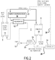
- FIG. 2 is a diagram of an exemplary RC system 2 that includes modifications of the RC 1 shown in FIG. 1 . Elements having the same reference number as shown in FIG. 1 are described above.
- the RC system 2 includes a bypass valve 22 that can route, or divert at least some of the RC working fluid at high pressure around energy conversion device 16, and also around recuperator 12 to place additional heat load on the condenser 18 when needed during transients. Both the energy conversion device 16 and recuperator 12 remove energy from the refrigerant vapor (i.e., the RC working fluid vapor).
- the working fluid By bypassing the energy conversion device 16 and recuperator 12, the working fluid will enter the condenser 18 at a higher temperature, and therefore a higher energy state compared with an RC system 1 in which all vaporized working fluid flows through the turbine and recuperator prior to the condenser 18.
- the condenser pressure is a function of the heat rejection required from it, namely, higher heat rejection requirements cause the pressure (and therefore temperature) to increase.
- the higher condenser temperature results in a greater temperature difference to the cooling medium (e.g., air or coolant). Since the receiver 20 is fluidly connected to the condenser 18 at approximately the same pressure as the condenser 18, the cavitation margin for the fluid in the receiver 20 is increased as pressure is increased.
- Opening the turbine/recuperator bypass valve 22 also reduces the high-side pressure which reduces the pumping requirement of the feed pump 10 by reducing a required pressure rise.
- the RC system 2 includes a control module 24 adapted to control the energy conversion device/recuperator bypass valve 22 in either a proportional or binary manner to regulate the condenser pressure in the Rankine cycle.
- Sensor module 26 which is adapted to sense a pressure characteristic and a temperature characteristic of the working fluid, is provided in the path of the working fluid between the condenser and the feed pump 10 and generates a signal that is provided on communication path 28 (e.g., one or more wired or wireless communication channels).
- communication path 28 e.g., one or more wired or wireless communication channels.
- the control module 24 receives a pressure signal P and a temperature signal T from sensor module 26 and continuously or periodically monitors the pressure P and temperature T of the working fluid. From the monitored values of P and T, the controller determines whether a low pressure state exists (e.g., during a transient condition) and whether the bypass valve 22 should be opened.
- a low pressure state is a state in which the working fluid is at or near a boiling point, i.e., the P when at or near the saturation pressure, PWF, saturation for a sensed T, and if the controller determines this state exists, it provides a signal on communication path 29 causing the bypass valve 22 to open.
- FIG. 3 is a process flow diagram of an exemplary method 30 that can be performed by controller 24 in an RC system 2 to determine when to open or close the bypass valve 22.
- the controller 24 monitors temperature T and pressure P characteristics of the working fluid (WF) sensed downstream of the condenser 18.
- WF working fluid
- decision 34 the controller 24 determines whether the sensed pressure P of the WF is greater than a saturation pressure of corresponding to the sensed T), i.e., if P > P WF, saturation .
- the "NO" path is take from decision 34 to process 36 in which the bypass valve 22 across a recuperator 12 and/or an energy conversion device (e.g., a turbine) 16 of the RC system is opened to increase WF pressure in a condenser 18 of the RC system 2.
- method 30 returns to the process 32 to continue monitoring the temperature and pressure of the WF. If the controller 24 determines that the sensed P corresponds to a pressure value greater than P WF, saturation , the "YES" path is take from decision 34 to process decision 38, which determines the present state of the bypass valve 22.
- the controller 24 determines that the present state of bypass valve 22 is open, the "YES" path is taken to process 40, which closes the bypass valve 22. If the present state determined by controller 24 in decision 38 indicates that the bypass valve 22 is closed, the "NO" path is taken from decision 38, and the bypass valve 22 remains closed. After either case (i.e., leaving the valve 22 closed or closing it), the method returns to process 32 and the controller 24 continues to monitor the pressure P and temperature T of the WF. It is to be appreciated that other embodiments can include more granular control of the extent that the bypass valve 22 is opened, for example, based on a load prediction algorithm, operating mode, sensed transient condition, and so on.
- Control of the bypass valve 22 can be accomplished using an actuator controlled by a controller, for example, controller 24 or another controller communicating with controller 24, to open the valve 22 based on the generated signal.
- the controller can, via communication path 29, instruct valve 22 to open entirely, or as pointed out above, to an extent based on the magnitude of the transient condition.
- the controller 24 can determine, for example, from a lookup table, map or mathematical relation, what minimum pressure for a monitored temperature must be maintained and then control the pressure of the working fluid in the condenser via operation of the bypass valve 22 to prevent cavitation in the feed pump 10.
- the control module 24 can be, for example, an electronic control unit (ECU) or electronic control module (ECM) that monitors the performance of the engine (not shown) and other elements of a vehicle.
- the control module 24 can be a single unit or plural control units that collectively perform these monitoring and control functions of the engine and condenser coolant system.
- the control module 24 can be provided separate from the coolant systems and communicate electrically with systems via one or more data and/or power paths.
- the control module 24 can also utilize sensors, such as pressure, temperature sensors in addition to the sensors 26 to monitor the system components and determine whether the these systems are functioning properly.
- the control module 24 can generate control signals based on information provided by sensors described herein and perhaps other information, for example, stored in a database or memory integral with or separate from the control module 24.
- the control module 24 can include a processor and modules in the form of software or routines that are stored on computer readable media such as memory (e.g., read-only memory, flash memory etc.), which is executable by the processor of the control module. For example, instructions for carrying out the processes shown in FIG. 3 can be stored with the control module 24 or stored elsewhere, but accessible by the control module 24.
- modules of control module 24 can include electronic circuits (i.e., hardware) for performing some or all or part of the processing, including analog and/or digital circuitry. These modules can comprise a combination of software, electronic circuits and microprocessor based components.
- the control module 24 can be an application specific module or it can receive data indicative of engine performance and exhaust gas composition including, but not limited to any of engine position sensor data, speed sensor data, exhaust mass flow sensor data, fuel rate data, pressure sensor data, temperature sensor data from locations throughout the engine and an exhaust aftertreatment system, data regarding requested power, and other data.
- the control module can then generate control signals and output these signals to control elements of the RC, the engine, the aftertreatment system, and/or other systems and devices associated with a vehicle.
- a bypass valve can be controlled to bypass (or divert) hot vapor around a recuperator and/or an energy conversion device of an RC system to increase the internal energy of the fluid entering the RC system condenser, and therefore increase the pressure of the working fluid in the condenser (and receiver pressure).
- the increased condenser and receiver pressure is beneficial during extreme transient operation of the system because it reduces the likelihood of the feed pump losing its prime by increasing the fluid's cavitation margin. This facilitates working fluid pumping without cavitation, which facilitates achieving emission-critical cooling of EGR gases and a decrease of wear on the feed pump.
- recuperator heat exchanger
- other embodiments consistent with the disclosure can be configured across the energy conversion device without a recuperator.
- an embodiment of an RC system can be configured without a receiver between the condenser and the feed pump.
- the bypass valve can be used as a load limiting device for an expander (e.g., a turbine).
- Embodiments of the disclosed RC system condenser pressure regulation using a bypass valve to bypass the recuperator and/or energy conversion device can be applied to any type of internal combustion engine (e.g., diesel or gasoline engines) and can provide a large improvement in fuel economy and aid in the operation of RC system during transient engine cycles (e.g., in mobile on-highway vehicle applications) and/or rapidly changing temperatures.
- any type of internal combustion engine e.g., diesel or gasoline engines
- transient engine cycles e.g., in mobile on-highway vehicle applications
Landscapes
- Engineering & Computer Science (AREA)
- Chemical & Material Sciences (AREA)
- Combustion & Propulsion (AREA)
- Mechanical Engineering (AREA)
- General Engineering & Computer Science (AREA)
- Engine Equipment That Uses Special Cycles (AREA)
- Control Of Turbines (AREA)
Claims (6)
- System zur Nutzung von Abwärme von einem Verbrennungsmotor unter Verwendung eines Rankine-Kreislauf- (RC) Systems (1), umfassend:einen Wärmetauscher (14), der thermisch mit einer Wärmequelle gekoppelt ist, die mit dem Verbrennungsmotor assoziiert und eingerichtet ist zum Übertragen von Wärme von der Wärmequelle zu Arbeitsfluid des RC-Systems (1);eine Energieumwandlungsvorrichtung (16), die fluidisch gekoppelt ist mit dem Wärmetauscher (14) und eingerichtet ist zum Empfangen des Arbeitsfluids, dem Wärme übertagen wurde, und Umwandeln der Energie der übertragenen Wärme;einen Kondensor (18), der fluidisch gekoppelt ist mit der Energieumwandlungsvorrichtung (16) und eingerichtet ist zum Empfanges des Arbeitsfluids, von dem die Energie umgewandelt wurde;eine Pumpe (10), die in einem Strömungspfad des Arbeitsfluids zwischen dem Kondensor (18) und dem Wärmetauscher (14) positioniert ist, wobei die besagte Pumpe (10) eingerichtet ist zum Befördern des Arbeitsfluids durch das RC-System (1);ein Umgehungsventil (22), das einen Einlass hat, welcher fluidisch zwischen einem Auslass des Wärmetauschers (14) und einem Einlass der Energieumwandlungsvorrichtung (16) verbunden ist, und das einen Auslass hat, welcher mit einem Einlass des Kondensors (18) fluidisch verbunden ist;mindestens ein Sensor (26) in dem Strömungspfad des Arbeitsfluids zwischen dem Kondensor (18) und der Pumpe (10), welcher eingerichtet ist zum Messen von Druck- und Temperaturcharakteristiken des Arbeitsfluids und zum Erzeugen eines Signals, das die Temperatur und den Druck des Arbeitsfluids angibt, wobei der mindestens eine Sensor (26) eingerichtet ist zum Messen einer transienten Bedingung; undein Steuergerät (24), das eingerichtet ist zum Regulieren des Drucks des Kondensors (18) in dem RC-System (1) über Steuern des Umgehungsventils (22) basierend auf dem erzeugten Signal und das eingerichtet ist zum Steuern eines Ausmaßes, zu welchem das Umgehungsventil (22) geöffnet wird, basierend auf einer Größe der gemessenen transienten Bedingung.
- Das System nach Anspruch 1, wobei das Steuergerät (24) eingerichtet ist zum Bestimmen, ob der Druck des Arbeitsfluids in dem Strömungspfad größer ist als ein Sättigungsdruck des Arbeitsfluids für die gemessene Temperatur.
- Das System nach Anspruch 1, wobei das RC-System (1) einen Rekuperator (12) enthält, der einen Einlass hat, welcher mit dem Auslass der Energieumwandlungsvorrichtung (16) fluidisch gekoppelt ist, und der einen Auslass hat, welcher mit dem besagten Auslass des besagten Umgehungsventils (22) fluidisch gekoppelt ist.
- Das Abwärmenutzungssystem nach Anspruch 1, wobei die besagte Energieumwandlungsvorrichtung eine Turbine ist, und das besagte RC-System (1) außerdem einen Rekuperator (12) umfasst, der einen ersten Pfad hat, welcher zwischen einem Auslass der Pumpe (10) und einem Einlass des Wärmetauschers (14) fluidisch verbunden ist, und einen zweiten Pfad, der zwischen einem Auslass der Energieumwandlungsvorrichtung (16) und dem Einlass des Kondensors (18) fluidisch gekoppelt ist, wobei der Auslass des Umgehungsventils (22) zwischen dem Einlass des Kondensors (18) und einem Auslass des zweiten Pfads des Rekuperators (12) verbunden ist.
- Verfahren zum Regulieren von Druck eines Arbeitsfluids in einem Rankinekreislauf- (RC) Systems (1), umfassend einen Arbeitsfluidpfad durch einen Wärmetauscher (14), der thermisch gekoppelt ist mit einer Wärmequelle eines Verbrennungsmotors, durch eine Energieumwandlungsvorrichtung (16) in dem Arbeitsfluidpfad stromabwärts von dem Wärmetauscher (14), durch einen Kondensor (18) in dem Arbeitsfluidpfad stromabwärts von der Energieumwandlungsvorrichtung (16), und durch eine Pumpe (10) in dem Arbeitsfluidpfad zwischen dem Kondensor (18) und dem Wärmetauscher (14), wobei das Verfahren umfasst:Messen einer transienten Bedingung, der Temperatur und des Drucks des Arbeitsfluids in dem Arbeitsfluidpfad zwischen dem Kondensor (18) und der Pumpe (10);wenn der gemessene Druck des Arbeitsfluids kleiner ist als ein Sättigungsdruck des Arbeitsfluids bei der gemessenen Temperatur: Erhöhen des Drucks des Arbeitsfluids in dem Kondensor (18) durch Umlenken von mindestens einem Teil des Arbeitsfluids in dem Arbeitsfluidpfad stromaufwärts von einem Einlass der Energieumwandlungsvorrichtung (16) zu einem Einlass des Kondensors (18), um die Energieumwandlungsvorrichtung (16) zu umgehen, wobei ein Ausmaß, zu welchem ein Umgehungsventil (22) geöffnet wird, basierend auf einer Größe der gemessenen transienten Bedingung gesteuert wird.
- Das Verfahren nach Anspruch 5, wobei das RC-System (1) außerdem einen Rekuperator (12) enthält, der einen Einlass hat, welcher mit dem Auslass der Energieumwandlungsvorrichtung (16) fluidisch gekoppelt ist, und der einen Auslass hat, welcher mit einem Einlass des Kondensors (18) fluidisch gekoppelt ist, und das besagte umgelenkte Arbeitsfluid den besagten Rekuperator (12) umgeht.
Applications Claiming Priority (2)
| Application Number | Priority Date | Filing Date | Title |
|---|---|---|---|
| US37365710P | 2010-08-13 | 2010-08-13 | |
| PCT/US2011/047700 WO2012021881A2 (en) | 2010-08-13 | 2011-08-13 | Rankine cycle condenser pressure control using an energy conversion device bypass valve |
Publications (3)
| Publication Number | Publication Date |
|---|---|
| EP2603673A2 EP2603673A2 (de) | 2013-06-19 |
| EP2603673A4 EP2603673A4 (de) | 2014-07-02 |
| EP2603673B1 true EP2603673B1 (de) | 2019-12-25 |
Family
ID=45568238
Family Applications (1)
| Application Number | Title | Priority Date | Filing Date |
|---|---|---|---|
| EP11817165.1A Active EP2603673B1 (de) | 2010-08-13 | 2011-08-13 | Rankine-zyklus-kondensatordrucksteuerung über ein bypassventil einer energieumwandlungsvorrichtung |
Country Status (4)
| Country | Link |
|---|---|
| US (1) | US8683801B2 (de) |
| EP (1) | EP2603673B1 (de) |
| CN (1) | CN103180554B (de) |
| WO (1) | WO2012021881A2 (de) |
Families Citing this family (49)
| Publication number | Priority date | Publication date | Assignee | Title |
|---|---|---|---|---|
| DE112011104516B4 (de) * | 2010-12-23 | 2017-01-19 | Cummins Intellectual Property, Inc. | System und Verfahren zur Regulierung einer EGR-Kühlung unter Verwendung eines Rankine-Kreisprozesses |
| DE102012000100A1 (de) * | 2011-01-06 | 2012-07-12 | Cummins Intellectual Property, Inc. | Rankine-kreisprozess-abwärmenutzungssystem |
| JP5597597B2 (ja) * | 2011-06-09 | 2014-10-01 | 株式会社神戸製鋼所 | 発電装置 |
| WO2013028166A2 (en) * | 2011-08-22 | 2013-02-28 | International Engine Intellectual Property Company, Llc | Waste heat recovery system for controlling egr outlet temperature |
| WO2013028173A1 (en) * | 2011-08-23 | 2013-02-28 | International Engine Intellectual Property Company, Llc | System and method for protecting an engine from condensation at intake |
| WO2013165431A1 (en) * | 2012-05-03 | 2013-11-07 | International Engine Intellectual Property Company, Llc | Rankine cycle mid-temperature recuperation |
| US9118226B2 (en) * | 2012-10-12 | 2015-08-25 | Echogen Power Systems, Llc | Heat engine system with a supercritical working fluid and processes thereof |
| JP6360835B2 (ja) * | 2012-10-17 | 2018-07-18 | ノアグレン リミテッド | 乗物の廃熱回収システム |
| US9140209B2 (en) * | 2012-11-16 | 2015-09-22 | Cummins Inc. | Rankine cycle waste heat recovery system |
| JP6179736B2 (ja) * | 2013-01-16 | 2017-08-16 | パナソニックIpマネジメント株式会社 | ランキンサイクル装置 |
| NO335230B1 (no) * | 2013-02-19 | 2014-10-27 | Viking Heat Engines As | Anordning og framgangsmåte for drifts- og sikkerhetsregulering ved en varmekraftmaskin |
| EP2964911B1 (de) | 2013-03-04 | 2022-02-23 | Echogen Power Systems LLC | Wärmekraftmaschinensysteme mit überkritischen kohlendioxidkreisläufen mit hoher nettoleistung |
| WO2014164826A1 (en) * | 2013-03-12 | 2014-10-09 | Echogen Power Systems, L.L.C. | Management of working fluid during heat engine system shutdown |
| DE102013213581A1 (de) | 2013-07-11 | 2015-01-15 | Mahle International Gmbh | Wärmerückgewinnungssystem für einen Verbrennungsmotor |
| EP2865854B1 (de) * | 2013-10-23 | 2021-08-18 | Orcan Energy AG | Vorrichtung und Verfahren zum zuverlässigen Starten von ORC Systemen |
| JP2015214922A (ja) * | 2014-05-09 | 2015-12-03 | 株式会社神戸製鋼所 | 熱エネルギー回収装置および熱エネルギー回収装置の起動方法 |
| US20170201158A1 (en) * | 2014-05-30 | 2017-07-13 | Leartek Pty Ltd | Exhaust heat recovery system control method and device |
| DE102014218485A1 (de) * | 2014-09-15 | 2016-03-17 | Robert Bosch Gmbh | Abwärmenutzungsanordnung einer Brennkraftmaschine und Verfahren zum Betrieb einer Abwärmenutzungsanordnung |
| US10570777B2 (en) | 2014-11-03 | 2020-02-25 | Echogen Power Systems, Llc | Active thrust management of a turbopump within a supercritical working fluid circuit in a heat engine system |
| US10161270B2 (en) * | 2015-09-03 | 2018-12-25 | Avl Powertrain Engineering, Inc. | Rankine cycle pump and recuperator design for multiple boiler systems |
| JP2017053278A (ja) * | 2015-09-10 | 2017-03-16 | アネスト岩田株式会社 | バイナリー発電装置 |
| US10294891B2 (en) | 2015-11-12 | 2019-05-21 | Innovation Management And Sustainable Technologies S.A. De C.V. | Energy collector system applicable to combustion engines |
| WO2017112583A1 (en) * | 2015-12-21 | 2017-06-29 | Cummins Inc. | Waste heat recovery power drive |
| DE112015007098T5 (de) * | 2015-12-21 | 2018-08-02 | Cummins Inc. | Integriertes steuersystem zur motorabwärmerückgewinnung mithilfe eines organic-rankine-cycle |
| ITUA20163546A1 (it) * | 2016-05-18 | 2017-11-18 | Turboden Srl | Impianto a ciclo rankine organico cogenerativo |
| US10400652B2 (en) * | 2016-06-09 | 2019-09-03 | Cummins Inc. | Waste heat recovery architecture for opposed-piston engines |
| CN110249122B (zh) | 2017-02-10 | 2022-04-15 | 康明斯公司 | 用于使废热回收系统中的流膨胀的系统和方法 |
| US11204190B2 (en) | 2017-10-03 | 2021-12-21 | Enviro Power, Inc. | Evaporator with integrated heat recovery |
| EP3692304A4 (de) | 2017-10-03 | 2021-07-07 | Enviro Power, Inc. | Verdampfer mit integrierter wärmerückgewinnung |
| US11187112B2 (en) | 2018-06-27 | 2021-11-30 | Echogen Power Systems Llc | Systems and methods for generating electricity via a pumped thermal energy storage system |
| SE542760C2 (en) * | 2018-12-14 | 2020-07-07 | Climeon Ab | Method and controller for preventing formation of droplets in a heat exchanger |
| CN110444301B (zh) * | 2019-08-13 | 2022-07-01 | 中国核动力研究设计院 | 模拟超临界压力瞬变工况实验装置与实验方法 |
| US11435120B2 (en) | 2020-05-05 | 2022-09-06 | Echogen Power Systems (Delaware), Inc. | Split expansion heat pump cycle |
| US11629638B2 (en) | 2020-12-09 | 2023-04-18 | Supercritical Storage Company, Inc. | Three reservoir electric thermal energy storage system |
| CN113146817B (zh) * | 2021-03-04 | 2022-12-13 | 贵州迪森元能源科技有限公司 | 余气利用自动控制系统 |
| US11644015B2 (en) | 2021-04-02 | 2023-05-09 | Ice Thermal Harvesting, Llc | Systems and methods for generation of electrical power at a drilling rig |
| US11493029B2 (en) | 2021-04-02 | 2022-11-08 | Ice Thermal Harvesting, Llc | Systems and methods for generation of electrical power at a drilling rig |
| US12312981B2 (en) | 2021-04-02 | 2025-05-27 | Ice Thermal Harvesting, Llc | Systems and methods utilizing gas temperature as a power source |
| US11280322B1 (en) | 2021-04-02 | 2022-03-22 | Ice Thermal Harvesting, Llc | Systems for generating geothermal power in an organic Rankine cycle operation during hydrocarbon production based on wellhead fluid temperature |
| US11293414B1 (en) | 2021-04-02 | 2022-04-05 | Ice Thermal Harvesting, Llc | Systems and methods for generation of electrical power in an organic rankine cycle operation |
| US11326550B1 (en) | 2021-04-02 | 2022-05-10 | Ice Thermal Harvesting, Llc | Systems and methods utilizing gas temperature as a power source |
| US11421663B1 (en) | 2021-04-02 | 2022-08-23 | Ice Thermal Harvesting, Llc | Systems and methods for generation of electrical power in an organic Rankine cycle operation |
| US11480074B1 (en) | 2021-04-02 | 2022-10-25 | Ice Thermal Harvesting, Llc | Systems and methods utilizing gas temperature as a power source |
| US11486370B2 (en) | 2021-04-02 | 2022-11-01 | Ice Thermal Harvesting, Llc | Modular mobile heat generation unit for generation of geothermal power in organic Rankine cycle operations |
| US11592009B2 (en) | 2021-04-02 | 2023-02-28 | Ice Thermal Harvesting, Llc | Systems and methods for generation of electrical power at a drilling rig |
| US12516855B2 (en) | 2022-10-27 | 2026-01-06 | Supercritical Storage Company, Inc. | High-temperature, dual rail heat pump cycle for high performance at high-temperature lift and range |
| US12534990B2 (en) | 2022-12-29 | 2026-01-27 | Ice Thermal Harvesting, Llc | Power generation assemblies for hydraulic fracturing systems and methods |
| US12180861B1 (en) | 2022-12-30 | 2024-12-31 | Ice Thermal Harvesting, Llc | Systems and methods to utilize heat carriers in conversion of thermal energy |
| WO2025010090A1 (en) | 2023-02-07 | 2025-01-09 | Supercritical Storage Company, Inc. | Waste heat integration into pumped thermal energy storage |
Family Cites Families (131)
| Publication number | Priority date | Publication date | Assignee | Title |
|---|---|---|---|---|
| US3232052A (en) | 1962-12-28 | 1966-02-01 | Creusot Forges Ateliers | Power producing installation comprising a steam turbine and at least one gas turbine |
| US7117827B1 (en) | 1972-07-10 | 2006-10-10 | Hinderks Mitja V | Means for treatment of the gases of combustion engines and the transmission of their power |
| US3789804A (en) | 1972-12-14 | 1974-02-05 | Sulzer Ag | Steam power plant with a flame-heated steam generator and a group of gas turbines |
| US4009587A (en) | 1975-02-18 | 1977-03-01 | Scientific-Atlanta, Inc. | Combined loop free-piston heat pump |
| US4164850A (en) | 1975-11-12 | 1979-08-21 | Lowi Jr Alvin | Combined engine cooling system and waste-heat driven automotive air conditioning system |
| US4204401A (en) | 1976-07-19 | 1980-05-27 | The Hydragon Corporation | Turbine engine with exhaust gas recirculation |
| US4271664A (en) | 1977-07-21 | 1981-06-09 | Hydragon Corporation | Turbine engine with exhaust gas recirculation |
| CH627524A5 (de) | 1978-03-01 | 1982-01-15 | Sulzer Ag | Verfahren und anlage zur waermenutzung durch waermeentzug aus mindestens einem stroemenden waermetraeger. |
| JPS5532916A (en) * | 1978-08-25 | 1980-03-07 | Hitachi Ltd | Method of making temperature of steam turbine metal of combined plant constant and its device |
| US4267692A (en) | 1979-05-07 | 1981-05-19 | Hydragon Corporation | Combined gas turbine-rankine turbine power plant |
| JPS57179509A (en) * | 1981-04-28 | 1982-11-05 | Tokyo Shibaura Electric Co | Method of controlling temperature of superheated steam of boiler |
| JPS5814404U (ja) * | 1981-07-22 | 1983-01-29 | 株式会社東芝 | ランキンサイクル装置 |
| US4428190A (en) | 1981-08-07 | 1984-01-31 | Ormat Turbines, Ltd. | Power plant utilizing multi-stage turbines |
| US4458493A (en) | 1982-06-18 | 1984-07-10 | Ormat Turbines, Ltd. | Closed Rankine-cycle power plant utilizing organic working fluid |
| US4581897A (en) | 1982-09-29 | 1986-04-15 | Sankrithi Mithra M K V | Solar power collection apparatus |
| DE3390316C2 (de) | 1982-11-18 | 1994-06-01 | Evans Cooling Ass | Verfahren und Kühlsystem zur Verdampfungskühlung von Verbrennungsmotoren |
| JPS60222511A (ja) * | 1985-03-27 | 1985-11-07 | Hitachi Ltd | 冷熱発電設備 |
| JPS6419157A (en) | 1987-07-10 | 1989-01-23 | Kubota Ltd | Waste heat recovering device for water cooled engine |
| US4831817A (en) | 1987-11-27 | 1989-05-23 | Linhardt Hans D | Combined gas-steam-turbine power plant |
| US4873829A (en) | 1988-08-29 | 1989-10-17 | Williamson Anthony R | Steam power plant |
| JP2567298B2 (ja) | 1990-11-29 | 1996-12-25 | 帝国ピストンリング株式会社 | 多気筒エンジンにおけるシリンダの冷却構造 |
| US5121607A (en) | 1991-04-09 | 1992-06-16 | George Jr Leslie C | Energy recovery system for large motor vehicles |
| US5421157A (en) | 1993-05-12 | 1995-06-06 | Rosenblatt; Joel H. | Elevated temperature recuperator |
| US6014856A (en) | 1994-09-19 | 2000-01-18 | Ormat Industries Ltd. | Multi-fuel, combined cycle power plant |
| JPH08200075A (ja) | 1995-01-30 | 1996-08-06 | Toyota Motor Corp | 内燃機関の燃焼室 |
| US5685152A (en) | 1995-04-19 | 1997-11-11 | Sterling; Jeffrey S. | Apparatus and method for converting thermal energy to mechanical energy |
| US5950425A (en) | 1996-03-11 | 1999-09-14 | Sanshin Kogyo Kabushiki Kaisha | Exhaust manifold cooling |
| JP3822279B2 (ja) | 1996-05-22 | 2006-09-13 | 臼井国際産業株式会社 | Egrガス冷却装置 |
| US5806322A (en) | 1997-04-07 | 1998-09-15 | York International | Refrigerant recovery method |
| US5771868A (en) | 1997-07-03 | 1998-06-30 | Turbodyne Systems, Inc. | Turbocharging systems for internal combustion engines |
| US6138649A (en) | 1997-09-22 | 2000-10-31 | Southwest Research Institute | Fast acting exhaust gas recirculation system |
| US6055959A (en) | 1997-10-03 | 2000-05-02 | Yamaha Hatsudoki Kabushiki Kaisha | Engine supercharged in crankcase chamber |
| US20020099476A1 (en) | 1998-04-02 | 2002-07-25 | Hamrin Douglas A. | Method and apparatus for indirect catalytic combustor preheating |
| US6230480B1 (en) | 1998-08-31 | 2001-05-15 | Rollins, Iii William Scott | High power density combined cycle power plant |
| US6035643A (en) | 1998-12-03 | 2000-03-14 | Rosenblatt; Joel H. | Ambient temperature sensitive heat engine cycle |
| US6571548B1 (en) | 1998-12-31 | 2003-06-03 | Ormat Industries Ltd. | Waste heat recovery in an organic energy converter using an intermediate liquid cycle |
| US6321697B1 (en) | 1999-06-07 | 2001-11-27 | Mitsubishi Heavy Industries, Ltd. | Cooling apparatus for vehicular engine |
| DE19939289C1 (de) | 1999-08-19 | 2000-10-05 | Mak Motoren Gmbh & Co Kg | Verfahren und Einrichtung zur Aufbereitung von Gasgemischen |
| JP3767785B2 (ja) | 1999-10-22 | 2006-04-19 | 本田技研工業株式会社 | エンジンの排熱回収装置 |
| US6393840B1 (en) | 2000-03-01 | 2002-05-28 | Ter Thermal Retrieval Systems Ltd. | Thermal energy retrieval system for internal combustion engines |
| US6247316B1 (en) | 2000-03-22 | 2001-06-19 | Clean Energy Systems, Inc. | Clean air engines for transportation and other power applications |
| GB0007917D0 (en) | 2000-03-31 | 2000-05-17 | Npower | An engine |
| US6701712B2 (en) | 2000-05-24 | 2004-03-09 | Ormat Industries Ltd. | Method of and apparatus for producing power |
| US6960839B2 (en) | 2000-07-17 | 2005-11-01 | Ormat Technologies, Inc. | Method of and apparatus for producing power from a heat source |
| JP2002115801A (ja) | 2000-10-05 | 2002-04-19 | Honda Motor Co Ltd | 蒸発器の蒸気温度制御装置 |
| JP2002115505A (ja) | 2000-10-11 | 2002-04-19 | Honda Motor Co Ltd | 内燃機関のランキンサイクル装置 |
| EP1374252B1 (de) | 2001-03-30 | 2007-05-02 | Pebble Bed Modular Reactor (Proprietary) Limited | Kernreaktoranlage und verfahren zum konditionieren deren stromerzeugungskreis |
| JP3871193B2 (ja) | 2001-07-03 | 2007-01-24 | 本田技研工業株式会社 | エンジンの排熱回収装置 |
| US20030213246A1 (en) | 2002-05-15 | 2003-11-20 | Coll John Gordon | Process and device for controlling the thermal and electrical output of integrated micro combined heat and power generation systems |
| US6598397B2 (en) | 2001-08-10 | 2003-07-29 | Energetix Micropower Limited | Integrated micro combined heat and power system |
| DE10236324A1 (de) | 2001-08-17 | 2003-03-06 | Alstom Switzerland Ltd | Verfahren zum Kühlen von Turbinenschaufeln |
| US6637207B2 (en) | 2001-08-17 | 2003-10-28 | Alstom (Switzerland) Ltd | Gas-storage power plant |
| DE10236501A1 (de) | 2001-08-17 | 2003-04-03 | Alstom Switzerland Ltd | Startverfahren für eine Kraftwerksanlage |
| DE10236294A1 (de) | 2001-08-17 | 2003-02-27 | Alstom Switzerland Ltd | Gasversorgungskontrolleinrichtung einer Gasspeicherkraftanlage |
| JP3730900B2 (ja) | 2001-11-02 | 2006-01-05 | 本田技研工業株式会社 | 内燃機関 |
| JP3881872B2 (ja) | 2001-11-15 | 2007-02-14 | 本田技研工業株式会社 | 内燃機関 |
| US6748934B2 (en) | 2001-11-15 | 2004-06-15 | Ford Global Technologies, Llc | Engine charge air conditioning system with multiple intercoolers |
| US6848259B2 (en) | 2002-03-20 | 2005-02-01 | Alstom Technology Ltd | Compressed air energy storage system having a standby warm keeping system including an electric air heater |
| WO2003095923A1 (en) | 2002-05-10 | 2003-11-20 | Usui Kokusai Sangyo Kaisha, Ltd. | Heat transfer pipe and heat exchange incorporating such heat transfer pipe |
| US20030213248A1 (en) | 2002-05-15 | 2003-11-20 | Osborne Rodney L. | Condenser staging and circuiting for a micro combined heat and power system |
| US20030213245A1 (en) | 2002-05-15 | 2003-11-20 | Yates Jan B. | Organic rankine cycle micro combined heat and power system |
| AT414156B (de) | 2002-10-11 | 2006-09-15 | Dirk Peter Dipl Ing Claassen | Verfahren und einrichtung zur rückgewinnung von energie |
| US8444874B2 (en) | 2002-10-25 | 2013-05-21 | Honeywell International Inc. | Heat transfer methods using heat transfer compositions containing trans-1,3,3,3-tetrafluoropropene |
| US6880344B2 (en) | 2002-11-13 | 2005-04-19 | Utc Power, Llc | Combined rankine and vapor compression cycles |
| US7174716B2 (en) | 2002-11-13 | 2007-02-13 | Utc Power Llc | Organic rankine cycle waste heat applications |
| US6877323B2 (en) | 2002-11-27 | 2005-04-12 | Elliott Energy Systems, Inc. | Microturbine exhaust heat augmentation system |
| US6745574B1 (en) | 2002-11-27 | 2004-06-08 | Elliott Energy Systems, Inc. | Microturbine direct fired absorption chiller |
| US6751959B1 (en) * | 2002-12-09 | 2004-06-22 | Tennessee Valley Authority | Simple and compact low-temperature power cycle |
| SE0301585D0 (sv) | 2003-05-30 | 2003-05-30 | Euroturbine Ab | Förfarande för drift av en gasturbingrupp |
| US6986251B2 (en) | 2003-06-17 | 2006-01-17 | Utc Power, Llc | Organic rankine cycle system for use with a reciprocating engine |
| US6964168B1 (en) | 2003-07-09 | 2005-11-15 | Tas Ltd. | Advanced heat recovery and energy conversion systems for power generation and pollution emissions reduction, and methods of using same |
| US7007487B2 (en) | 2003-07-31 | 2006-03-07 | Mes International, Inc. | Recuperated gas turbine engine system and method employing catalytic combustion |
| US7159400B2 (en) | 2003-10-02 | 2007-01-09 | Honda Motor Co., Ltd. | Rankine cycle apparatus |
| US7174732B2 (en) | 2003-10-02 | 2007-02-13 | Honda Motor Co., Ltd. | Cooling control device for condenser |
| US7131290B2 (en) | 2003-10-02 | 2006-11-07 | Honda Motor Co., Ltd. | Non-condensing gas discharge device of condenser |
| JP4089619B2 (ja) | 2004-01-13 | 2008-05-28 | 株式会社デンソー | ランキンサイクルシステム |
| JP4526395B2 (ja) | 2004-02-25 | 2010-08-18 | 臼井国際産業株式会社 | 内燃機関の過給システム |
| US7325401B1 (en) | 2004-04-13 | 2008-02-05 | Brayton Energy, Llc | Power conversion systems |
| US7200996B2 (en) | 2004-05-06 | 2007-04-10 | United Technologies Corporation | Startup and control methods for an ORC bottoming plant |
| JP2005329843A (ja) | 2004-05-20 | 2005-12-02 | Toyota Industries Corp | 車両用排熱回収システム |
| US7469540B1 (en) | 2004-08-31 | 2008-12-30 | Brent William Knapton | Energy recovery from waste heat sources |
| US7028463B2 (en) | 2004-09-14 | 2006-04-18 | General Motors Corporation | Engine valve assembly |
| US7665304B2 (en) | 2004-11-30 | 2010-02-23 | Carrier Corporation | Rankine cycle device having multiple turbo-generators |
| US7121906B2 (en) | 2004-11-30 | 2006-10-17 | Carrier Corporation | Method and apparatus for decreasing marine vessel power plant exhaust temperature |
| DE102005013287B3 (de) | 2005-01-27 | 2006-10-12 | Misselhorn, Jürgen, Dipl.Ing. | Wärmekraftmaschine |
| US7225621B2 (en) | 2005-03-01 | 2007-06-05 | Ormat Technologies, Inc. | Organic working fluids |
| EP1869293B1 (de) | 2005-03-29 | 2013-05-08 | UTC Power Corporation | Kaskadierte organische rankinezyklen zur abwärmenutzung |
| US20090211253A1 (en) * | 2005-06-16 | 2009-08-27 | Utc Power Corporation | Organic Rankine Cycle Mechanically and Thermally Coupled to an Engine Driving a Common Load |
| US8181463B2 (en) * | 2005-10-31 | 2012-05-22 | Ormat Technologies Inc. | Direct heating organic Rankine cycle |
| US7775045B2 (en) | 2005-10-31 | 2010-08-17 | Ormat Technologies, Inc. | Method and system for producing power from a source of steam |
| US7454911B2 (en) | 2005-11-04 | 2008-11-25 | Tafas Triantafyllos P | Energy recovery system in an engine |
| JP4801810B2 (ja) | 2006-05-30 | 2011-10-26 | 株式会社デンソー | 廃熱利用装置を備える冷凍装置 |
| US20080163625A1 (en) * | 2007-01-10 | 2008-07-10 | O'brien Kevin M | Apparatus and method for producing sustainable power and heat |
| US8528333B2 (en) | 2007-03-02 | 2013-09-10 | Victor Juchymenko | Controlled organic rankine cycle system for recovery and conversion of thermal energy |
| JP2008240613A (ja) | 2007-03-27 | 2008-10-09 | Toyota Motor Corp | エンジン冷却システム及びエンジン廃熱回収システム |
| US8438849B2 (en) | 2007-04-17 | 2013-05-14 | Ormat Technologies, Inc. | Multi-level organic rankine cycle power system |
| US8378280B2 (en) | 2007-06-06 | 2013-02-19 | Areva Solar, Inc. | Integrated solar energy receiver-storage unit |
| EP2331792A2 (de) | 2007-06-06 | 2011-06-15 | Areva Solar, Inc | Kombikraftwerk |
| US20090090109A1 (en) | 2007-06-06 | 2009-04-09 | Mills David R | Granular thermal energy storage mediums and devices for thermal energy storage systems |
| CA2694682C (en) * | 2007-07-27 | 2014-12-02 | Utc Power Corporation | Oil recovery from an evaporator of an organic rankine cycle (orc) system |
| US7797938B2 (en) | 2007-07-31 | 2010-09-21 | Caterpillar Inc | Energy recovery system |
| US7950230B2 (en) * | 2007-09-14 | 2011-05-31 | Denso Corporation | Waste heat recovery apparatus |
| EP2212524A4 (de) | 2007-10-04 | 2012-04-18 | United Technologies Corp | Abwärme von einem hubkolbenmotor verwendendes in kaskade geschaltetes organic rankine cycle (orc-)system |
| EP2195515A4 (de) * | 2007-10-12 | 2011-11-23 | Doty Scient Inc | Organischer hochtemperaturrankine-prozess mit zwei quellen mit gastrennungen |
| DE102007052117A1 (de) | 2007-10-30 | 2009-05-07 | Voith Patent Gmbh | Antriebsstrang, insbesondere für Lkw und Schienenfahrzeuge |
| US20090179429A1 (en) | 2007-11-09 | 2009-07-16 | Erik Ellis | Efficient low temperature thermal energy storage |
| US9321479B2 (en) | 2007-11-28 | 2016-04-26 | GM Global Technology Operations LLC | Vehicle power steering waste heat recovery |
| JP4858424B2 (ja) | 2007-11-29 | 2012-01-18 | トヨタ自動車株式会社 | ピストン機関及びスターリングエンジン |
| US8186161B2 (en) * | 2007-12-14 | 2012-05-29 | General Electric Company | System and method for controlling an expansion system |
| FR2926598B1 (fr) | 2008-01-18 | 2010-02-12 | Peugeot Citroen Automobiles Sa | Moteur a combustion interne et vehicule equipe d'un tel moteur |
| JP2009167995A (ja) | 2008-01-21 | 2009-07-30 | Sanden Corp | 内燃機関の廃熱利用装置 |
| GB2457266B (en) | 2008-02-07 | 2012-12-26 | Univ City | Generating power from medium temperature heat sources |
| JP2009191647A (ja) | 2008-02-12 | 2009-08-27 | Honda Motor Co Ltd | 排気制御システム |
| JP5018592B2 (ja) | 2008-03-27 | 2012-09-05 | いすゞ自動車株式会社 | 廃熱回収装置 |
| KR20090103233A (ko) | 2008-03-28 | 2009-10-01 | 삼성전자주식회사 | 냉장고 및 그 제상제어방법 |
| US7997076B2 (en) * | 2008-03-31 | 2011-08-16 | Cummins, Inc. | Rankine cycle load limiting through use of a recuperator bypass |
| US8776517B2 (en) | 2008-03-31 | 2014-07-15 | Cummins Intellectual Properties, Inc. | Emissions-critical charge cooling using an organic rankine cycle |
| US7958873B2 (en) | 2008-05-12 | 2011-06-14 | Cummins Inc. | Open loop Brayton cycle for EGR cooling |
| US7866157B2 (en) * | 2008-05-12 | 2011-01-11 | Cummins Inc. | Waste heat recovery system with constant power output |
| US20100083919A1 (en) | 2008-10-03 | 2010-04-08 | Gm Global Technology Operations, Inc. | Internal Combustion Engine With Integrated Waste Heat Recovery System |
| AT507096B1 (de) | 2008-12-10 | 2010-02-15 | Man Nutzfahrzeuge Oesterreich | Antriebseinheit mit kühlkreislauf und separatem wärmerückgewinnungskreislauf |
| DE102009006959B4 (de) | 2009-01-31 | 2020-03-12 | Modine Manufacturing Co. | System zur Rückgewinnung von Energie |
| US20100229525A1 (en) | 2009-03-14 | 2010-09-16 | Robin Mackay | Turbine combustion air system |
| BRPI1007723A2 (pt) | 2009-05-12 | 2018-03-06 | Icr Turbine Engine Corp | sistema de armazenamento e conversão de turbina a gás |
| US8330285B2 (en) | 2009-07-08 | 2012-12-11 | Toyota Motor Engineering & Manufacturing North America, Inc. | Method and system for a more efficient and dynamic waste heat recovery system |
| US8627663B2 (en) * | 2009-09-02 | 2014-01-14 | Cummins Intellectual Properties, Inc. | Energy recovery system and method using an organic rankine cycle with condenser pressure regulation |
| US9115605B2 (en) * | 2009-09-17 | 2015-08-25 | Echogen Power Systems, Llc | Thermal energy conversion device |
| US8522756B2 (en) | 2009-10-28 | 2013-09-03 | Deere & Company | Interstage exhaust gas recirculation system for a dual turbocharged engine having a turbogenerator system |
| US8590307B2 (en) * | 2010-02-25 | 2013-11-26 | General Electric Company | Auto optimizing control system for organic rankine cycle plants |
| US20110209473A1 (en) | 2010-02-26 | 2011-09-01 | Jassin Fritz | System and method for waste heat recovery in exhaust gas recirculation |
| US8302399B1 (en) * | 2011-05-13 | 2012-11-06 | General Electric Company | Organic rankine cycle systems using waste heat from charge air cooling |
-
2011
- 2011-08-13 EP EP11817165.1A patent/EP2603673B1/de active Active
- 2011-08-13 CN CN201180039828.2A patent/CN103180554B/zh not_active Expired - Fee Related
- 2011-08-13 WO PCT/US2011/047700 patent/WO2012021881A2/en not_active Ceased
- 2011-08-13 US US13/209,398 patent/US8683801B2/en not_active Expired - Fee Related
Non-Patent Citations (1)
| Title |
|---|
| None * |
Also Published As
| Publication number | Publication date |
|---|---|
| WO2012021881A3 (en) | 2012-06-07 |
| WO2012021881A2 (en) | 2012-02-16 |
| EP2603673A2 (de) | 2013-06-19 |
| CN103180554A (zh) | 2013-06-26 |
| US8683801B2 (en) | 2014-04-01 |
| CN103180554B (zh) | 2016-01-20 |
| EP2603673A4 (de) | 2014-07-02 |
| US20120042650A1 (en) | 2012-02-23 |
Similar Documents
| Publication | Publication Date | Title |
|---|---|---|
| US8683801B2 (en) | Rankine cycle condenser pressure control using an energy conversion device bypass valve | |
| US9470115B2 (en) | Split radiator design for heat rejection optimization for a waste heat recovery system | |
| US8776517B2 (en) | Emissions-critical charge cooling using an organic rankine cycle | |
| US8752378B2 (en) | Waste heat recovery system for recapturing energy after engine aftertreatment systems | |
| US9217338B2 (en) | System and method for regulating EGR cooling using a rankine cycle | |
| US8991180B2 (en) | Device and method for the recovery of waste heat from an internal combustion engine | |
| US9702272B2 (en) | Rankine cycle system and method | |
| US8567193B2 (en) | Waste heat recovering device | |
| CN109844424B (zh) | 车辆废热回收冷却优化 | |
| US7997076B2 (en) | Rankine cycle load limiting through use of a recuperator bypass | |
| EP2936037B1 (de) | Serielles paralleles abwärmerückgewinnungssystem | |
| US10914201B2 (en) | Integrated cooling system for engine and waste heat recovery | |
| US20140013749A1 (en) | Waste-heat recovery system | |
| US9540961B2 (en) | Heat sources for thermal cycles | |
| US9297280B2 (en) | Method and apparatus for utilizing the exhaust heat from internal combustion engine | |
| US20230029261A1 (en) | Energy recovery device | |
| US11739665B2 (en) | Waste heat recovery system and control | |
| CN105507968B (zh) | 车辆用的朗肯循环系统及其控制方法 |
Legal Events
| Date | Code | Title | Description |
|---|---|---|---|
| PUAI | Public reference made under article 153(3) epc to a published international application that has entered the european phase |
Free format text: ORIGINAL CODE: 0009012 |
|
| 17P | Request for examination filed |
Effective date: 20130211 |
|
| AK | Designated contracting states |
Kind code of ref document: A2 Designated state(s): AL AT BE BG CH CY CZ DE DK EE ES FI FR GB GR HR HU IE IS IT LI LT LU LV MC MK MT NL NO PL PT RO RS SE SI SK SM TR |
|
| DAX | Request for extension of the european patent (deleted) | ||
| A4 | Supplementary search report drawn up and despatched |
Effective date: 20140530 |
|
| RIC1 | Information provided on ipc code assigned before grant |
Ipc: F01K 25/02 20060101AFI20140523BHEP Ipc: F01K 23/06 20060101ALI20140523BHEP Ipc: F01K 23/10 20060101ALI20140523BHEP Ipc: F01K 19/04 20060101ALI20140523BHEP Ipc: F01K 13/02 20060101ALI20140523BHEP Ipc: F01K 27/02 20060101ALI20140523BHEP |
|
| RIC1 | Information provided on ipc code assigned before grant |
Ipc: F01K 23/06 20060101ALI20190430BHEP Ipc: F01K 25/02 20060101AFI20190430BHEP Ipc: F01K 19/04 20060101ALI20190430BHEP Ipc: F01K 13/02 20060101ALI20190430BHEP Ipc: F01K 27/02 20060101ALI20190430BHEP Ipc: F01K 23/10 20060101ALI20190430BHEP |
|
| GRAP | Despatch of communication of intention to grant a patent |
Free format text: ORIGINAL CODE: EPIDOSNIGR1 |
|
| STAA | Information on the status of an ep patent application or granted ep patent |
Free format text: STATUS: GRANT OF PATENT IS INTENDED |
|
| INTG | Intention to grant announced |
Effective date: 20190712 |
|
| GRAS | Grant fee paid |
Free format text: ORIGINAL CODE: EPIDOSNIGR3 |
|
| GRAA | (expected) grant |
Free format text: ORIGINAL CODE: 0009210 |
|
| STAA | Information on the status of an ep patent application or granted ep patent |
Free format text: STATUS: THE PATENT HAS BEEN GRANTED |
|
| AK | Designated contracting states |
Kind code of ref document: B1 Designated state(s): AL AT BE BG CH CY CZ DE DK EE ES FI FR GB GR HR HU IE IS IT LI LT LU LV MC MK MT NL NO PL PT RO RS SE SI SK SM TR |
|
| REG | Reference to a national code |
Ref country code: GB Ref legal event code: FG4D |
|
| REG | Reference to a national code |
Ref country code: CH Ref legal event code: EP |
|
| REG | Reference to a national code |
Ref country code: AT Ref legal event code: REF Ref document number: 1217352 Country of ref document: AT Kind code of ref document: T Effective date: 20200115 |
|
| REG | Reference to a national code |
Ref country code: DE Ref legal event code: R096 Ref document number: 602011064255 Country of ref document: DE |
|
| REG | Reference to a national code |
Ref country code: IE Ref legal event code: FG4D |
|
| REG | Reference to a national code |
Ref country code: NL Ref legal event code: MP Effective date: 20191225 |
|
| PG25 | Lapsed in a contracting state [announced via postgrant information from national office to epo] |
Ref country code: FI Free format text: LAPSE BECAUSE OF FAILURE TO SUBMIT A TRANSLATION OF THE DESCRIPTION OR TO PAY THE FEE WITHIN THE PRESCRIBED TIME-LIMIT Effective date: 20191225 Ref country code: BG Free format text: LAPSE BECAUSE OF FAILURE TO SUBMIT A TRANSLATION OF THE DESCRIPTION OR TO PAY THE FEE WITHIN THE PRESCRIBED TIME-LIMIT Effective date: 20200325 Ref country code: LV Free format text: LAPSE BECAUSE OF FAILURE TO SUBMIT A TRANSLATION OF THE DESCRIPTION OR TO PAY THE FEE WITHIN THE PRESCRIBED TIME-LIMIT Effective date: 20191225 Ref country code: SE Free format text: LAPSE BECAUSE OF FAILURE TO SUBMIT A TRANSLATION OF THE DESCRIPTION OR TO PAY THE FEE WITHIN THE PRESCRIBED TIME-LIMIT Effective date: 20191225 Ref country code: LT Free format text: LAPSE BECAUSE OF FAILURE TO SUBMIT A TRANSLATION OF THE DESCRIPTION OR TO PAY THE FEE WITHIN THE PRESCRIBED TIME-LIMIT Effective date: 20191225 Ref country code: NO Free format text: LAPSE BECAUSE OF FAILURE TO SUBMIT A TRANSLATION OF THE DESCRIPTION OR TO PAY THE FEE WITHIN THE PRESCRIBED TIME-LIMIT Effective date: 20200325 Ref country code: GR Free format text: LAPSE BECAUSE OF FAILURE TO SUBMIT A TRANSLATION OF THE DESCRIPTION OR TO PAY THE FEE WITHIN THE PRESCRIBED TIME-LIMIT Effective date: 20200326 |
|
| REG | Reference to a national code |
Ref country code: LT Ref legal event code: MG4D |
|
| PG25 | Lapsed in a contracting state [announced via postgrant information from national office to epo] |
Ref country code: HR Free format text: LAPSE BECAUSE OF FAILURE TO SUBMIT A TRANSLATION OF THE DESCRIPTION OR TO PAY THE FEE WITHIN THE PRESCRIBED TIME-LIMIT Effective date: 20191225 Ref country code: RS Free format text: LAPSE BECAUSE OF FAILURE TO SUBMIT A TRANSLATION OF THE DESCRIPTION OR TO PAY THE FEE WITHIN THE PRESCRIBED TIME-LIMIT Effective date: 20191225 |
|
| PG25 | Lapsed in a contracting state [announced via postgrant information from national office to epo] |
Ref country code: AL Free format text: LAPSE BECAUSE OF FAILURE TO SUBMIT A TRANSLATION OF THE DESCRIPTION OR TO PAY THE FEE WITHIN THE PRESCRIBED TIME-LIMIT Effective date: 20191225 |
|
| PG25 | Lapsed in a contracting state [announced via postgrant information from national office to epo] |
Ref country code: EE Free format text: LAPSE BECAUSE OF FAILURE TO SUBMIT A TRANSLATION OF THE DESCRIPTION OR TO PAY THE FEE WITHIN THE PRESCRIBED TIME-LIMIT Effective date: 20191225 Ref country code: RO Free format text: LAPSE BECAUSE OF FAILURE TO SUBMIT A TRANSLATION OF THE DESCRIPTION OR TO PAY THE FEE WITHIN THE PRESCRIBED TIME-LIMIT Effective date: 20191225 Ref country code: NL Free format text: LAPSE BECAUSE OF FAILURE TO SUBMIT A TRANSLATION OF THE DESCRIPTION OR TO PAY THE FEE WITHIN THE PRESCRIBED TIME-LIMIT Effective date: 20191225 Ref country code: PT Free format text: LAPSE BECAUSE OF FAILURE TO SUBMIT A TRANSLATION OF THE DESCRIPTION OR TO PAY THE FEE WITHIN THE PRESCRIBED TIME-LIMIT Effective date: 20200520 Ref country code: CZ Free format text: LAPSE BECAUSE OF FAILURE TO SUBMIT A TRANSLATION OF THE DESCRIPTION OR TO PAY THE FEE WITHIN THE PRESCRIBED TIME-LIMIT Effective date: 20191225 |
|
| PG25 | Lapsed in a contracting state [announced via postgrant information from national office to epo] |
Ref country code: SM Free format text: LAPSE BECAUSE OF FAILURE TO SUBMIT A TRANSLATION OF THE DESCRIPTION OR TO PAY THE FEE WITHIN THE PRESCRIBED TIME-LIMIT Effective date: 20191225 Ref country code: SK Free format text: LAPSE BECAUSE OF FAILURE TO SUBMIT A TRANSLATION OF THE DESCRIPTION OR TO PAY THE FEE WITHIN THE PRESCRIBED TIME-LIMIT Effective date: 20191225 Ref country code: IS Free format text: LAPSE BECAUSE OF FAILURE TO SUBMIT A TRANSLATION OF THE DESCRIPTION OR TO PAY THE FEE WITHIN THE PRESCRIBED TIME-LIMIT Effective date: 20200425 |
|
| REG | Reference to a national code |
Ref country code: DE Ref legal event code: R097 Ref document number: 602011064255 Country of ref document: DE |
|
| PG25 | Lapsed in a contracting state [announced via postgrant information from national office to epo] |
Ref country code: DK Free format text: LAPSE BECAUSE OF FAILURE TO SUBMIT A TRANSLATION OF THE DESCRIPTION OR TO PAY THE FEE WITHIN THE PRESCRIBED TIME-LIMIT Effective date: 20191225 Ref country code: ES Free format text: LAPSE BECAUSE OF FAILURE TO SUBMIT A TRANSLATION OF THE DESCRIPTION OR TO PAY THE FEE WITHIN THE PRESCRIBED TIME-LIMIT Effective date: 20191225 |
|
| PLBE | No opposition filed within time limit |
Free format text: ORIGINAL CODE: 0009261 |
|
| STAA | Information on the status of an ep patent application or granted ep patent |
Free format text: STATUS: NO OPPOSITION FILED WITHIN TIME LIMIT |
|
| REG | Reference to a national code |
Ref country code: AT Ref legal event code: MK05 Ref document number: 1217352 Country of ref document: AT Kind code of ref document: T Effective date: 20191225 |
|
| PG25 | Lapsed in a contracting state [announced via postgrant information from national office to epo] |
Ref country code: SI Free format text: LAPSE BECAUSE OF FAILURE TO SUBMIT A TRANSLATION OF THE DESCRIPTION OR TO PAY THE FEE WITHIN THE PRESCRIBED TIME-LIMIT Effective date: 20191225 |
|
| 26N | No opposition filed |
Effective date: 20200928 |
|
| PG25 | Lapsed in a contracting state [announced via postgrant information from national office to epo] |
Ref country code: AT Free format text: LAPSE BECAUSE OF FAILURE TO SUBMIT A TRANSLATION OF THE DESCRIPTION OR TO PAY THE FEE WITHIN THE PRESCRIBED TIME-LIMIT Effective date: 20191225 Ref country code: IT Free format text: LAPSE BECAUSE OF FAILURE TO SUBMIT A TRANSLATION OF THE DESCRIPTION OR TO PAY THE FEE WITHIN THE PRESCRIBED TIME-LIMIT Effective date: 20191225 |
|
| REG | Reference to a national code |
Ref country code: DE Ref legal event code: R082 Ref document number: 602011064255 Country of ref document: DE Representative=s name: KEENWAY PATENTANWAELTE NEUMANN HEINE TARUTTIS , DE |
|
| PG25 | Lapsed in a contracting state [announced via postgrant information from national office to epo] |
Ref country code: PL Free format text: LAPSE BECAUSE OF FAILURE TO SUBMIT A TRANSLATION OF THE DESCRIPTION OR TO PAY THE FEE WITHIN THE PRESCRIBED TIME-LIMIT Effective date: 20191225 |
|
| PG25 | Lapsed in a contracting state [announced via postgrant information from national office to epo] |
Ref country code: MC Free format text: LAPSE BECAUSE OF FAILURE TO SUBMIT A TRANSLATION OF THE DESCRIPTION OR TO PAY THE FEE WITHIN THE PRESCRIBED TIME-LIMIT Effective date: 20191225 |
|
| REG | Reference to a national code |
Ref country code: CH Ref legal event code: PL |
|
| GBPC | Gb: european patent ceased through non-payment of renewal fee |
Effective date: 20200813 |
|
| PG25 | Lapsed in a contracting state [announced via postgrant information from national office to epo] |
Ref country code: LU Free format text: LAPSE BECAUSE OF NON-PAYMENT OF DUE FEES Effective date: 20200813 Ref country code: LI Free format text: LAPSE BECAUSE OF NON-PAYMENT OF DUE FEES Effective date: 20200831 Ref country code: CH Free format text: LAPSE BECAUSE OF NON-PAYMENT OF DUE FEES Effective date: 20200831 |
|
| REG | Reference to a national code |
Ref country code: BE Ref legal event code: MM Effective date: 20200831 |
|
| PG25 | Lapsed in a contracting state [announced via postgrant information from national office to epo] |
Ref country code: FR Free format text: LAPSE BECAUSE OF NON-PAYMENT OF DUE FEES Effective date: 20200831 |
|
| PG25 | Lapsed in a contracting state [announced via postgrant information from national office to epo] |
Ref country code: GB Free format text: LAPSE BECAUSE OF NON-PAYMENT OF DUE FEES Effective date: 20200813 Ref country code: IE Free format text: LAPSE BECAUSE OF NON-PAYMENT OF DUE FEES Effective date: 20200813 Ref country code: BE Free format text: LAPSE BECAUSE OF NON-PAYMENT OF DUE FEES Effective date: 20200831 |
|
| PG25 | Lapsed in a contracting state [announced via postgrant information from national office to epo] |
Ref country code: TR Free format text: LAPSE BECAUSE OF FAILURE TO SUBMIT A TRANSLATION OF THE DESCRIPTION OR TO PAY THE FEE WITHIN THE PRESCRIBED TIME-LIMIT Effective date: 20191225 Ref country code: MT Free format text: LAPSE BECAUSE OF FAILURE TO SUBMIT A TRANSLATION OF THE DESCRIPTION OR TO PAY THE FEE WITHIN THE PRESCRIBED TIME-LIMIT Effective date: 20191225 Ref country code: CY Free format text: LAPSE BECAUSE OF FAILURE TO SUBMIT A TRANSLATION OF THE DESCRIPTION OR TO PAY THE FEE WITHIN THE PRESCRIBED TIME-LIMIT Effective date: 20191225 |
|
| PG25 | Lapsed in a contracting state [announced via postgrant information from national office to epo] |
Ref country code: MK Free format text: LAPSE BECAUSE OF FAILURE TO SUBMIT A TRANSLATION OF THE DESCRIPTION OR TO PAY THE FEE WITHIN THE PRESCRIBED TIME-LIMIT Effective date: 20191225 |
|
| PGFP | Annual fee paid to national office [announced via postgrant information from national office to epo] |
Ref country code: DE Payment date: 20220829 Year of fee payment: 12 |
|
| REG | Reference to a national code |
Ref country code: DE Ref legal event code: R119 Ref document number: 602011064255 Country of ref document: DE |
|
| PG25 | Lapsed in a contracting state [announced via postgrant information from national office to epo] |
Ref country code: DE Free format text: LAPSE BECAUSE OF NON-PAYMENT OF DUE FEES Effective date: 20240301 |
|
| P01 | Opt-out of the competence of the unified patent court (upc) registered |
Free format text: CASE NUMBER: UPC_APP_121182/2023 Effective date: 20230510 |