EP2604345A1 - Equipement de broyage - Google Patents
Equipement de broyage Download PDFInfo
- Publication number
- EP2604345A1 EP2604345A1 EP11306685.6A EP11306685A EP2604345A1 EP 2604345 A1 EP2604345 A1 EP 2604345A1 EP 11306685 A EP11306685 A EP 11306685A EP 2604345 A1 EP2604345 A1 EP 2604345A1
- Authority
- EP
- European Patent Office
- Prior art keywords
- separator
- grinding
- mill
- gas
- inlet
- Prior art date
- Legal status (The legal status is an assumption and is not a legal conclusion. Google has not performed a legal analysis and makes no representation as to the accuracy of the status listed.)
- Granted
Links
- 238000000227 grinding Methods 0.000 title claims description 86
- 239000000463 material Substances 0.000 claims abstract description 84
- 239000011230 binding agent Substances 0.000 claims abstract description 16
- 238000000034 method Methods 0.000 claims abstract description 15
- 230000006835 compression Effects 0.000 claims abstract description 8
- 238000007906 compression Methods 0.000 claims abstract description 8
- 238000004519 manufacturing process Methods 0.000 claims abstract description 7
- 239000004568 cement Substances 0.000 claims description 16
- RSWGJHLUYNHPMX-UHFFFAOYSA-N Abietic-Saeure Natural products C12CCC(C(C)C)=CC2=CCC2C1(C)CCCC2(C)C(O)=O RSWGJHLUYNHPMX-UHFFFAOYSA-N 0.000 claims description 13
- KHPCPRHQVVSZAH-HUOMCSJISA-N Rosin Natural products O(C/C=C/c1ccccc1)[C@H]1[C@H](O)[C@@H](O)[C@@H](O)[C@@H](CO)O1 KHPCPRHQVVSZAH-HUOMCSJISA-N 0.000 claims description 13
- KHPCPRHQVVSZAH-UHFFFAOYSA-N trans-cinnamyl beta-D-glucopyranoside Natural products OC1C(O)C(O)C(CO)OC1OCC=CC1=CC=CC=C1 KHPCPRHQVVSZAH-UHFFFAOYSA-N 0.000 claims description 13
- 238000003860 storage Methods 0.000 claims description 11
- 239000002994 raw material Substances 0.000 claims description 10
- 238000002156 mixing Methods 0.000 claims description 4
- 230000003134 recirculating effect Effects 0.000 claims description 2
- 238000009434 installation Methods 0.000 abstract description 8
- 239000007789 gas Substances 0.000 description 46
- 239000002245 particle Substances 0.000 description 33
- 235000021183 entrée Nutrition 0.000 description 9
- 239000000203 mixture Substances 0.000 description 8
- 238000007792 addition Methods 0.000 description 6
- 230000008569 process Effects 0.000 description 6
- 230000032258 transport Effects 0.000 description 5
- 235000019738 Limestone Nutrition 0.000 description 3
- 238000007664 blowing Methods 0.000 description 3
- 239000010881 fly ash Substances 0.000 description 3
- 229910052500 inorganic mineral Inorganic materials 0.000 description 3
- 239000011707 mineral Substances 0.000 description 3
- 239000002893 slag Substances 0.000 description 3
- 101100257127 Caenorhabditis elegans sma-2 gene Proteins 0.000 description 2
- LFQSCWFLJHTTHZ-UHFFFAOYSA-N Ethanol Chemical compound CCO LFQSCWFLJHTTHZ-UHFFFAOYSA-N 0.000 description 2
- VYPSYNLAJGMNEJ-UHFFFAOYSA-N Silicium dioxide Chemical compound O=[Si]=O VYPSYNLAJGMNEJ-UHFFFAOYSA-N 0.000 description 2
- 230000008901 benefit Effects 0.000 description 2
- OSGAYBCDTDRGGQ-UHFFFAOYSA-L calcium sulfate Chemical compound [Ca+2].[O-]S([O-])(=O)=O OSGAYBCDTDRGGQ-UHFFFAOYSA-L 0.000 description 2
- 238000009826 distribution Methods 0.000 description 2
- 238000001914 filtration Methods 0.000 description 2
- 239000006028 limestone Substances 0.000 description 2
- 239000007788 liquid Substances 0.000 description 2
- 238000000926 separation method Methods 0.000 description 2
- 239000007787 solid Substances 0.000 description 2
- 238000002604 ultrasonography Methods 0.000 description 2
- 230000009471 action Effects 0.000 description 1
- 238000005054 agglomeration Methods 0.000 description 1
- 230000002776 aggregation Effects 0.000 description 1
- 239000001175 calcium sulphate Substances 0.000 description 1
- 235000011132 calcium sulphate Nutrition 0.000 description 1
- 230000008859 change Effects 0.000 description 1
- 239000004927 clay Substances 0.000 description 1
- 150000001875 compounds Chemical class 0.000 description 1
- 238000005520 cutting process Methods 0.000 description 1
- 230000007423 decrease Effects 0.000 description 1
- 230000003247 decreasing effect Effects 0.000 description 1
- 239000006185 dispersion Substances 0.000 description 1
- 238000006073 displacement reaction Methods 0.000 description 1
- 239000010419 fine particle Substances 0.000 description 1
- 238000010304 firing Methods 0.000 description 1
- 239000003517 fume Substances 0.000 description 1
- 238000001033 granulometry Methods 0.000 description 1
- 230000005484 gravity Effects 0.000 description 1
- 238000006703 hydration reaction Methods 0.000 description 1
- 238000012432 intermediate storage Methods 0.000 description 1
- 238000003801 milling Methods 0.000 description 1
- 238000007873 sieving Methods 0.000 description 1
- 239000000377 silicon dioxide Substances 0.000 description 1
Images


Classifications
-
- B—PERFORMING OPERATIONS; TRANSPORTING
- B02—CRUSHING, PULVERISING, OR DISINTEGRATING; PREPARATORY TREATMENT OF GRAIN FOR MILLING
- B02C—CRUSHING, PULVERISING, OR DISINTEGRATING IN GENERAL; MILLING GRAIN
- B02C15/00—Disintegrating by milling members in the form of rollers or balls co-operating with rings or discs
- B02C15/001—Air flow directing means positioned on the periphery of the horizontally rotating milling surface
-
- B—PERFORMING OPERATIONS; TRANSPORTING
- B02—CRUSHING, PULVERISING, OR DISINTEGRATING; PREPARATORY TREATMENT OF GRAIN FOR MILLING
- B02C—CRUSHING, PULVERISING, OR DISINTEGRATING IN GENERAL; MILLING GRAIN
- B02C17/00—Disintegrating by tumbling mills, i.e. mills having a container charged with the material to be disintegrated with or without special disintegrating members such as pebbles or balls
-
- B—PERFORMING OPERATIONS; TRANSPORTING
- B02—CRUSHING, PULVERISING, OR DISINTEGRATING; PREPARATORY TREATMENT OF GRAIN FOR MILLING
- B02C—CRUSHING, PULVERISING, OR DISINTEGRATING IN GENERAL; MILLING GRAIN
- B02C21/00—Disintegrating plant with or without drying of the material
- B02C21/007—Disintegrating plant with or without drying of the material using a combination of two or more drum or tube mills
-
- B—PERFORMING OPERATIONS; TRANSPORTING
- B02—CRUSHING, PULVERISING, OR DISINTEGRATING; PREPARATORY TREATMENT OF GRAIN FOR MILLING
- B02C—CRUSHING, PULVERISING, OR DISINTEGRATING IN GENERAL; MILLING GRAIN
- B02C23/00—Auxiliary methods or auxiliary devices or accessories specially adapted for crushing or disintegrating not provided for in preceding groups or not specially adapted to apparatus covered by a single preceding group
- B02C23/08—Separating or sorting of material, associated with crushing or disintegrating
- B02C23/10—Separating or sorting of material, associated with crushing or disintegrating with separator arranged in discharge path of crushing or disintegrating zone
- B02C23/12—Separating or sorting of material, associated with crushing or disintegrating with separator arranged in discharge path of crushing or disintegrating zone with return of oversize material to crushing or disintegrating zone
-
- B—PERFORMING OPERATIONS; TRANSPORTING
- B02—CRUSHING, PULVERISING, OR DISINTEGRATING; PREPARATORY TREATMENT OF GRAIN FOR MILLING
- B02C—CRUSHING, PULVERISING, OR DISINTEGRATING IN GENERAL; MILLING GRAIN
- B02C23/00—Auxiliary methods or auxiliary devices or accessories specially adapted for crushing or disintegrating not provided for in preceding groups or not specially adapted to apparatus covered by a single preceding group
- B02C23/08—Separating or sorting of material, associated with crushing or disintegrating
- B02C23/14—Separating or sorting of material, associated with crushing or disintegrating with more than one separator
-
- B—PERFORMING OPERATIONS; TRANSPORTING
- B02—CRUSHING, PULVERISING, OR DISINTEGRATING; PREPARATORY TREATMENT OF GRAIN FOR MILLING
- B02C—CRUSHING, PULVERISING, OR DISINTEGRATING IN GENERAL; MILLING GRAIN
- B02C15/00—Disintegrating by milling members in the form of rollers or balls co-operating with rings or discs
- B02C2015/002—Disintegrating by milling members in the form of rollers or balls co-operating with rings or discs combined with a classifier
Definitions
- the present invention relates to the field of grinding, and in particular the grinding of raw materials used for the manufacture of hydraulic binders.
- the present invention relates to a grinding equipment having particular characteristics, to a grinding plant comprising this grinding equipment, to a cement plant or to a grinding plant comprising this grinding equipment, to a use of this grinding equipment and to processes using this grinding equipment.
- the fineness of a material can be characterized by a curve, called particle size curve, which represents the evolution of the volume percentage of the particles as a function of the average particle size.
- a granulometric curve generally has a shape of the Gaussian curve type, that is to say a bell-shaped curve.
- a grain size curve increases to a maximum volume percentage and then decreases.
- a granulometric curve is more or less spread around the average particle size which corresponds to the maximum volume percentage.
- a particle size curve is said to be centered when it is not spread out on either side of the average particle size which corresponds to the maximum volume percentage.
- the spread of a grain size curve can for example be evaluated by the slope of Rosin Rammler (nRR).
- the slope of Rosin Rammler can be determined by plotting a curve representing the logarithmic evolution of sieve rejection as a function of particle size. The curve obtained is almost a straight line. The slope of this line is the slope of Rosin Rammler.
- a typical grain size curve has a Rosin Rammler slope of 0.8 to 1.1.
- a Rosin Rammler slope greater than or equal to 1.2 would be more satisfactory.
- the problem to be solved by the invention is to provide a new means for grinding at least one material, and in particular a material used for the manufacture of hydraulic binders, to obtain a ground material having a higher Rosin Rammler slope. or equal to 1.2, preferably the highest possible, and a Blaine specific surface greater than or equal to 7000 cm 2 / g.
- the inventors have demonstrated that it is possible to use, for finer grinding a material, and in particular a material used for the manufacture of hydraulic binders, grinding equipment having particular characteristics and in particular comprising a separator fed by two different gas inlets, to obtain a ground material having a Blaine specific surface greater than or equal to 7000 cm 2 / g and a Rosin Rammler slope greater than or equal to 1.2.
- This grinding equipment can be included in a grinding plant comprising a first and a second mill and a first and a second separator.
- a separator comprises a fixed cylindrical chamber of vertical axis, in which are arranged a cage and blades.
- the blades are arranged around the cage in a circle. They extend over the entire height of the cage.
- the cage comprises blades secured between a solid bottom disk and a hollow top disk. Each blade is oriented radially and extends in a substantially vertical direction over the entire height of the cage.
- the space between the blades of the cage and the blades is called the area of selection.
- the space between the cylindrical chamber and the blades is called the gas supply zone and particles of a material to be separated.
- a separator is traversed by a gas which allows in particular to transport the particles of a material to be separated.
- the cage is a cylinder, having a height and a diameter, which turns on itself along its vertical axis.
- the blades are fixed, that is to say they do not rotate around the vertical axis of the cage.
- the blades are rotatable on themselves to adjust the speed of the gas relative to the rotational speed of the cage.
- the gas that transports the material to be separated arrives from the bottom of the separator into the feed zone and rises vertically. It is deflected by the blades, so as to cross the selection zone and reach the blades of the cage in a radial motion, then resume its vertical upward movement in the center of the cage.
- the radial velocity is the velocity of displacement, through the separation zone of the separator, of the gas used to transport the particles of the material to be separated.
- the radial velocity is expressed in meters per second.
- the radial velocity can be calculated according to a method known to those skilled in the art, knowing the height and the diameter of the cage (and therefore its exchange surface) and the flow rate of the gas.
- the tangential velocity is the rotational speed at the periphery of the separator cage which transmits a centrifugal force to the particles of the material to be separated.
- the tangential velocity is expressed in meters per second.
- the tangential velocity can be calculated according to a method known to those skilled in the art, knowing the diameter of the cage and its rotational speed in revolutions per minute.
- the invention has the advantage of being implemented in the building industry, cement industry, or grinding stations.
- the first separator operates at a tangential velocity of 10 to 25 m / s and a radial velocity of 3.5 to 4.5 m / s.
- the second separator operates at a tangential speed of 25 to 45 m / s and a radial velocity of 3 to 3.5 m / s.
- the first grinder and the first separator are the grinding equipment according to the present invention.
- the grinding plant according to the present invention comprises two workshops, which can be interconnected or separated by intermediate storage means. Both workshops may be on the same site or on separate sites. On the other hand, the two workshops of the grinding plant according to the present invention can operate simultaneously or deferred. They can operate at the same material flow rate or at different flow rates.
- the first mill may be any known mill, for example a ball mill or a compression mill.
- the second separator is preferably a third generation separator.
- the plant according to the present invention is an installation capable of producing ultrafine materials at an industrial flow rate.
- the invention also relates to a cement plant comprising grinding equipment according to the present invention or a grinding plant according to the present invention connected (e) to an inlet of a cement kiln.
- the invention also relates to a grinding workshop comprising a grinding equipment according to the present invention or a grinding plant according to the present invention connected (e) to an input of a storage means.
- the invention also relates to a use of a grinding plant according to the present invention to obtain a final ground material having a Rosin Rammler slope greater than or equal to 1.2.
- the grinding of step (i) is an operation during which the different materials are ground separately.
- the grinding method according to the present invention is based on a separate grinding of the different materials so as to optimize grinding for each of the materials.
- Known grinding processes are co-grinding processes, which pose particular problems in terms of management of the respective fineness of each material to be ground.
- a mixture of two materials having different grindability does not make it possible to obtain a ground mixture with satisfactory fineness, or even optimum fineness, for each material. Indeed, the easiest material to grind can be ground more finely than desired, while the less grindable material can be ground more coarsely than desired.
- a separate grinding may allow grinding to the desired fineness for each material.
- a separate grinding can make it possible to produce custom compositions with a controlled nature, quantity and size of the different materials.
- several grinding plants according to the present invention can be used on the same site to grind each material separately.
- the present invention also relates to a hydraulic binder comprising materials obtained by grinding in a grinding plant according to the present invention.
- the materials of the hydraulic binder according to the present invention have been obtained by separate grinding, i.e. they have each been ground separately, in a grinding plant which is preferably that according to the present invention.
- the material to be ground is preferably a material useful for the manufacture of a hydraulic binder or a hydraulic composition.
- the material to be ground is preferably a clinker, a hydraulic binder (for example a cement) or a mineral addition (for example a slag, a fly ash, a pozzolan or limestone).
- a hydraulic binder for example a cement
- a mineral addition for example a slag, a fly ash, a pozzolan or limestone.
- a clinker is generally the product obtained after firing (the clinkerization) of a mixture (the raw material) comprising limestone and for example clay.
- a hydraulic binder includes any compound that takes and cures by hydration reaction.
- the hydraulic binder is a cement.
- a cement generally comprises at least one clinker and calcium sulphate.
- the clinker may in particular be a Portland clinker.
- the mineral additions are generally, for example, fly ash (for example as defined in the standard "Cement” NF EN 197-1 of February 2001 paragraph 5.2.4 or as defined in the standard “Concrete” EN 450), pozzolanic materials (for example as defined in the "Cement” standard NF EN 197-1 of February 2001 paragraph 5.2.3), silica fumes (for example as defined in the "Cement” standard NF EN 197-1 of February 2001 paragraph 5.2.7 or as defined in the "Concrete” standard prEN 13263: 1998 or NF P 18-502), slags (for example as defined in the "Cement” standard NF EN 197-1 paragraph 5.2 .2 or as defined in the "Concrete” standard NF P 18-506), calcined schists (for example as defined in the "Cement” standard NF EN 197-1 of February 2001 section 5.2.5), additions limestones (for example as defined in the "Cement” standard NF EN 197-1 paragraph 5.2.6 or as defined in the "Concrete” standard
- the fineness of the final ground material can be expressed in terms of Dv97, Dv80 or Blaine surface area.
- the Dv97 (by volume) generally is the 97 th percentile of the distribution of particle size, that is to say that 97% of particles have a size less than or equal to the Dv97 and 3% larger than the Dv97.
- the DV80 (by volume) generally is the 80 th percentile of the distribution of particle size, that is to say that 80% of particles have a size less than or equal to DV80 and 20% are larger at Dv80.
- Dv97 and Dv80 can be determined by laser particle size for particles smaller than 200 ⁇ m, or by preliminary sieving for particles larger than 200 ⁇ m.
- a laser granulometry apparatus generally comprises a prior treatment equipment of the material to be analyzed, which makes it possible to disaggregate the particles of the material.
- the deagglomeration is made by ultrasound in a liquid way (for example in ethanol). When the particles have a tendency to agglomeration, it is recommended to vary the duration of the ultrasound to ensure dispersion or to change the nature of the dispersing liquid.
- the Blaine surface area is determined according to EN 196-6 of August 1990, paragraph 4.
- the Blaine surface area of the final ground material is preferably 7000 to 10000 cm 2 / g.
- the Rosin Rammler slope of the final ground material is 1.2 to 1.6, more preferably 1.3 to 1.5.
- the grinding plant and the method according to the present invention may for example make it possible to obtain the hydraulic binders as described in the French patent application no. 06/04398 , 07/06703 , 09/01364 and 11/50676 .
- the different materials to be ground can be ground together or separately.
- the different materials to be ground are ground separately.
- the grinding plant includes a first workshop and a second workshop.
- the first workshop comprises a first mill 11, a first separator 12 and a first filter 13.
- the second workshop comprises a second mill 21, a second separator 22 and a second filter 23.
- the first mill 11 is fed with material to be milled via a mill.
- first conveyor means 31 An outlet of the first mill 11 is connected to an inlet of the first separator 12 by a second conveying means 32.
- a first outlet of the first separator 12 is connected to an inlet of the first mill 11 by a third means of
- a second output of the first separator 12 is connected to an input of the first filter 13 by a fourth conveying means 34.
- An output of the first filter 13 is connected to an input of the second separator 22 by a fifth conveying means 35.
- a first output of the second separator 22 is connected to an input of the second filter 23 by a sixth conveying means 36.
- An output of the filter 23 is connected to a storage means 42 by a seventh conveying means 37.
- a second output of the second separator 22 is connected to an input of the second mill 21 by an eighth conveying means 38.
- An output of the second mill 21 is connected to the inlet of the second separator 22 by a ninth conveying means 39.
- the conveyor means may be any known conveying means, and for example a conveyor belt, a worm or a truck.
- the raw material is crushed in the first crusher 11 to provide a first milled material.
- the first ground material is separated in the first separator 12 to provide a first fine fraction and a first coarse fraction.
- the first coarse fraction is then milled in the first mill 11.
- the first filter 13 is fed by the first fine fraction.
- the filtering performed by the first filter 13 makes it possible to filter the transport gas from the first separator 12 to provide a first filtered fine fraction.
- the first filtered fine fraction is separated in the second separator 22 to provide a second fine fraction and a second coarse fraction.
- the second filter 23 is fed by the second fine fraction.
- the filtering performed by the second filter 23 makes it possible to filter the transport gas from the second separator 22 to provide a second filtered fine fraction.
- the second filtered fine fraction is stored in the storage means 42.
- the second coarse fraction is milled in the second mill 21 to provide a second milled material.
- the second milled material is separated in the second separator 22.
- the grinding plant may further comprise a storage means 41, which may be a silo, located between the first filter 13 and the second separator 22.
- the output of the first filter 13 is connected to an input of the means of storage 41 by a tenth conveying means 40.
- An outlet of the storage means 41 is connected to the inlet of the second separator 22 by the fifth conveying means 35.
- the filtered first fine fraction is stored in the storage means 41.
- the fifth and / or the tenth conveying means 35, 40 is a truck.
- the raw material to be ground may have a particle size of less than or equal to 50 mm.
- the first filtered fine fraction provided by the first filter 13 may have a particle size of less than or equal to 80 ⁇ m, a Blaine specific surface area of about 3960 cm 2 / g and a Rosin Rammler slope of about 1.02.
- the second filtered fine fraction provided by the second filter 23 may have a particle size of less than or equal to 20 ⁇ m, a Blaine specific surface area of about 8000 cm 2 / g and a Rosin Rammler slope of greater than or equal to 1.2. .
- the flow rate of the first filtered fine fraction provided by the first filter 13 may be about 100 t / h.
- the flow rate of the second filtered fine fraction supplied by the second filter 23 may be about 50 t / h.
- the Figures 3 and 4 represent an exemplary embodiment of a grinding equipment according to the present invention.
- the grinding equipment 1 comprises a mill 3 and a separator 5 connected to each other.
- the mill 3 comprises an enclosure 45 in which is disposed a cylindrical milling table 2 of vertical axis, surrounded by a blowing ring 14 which comprises means for guiding the flow of gas in the vertical direction.
- Rollers 10 are placed at the periphery of the table 2.
- the axis of the rollers 10 is positioned radially relative to the table 2.
- a cone 16 connects the mill 3 and the separator 5.
- the mill 3 also comprises a first inlet of gas 7, located in the bottom of the mill 3 which opens into the blowing ring 14.
- the blowing ring 14 is connected to the first gas inlet 7.
- a material supply means to grind I can feed the grinder 3 of material to grind.
- the separator 5 comprises a fixed enclosure 18 of vertical axis in which are arranged vertically a cage 9 and blades 17.
- the blades 17 are arranged around the cage 9 in a circle. They extend over the entire height of the cage 9.
- the cage 9 comprises blades 43 fixed between a solid lower disk and a hollow top disc 44. Each blade 43 is oriented radially and extends in a substantially vertical direction over any the height of the cage 9. The blades 43 do not meet at the center of the cage 9.
- a selection zone 15 corresponds to the space between the cage 9 and the blades 17.
- a feed zone 6 in gas and particles a material to be separated corresponds to the space between the cylindrical chamber 18 and the blades 17.
- the chamber 45 of the mill 3 opens at its upper end in the feed zone 6 by a passage 46.
- the separator comprises in addition to a second gas inlet 8.
- the second gas inlet 8 is located at the chamber 18 of the separator 5.
- the second gas inlet 8 can be in the form of flanged dampers, the position of which is adjustable to adjust the additional gas flow.
- a conveying means II makes it possible to evacuate the final ground material from the separator 5.
- the material to be ground is fed by the supply means I at the center of the table 2 of the mill 3.
- the table 2 rotates about its axis during grinding.
- the rotational speed of the table 2 of the mill 3 may be fixed or adjustable.
- the material moves from the center of the table 2 towards the outside of the table 2.
- the rollers 10 rotate on their horizontal axis.
- the rollers 10 may have different shapes, for example cylindrical, toroidal or frustoconical shapes.
- the rollers 10 exert pressure on the table 2 as they roll on the table 2 to grind the material to be ground.
- the rollers 10 are pressurized by a hydraulic system (operating for example with oil).
- the ground material arriving in the annular zone 14 is transported by the gas coming from the first inlet 7 of the end of the table 2 to the feed zone 6 of the separator 5 through the passage 46.
- the total flow of gas in the feed zone 6 comprises two different gas flow rates: the flow of gas from the first inlet 7 from the mill 3 and an additional gas flow from the second inlet 8 from outside air inlets located at the level of the separator 5.
- the cage 9 rotates about its vertical axis D in the direction indicated by the arrow 19. This rotation creates a tangential speed represented by the arrow 20.
- the blades 17 are fixed, that is to say they do not rotate around the vertical axis D of the cage 9.
- the blades 17 are rotatable on themselves to adjust the speed of the gas relative to the rotation speed of the cage 9.
- the gas mixture from the first inlet 7 and the second inlet 8, which carries the particles of the material to be separated, arrives from the bottom of the separator and rises substantially vertically in the feed zone 6. It is deflected by the blades 17, so as to pass through the selection zone 15 and reach the blades 43 of the cage 9 in a substantially radial movement, that is to say in the direction of the vertical axis D.
- the gas escapes in an upward movement by an opening substantially in the center of the cage 9 which are t generally connected to a suction means (not shown).
- the particles entrained by the gas reach the cage 9 with a radial velocity represented by the arrow 30.
- the additional gas flow from the second inlet 8 makes it possible to adjust the total gas flow rate in the supply zone 6 and therefore the gas flow rate in the selection zone 15.
- This total gas flow including the gas flow rate from the first inlet 7 and the additional gas flow from the second inlet 8 induces the radial velocity.
- the tangential velocity is fixed by the speed of rotation of the cage 9 of the separator 5.
- the combination of the radial and tangential velocities defines the cutting mesh and the fineness of the final ground material. Sufficiently small particles are driven by the gas and then rise substantially vertically with the gas. Too large particles fall into the selection zone 15 under the action of gravity. The too large particles falling in the selection zone 15 are recovered in the cone 16, which sends the too large particles onto the table 2 of the mill 3. The fine particles are directed towards the conveying means II of the final crushed material, which is generally connected to a suction means and a storage means.
Landscapes
- Engineering & Computer Science (AREA)
- Food Science & Technology (AREA)
- Crushing And Grinding (AREA)
- Disintegrating Or Milling (AREA)
Abstract
Description
- La présente invention se rapporte au domaine du broyage, et notamment du broyage des matières premières utilisées pour la fabrication de liants hydrauliques. La présente invention se rapporte à un équipement de broyage ayant des caractéristiques particulières, à une installation de broyage comprenant cet équipement de broyage, à une cimenterie ou à un atelier de broyage comprenant cet équipement de broyage, à une utilisation de cet équipement de broyage et à des procédés mettant en oeuvre cet équipement de broyage.
- Le broyage de différentes matières premières est connu depuis longtemps, ainsi que les équipements et les installations permettant de broyer différentes matières premières. Cependant, les besoins concernant le broyage évoluent, et il est notamment utile de broyer différents matériaux de plus en plus finement, en particulier dans le domaine des liants hydrauliques.
- La finesse d'un matériau peut être caractérisée par une courbe, appelée courbe granulométrique, qui représente l'évolution du pourcentage volumique des particules en fonction de la taille moyenne des particules. Une courbe granulométrique a généralement une allure du type courbe de Gauss, c'est-à-dire une courbe en forme de cloche.
- Ainsi, une courbe granulométrique augmente jusqu'à un pourcentage volumique maximal puis diminue. Une courbe granulométrique est plus ou moins étalée autour de la taille moyenne des particules qui correspond au pourcentage volumique maximal. Une courbe granulométrique est dite centrée lorsqu'elle est peu étalée de part et d'autre de la taille moyenne des particules qui correspond au pourcentage volumique maximal.
- L'étalement d'une courbe granulométrique peut par exemple être évalué par la pente de Rosin Rammler (nRR). La pente de Rosin Rammler peut être déterminée en traçant une courbe représentant l'évolution, dans un repère logarithmique, du refus au tamis en fonction de la taille des particules. La courbe obtenue est quasiment une droite. La pente de cette droite est la pente de Rosin Rammler.
- Pour obtenir une courbe granulométrique qui est centrée, il est souhaitable d'avoir une pente de Rosin Rammler supérieure ou égale à 1,2, et de préférence la plus élevée possible.
- Lorsqu'il est souhaitable de broyer finement un matériau, il peut être difficile d'obtenir une courbe granulométrique qui est centrée. Par exemple, une courbe granulométrique typique a une pente de Rosin Rammler de 0,8 à 1,1. Une pente de Rosin Rammler supérieure ou égale à 1,2 serait plus satisfaisante.
- Les procédés de broyage existants et les équipements associés ne permettent pas d'obtenir des matériaux ayant une courbe granulométrique qui est centrée pour une surface spécifique Blaine supérieure ou égale à 7000 cm2/g.
- Afin de répondre aux exigences des industriels, il est devenu nécessaire de trouver un autre moyen pour obtenir des matériaux broyés ayant une courbe granulométrique qui est centrée pour une surface spécifique Blaine supérieure ou égale à 7000 cm2/g.
- Aussi le problème que se propose de résoudre l'invention est de fournir un nouveau moyen pour broyer au moins un matériau, et notamment un matériau utilisé pour la fabrication de liants hydrauliques, afin d'obtenir un matériau broyé ayant une pente de Rosin Rammler supérieure ou égale à 1,2, de préférence la plus élevée possible, et une surface spécifique Blaine supérieure ou égale à 7000 cm2/g.
- De manière inattendue, les inventeurs ont mis en évidence qu'il est possible d'utiliser, pour broyer plus finement un matériau, et notamment un matériau utilisé pour la fabrication de liants hydrauliques, un équipement de broyage ayant des caractéristiques particulières et notamment comprenant un séparateur alimenté par deux entrées de gaz différentes, pour obtenir un matériau broyé ayant une surface spécifique Blaine supérieure ou égale à 7000 cm2/g et une pente de Rosin Rammler supérieure ou égale à 1,2. Cet équipement de broyage peut être compris dans une installation de broyage comprenant un premier et un second broyeur et un premier et un second séparateur.
- De manière générale, un séparateur comprend une enceinte cylindrique fixe d'axe vertical, dans laquelle sont disposées une cage et des aubes. Les aubes sont disposées autour de la cage selon un cercle. Elles s'étendent sur toute la hauteur de la cage. La cage comprend des pales fixées entre un disque inférieur plein et un disque supérieur évidé. Chaque pale est orientée radialement et s'étend selon une direction substantiellement verticale sur toute la hauteur de la cage. L'espace situé entre les pales de la cage et les aubes est appelé la zone de sélection. L'espace situé entre l'enceinte cylindrique et les aubes est appelé la zone d'alimentation en gaz et en particules d'un matériau à séparer. Un séparateur est traversé par un gaz qui permet notamment de transporter les particules d'un matériau à séparer. La cage est un cylindre, ayant une hauteur et un diamètre, qui tourne sur lui-même selon son axe vertical. Les aubes sont fixes, c'est-à-dire qu'elles ne tournent pas autour de l'axe vertical de la cage. Les aubes sont orientables, par rotation sur elles-mêmes, pour ajuster la vitesse du gaz par rapport à la vitesse de rotation de la cage. Le gaz qui transporte le matériau à séparer arrive par le bas du séparateur dans la zone d'alimentation et monte verticalement. Il est dévié par les aubes, de façon à traverser la zone de sélection et atteindre les pales de la cage selon un mouvement radial, puis reprend son mouvement ascendant vertical au centre de la cage.
- La vitesse radiale est la vitesse de déplacement, à travers la zone de sélection du séparateur, du gaz utilisé pour transporter les particules du matériau à séparer. La vitesse radiale est exprimée en mètre par seconde. La vitesse radiale peut être calculée selon une méthode connue de l'homme du métier, en connaissant la hauteur et le diamètre de la cage (et donc sa surface d'échange) et le débit du gaz.
- La vitesse tangentielle est la vitesse de rotation en périphérie de la cage du séparateur qui transmet une force centrifuge aux particules du matériau à séparer. La vitesse tangentielle est exprimée en mètre par seconde. La vitesse tangentielle peut être calculée selon une méthode connue de l'homme du métier, en connaissant le diamètre de la cage et sa vitesse de rotation en tours par minute.
- La présente invention cherche à fournir au moins l'un des avantages listés ci-après :
- il est possible de broyer des matériaux à des finesses supérieures ou égales à 7000 cm2/g de surface spécifique Blaine ;
- il est possible de réduire l'énergie nécessaire pour le broyage, par exemple en optimisant les dimensions du second broyeur dans un procédé de broyage en deux étapes ;
- le matériau à broyer peut rester moins de temps dans les premier et/ou second broyeurs, pour atteindre une finesse équivalente en comparaison avec les installations de broyage connues ;
- dans le cas d'un équipement de broyage comprenant un broyeur par compression, un séparateur et une première et une seconde entrées de gaz, la première et la seconde entrées de gaz permettent une plus grand liberté dans le choix des dimensions de la cage du séparateur, et par conséquent d'avoir plus de souplesse sur le réglage de la vitesse radiale et de la vitesse tangentielle ;
- généralement, quand on augmente la vitesse tangentielle et quand on diminue la vitesse radiale de premier et/ou du second séparateur, il est possible de séparer des particules de taille moyenne plus petite.
- Enfin l'invention a pour avantage de pouvoir être mise en oeuvre dans l'industrie du bâtiment, l'industrie cimentière, ou dans les stations de broyage.
- L'invention se rapporte à un équipement de broyage (1) comprenant un broyeur par compression (3) et un séparateur (5), une sortie du séparateur (5) étant reliée à une entrée du broyeur (3), le séparateur (5) étant alimenté en gaz par :
- une première entrée de gaz (7) située au niveau du broyeur (3), le gaz issu de la première entrée de gaz (7) traversant d'abord le broyeur (3) puis le séparateur (5) ;
- une seconde entrée de gaz (8) située au niveau du séparateur (5), le gaz issu de la seconde entrée de gaz (8) traversant uniquement le séparateur (5) et se mélangeant au gaz issu de la première entrée de gaz (7) après qu'il ait traversé le broyeur (3).
- L'équipement de broyage selon la présente invention peut présenter une ou plusieurs des caractéristiques suivantes :
- le broyeur peut être adapté à une capacité de broyage donnée, qui est fixe;
- le séparateur peut disposer d'un débit de gaz ajustable, ayant les conséquences suivantes :
- Le réglage de la maille de coupure du séparateur peut se faire par ajustement de la vitesse de rotation de la cage du séparateur pour une vitesse radiale constante ;
- Le réglage de la maille de coupure peut se faire par une vitesse radiale ajustable pour une vitesse de rotation de la cage constante.
- L'invention se rapporte également à une installation de broyage comprenant :
- un premier atelier comprenant un premier broyeur (11) et un premier séparateur (12), une sortie du premier broyeur (11) étant reliée à une entrée du premier séparateur (12) ;
- un second atelier comprenant un second séparateur (22) et un second broyeur (21), une sortie du second séparateur (22) étant reliée à une entrée du second broyeur (21) ;
- le second atelier est l'équipement de broyage selon la présente invention ;
- le premier séparateur (12) fonctionne à une vitesse tangentielle de 15 à 25 m/s et une vitesse radiale de 3,5 à 5 m/s ; et
- le second séparateur (22) fonctionne à une vitesse tangentielle de 20 à 50 m/s et une vitesse radiale de 2,5 à 4 m/s.
- De préférence, le premier séparateur fonctionne à une vitesse tangentielle de 10 à 25 m/s et une vitesse radiale de 3,5 à 4,5 m/s.
- De préférence, le second séparateur fonctionne à une vitesse tangentielle de 25 à 45 m/s et une vitesse radiale de 3 à 3,5 m/s.
- Selon une variante de l'installation selon la présente invention, le premier broyeur et le premier séparateur sont l'équipement de broyage selon la présente invention.
- L'installation de broyage selon la présente invention comprend deux ateliers, qui peuvent être reliés entre eux ou séparés par un moyen de stockage intermédiaire. Les deux ateliers peuvent être sur le même site ou sur des sites distincts. D'autre part, les deux ateliers de l'installation de broyage selon la présente invention peuvent fonctionner en même temps ou en différé. Ils peuvent fonctionner au même débit de matière ou à des débits différents.
- Le premier broyeur peut être n'importe quel broyeur connu, par exemple un broyeur à boulets ou un broyeur par compression.
- Le second séparateur est de préférence un séparateur de troisième génération.
- L'installation selon la présente invention est une installation capable de produire des matériaux ultrafins à un débit industriel.
- L'invention se rapporte également à une cimenterie comprenant un équipement de broyage selon la présente invention ou une installation de broyage selon la présente invention relié(e) à une entrée d'un four de cimenterie.
- L'invention se rapporte également à un atelier de broyage comprenant un équipement de broyage selon la présente invention ou une installation de broyage selon la présente invention relié(e) à une entrée d'un moyen de stockage.
- L'invention se rapporte également à une utilisation d'une installation de broyage selon la présente invention pour obtenir un matériau broyé final ayant une pente de Rosin Rammler supérieure ou égale à 1,2.
- L'invention se rapporte également à un procédé de broyage d'un matériau brut dans une installation de broyage selon la présente invention, comprenant les étapes suivantes :
- a) broyage du matériau brut à broyer dans le premier broyeur (11) pour fournir un premier matériau broyé ;
- b) séparation du premier matériau broyé dans le premier séparateur (12) pour fournir une première fraction fine et une première fraction grossière ;
- c) recirculation de la première fraction grossière vers le premier broyeur (11) ;
- d) séparation de la première fraction fine dans le second séparateur (22) pour fournir une seconde fraction fine et une seconde fraction grossière ;
- e) stockage de la seconde fraction fine dans un moyen de stockage (42) ;
- f) broyage de la seconde fraction grossière dans le second broyeur (21) pour fournir un second matériau broyé ;
- g) séparation du second matériau broyé dans le second séparateur (22).
- La présente invention se rapporte également à un procédé de fabrication d'un liant hydraulique comprenant les étapes suivantes :
- (i). Broyage de différents matériaux dans une installation de broyage selon la présente invention ;
- (ii). Mélange des différents matériaux obtenus à l'étape (i) avec d'éventuels autres matériaux broyés ou non broyés.
- De préférence, le broyage de l'étape (i) est une opération pendant laquelle les différents matériaux sont broyés séparément.
- Quand plusieurs matériaux sont à broyer, de préférence, le procédé de broyage selon la présente invention est basé sur un broyage séparé des différents matériaux de manière à optimiser le broyage pour chacun des matériaux. Les procédés de broyage connus sont des procédés de co-broyage, qui posent notamment des problèmes en termes de gestion de la finesse respective de chaque matériau à broyer. Un mélange de deux matériaux ayant des broyabilités différentes ne permet pas d'obtenir un mélange broyé avec des finesses satisfaisantes, voire des finesses optimales, pour chaque matériau. En effet, le matériau le plus facile à broyer peut être broyé plus finement que souhaité, alors que le matériau le moins facile à broyer peut être broyé plus grossièrement que souhaité. Au contraire, un broyage séparé peut permettre un broyage à la finesse souhaitée pour chaque matériau.
- D'autre part, un broyage séparé peut permettre de réaliser des compositions à façon, avec une nature, une quantité et une taille contrôlée des différents matériaux.
- De préférence, plusieurs installations de broyage selon la présente invention peuvent être utilisées sur un même site pour broyer chaque matériau séparément.
- La présente invention se rapporte également à un liant hydraulique comprenant des matériaux obtenus par broyage dans une installation de broyage selon la présente invention.
- De préférence, les matériaux du liant hydraulique selon la présente invention ont été obtenus par broyage séparé, c'est-à-dire qu'ils ont été broyés chacun séparément, dans une installation de broyage qui est de préférence celle selon la présente invention.
- Le matériau à broyer est de préférence un matériau utile pour la fabrication d'un liant hydraulique ou d'une composition hydraulique.
- Le matériau à broyer est de préférence un clinker, un liant hydraulique (par exemple un ciment) ou une addition minérale (par exemple un laitier, une cendre volante, une pouzzolane ou du calcaire).
- Un clinker est généralement le produit obtenu après cuisson (la clinkérisation) d'un mélange (le cru) comprenant du calcaire et par exemple de l'argile.
- Un liant hydraulique comprend tout composé qui prend et durcit par réaction d'hydratation. De préférence, le liant hydraulique est un ciment. Un ciment comprend généralement au moins un clinker et du sulfate de calcium. Le clinker peut en particulier être un clinker Portland.
- Les additions minérales sont généralement, par exemple, des cendres volantes (par exemple telles que définies dans la norme « Ciment » NF EN 197-1 de février 2001 paragraphe 5.2.4 ou telles que définies dans la norme « Béton » EN 450), des matériaux pouzzolaniques (par exemple tels que définis dans la norme « Ciment » NF EN 197-1 de février 2001 paragraphe 5.2.3), des fumées de silice (par exemple telles que définies dans la norme « Ciment » NF EN 197-1 de février 2001 paragraphe 5.2.7 ou telles que définies dans la norme « Béton » prEN 13263 :1998 ou NF P 18-502), des laitiers (par exemple tels que définis dans la norme « Ciment » NF EN 197-1 paragraphe 5.2.2 ou tels que définis dans la norme « Béton » NF P 18-506), des schistes calcinés (par exemple tels que définis dans la norme « Ciment » NF EN 197-1 de février 2001 paragraphe 5.2.5), des additions calcaires (par exemple telles que définis dans la norme « Ciment » NF EN 197-1 paragraphe 5.2.6 ou telles que définies dans la norme « Béton » NF P 18-508) et des additions siliceuses (par exemple telles que définies dans la norme « Béton » NF P 18-509), les métakaolins ou leurs mélanges.
- La finesse du matériau broyé final peut être exprimée en termes de Dv97, de Dv80 ou de surface spécifique Blaine. Le Dv97 (en volume) est généralement le 97ème centile de la distribution de taille des particules, c'est-à-dire que 97 % des particules ont une taille inférieure ou égale au Dv97 et 3 % ont une taille supérieure au Dv97. De même, le Dv80 (en volume) est généralement le 80ème centile de la distribution de taille des particules, c'est-à-dire que 80 % des particules ont une taille inférieure ou égale au Dv80 et 20 % ont une taille supérieure au Dv80.
- De manière générale, le Dv97 et le Dv80 peuvent être déterminés par granulométrie laser pour les particules de taille inférieure à 200 µm, ou par tamisage préalable pour les particules de taille supérieure à 200 µm. Un appareil de granulométrie laser comprend généralement un équipement de traitement préalable du matériau à analyser, qui permet de désagglomérer les particules du matériau. En général, la désagglomération est faite par des ultra-sons en voie liquide (par exemple dans l'éthanol). Lorsque les particules ont une tendance à l'agglomération, il est recommandé de faire varier la durée des ultra-sons pour assurer la dispersion ou de changer la nature du liquide dispersant.
- La surface spécifique Blaine est déterminée selon la norme EN 196-6 d'août 1990, paragraphe 4.
- La surface spécifique Blaine du matériau broyé final est de préférence de 7000 à 10000 cm2/g.
- La finesse du matériau broyé final peut être :
- pour un ciment de type CEM 1 selon la norme EN 197-1 de février 2001, le Dv97 peut être de 15 à 20 µm et la surface spécifique Blaine peut être de 7000 à 10000 cm2/g ;
- pour une addition minérale calcaire, le Dv80 peut être d'environ 6 µm :
- pour un laitier, le Dv80 peut être de 5 à 7 µm et la surface spécifique Blaine peut être de 7000 à 10000 cm2/g ;
- pour une cendre volante, le Dv97 peut être d'environ 7 µm.
- De préférence la pente de Rosin Rammler du matériau broyé final est de 1,2 à 1,6, plus préférentiellement de 1,3 à 1,5.
- L'installation de broyage et le procédé selon la présente invention peuvent par exemple permettre d'obtenir les liants hydrauliques tels que décrits dans les demandes de brevet français n°
06/04398 07/06703 09/01364 11/50676 - Quand plusieurs matériaux sont à broyer, les différents matériaux à broyer peuvent être broyés ensemble ou séparément. De préférence, les différents matériaux à broyer sont broyés séparément.
- Les exemples de réalisation présentés ci-avant sont décrits plus en détails dans la description ci-après, en relation avec les figures suivantes :
- la
Figure 1 représente un exemple de réalisation d'une installation de broyage selon la présente invention ; - la
Figure 2 représente un autre exemple de réalisation d'une installation de broyage selon la présente invention ; - la
Figure 3 est une vue latérale avec coupe d'un exemple de réalisation de l'équipement de broyage selon la présente invention ; et - la
Figure 4 est une coupe de l'équipement de broyage de laFigure 3 selon la ligne IV-IV. - Selon la
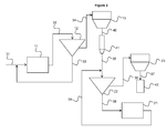
Figure 1 , l'installation de broyage comprend un premier atelier et un second atelier. Le premier atelier comprend un premier broyeur 11, un premier séparateur 12 et un premier filtre 13. Le second atelier comprend un second broyeur 21, un second séparateur 22 et un second filtre 23. Le premier broyeur 11 est alimenté en matière à broyer via un premier moyen de convoyage 31. Une sortie du premier broyeur 11 est reliée à une entrée du premier séparateur 12 par un deuxième moyen de convoyage 32. Une première sortie du premier séparateur 12 est reliée à une entrée du premier broyeur 11 par un troisième moyen de convoyage 33. Une deuxième sortie du premier séparateur 12 est reliée à une entrée du premier filtre 13 par un quatrième moyen de convoyage 34. Une sortie du premier filtre 13 est reliée à une entrée du second séparateur 22 par un cinquième moyen de convoyage 35. Une première sortie du second séparateur 22 est reliée à une entrée du second filtre 23 par un sixième moyen de convoyage 36. Une sortie du filtre 23 est reliée à un moyen de stockage 42 par un septième moyen de convoyage 37. Une deuxième sortie du second séparateur 22 est reliée à une entrée du second broyeur 21 par un huitième moyen de convoyage 38. Une sortie du second broyeur 21 est reliée à l'entrée du second séparateur 22 par un neuvième moyen de convoyage 39. - Les moyens de convoyage peuvent être tout moyen de convoyage connu, et par exemple un tapis transporteur, une vis sans fin ou un camion.
- En ce qui concerne le fonctionnement de l'exemple de réalisation d'une installation de broyage selon la
Figure 1 , le matériau brut est broyé dans le premier broyeur 11 pour fournir un premier matériau broyé. Le premier matériau broyé est séparé dans le premier séparateur 12 pour fournir une première fraction fine et une première fraction grossière. La première fraction grossière est ensuite broyée dans le premier broyeur 11. Le premier filtre 13 est alimenté par la première fraction fine. Le filtrage réalisé par le premier filtre 13 permet de filtrer le gaz de transport du premier séparateur 12 pour fournir une première fraction fine filtrée. La première fraction fine filtrée est séparée dans le second séparateur 22 pour fournir une seconde fraction fine et une seconde fraction grossière. Le second filtre 23 est alimenté par la seconde fraction fine. Le filtrage réalisé par le second filtre 23 permet de filtrer le gaz de transport du second séparateur 22 pour fournir une seconde fraction fine filtrée. La seconde fraction fine filtrée est stockée dans le moyen de stockage 42. La seconde fraction grossière est broyée dans le second broyeur 21 pour fournir un second matériau broyé. Le second matériau broyé est séparé dans le second séparateur 22. - Selon la
Figure 2 , qui représente une variante du procédé représenté dans laFigure 1 , l'installation de broyage peut comprendre, en outre, un moyen de stockage 41, qui peut être un silo, situé entre le premier filtre 13 et le second séparateur 22. La sortie du premier filtre 13 est reliée à une entrée du moyen de stockage 41 par un dixième moyen de convoyage 40. Une sortie du moyen de stockage 41 est reliée à l'entrée du second séparateur 22 par le cinquième moyen de convoyage 35. - En ce qui concerne le fonctionnement de l'exemple de réalisation d'une installation de broyage selon la
Figure 2 , après passage par le premier filtre 13, la première fraction fine filtrée est stockée dans le moyen de stockage 41. Cela peut notamment être le cas quand les deux ateliers ne fonctionnent pas en même temps, ne fonctionnent pas au même débit ou ne sont pas sur le même site. Dans ce dernier cas, le cinquième et/ou le dixième moyen de convoyage 35, 40 est un camion. - A titre d'exemple, le matériau brut à broyer peut avoir une taille de particules inférieure ou égale à 50 mm. La première fraction fine filtrée fournie par le premier filtre 13 peut avoir une taille de particules inférieure ou égale à 80 µm, une surface spécifique Blaine d'environ 3960 cm2/g et une pente de Rosin Rammler d'environ 1,02. La seconde fraction fine filtrée fournie par le second filtre 23 peut avoir une taille de particules inférieure ou égale à 20 µm, une surface spécifique Blaine d'environ 8000 cm2/g et une pente de Rosin Rammler de supérieure ou égale à 1,2.
- A titre d'exemple, le débit de la première fraction fine filtrée fournie par le premier filtre 13 peut être d'environ 100 t/h. Le débit de la seconde fraction fine filtrée fournie par le second filtre 23 peut être d'environ 50 t/h.
- Les
Figures 3 et4 représentent un exemple de réalisation d'un équipement de broyage selon la présente invention. L'équipement de broyage 1 comprend un broyeur 3 et un séparateur 5 reliés entre eux. Le broyeur 3 comprend une enceinte 45 dans laquelle est disposée une table de broyage 2 cylindrique d'axe vertical, entourée par un anneau de soufflage 14 qui comprend des moyens de guidage du flux de gaz selon la direction verticale. Des galets 10 sont posés à la périphérie de la table 2. L'axe des galets 10 est positionné radialement par rapport à la table 2. Un cône 16 relie le broyeur 3 et le séparateur 5. Le broyeur 3 comprend également une première entrée de gaz 7, située dans le bas du broyeur 3 qui débouche dans l'anneau de soufflage 14. L'anneau de soufflage 14 est relié à la première entrée de gaz 7. Un moyen d'approvisionnement en matériau à broyer I permet d'alimenter le broyeur 3 en matériau à broyer. - Le séparateur 5 comprend une enceinte fixe 18 d'axe vertical dans laquelle sont disposées verticalement une cage 9 et des aubes 17. Les aubes 17 sont disposées autour de la cage 9 selon un cercle. Elles s'étendent sur toute la hauteur de la cage 9. La cage 9 comprend des pales 43 fixées entre un disque inférieur plein et un disque supérieur évidé 44. Chaque pale 43 est orientée radialement et s'étend selon une direction substantiellement verticale sur toute la hauteur de la cage 9. Les pales 43 ne se rejoignent pas au centre de la cage 9. Une zone de sélection 15 correspond à l'espace entre la cage 9 et les aubes 17. Une zone d'alimentation 6 en gaz et particules d'un matériau à séparer correspond à l'espace entre l'enceinte cylindrique 18 et les aubes 17. L'enceinte 45 du broyeur 3 débouche à son extrémité supérieure dans la zone d'alimentation 6 par un passage 46. Le séparateur comprend en outre une seconde entrée de gaz 8. La seconde entrée de gaz 8 se situe au niveau de l'enceinte 18 du séparateur 5. La seconde entrée de gaz 8 peut être sous forme de registres à vantelles, dont la position est ajustable pour régler le débit de gaz additionnel. Un moyen de convoyage II permet d'évacuer le matériau broyé final du séparateur 5.
- En fonctionnement, le matériau à broyer est alimenté par le moyen d'approvisionnement I au centre de la table 2 du broyeur 3. La table 2 tourne autour de son axe pendant le broyage. La vitesse de rotation de la table 2 du broyeur 3 peut être fixe ou ajustable. Pendant le broyage, le matériau se déplace depuis le centre de la table 2 vers l'extérieur de la table 2.
- Les galets 10 tournent sur leur axe horizontal. Les galets 10 peuvent avoir différentes formes, par exemple des formes cylindriques, toriques ou tronconiques. Les galets 10 exercent sur la table 2 une pression pendant qu'ils roulent sur la table 2 pour broyer le matériau à broyer. Les galets 10 sont mis en pression par un système hydraulique (fonctionnant par exemple avec de l'huile).
- Le matériau broyé arrivant dans la zone annulaire 14 est transporté par le gaz issu de la première entrée 7 de l'extrémité de la table 2 vers la zone d'alimentation 6 du séparateur 5 par le passage 46. Le débit total de gaz dans la zone d'alimentation 6 comprend deux débits de gaz différents : le débit de gaz issu de la première entrée 7 provenant du broyeur 3 et un débit de gaz additionnel issu de la seconde entrée 8 provenant d'entrées d'air extérieur localisées au niveau du séparateur 5.
- La cage 9 tourne autour de son axe vertical D dans le sens indiqué par la flèche 19. Cette rotation crée une vitesse tangentielle représentée par la flèche 20. Les aubes 17 sont fixes, c'est-à-dire qu'elles ne tournent pas autour de l'axe vertical D de la cage 9. Les aubes 17 sont orientables, par rotation sur elles-mêmes, pour ajuster la vitesse du gaz par rapport à la vitesse de rotation de la cage 9. Le mélange de gaz provenant de la première entrée 7 et de la seconde entée 8, qui transporte les particules du matériau à séparer, arrive par le bas du séparateur et monte substantiellement verticalement dans la zone d'alimentation 6. Il est dévié par les aubes 17, de façon à traverser la zone de sélection 15 et atteindre les pales 43 de la cage 9 selon un mouvement substantiellement radial, c'est-à-dire en direction de l'axe vertical D. Dans la cage 9, le gaz s'échappe selon un mouvement ascendant par une ouverture substantiellement au centre de la cage 9 qui est généralement reliée à un moyen d'aspiration (non représenté). Les particules entraînées par le gaz atteignent la cage 9 avec une vitesse radiale représentée par la flèche 30.
- Le débit de gaz additionnel issu de la seconde entrée 8 permet d'ajuster le débit total de gaz dans la zone d'alimentation 6 et donc le débit de gaz dans la zone de sélection 15. Ce débit total de gaz comprenant le débit de gaz issu de la première entrée 7 et le débit de gaz additionnel issu de la seconde entrée 8 induit la vitesse radiale. La vitesse tangentielle est fixée par la vitesse de rotation de la cage 9 du séparateur 5. La combinaison des vitesses radiale et tangentielle définit la maille de coupure et la finesse du matériau broyé final. Les particules suffisamment petites sont entraînées par le gaz puis remontent substantiellement verticalement avec le gaz. Les particules trop grosses tombent dans la zone de sélection 15 sous l'action de la gravité. Les particules trop grosses qui tombent dans la zone de sélection 15 sont récupérées dans le cône 16, qui envoie les particules trop grosses sur la table 2 du broyeur 3. Les particules fines sont dirigées vers le moyen de convoyage II du matériau broyé final, qui est généralement relié à un moyen d'aspiration et à un moyen de stockage.
Claims (9)
- Equipement de broyage (1) comprenant un broyeur par compression (3) et un séparateur (5), une sortie du séparateur (5) étant reliée à une entrée du broyeur (3), le séparateur (5) étant alimenté en gaz par :• une première entrée de gaz (7) située au niveau du broyeur (3), le gaz issu de la première entrée de gaz (7) traversant d'abord le broyeur (3) puis le séparateur (5) ;• une seconde entrée de gaz (8) située au niveau du séparateur (5), le gaz issu de la seconde entrée de gaz (8) traversant uniquement le séparateur (5) et se mélangeant au gaz issu de la première entrée de gaz (7) après qu'il ait traversé le broyeur (3).
- Installation de broyage comprenant :• un premier atelier comprenant un premier broyeur (11) et un premier séparateur (12), une sortie du premier broyeur (11) étant reliée à une entrée du premier séparateur (12) ;• un second atelier comprenant un second séparateur (22) et un second broyeur (21), une sortie du second séparateur (22) étant reliée à une entrée du second broyeur (21) ;le second séparateur (22) étant alimenté par le matériau issu du premier séparateur (12), caractérisée en ce que :- le second atelier est l'équipement de broyage selon la revendication 1 ;- le premier séparateur (12) fonctionne à une vitesse tangentielle de 15 à 25 m/s et une vitesse radiale de 3,5 à 5 m/s ; et- le second séparateur (22) fonctionne à une vitesse tangentielle de 20 à 50 m/s et une vitesse radiale de 2,5 à 4 m/s.
- Cimenterie comprenant un équipement de broyage selon la revendication 1 ou une installation de broyage selon la revendication 2 relié(e) à une entrée d'un four de cimenterie.
- Atelier de broyage comprenant un équipement de broyage selon la revendication 1 ou une installation de broyage selon la revendication 2 relié(e) à une entrée d'un moyen de stockage.
- Utilisation d'une installation de broyage selon la revendication 2 pour obtenir un matériau broyé final ayant une pente de Rosin Rammler supérieure ou égale à 1,2.
- Procédé de broyage d'un matériau brut dans une installation de broyage selon la revendication 2, comprenant les étapes suivantes :a) broyage du matériau brut à broyer dans le premier broyeur (11) pour fournir un premier matériau broyé ;b) séparation du premier matériau broyé dans le premier séparateur (12) pour fournir une première fraction fine et une première fraction grossière ;c) recirculation de la première fraction grossière vers le premier broyeur (11) ;d) séparation de la première fraction fine dans le second séparateur (22) pour fournir une seconde fraction fine et une seconde fraction grossière ;e) stockage de la seconde fraction fine dans un moyen de stockage (42) ;f) broyage de la seconde fraction grossière dans le second broyeur (21) pour fournir un second matériau broyé ;g) séparation du second matériau broyé dans le second séparateur (22).
- Procédé de fabrication d'un liant hydraulique comprenant les étapes suivantes :(i). Broyage d'au moins deux matériaux dans une installation de broyage selon la revendication 2 ;(ii). Mélange des matériaux obtenus à l'étape (i) avec d'éventuels autres matériaux broyés ou non broyés.
- Procédé selon la revendication 7, dans lequel le broyage de l'étape (i) est une opération pendant laquelle les matériaux sont broyés séparément.
- Liant hydraulique comprenant des matériaux obtenus par broyage dans une installation de broyage selon la revendication 2.
Priority Applications (9)
| Application Number | Priority Date | Filing Date | Title |
|---|---|---|---|
| EP20110306685 EP2604345B1 (fr) | 2011-12-16 | 2011-12-16 | Equipement de broyage |
| DK11306685T DK2604345T3 (da) | 2011-12-16 | 2011-12-16 | Formalingsudstyr |
| US14/365,041 US9114401B2 (en) | 2011-12-16 | 2012-11-30 | Grinding process and unit, and corresponding production process of a hydraulic binder |
| EP12791794.6A EP2790837B1 (fr) | 2011-12-16 | 2012-11-30 | Processus et unité de broyage, et processus correspondant de production d'un liant hydraulique |
| CN201280061343.8A CN103998136B (zh) | 2011-12-16 | 2012-11-30 | 研磨方法和单元和相应的水硬性粘合剂的制备方法 |
| CA2859455A CA2859455C (fr) | 2011-12-16 | 2012-11-30 | Processus et unite de broyage, et processus correspondant de production d'un liant hydraulique |
| PCT/EP2012/074029 WO2013087421A1 (fr) | 2011-12-16 | 2012-11-30 | Processus et unité de broyage, et processus correspondant de production d'un liant hydraulique |
| JP2014546403A JP2015501720A (ja) | 2011-12-16 | 2012-11-30 | 粉砕方法、粉砕設備及び関連する水硬性結合剤の製造方法 |
| ES12791794T ES2744251T3 (es) | 2011-12-16 | 2012-11-30 | Procedimiento y unidad de molienda, y procedimiento de producción correspondiente de un aglutinante hidráulico |
Applications Claiming Priority (1)
| Application Number | Priority Date | Filing Date | Title |
|---|---|---|---|
| EP20110306685 EP2604345B1 (fr) | 2011-12-16 | 2011-12-16 | Equipement de broyage |
Publications (2)
| Publication Number | Publication Date |
|---|---|
| EP2604345A1 true EP2604345A1 (fr) | 2013-06-19 |
| EP2604345B1 EP2604345B1 (fr) | 2014-07-30 |
Family
ID=45478188
Family Applications (1)
| Application Number | Title | Priority Date | Filing Date |
|---|---|---|---|
| EP20110306685 Not-in-force EP2604345B1 (fr) | 2011-12-16 | 2011-12-16 | Equipement de broyage |
Country Status (2)
| Country | Link |
|---|---|
| EP (1) | EP2604345B1 (fr) |
| DK (1) | DK2604345T3 (fr) |
Cited By (2)
| Publication number | Priority date | Publication date | Assignee | Title |
|---|---|---|---|---|
| CN110342839A (zh) * | 2019-07-11 | 2019-10-18 | 杭州中禄新材料有限公司 | 一种水泥生产加工工艺 |
| CN110369046A (zh) * | 2019-07-10 | 2019-10-25 | 宁波可可磁业股份有限公司 | 一种钕铁硼气流磨机的回料设备 |
Families Citing this family (2)
| Publication number | Priority date | Publication date | Assignee | Title |
|---|---|---|---|---|
| LU103190B1 (de) * | 2023-08-25 | 2025-02-25 | Thyssenkrupp Ag | Zweistufiges Vermahlen von Material zur Herstellung eines Bindemittels, insbesondere eines Zements |
| CN121866234A (zh) * | 2023-08-25 | 2026-04-14 | 蒂森克虏伯伯利休斯有限公司 | 用于生产粘结剂(特别是水泥)的物料两级研磨 |
Citations (8)
| Publication number | Priority date | Publication date | Assignee | Title |
|---|---|---|---|---|
| FR604398A (fr) | 1925-10-10 | 1926-05-03 | Outil Mathiaux Et Cie Soc D | Chemise de mandrins pour vilebrequins |
| FR706703A (fr) | 1929-11-30 | 1931-06-29 | Osa Participations Ind | Lampe électrique à décharge, remplie de gaz ou de vapeur |
| FR901364A (fr) | 1943-09-08 | 1945-07-25 | élément d'adhérence pour chaînes antipatinantes | |
| FR1150676A (fr) | 1955-02-07 | 1958-01-16 | Wagner Guenter | Mécanisme cinématique, en particulier pour instruments à écrire à bille |
| US4597537A (en) * | 1982-09-14 | 1986-07-01 | Onoda Cement Company, Ltd. | Vertical mill |
| EP0525423A1 (fr) * | 1991-07-23 | 1993-02-03 | Krupp Polysius Ag | Dispositif et procédé de broyage de matériau avec une granulométrie variable |
| DE4224704A1 (de) * | 1992-07-25 | 1994-01-27 | Zementanlagen Und Maschinenbau | Verfahren und anlagentechnische Schaltung zur Zerkleinerung von Mahlgut, vorzugsweise Zementklinker |
| DE10050332A1 (de) * | 2000-10-11 | 2002-05-02 | Loesche Gmbh | Verfahren und Vorrichtung zur Präparierung von Brennstoffen |
-
2011
- 2011-12-16 DK DK11306685T patent/DK2604345T3/da active
- 2011-12-16 EP EP20110306685 patent/EP2604345B1/fr not_active Not-in-force
Patent Citations (8)
| Publication number | Priority date | Publication date | Assignee | Title |
|---|---|---|---|---|
| FR604398A (fr) | 1925-10-10 | 1926-05-03 | Outil Mathiaux Et Cie Soc D | Chemise de mandrins pour vilebrequins |
| FR706703A (fr) | 1929-11-30 | 1931-06-29 | Osa Participations Ind | Lampe électrique à décharge, remplie de gaz ou de vapeur |
| FR901364A (fr) | 1943-09-08 | 1945-07-25 | élément d'adhérence pour chaînes antipatinantes | |
| FR1150676A (fr) | 1955-02-07 | 1958-01-16 | Wagner Guenter | Mécanisme cinématique, en particulier pour instruments à écrire à bille |
| US4597537A (en) * | 1982-09-14 | 1986-07-01 | Onoda Cement Company, Ltd. | Vertical mill |
| EP0525423A1 (fr) * | 1991-07-23 | 1993-02-03 | Krupp Polysius Ag | Dispositif et procédé de broyage de matériau avec une granulométrie variable |
| DE4224704A1 (de) * | 1992-07-25 | 1994-01-27 | Zementanlagen Und Maschinenbau | Verfahren und anlagentechnische Schaltung zur Zerkleinerung von Mahlgut, vorzugsweise Zementklinker |
| DE10050332A1 (de) * | 2000-10-11 | 2002-05-02 | Loesche Gmbh | Verfahren und Vorrichtung zur Präparierung von Brennstoffen |
Cited By (2)
| Publication number | Priority date | Publication date | Assignee | Title |
|---|---|---|---|---|
| CN110369046A (zh) * | 2019-07-10 | 2019-10-25 | 宁波可可磁业股份有限公司 | 一种钕铁硼气流磨机的回料设备 |
| CN110342839A (zh) * | 2019-07-11 | 2019-10-18 | 杭州中禄新材料有限公司 | 一种水泥生产加工工艺 |
Also Published As
| Publication number | Publication date |
|---|---|
| EP2604345B1 (fr) | 2014-07-30 |
| DK2604345T3 (da) | 2014-09-08 |
Similar Documents
| Publication | Publication Date | Title |
|---|---|---|
| CN103998136B (zh) | 研磨方法和单元和相应的水硬性粘合剂的制备方法 | |
| JP5634198B2 (ja) | 砕砂、砕石生産システム | |
| JP5576510B2 (ja) | 金属回収のためのステンレス鋼スラグおよび鉄鋼スラグの精製方法 | |
| EP2604345B1 (fr) | Equipement de broyage | |
| CN110090719B (zh) | 一种粒径分级装置及系统 | |
| EP2106294B1 (fr) | Appareil de sélection granulométrique et/ou de séchage de matière | |
| JP5264846B2 (ja) | 砕石および砕砂の製造プラントおよび製造方法 | |
| JPWO2003066220A1 (ja) | 粉砕方法 | |
| EP2604346B1 (fr) | Installation de broyage | |
| EP2718028A2 (fr) | Séparateur dynamique pour matériaux pulvérulents | |
| CA2797004A1 (fr) | Procede et installation de broyage d'une matiere minerale contenant au moins du calcium et des impuretes metalliques | |
| KR100507705B1 (ko) | 모래제조장치 | |
| JP5857629B2 (ja) | バイオマスミル | |
| FR2670135A1 (fr) | Procede de broyage de matieres cassantes comportant pour la mise en óoeuvre du procede une desagglomeration selective et installation. | |
| JPH0515805A (ja) | 粉砕設備 | |
| JP2001224973A (ja) | 砕砂製造用竪型粉砕機 | |
| CN220160055U (zh) | 一种化工制造用原料研磨机 | |
| JPH05285411A (ja) | 砕砂ダスト除去装置 | |
| JPH05285455A (ja) | 砕砂ダスト除去装置 | |
| JPH10230179A (ja) | 竪型ローラミルによるセメントクリンカの粉砕方法および装置 | |
| RU2472593C1 (ru) | Устройство для сухого обогащения минерального сырья | |
| JP5810542B2 (ja) | バイオマスミル | |
| JP3211420B2 (ja) | 分級装置 | |
| JP3805131B2 (ja) | 砕砂製造用竪型粉砕機の運転方法 | |
| JP2792577B2 (ja) | 竪型粉砕機 |
Legal Events
| Date | Code | Title | Description |
|---|---|---|---|
| PUAI | Public reference made under article 153(3) epc to a published international application that has entered the european phase |
Free format text: ORIGINAL CODE: 0009012 |
|
| AK | Designated contracting states |
Kind code of ref document: A1 Designated state(s): AL AT BE BG CH CY CZ DE DK EE ES FI FR GB GR HR HU IE IS IT LI LT LU LV MC MK MT NL NO PL PT RO RS SE SI SK SM TR |
|
| AX | Request for extension of the european patent |
Extension state: BA ME |
|
| 17P | Request for examination filed |
Effective date: 20131219 |
|
| RBV | Designated contracting states (corrected) |
Designated state(s): AL AT BE BG CH CY CZ DE DK EE ES FI FR GB GR HR HU IE IS IT LI LT LU LV MC MK MT NL NO PL PT RO RS SE SI SK SM TR |
|
| GRAP | Despatch of communication of intention to grant a patent |
Free format text: ORIGINAL CODE: EPIDOSNIGR1 |
|
| INTG | Intention to grant announced |
Effective date: 20140313 |
|
| GRAS | Grant fee paid |
Free format text: ORIGINAL CODE: EPIDOSNIGR3 |
|
| GRAA | (expected) grant |
Free format text: ORIGINAL CODE: 0009210 |
|
| AK | Designated contracting states |
Kind code of ref document: B1 Designated state(s): AL AT BE BG CH CY CZ DE DK EE ES FI FR GB GR HR HU IE IS IT LI LT LU LV MC MK MT NL NO PL PT RO RS SE SI SK SM TR |
|
| REG | Reference to a national code |
Ref country code: GB Ref legal event code: FG4D Free format text: NOT ENGLISH |
|
| REG | Reference to a national code |
Ref country code: CH Ref legal event code: EP |
|
| REG | Reference to a national code |
Ref country code: AT Ref legal event code: REF Ref document number: 679683 Country of ref document: AT Kind code of ref document: T Effective date: 20140815 |
|
| REG | Reference to a national code |
Ref country code: IE Ref legal event code: FG4D Free format text: LANGUAGE OF EP DOCUMENT: FRENCH |
|
| REG | Reference to a national code |
Ref country code: DK Ref legal event code: T3 Effective date: 20140902 |
|
| REG | Reference to a national code |
Ref country code: DE Ref legal event code: R096 Ref document number: 602011008705 Country of ref document: DE Effective date: 20140911 |
|
| REG | Reference to a national code |
Ref country code: NL Ref legal event code: VDEP Effective date: 20140730 |
|
| REG | Reference to a national code |
Ref country code: LT Ref legal event code: MG4D |
|
| PG25 | Lapsed in a contracting state [announced via postgrant information from national office to epo] |
Ref country code: GR Free format text: LAPSE BECAUSE OF FAILURE TO SUBMIT A TRANSLATION OF THE DESCRIPTION OR TO PAY THE FEE WITHIN THE PRESCRIBED TIME-LIMIT Effective date: 20141031 Ref country code: BG Free format text: LAPSE BECAUSE OF FAILURE TO SUBMIT A TRANSLATION OF THE DESCRIPTION OR TO PAY THE FEE WITHIN THE PRESCRIBED TIME-LIMIT Effective date: 20141030 Ref country code: LT Free format text: LAPSE BECAUSE OF FAILURE TO SUBMIT A TRANSLATION OF THE DESCRIPTION OR TO PAY THE FEE WITHIN THE PRESCRIBED TIME-LIMIT Effective date: 20140730 Ref country code: FI Free format text: LAPSE BECAUSE OF FAILURE TO SUBMIT A TRANSLATION OF THE DESCRIPTION OR TO PAY THE FEE WITHIN THE PRESCRIBED TIME-LIMIT Effective date: 20140730 Ref country code: NO Free format text: LAPSE BECAUSE OF FAILURE TO SUBMIT A TRANSLATION OF THE DESCRIPTION OR TO PAY THE FEE WITHIN THE PRESCRIBED TIME-LIMIT Effective date: 20141030 Ref country code: PT Free format text: LAPSE BECAUSE OF FAILURE TO SUBMIT A TRANSLATION OF THE DESCRIPTION OR TO PAY THE FEE WITHIN THE PRESCRIBED TIME-LIMIT Effective date: 20141202 Ref country code: ES Free format text: LAPSE BECAUSE OF FAILURE TO SUBMIT A TRANSLATION OF THE DESCRIPTION OR TO PAY THE FEE WITHIN THE PRESCRIBED TIME-LIMIT Effective date: 20140730 Ref country code: SE Free format text: LAPSE BECAUSE OF FAILURE TO SUBMIT A TRANSLATION OF THE DESCRIPTION OR TO PAY THE FEE WITHIN THE PRESCRIBED TIME-LIMIT Effective date: 20140730 |
|
| PG25 | Lapsed in a contracting state [announced via postgrant information from national office to epo] |
Ref country code: PL Free format text: LAPSE BECAUSE OF FAILURE TO SUBMIT A TRANSLATION OF THE DESCRIPTION OR TO PAY THE FEE WITHIN THE PRESCRIBED TIME-LIMIT Effective date: 20140730 Ref country code: NL Free format text: LAPSE BECAUSE OF FAILURE TO SUBMIT A TRANSLATION OF THE DESCRIPTION OR TO PAY THE FEE WITHIN THE PRESCRIBED TIME-LIMIT Effective date: 20140730 Ref country code: IS Free format text: LAPSE BECAUSE OF FAILURE TO SUBMIT A TRANSLATION OF THE DESCRIPTION OR TO PAY THE FEE WITHIN THE PRESCRIBED TIME-LIMIT Effective date: 20141130 Ref country code: RS Free format text: LAPSE BECAUSE OF FAILURE TO SUBMIT A TRANSLATION OF THE DESCRIPTION OR TO PAY THE FEE WITHIN THE PRESCRIBED TIME-LIMIT Effective date: 20140730 Ref country code: LV Free format text: LAPSE BECAUSE OF FAILURE TO SUBMIT A TRANSLATION OF THE DESCRIPTION OR TO PAY THE FEE WITHIN THE PRESCRIBED TIME-LIMIT Effective date: 20140730 Ref country code: CY Free format text: LAPSE BECAUSE OF FAILURE TO SUBMIT A TRANSLATION OF THE DESCRIPTION OR TO PAY THE FEE WITHIN THE PRESCRIBED TIME-LIMIT Effective date: 20140730 Ref country code: HR Free format text: LAPSE BECAUSE OF FAILURE TO SUBMIT A TRANSLATION OF THE DESCRIPTION OR TO PAY THE FEE WITHIN THE PRESCRIBED TIME-LIMIT Effective date: 20140730 |
|
| PG25 | Lapsed in a contracting state [announced via postgrant information from national office to epo] |
Ref country code: IT Free format text: LAPSE BECAUSE OF FAILURE TO SUBMIT A TRANSLATION OF THE DESCRIPTION OR TO PAY THE FEE WITHIN THE PRESCRIBED TIME-LIMIT Effective date: 20140730 Ref country code: EE Free format text: LAPSE BECAUSE OF FAILURE TO SUBMIT A TRANSLATION OF THE DESCRIPTION OR TO PAY THE FEE WITHIN THE PRESCRIBED TIME-LIMIT Effective date: 20140730 Ref country code: RO Free format text: LAPSE BECAUSE OF FAILURE TO SUBMIT A TRANSLATION OF THE DESCRIPTION OR TO PAY THE FEE WITHIN THE PRESCRIBED TIME-LIMIT Effective date: 20140730 Ref country code: SK Free format text: LAPSE BECAUSE OF FAILURE TO SUBMIT A TRANSLATION OF THE DESCRIPTION OR TO PAY THE FEE WITHIN THE PRESCRIBED TIME-LIMIT Effective date: 20140730 Ref country code: CZ Free format text: LAPSE BECAUSE OF FAILURE TO SUBMIT A TRANSLATION OF THE DESCRIPTION OR TO PAY THE FEE WITHIN THE PRESCRIBED TIME-LIMIT Effective date: 20140730 |
|
| REG | Reference to a national code |
Ref country code: DE Ref legal event code: R097 Ref document number: 602011008705 Country of ref document: DE |
|
| PLBE | No opposition filed within time limit |
Free format text: ORIGINAL CODE: 0009261 |
|
| STAA | Information on the status of an ep patent application or granted ep patent |
Free format text: STATUS: NO OPPOSITION FILED WITHIN TIME LIMIT |
|
| PG25 | Lapsed in a contracting state [announced via postgrant information from national office to epo] |
Ref country code: BE Free format text: LAPSE BECAUSE OF NON-PAYMENT OF DUE FEES Effective date: 20141231 |
|
| 26N | No opposition filed |
Effective date: 20150504 |
|
| PG25 | Lapsed in a contracting state [announced via postgrant information from national office to epo] |
Ref country code: LU Free format text: LAPSE BECAUSE OF FAILURE TO SUBMIT A TRANSLATION OF THE DESCRIPTION OR TO PAY THE FEE WITHIN THE PRESCRIBED TIME-LIMIT Effective date: 20141216 |
|
| REG | Reference to a national code |
Ref country code: CH Ref legal event code: PL |
|
| REG | Reference to a national code |
Ref country code: IE Ref legal event code: MM4A |
|
| PG25 | Lapsed in a contracting state [announced via postgrant information from national office to epo] |
Ref country code: IE Free format text: LAPSE BECAUSE OF NON-PAYMENT OF DUE FEES Effective date: 20141216 Ref country code: LI Free format text: LAPSE BECAUSE OF NON-PAYMENT OF DUE FEES Effective date: 20141231 Ref country code: CH Free format text: LAPSE BECAUSE OF NON-PAYMENT OF DUE FEES Effective date: 20141231 |
|
| PG25 | Lapsed in a contracting state [announced via postgrant information from national office to epo] |
Ref country code: SI Free format text: LAPSE BECAUSE OF FAILURE TO SUBMIT A TRANSLATION OF THE DESCRIPTION OR TO PAY THE FEE WITHIN THE PRESCRIBED TIME-LIMIT Effective date: 20140730 |
|
| REG | Reference to a national code |
Ref country code: FR Ref legal event code: PLFP Year of fee payment: 5 |
|
| PG25 | Lapsed in a contracting state [announced via postgrant information from national office to epo] |
Ref country code: SM Free format text: LAPSE BECAUSE OF FAILURE TO SUBMIT A TRANSLATION OF THE DESCRIPTION OR TO PAY THE FEE WITHIN THE PRESCRIBED TIME-LIMIT Effective date: 20140730 |
|
| PG25 | Lapsed in a contracting state [announced via postgrant information from national office to epo] |
Ref country code: MC Free format text: LAPSE BECAUSE OF FAILURE TO SUBMIT A TRANSLATION OF THE DESCRIPTION OR TO PAY THE FEE WITHIN THE PRESCRIBED TIME-LIMIT Effective date: 20140730 |
|
| PG25 | Lapsed in a contracting state [announced via postgrant information from national office to epo] |
Ref country code: TR Free format text: LAPSE BECAUSE OF FAILURE TO SUBMIT A TRANSLATION OF THE DESCRIPTION OR TO PAY THE FEE WITHIN THE PRESCRIBED TIME-LIMIT Effective date: 20140730 Ref country code: HU Free format text: LAPSE BECAUSE OF FAILURE TO SUBMIT A TRANSLATION OF THE DESCRIPTION OR TO PAY THE FEE WITHIN THE PRESCRIBED TIME-LIMIT; INVALID AB INITIO Effective date: 20111216 Ref country code: MT Free format text: LAPSE BECAUSE OF FAILURE TO SUBMIT A TRANSLATION OF THE DESCRIPTION OR TO PAY THE FEE WITHIN THE PRESCRIBED TIME-LIMIT Effective date: 20140730 |
|
| GBPC | Gb: european patent ceased through non-payment of renewal fee |
Effective date: 20151216 |
|
| PG25 | Lapsed in a contracting state [announced via postgrant information from national office to epo] |
Ref country code: GB Free format text: LAPSE BECAUSE OF NON-PAYMENT OF DUE FEES Effective date: 20151216 |
|
| REG | Reference to a national code |
Ref country code: FR Ref legal event code: PLFP Year of fee payment: 6 |
|
| REG | Reference to a national code |
Ref country code: FR Ref legal event code: PLFP Year of fee payment: 7 |
|
| PG25 | Lapsed in a contracting state [announced via postgrant information from national office to epo] |
Ref country code: MK Free format text: LAPSE BECAUSE OF FAILURE TO SUBMIT A TRANSLATION OF THE DESCRIPTION OR TO PAY THE FEE WITHIN THE PRESCRIBED TIME-LIMIT Effective date: 20140730 |
|
| REG | Reference to a national code |
Ref country code: AT Ref legal event code: PC Ref document number: 679683 Country of ref document: AT Kind code of ref document: T Owner name: HOLCIM TECHNOLOGY LTD, CH Effective date: 20180730 |
|
| REG | Reference to a national code |
Ref country code: DE Ref legal event code: R081 Ref document number: 602011008705 Country of ref document: DE Owner name: HOLCIM TECHNOLOGY LTD., CH Free format text: FORMER OWNER: LAFARGE, PARIS, FR |
|
| PG25 | Lapsed in a contracting state [announced via postgrant information from national office to epo] |
Ref country code: AL Free format text: LAPSE BECAUSE OF FAILURE TO SUBMIT A TRANSLATION OF THE DESCRIPTION OR TO PAY THE FEE WITHIN THE PRESCRIBED TIME-LIMIT Effective date: 20140730 |
|
| PGFP | Annual fee paid to national office [announced via postgrant information from national office to epo] |
Ref country code: FR Payment date: 20191226 Year of fee payment: 9 |
|
| PGFP | Annual fee paid to national office [announced via postgrant information from national office to epo] |
Ref country code: AT Payment date: 20191029 Year of fee payment: 9 |
|
| PGFP | Annual fee paid to national office [announced via postgrant information from national office to epo] |
Ref country code: DE Payment date: 20191231 Year of fee payment: 9 Ref country code: DK Payment date: 20191230 Year of fee payment: 9 |
|
| REG | Reference to a national code |
Ref country code: DE Ref legal event code: R119 Ref document number: 602011008705 Country of ref document: DE |
|
| REG | Reference to a national code |
Ref country code: DK Ref legal event code: EBP Effective date: 20201231 |
|
| REG | Reference to a national code |
Ref country code: AT Ref legal event code: MM01 Ref document number: 679683 Country of ref document: AT Kind code of ref document: T Effective date: 20201216 |
|
| PG25 | Lapsed in a contracting state [announced via postgrant information from national office to epo] |
Ref country code: AT Free format text: LAPSE BECAUSE OF NON-PAYMENT OF DUE FEES Effective date: 20201216 Ref country code: FR Free format text: LAPSE BECAUSE OF NON-PAYMENT OF DUE FEES Effective date: 20201231 |
|
| PG25 | Lapsed in a contracting state [announced via postgrant information from national office to epo] |
Ref country code: DE Free format text: LAPSE BECAUSE OF NON-PAYMENT OF DUE FEES Effective date: 20210701 |
|
| PG25 | Lapsed in a contracting state [announced via postgrant information from national office to epo] |
Ref country code: DK Free format text: LAPSE BECAUSE OF NON-PAYMENT OF DUE FEES Effective date: 20201231 |