EP2605380A2 - Machine électrique rotative, véhicule ferroviaire et véhicule électrique équipé de celui-ci - Google Patents
Machine électrique rotative, véhicule ferroviaire et véhicule électrique équipé de celui-ci Download PDFInfo
- Publication number
- EP2605380A2 EP2605380A2 EP12197185.7A EP12197185A EP2605380A2 EP 2605380 A2 EP2605380 A2 EP 2605380A2 EP 12197185 A EP12197185 A EP 12197185A EP 2605380 A2 EP2605380 A2 EP 2605380A2
- Authority
- EP
- European Patent Office
- Prior art keywords
- rotor
- stator
- iron core
- rotating electric
- electric machine
- Prior art date
- Legal status (The legal status is an assumption and is not a legal conclusion. Google has not performed a legal analysis and makes no representation as to the accuracy of the status listed.)
- Granted
Links
Images


Classifications
-
- H—ELECTRICITY
- H02—GENERATION; CONVERSION OR DISTRIBUTION OF ELECTRIC POWER
- H02K—DYNAMO-ELECTRIC MACHINES
- H02K9/00—Arrangements for cooling or ventilating
- H02K9/02—Arrangements for cooling or ventilating by ambient air flowing through the machine
- H02K9/04—Arrangements for cooling or ventilating by ambient air flowing through the machine having means for generating a flow of cooling medium
- H02K9/06—Arrangements for cooling or ventilating by ambient air flowing through the machine having means for generating a flow of cooling medium with fans or impellers driven by the machine shaft
-
- H—ELECTRICITY
- H02—GENERATION; CONVERSION OR DISTRIBUTION OF ELECTRIC POWER
- H02K—DYNAMO-ELECTRIC MACHINES
- H02K1/00—Details of the magnetic circuit
- H02K1/06—Details of the magnetic circuit characterised by the shape, form or construction
- H02K1/22—Rotating parts of the magnetic circuit
- H02K1/32—Rotating parts of the magnetic circuit with channels or ducts for flow of cooling medium
-
- H—ELECTRICITY
- H02—GENERATION; CONVERSION OR DISTRIBUTION OF ELECTRIC POWER
- H02K—DYNAMO-ELECTRIC MACHINES
- H02K9/00—Arrangements for cooling or ventilating
- H02K9/10—Arrangements for cooling or ventilating by gaseous cooling medium flowing in closed circuit, a part of which is external to the machine casing
-
- Y—GENERAL TAGGING OF NEW TECHNOLOGICAL DEVELOPMENTS; GENERAL TAGGING OF CROSS-SECTIONAL TECHNOLOGIES SPANNING OVER SEVERAL SECTIONS OF THE IPC; TECHNICAL SUBJECTS COVERED BY FORMER USPC CROSS-REFERENCE ART COLLECTIONS [XRACs] AND DIGESTS
- Y02—TECHNOLOGIES OR APPLICATIONS FOR MITIGATION OR ADAPTATION AGAINST CLIMATE CHANGE
- Y02T—CLIMATE CHANGE MITIGATION TECHNOLOGIES RELATED TO TRANSPORTATION
- Y02T10/00—Road transport of goods or passengers
- Y02T10/60—Other road transportation technologies with climate change mitigation effect
- Y02T10/64—Electric machine technologies in electromobility
Definitions
- the present invention relates to rotating electric machines, and rail vehicles and electric vehicles equipped therewith, and particularly to rotating electric machines suitable to be cooled with air inside the machine and air outside the machine, and rail vehicles and electric vehicles equipped therewith.
- cooling methods for rotating electric machines include three methods, that is, cooling by circulating air inside the machine (inside air) by means of an inner fan arranged inside the machine, cooling by ventilating air outside the machine (outside air) around the outer surface of the machine by means of an outer fan arranged outside the machine, and using the former and the latter together.
- Cooling methods for rotating electric machines disclosed in Japanese Patent Laid-open No. 2003-143809 (PTL 1) and Japanese Patent Laid-Open No. Hei 9(1997)-149599 (PTL 2) are characterized in that cooling method by circulating inside air by means of an inner fan arranged inside the machine and cooling method by ventilating outside air around the outer surface of the machine by means of an outer fan arranged outside the machine are used together, and cooling methods for rotating electric machines disclosed in Japanese Patent Laid-open No. 2006-271081 (PTL 3) and Japanese Patent Laid-Open No. Hei 6(1994)-6958 (PTL 4) are characterized in that outside air is ventilated around the inner circumference part of the machine.
- the present invention is performed in view of the problems described above, and the object is to provide a rotating electric machine, in which not only inside air but also the coil end part of the stator are prevented from becoming high in temperature, the permanent magnet is prevented from causing demagnetization at high temperature in the case of permanent magnet type, and the cooling performance is improved, and a rail vehicle and an electric vehicle equipped with the rotating electric machine.
- a rotating electric machine of the present invention is made up of a stator and a rotor oppositely arranged through the intervention of predetermined air gap at the inner diameter side of the stator;
- the stator has a stator iron core, a plurality of stator slots that extend in the axial direction and are formed in the circumferential direction at predetermined intervals at the inner diameter side of the stator iron core, and stator coils attached in the plurality of stator slots;
- the rotor has a rotor iron core, a plurality of rotor slots that extend in the axial direction and are formed in the circumferential direction at predetermined intervals at the outer circumference side of the rotor iron core, and magnetic field members inserted in the rotor slots; and/or the rotor iron core has outside air ventilation holes for ventilating air outside the machine and inside air ventilation holes for ventilating air inside the machine.
- a rail vehicle of the present invention has a truck, a rotating electric machine, a speed increasing gear, and wheels, the rotating electric machine drives the wheels via the speed increasing gear, and the rotating electric machine has the construction described above.
- an electric vehicle of the present invention has a body, wheels, an axle, and a rotating electric machine, the rotating electric machine directly connected to the axle drives the wheels, and the rotating electric machine has the construction described above.
- the present invention can contribute to miniaturization of rotating electric machines because not only inside air but also the coil end part of the stator are prevented from becoming high in temperature, the permanent magnet is also prevented from causing demagnetization at high temperature in the case of permanent magnet type, and the cooling performance is improved.
- rail vehicles and electric vehicles with larger output power can be obtained by being equipped with the miniaturized rotating electric machines.
- FIGs. 1 and 2 an induction motor is shown as embodiment 1 of the rotating electric machines of the invention.
- housing is not shown in the drawing.
- a rotating electric machine 1 that is an induction motor, is made up of a stator 2 and a rotor 3.
- the stator 2 is roughly made up of a stator iron core 4, a poly-phase winding wire 5 wound around a plurality of stator slots 12 that are arranged at the inner circumference side of the stator iron core 4, formed at predetermined intervals in the circumferential direction, and extend in the axial direction, and a housing 11 that retains the stator iron core 4 at the inner circumference surface.
- the stator iron core 4 made of laminated plural electromagnetic steel sheets has a cylindrical yoke part 21 (or referred to as core back part), a plurality of teeth parts 22 that project from the inner circumference surface of the yoke part 21 to the inner side of the diameter direction and extend in the axial direction along the inner circumference surface of the yoke part 21.
- the teeth parts 22 are arranged at regular intervals in the circumferential direction along the inner circumference surface of the yoke part 21. Also, between the teeth parts 22 of the stator 2, the stator slots 12 around which the winding wire 5 described above is wound.
- the rotor 3 is roughly made up of a rotor iron core 7 arranged at a predetermined distance from the stator iron core 4 in the diameter direction and made of laminated plural electromagnetic steel sheets, rotor bars 13, which are magnetic field members, inserted in a plurality of the rotor slots 6 that are arranged at the outer circumference side of the rotor iron core 7, formed at predetermined intervals in the circumferential direction, and extend in the axial direction, endrings 14 made up of conductors that short-circuit each of the rotor bars 13 at the both axial end, a shaft 8 engaged with the rotor iron core 7, and the shaft 8 is rotatably retained by a bearing 10.
- the rotor iron core 7 is fixed in the axial direction by a holding plate 15 for holding the rotor iron core 7, and the rotor 3 is equipped with an inner fan 50 for inside air ventilation and an outer fan 51 for outside air ventilation.
- the bearing 10 is supported by an end bracket 9, and the end bracket 9 is fixed to the housing 11.
- the rotor 3 rotates in a clockwise direction or in a counterclockwise direction, and is driven as a motor.
- a plurality of holes 16 for outside air ventilation that ventilate outside air and, at the outside of the holes 16, a plurality of holes 17a for inside air ventilation that ventilate inside air are formed with having predetermined intervals in the circumferential direction and passing through in the axial direction in the rotor iron core 7 of the rotor 3.
- the holes 16 for outside air ventilation and the holes 17a for inside air ventilation that ventilate inside air are similarly formed in the holding plate 15 for holding the rotor iron core 7.
- the holes 16 for outside air ventilation are located at the inner circumference side of the rotor 3 than the holes 17a for inside air ventilation.
- the rotor iron core 7 has a structure in which the holes 16 for outside air ventilation, the holes 17a for inside air ventilation, the rotor slots 6, and the hole of the shaft 8 are punched out. And the electromagnetic steel sheets through which the holes 16 for outside air ventilation, the holes 17a for inside air ventilation, the rotor slots 6, and the hole of the shaft 8 are punched and laminated, and the rotor bars 13 and the shaft 8 are inserted into the rotor slots 6 passing through the sheets and the hole for passing the shaft 8 respectively to compose the rotor 3.
- a ventilation route (cooling route) in which inside air and outside air are used according to the embodiment is described by using Fig. 1 .
- outside air 56 is inhaled from an outside air inlet 54 by an outer fan 51 to enter an air stagnation part 52, and dust is exhausted from a dust outlet 53 by centrifugal force caused by the outer fan 51.
- the outside air 56 from which dust is removed is passed through the holes 16 for outside air ventilation and exhausted from an outside air outlet 55 by the outer fan 51.
- the outside air 56 cools the rotor iron core 7, the rotor bars 13, and inside air 57 through the rotor iron core 7.
- the inside air 57 is passed through the coil end 18 that is located at the end in the axial direction of the winding wire 5 and endring 14, and is moved to duct 17b for inside air ventilation by the inner fan 50.
- the inside air 57 cools the coil end 18 and the endring 14.
- the inside air 57 passes through the duct 17b for inside air ventilation, and passes through the coil end 18 and the endring 14 that are located at the opposite end in the axial direction.
- the inside air 57 is cooled by the outside air 56 through the housing 11.
- the inside air 57 cooled by the outside air 56 cools the coil end 18 and the endring 14.
- the inside air 57 that passed through the coil end 18 and the endring 14 passes through the duct 17a for inside air ventilation to circulate in the machine.
- the inside air 57 cools the rotator bar 13 through the rotor iron core 7 (by heat conduction).
- the inside air 57 is cooled by heat exchange through the rotor iron core 7 with the outside air 56 that is ventilated in the holes 16 for outside air ventilation.
- the inside air 57 cools the coil end 18 and the endring 14, and the outside air 56 cools the rotor iron core 7 and the rotator bars 13 of the rotor 3 and the inside air 57.
- Structure of the embodiment described above can contribute to miniaturization of rotating electric machines because not only the inside air but also the coil end part of the stator are prevented from becoming high in temperature, and the cooling performance is improved.
- the embodiment air temperature is reduced, and rotating electric machines can be miniaturized accordingly.
- the embodiment since length in the diameter direction can be reduced when length in the axial direction is the same, and length in the axial direction can be reduced when length in the diameter direction is the same, the embodiment can contribute to miniaturization of rotating electric machines.
- a plurality of holes 16 for outside air ventilation and a plurality of holes 17a for inside air ventilation are formed in the circumferential direction at predetermined intervals, but the effect can be achieved with at least each one of these two types of holes.
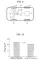
- Fig. 10 reduction effect of temperature rise at the coil end is shown when embodiment 1 of the invention that has holes for outside air ventilation is compared with conventional art that has no holes for outside air ventilation.
- embodiment 1 of the invention that has holes for outside air ventilation can reduce the temperature rise at the coil end by about 14K compared with conventional art that has no holes for outside air ventilation.
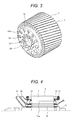
- FIG. 3 a stator 2, a housing 11, a shaft 8, a bearing 10, rotor bars 13, and an endring 14 are not shown.
- embodiment 2 differences of embodiment 2 from embodiment 1 are that a rotor iron core 7 is skewed in the circumferential direction, and vanes 20 are fixed to the holding plate 15 around holes 16 for outside air ventilation and holes 17a for inside air ventilation.
- Reference number 19 is a shaft hole.
- the embodiment described above since the rotor iron core 7 is skewed and the vanes 20 are fixed to the holding plate 15, when the rotor 3 rotates, air is introduced into the holes 16 for outside air ventilation and the holes 17a for inside air ventilation by the vanes 20.
- the holes 16 for outside air ventilation and the holes 17a for inside air ventilation are also skewed, whereby air resistance can be reduced to increase airflow rate.
- the embodiment can achieve a structure without an inner fan 50 for inside air ventilation and an outer fan 51 for outside air ventilation and obtain the similar effects as embodiment 1 to contribute to further miniaturization of rotating electric machines.
- FIG. 4 a stator 2, a bearing 10, and a housing 11 are not shown.
- an inner fan 50 and an outer fan 51 that are fixed to a rotor iron core 7 form an integral structure.
- the integral inner fan 50 and outer fan 51 are attached to the holding plate 15.
- FIG. 5 a stator 2, a bearing 10, and a housing 11 are not shown.
- an inner fan 50 and an outer fan 51 which are fixed to holding plates 15 of a rotor iron core 7, are respectively located at one end in the axial direction of a rotor 3 and at the opposite end in the axial direction of the rotor 3.
- the inner fan 50 and the outer fan 51 may be respectively composed with the holding plates 15 that are placed at both ends in the axial direction of the rotor iron core 7 for pressing the rotor iron core 7 from the axial direction.
- FIG. 6 a stator 2, a bearing 10, a housing 11, and an outer fan 51 are not shown.
- a difference of embodiment 5 from embodiment 1 is that holes 16 for outside air ventilation are arranged at the outer circumference side of the rotor 3 than holes 17a for inside air ventilation.
- the holding plate 15 has a diagonal through hole 15a from the inner circumference side to the outer circumference side in the diameter direction, and the outside air is ventilated into the holes 16 for outside air ventilation arranged at the outer circumference side of the rotor 3. And the outside air that passed through the holes 16 for outside air ventilation is ventilated into the holding plate 15 at the opposite side in the axial direction, and is exhausted through diagonal through holes 15b from the outer circumference side to the inner circumference side in the diameter direction to the outside of the machine.
- inside air that is circulated by an inner fan 50 is ventilated through the holding plate 15 that has diagonal through holes 15c from the outer circumference side to the inner circumference side in the diameter direction into the holes 17a for inside air ventilation arranged at the inner circumference side of the rotor 3.
- the inside air that passed through the holes 17a for inside air ventilation is ventilated through the holding plate 15 at the opposite side in the axial direction that has a diagonal through hole 15d from the inner circumference side to the outer circumference side in the diameter direction.
- cooling performance of rotating electric machines can be improved because not only the similar effects as embodiment 1 are obtained but also holes 17a for inside air ventilation can be placed near rotor bars 13 that generate large amount of heat to cool the rotor bars 13 effectively.
- Fig. 7 the rotating electric machine according to the invention is a permanent magnet motor.
- a difference of embodiment 6 from embodiment 1 is that rotor bars are used in a rotor 3 as an example of an induction motor in embodiment 1, but permanent magnets 23 are used in the rotor 3 in this embodiment.
- a plurality of the permanent magnets 23, which are magnetic field members, are arranged in magnet insertion holes of a rotor iron core 7 in such a way that the permanent magnets 23 have predetermined intervals in the circumferential direction and extend in the axial direction.
- Other structures are similar to the structures of Fig. 1 .
- cooling performance of permanent magnet motors can be improved because not only the similar effects as embodiment 1 are obtained but also outside air 56 passes through holes 16 for outside air ventilation and inside air 57 passes through holes 17a for inside air ventilation to control heat generation of permanent magnets 23, whereby fear of demagnetization at high temperature of the permanent magnets 23 is eliminated and, in addition, the inside air 57 is cooled.
- the present invention is applicable to both distributed winding type rotating electric machines and concentrated winding type rotating electric machines.
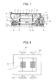
- a rail vehicle equipped with a rotating electric machine of any one of embodiments described above according to the invention is described by using Fig. 8 .
- a rail vehicle 200 is made up of a truck 201 equipped with a rotating electric machine 1 of any one of the embodiments 1 to 6, a speed increasing gear 202, and wheels 203, and the rotating electric machine 1 drives the wheels 203 via the speed increasing gear 202.
- rotating electric machines 1 are installed, but one or more than two rotating electric machines 1 may be installed for driving.
- the rotating electric machines 1 are described to be used for driving the wheels 203 of the rail vehicle, but the rotating electric machines 1 can be used in electric operation construction machine drive units and all other drive units.
- a body 100 of the electric automobile is supported with four wheels 110, 112, 114, and 116. Since the electric automobile is a front-wheel drive automobile, a rotating electric machine of any one of embodiments 1 to 6 is directly connected to anterior axle 154.
- Driving torque of the rotating electric machine 1 is controlled by a control device 130.
- a battery 151 is installed, electric power is supplied from the battery 151 through the control device 130 to the rotating electric machine 1, and the rotating electric machine 1 is driven to rotate wheels 110, 114.
- Rotary motion of a steering wheel 150 is transmitted via transmission mechanism made up of a steering gear 152, a tie rod, a knuckle arm, etc. to two wheels 110, 114, angles of which are changed.
Landscapes
- Engineering & Computer Science (AREA)
- Power Engineering (AREA)
- Motor Or Generator Cooling System (AREA)
- Motor Or Generator Frames (AREA)
- Iron Core Of Rotating Electric Machines (AREA)
Applications Claiming Priority (1)
| Application Number | Priority Date | Filing Date | Title |
|---|---|---|---|
| JP2011274046A JP5879116B2 (ja) | 2011-12-15 | 2011-12-15 | 回転電機及びそれを備えた鉄道車両並びに電動車両 |
Publications (3)
| Publication Number | Publication Date |
|---|---|
| EP2605380A2 true EP2605380A2 (fr) | 2013-06-19 |
| EP2605380A3 EP2605380A3 (fr) | 2017-12-06 |
| EP2605380B1 EP2605380B1 (fr) | 2019-02-20 |
Family
ID=47358008
Family Applications (1)
| Application Number | Title | Priority Date | Filing Date |
|---|---|---|---|
| EP12197185.7A Active EP2605380B1 (fr) | 2011-12-15 | 2012-12-14 | Machine électrique rotative, véhicule ferroviaire et véhicule électrique équipé de celui-ci |
Country Status (3)
| Country | Link |
|---|---|
| EP (1) | EP2605380B1 (fr) |
| JP (1) | JP5879116B2 (fr) |
| CN (1) | CN103166340B (fr) |
Cited By (7)
| Publication number | Priority date | Publication date | Assignee | Title |
|---|---|---|---|---|
| DE102014101039A1 (de) | 2014-01-29 | 2015-07-30 | Dr. Ing. H.C. F. Porsche Aktiengesellschaft | Elektrische Maschine |
| US20150345510A1 (en) * | 2014-06-02 | 2015-12-03 | Hamilton Sundstrand Corporation | Rotary machine heat sink |
| EP3396816A1 (fr) * | 2017-04-27 | 2018-10-31 | Hitachi, Ltd. | Machine électrique tournante, système d'entraînement d'une telle machine et véhicule ferroviaire |
| CN112713712A (zh) * | 2020-12-14 | 2021-04-27 | 中车永济电机有限公司 | 一种油田绞车直驱电机 |
| EP4016813A1 (fr) * | 2020-12-17 | 2022-06-22 | Rolls-Royce Deutschland Ltd & Co KG | Moteur électrique doté d'un dispositif de refroidissement |
| CN114766076A (zh) * | 2019-12-26 | 2022-07-19 | 株式会社日立制作所 | 车轮内置电动装置 |
| FR3128078A1 (fr) | 2021-10-12 | 2023-04-14 | Nidec Psa Emotors | Flasque pour machine électrique tournante |
Families Citing this family (22)
| Publication number | Priority date | Publication date | Assignee | Title |
|---|---|---|---|---|
| JP6016722B2 (ja) * | 2013-07-03 | 2016-10-26 | 三菱電機株式会社 | 電動機用コア、回転型電動機、及びリニアモータ |
| JP2015100197A (ja) * | 2013-11-19 | 2015-05-28 | 東芝三菱電機産業システム株式会社 | 回転電機の回転子 |
| CN103607073B (zh) * | 2013-11-30 | 2015-11-04 | 永济新时速电机电器有限责任公司 | 高效冷却散热的独立三风路结构电机 |
| EP2916438B1 (fr) * | 2014-03-05 | 2017-02-01 | Lappeenrannan Teknillinen Yliopisto | Turbine électrique et centrale électrique |
| CN104218736A (zh) * | 2014-10-10 | 2014-12-17 | 永济新时速电机电器有限责任公司 | 一种大风扇抽风式的自通风异步电机 |
| EP3208913A1 (fr) * | 2016-02-22 | 2017-08-23 | Siemens Aktiengesellschaft | Rotor d'une machine tournante dynamoelectrique a excitation permanente et son utilisation |
| JP2017208874A (ja) * | 2016-05-16 | 2017-11-24 | 株式会社日立製作所 | 回転電機、回転電機駆動システム及び鉄道車両 |
| DE102016210930B4 (de) | 2016-06-20 | 2021-10-07 | Vitesco Technologies GmbH | Elektrische Maschine |
| CN108566043B (zh) * | 2018-05-24 | 2019-12-06 | 深圳宇信和科技有限公司 | 一种散热效果好的新能源汽车电机 |
| CN208209683U (zh) * | 2018-05-25 | 2018-12-07 | 苏州优德通力科技有限公司 | 一种风冷式防喷淋电机结构 |
| JP7038074B2 (ja) * | 2019-03-22 | 2022-03-17 | 東芝三菱電機産業システム株式会社 | 回転電機およびロータシャフト |
| DE102020216225A1 (de) * | 2020-12-18 | 2022-06-23 | Zf Friedrichshafen Ag | Elektrische Maschine zum Antrieb eines Kraftfahrzeugs |
| CN113937953A (zh) * | 2021-10-22 | 2022-01-14 | 中车株洲电机有限公司 | 一种主动送风冷却永磁电机及电力机车 |
| CN113949188A (zh) * | 2021-10-22 | 2022-01-18 | 中车株洲电机有限公司 | 一种转子风冷式永磁电机及电力机车 |
| DE102021212248A1 (de) | 2021-10-29 | 2023-05-04 | Valeo Eautomotive Germany Gmbh | Rotor für eine elektrische Maschine mit verbesserter Kühlung |
| CN116231912A (zh) * | 2021-12-02 | 2023-06-06 | 中车永济电机有限公司 | 高速动车组用大功率全封闭自通风牵引电机 |
| CN115664066B (zh) * | 2022-09-09 | 2026-03-17 | 中车株洲电机有限公司 | 电机定子结构及电机 |
| WO2024252571A1 (fr) * | 2023-06-07 | 2024-12-12 | 三菱電機株式会社 | Machine électrique tournante |
| CN116827017B (zh) * | 2023-06-23 | 2024-11-05 | 常州工学院 | 一种转子轴向风冷感应电机用导流叶片的优化方法 |
| CN116846115A (zh) * | 2023-06-29 | 2023-10-03 | 中车永济电机有限公司 | 一种电机 |
| EP4496189A1 (fr) * | 2023-07-18 | 2025-01-22 | ALSTOM Holdings | Moteur de traction électrique pour véhicule |
| CN118353189A (zh) * | 2024-06-20 | 2024-07-16 | 浙江大学 | 电机 |
Citations (4)
| Publication number | Priority date | Publication date | Assignee | Title |
|---|---|---|---|---|
| JPH066958A (ja) | 1992-06-17 | 1994-01-14 | Hitachi Ltd | 車両用主電動機 |
| JPH09149599A (ja) | 1995-11-27 | 1997-06-06 | Hitachi Ltd | 全閉形回転電機 |
| JP2003143809A (ja) | 2001-10-31 | 2003-05-16 | Toshiba Transport Eng Inc | 車両用全閉外扇形電動機 |
| JP2006271081A (ja) | 2005-03-23 | 2006-10-05 | Toshiba Corp | 全閉外扇形電動機 |
Family Cites Families (13)
| Publication number | Priority date | Publication date | Assignee | Title |
|---|---|---|---|---|
| GB328661A (en) * | 1928-11-05 | 1930-05-05 | Donald Bright Hoseason | Improvements in electric motors |
| GB467527A (en) * | 1936-03-27 | 1937-06-18 | Mather & Platt Ltd | Improvements relating to the cooling of dynamo electric machines |
| GB826423A (en) * | 1957-01-28 | 1960-01-06 | Vickers Electrical Co Ltd | Improvements relating to the cooling of flame proof motors |
| FR2349228A1 (fr) * | 1976-04-21 | 1977-11-18 | Sabev Todor | Moteur a rotor a cage |
| JPH0865933A (ja) * | 1994-08-11 | 1996-03-08 | Matsushita Electric Ind Co Ltd | モータのロータコア |
| CN2572651Y (zh) * | 2002-09-30 | 2003-09-10 | 永济电机厂 | 直流电动机 |
| JP2004352196A (ja) * | 2003-05-30 | 2004-12-16 | Aruze Corp | 電気自動車サスペンション機構 |
| JP2005312097A (ja) * | 2004-04-16 | 2005-11-04 | Toshiba Corp | 電動機 |
| JP2006340571A (ja) * | 2005-06-06 | 2006-12-14 | Toshiba Corp | 車両用電動機 |
| JP4627788B2 (ja) * | 2008-06-27 | 2011-02-09 | 株式会社日立製作所 | 永久磁石式回転電機 |
| CN101521427A (zh) * | 2008-11-15 | 2009-09-02 | 永济新时速电机电器有限责任公司 | 自通风牵引电机 |
| DE102009051651B4 (de) * | 2009-11-02 | 2012-01-26 | Siemens Aktiengesellschaft | Windkraftgenerator mit Innenkühlkreislauf |
| JP2011166908A (ja) * | 2010-02-08 | 2011-08-25 | Toshiba Corp | 全閉形電動機 |
-
2011
- 2011-12-15 JP JP2011274046A patent/JP5879116B2/ja active Active
-
2012
- 2012-12-14 EP EP12197185.7A patent/EP2605380B1/fr active Active
- 2012-12-14 CN CN201210544438.7A patent/CN103166340B/zh not_active Expired - Fee Related
Patent Citations (4)
| Publication number | Priority date | Publication date | Assignee | Title |
|---|---|---|---|---|
| JPH066958A (ja) | 1992-06-17 | 1994-01-14 | Hitachi Ltd | 車両用主電動機 |
| JPH09149599A (ja) | 1995-11-27 | 1997-06-06 | Hitachi Ltd | 全閉形回転電機 |
| JP2003143809A (ja) | 2001-10-31 | 2003-05-16 | Toshiba Transport Eng Inc | 車両用全閉外扇形電動機 |
| JP2006271081A (ja) | 2005-03-23 | 2006-10-05 | Toshiba Corp | 全閉外扇形電動機 |
Cited By (12)
| Publication number | Priority date | Publication date | Assignee | Title |
|---|---|---|---|---|
| DE102014101039A1 (de) | 2014-01-29 | 2015-07-30 | Dr. Ing. H.C. F. Porsche Aktiengesellschaft | Elektrische Maschine |
| US20150345510A1 (en) * | 2014-06-02 | 2015-12-03 | Hamilton Sundstrand Corporation | Rotary machine heat sink |
| EP3269946A1 (fr) * | 2014-06-02 | 2018-01-17 | Hamilton Sundstrand Corporation | Dissipateur de chaleur de machine rotative |
| US10161416B2 (en) * | 2014-06-02 | 2018-12-25 | Hamilton Sundstrand Corporation | Rotary machine heat sink |
| US20190101134A1 (en) * | 2014-06-02 | 2019-04-04 | Hamilton Sundstrand Corporation | Rotary machine heat sink |
| US10975887B2 (en) | 2014-06-02 | 2021-04-13 | Hamilton Sundstrand Corporation | Rotary machine heat sink |
| EP3396816A1 (fr) * | 2017-04-27 | 2018-10-31 | Hitachi, Ltd. | Machine électrique tournante, système d'entraînement d'une telle machine et véhicule ferroviaire |
| CN114766076A (zh) * | 2019-12-26 | 2022-07-19 | 株式会社日立制作所 | 车轮内置电动装置 |
| CN112713712A (zh) * | 2020-12-14 | 2021-04-27 | 中车永济电机有限公司 | 一种油田绞车直驱电机 |
| EP4016813A1 (fr) * | 2020-12-17 | 2022-06-22 | Rolls-Royce Deutschland Ltd & Co KG | Moteur électrique doté d'un dispositif de refroidissement |
| FR3128078A1 (fr) | 2021-10-12 | 2023-04-14 | Nidec Psa Emotors | Flasque pour machine électrique tournante |
| WO2023062307A1 (fr) | 2021-10-12 | 2023-04-20 | Nidec Psa Emotors | Flasque pour machine électrique tournante |
Also Published As
| Publication number | Publication date |
|---|---|
| EP2605380A3 (fr) | 2017-12-06 |
| EP2605380B1 (fr) | 2019-02-20 |
| CN103166340B (zh) | 2015-07-22 |
| JP5879116B2 (ja) | 2016-03-08 |
| JP2013126309A (ja) | 2013-06-24 |
| CN103166340A (zh) | 2013-06-19 |
Similar Documents
| Publication | Publication Date | Title |
|---|---|---|
| EP2605380A2 (fr) | Machine électrique rotative, véhicule ferroviaire et véhicule électrique équipé de celui-ci | |
| US11845477B2 (en) | Bogie of a rail vehicle | |
| JP6059906B2 (ja) | アキシャルギャップ型回転電機 | |
| JP5548046B2 (ja) | 永久磁石回転電機 | |
| JP2013074646A (ja) | 制御装置一体電動機 | |
| CN101263642A (zh) | 带有永磁体的电机 | |
| JP2019531044A (ja) | 内部冷却システムを有する密閉型回転電気機械 | |
| EP2372881A3 (fr) | Machine électrique rotative magnétique permanente et système de génération d'énergie éolienne | |
| US20210194303A1 (en) | Rotor of a Permanent-Magnet Dynamoelectric Rotary Machine | |
| KR102286885B1 (ko) | 회전 전기 기계 | |
| US20160226355A1 (en) | Magnetic inductor electric motor | |
| JP6007951B2 (ja) | 回転電機 | |
| CN104682623B (zh) | 串激电机 | |
| JP4939905B2 (ja) | 車両用駆動装置 | |
| US20020149289A1 (en) | Permanent magnet type rotary electric machine and electrically driven vehicle using the same | |
| CN103404002B (zh) | 电机 | |
| WO2008028996A1 (fr) | Système de refroidissement d'appareil électrique | |
| JP6869856B2 (ja) | 鉄道車両駆動用電動機およびそれを用いた鉄道車両 | |
| JP2021197826A (ja) | 回転電機 | |
| US20240204618A1 (en) | Rotary machine | |
| JP7216156B1 (ja) | 磁気ギアード電気機械、発電システム、及び駆動システム | |
| JP7137543B2 (ja) | 回転電機 | |
| KR20150068224A (ko) | 구동모터의 냉각유닛 | |
| JP2017034942A (ja) | 回転電機 | |
| JP6965101B2 (ja) | 回転電機及びこれを備えた電動機車両 |
Legal Events
| Date | Code | Title | Description |
|---|---|---|---|
| PUAI | Public reference made under article 153(3) epc to a published international application that has entered the european phase |
Free format text: ORIGINAL CODE: 0009012 |
|
| 17P | Request for examination filed |
Effective date: 20130322 |
|
| AK | Designated contracting states |
Kind code of ref document: A2 Designated state(s): AL AT BE BG CH CY CZ DE DK EE ES FI FR GB GR HR HU IE IS IT LI LT LU LV MC MK MT NL NO PL PT RO RS SE SI SK SM TR |
|
| AX | Request for extension of the european patent |
Extension state: BA ME |
|
| PUAL | Search report despatched |
Free format text: ORIGINAL CODE: 0009013 |
|
| AK | Designated contracting states |
Kind code of ref document: A3 Designated state(s): AL AT BE BG CH CY CZ DE DK EE ES FI FR GB GR HR HU IE IS IT LI LT LU LV MC MK MT NL NO PL PT RO RS SE SI SK SM TR |
|
| AX | Request for extension of the european patent |
Extension state: BA ME |
|
| RIC1 | Information provided on ipc code assigned before grant |
Ipc: H02K 1/16 20060101ALI20171030BHEP Ipc: H02K 9/06 20060101AFI20171030BHEP Ipc: H02K 1/08 20060101ALI20171030BHEP |
|
| GRAP | Despatch of communication of intention to grant a patent |
Free format text: ORIGINAL CODE: EPIDOSNIGR1 |
|
| STAA | Information on the status of an ep patent application or granted ep patent |
Free format text: STATUS: GRANT OF PATENT IS INTENDED |
|
| INTG | Intention to grant announced |
Effective date: 20180622 |
|
| GRAS | Grant fee paid |
Free format text: ORIGINAL CODE: EPIDOSNIGR3 |
|
| GRAA | (expected) grant |
Free format text: ORIGINAL CODE: 0009210 |
|
| STAA | Information on the status of an ep patent application or granted ep patent |
Free format text: STATUS: THE PATENT HAS BEEN GRANTED |
|
| AK | Designated contracting states |
Kind code of ref document: B1 Designated state(s): AL AT BE BG CH CY CZ DE DK EE ES FI FR GB GR HR HU IE IS IT LI LT LU LV MC MK MT NL NO PL PT RO RS SE SI SK SM TR |
|
| REG | Reference to a national code |
Ref country code: GB Ref legal event code: FG4D |
|
| REG | Reference to a national code |
Ref country code: CH Ref legal event code: EP |
|
| REG | Reference to a national code |
Ref country code: DE Ref legal event code: R096 Ref document number: 602012056775 Country of ref document: DE |
|
| REG | Reference to a national code |
Ref country code: AT Ref legal event code: REF Ref document number: 1099469 Country of ref document: AT Kind code of ref document: T Effective date: 20190315 |
|
| REG | Reference to a national code |
Ref country code: IE Ref legal event code: FG4D |
|
| REG | Reference to a national code |
Ref country code: NL Ref legal event code: MP Effective date: 20190220 |
|
| REG | Reference to a national code |
Ref country code: LT Ref legal event code: MG4D |
|
| PG25 | Lapsed in a contracting state [announced via postgrant information from national office to epo] |
Ref country code: SE Free format text: LAPSE BECAUSE OF FAILURE TO SUBMIT A TRANSLATION OF THE DESCRIPTION OR TO PAY THE FEE WITHIN THE PRESCRIBED TIME-LIMIT Effective date: 20190220 Ref country code: NL Free format text: LAPSE BECAUSE OF FAILURE TO SUBMIT A TRANSLATION OF THE DESCRIPTION OR TO PAY THE FEE WITHIN THE PRESCRIBED TIME-LIMIT Effective date: 20190220 Ref country code: LT Free format text: LAPSE BECAUSE OF FAILURE TO SUBMIT A TRANSLATION OF THE DESCRIPTION OR TO PAY THE FEE WITHIN THE PRESCRIBED TIME-LIMIT Effective date: 20190220 Ref country code: FI Free format text: LAPSE BECAUSE OF FAILURE TO SUBMIT A TRANSLATION OF THE DESCRIPTION OR TO PAY THE FEE WITHIN THE PRESCRIBED TIME-LIMIT Effective date: 20190220 Ref country code: PT Free format text: LAPSE BECAUSE OF FAILURE TO SUBMIT A TRANSLATION OF THE DESCRIPTION OR TO PAY THE FEE WITHIN THE PRESCRIBED TIME-LIMIT Effective date: 20190620 Ref country code: NO Free format text: LAPSE BECAUSE OF FAILURE TO SUBMIT A TRANSLATION OF THE DESCRIPTION OR TO PAY THE FEE WITHIN THE PRESCRIBED TIME-LIMIT Effective date: 20190520 |
|
| PG25 | Lapsed in a contracting state [announced via postgrant information from national office to epo] |
Ref country code: BG Free format text: LAPSE BECAUSE OF FAILURE TO SUBMIT A TRANSLATION OF THE DESCRIPTION OR TO PAY THE FEE WITHIN THE PRESCRIBED TIME-LIMIT Effective date: 20190520 Ref country code: GR Free format text: LAPSE BECAUSE OF FAILURE TO SUBMIT A TRANSLATION OF THE DESCRIPTION OR TO PAY THE FEE WITHIN THE PRESCRIBED TIME-LIMIT Effective date: 20190521 Ref country code: LV Free format text: LAPSE BECAUSE OF FAILURE TO SUBMIT A TRANSLATION OF THE DESCRIPTION OR TO PAY THE FEE WITHIN THE PRESCRIBED TIME-LIMIT Effective date: 20190220 Ref country code: IS Free format text: LAPSE BECAUSE OF FAILURE TO SUBMIT A TRANSLATION OF THE DESCRIPTION OR TO PAY THE FEE WITHIN THE PRESCRIBED TIME-LIMIT Effective date: 20190620 Ref country code: RS Free format text: LAPSE BECAUSE OF FAILURE TO SUBMIT A TRANSLATION OF THE DESCRIPTION OR TO PAY THE FEE WITHIN THE PRESCRIBED TIME-LIMIT Effective date: 20190220 Ref country code: HR Free format text: LAPSE BECAUSE OF FAILURE TO SUBMIT A TRANSLATION OF THE DESCRIPTION OR TO PAY THE FEE WITHIN THE PRESCRIBED TIME-LIMIT Effective date: 20190220 |
|
| REG | Reference to a national code |
Ref country code: AT Ref legal event code: MK05 Ref document number: 1099469 Country of ref document: AT Kind code of ref document: T Effective date: 20190220 |
|
| PG25 | Lapsed in a contracting state [announced via postgrant information from national office to epo] |
Ref country code: AL Free format text: LAPSE BECAUSE OF FAILURE TO SUBMIT A TRANSLATION OF THE DESCRIPTION OR TO PAY THE FEE WITHIN THE PRESCRIBED TIME-LIMIT Effective date: 20190220 Ref country code: RO Free format text: LAPSE BECAUSE OF FAILURE TO SUBMIT A TRANSLATION OF THE DESCRIPTION OR TO PAY THE FEE WITHIN THE PRESCRIBED TIME-LIMIT Effective date: 20190220 Ref country code: CZ Free format text: LAPSE BECAUSE OF FAILURE TO SUBMIT A TRANSLATION OF THE DESCRIPTION OR TO PAY THE FEE WITHIN THE PRESCRIBED TIME-LIMIT Effective date: 20190220 Ref country code: ES Free format text: LAPSE BECAUSE OF FAILURE TO SUBMIT A TRANSLATION OF THE DESCRIPTION OR TO PAY THE FEE WITHIN THE PRESCRIBED TIME-LIMIT Effective date: 20190220 Ref country code: EE Free format text: LAPSE BECAUSE OF FAILURE TO SUBMIT A TRANSLATION OF THE DESCRIPTION OR TO PAY THE FEE WITHIN THE PRESCRIBED TIME-LIMIT Effective date: 20190220 Ref country code: SK Free format text: LAPSE BECAUSE OF FAILURE TO SUBMIT A TRANSLATION OF THE DESCRIPTION OR TO PAY THE FEE WITHIN THE PRESCRIBED TIME-LIMIT Effective date: 20190220 Ref country code: DK Free format text: LAPSE BECAUSE OF FAILURE TO SUBMIT A TRANSLATION OF THE DESCRIPTION OR TO PAY THE FEE WITHIN THE PRESCRIBED TIME-LIMIT Effective date: 20190220 |
|
| REG | Reference to a national code |
Ref country code: DE Ref legal event code: R097 Ref document number: 602012056775 Country of ref document: DE |
|
| PG25 | Lapsed in a contracting state [announced via postgrant information from national office to epo] |
Ref country code: PL Free format text: LAPSE BECAUSE OF FAILURE TO SUBMIT A TRANSLATION OF THE DESCRIPTION OR TO PAY THE FEE WITHIN THE PRESCRIBED TIME-LIMIT Effective date: 20190220 Ref country code: SM Free format text: LAPSE BECAUSE OF FAILURE TO SUBMIT A TRANSLATION OF THE DESCRIPTION OR TO PAY THE FEE WITHIN THE PRESCRIBED TIME-LIMIT Effective date: 20190220 |
|
| PLBE | No opposition filed within time limit |
Free format text: ORIGINAL CODE: 0009261 |
|
| STAA | Information on the status of an ep patent application or granted ep patent |
Free format text: STATUS: NO OPPOSITION FILED WITHIN TIME LIMIT |
|
| PG25 | Lapsed in a contracting state [announced via postgrant information from national office to epo] |
Ref country code: AT Free format text: LAPSE BECAUSE OF FAILURE TO SUBMIT A TRANSLATION OF THE DESCRIPTION OR TO PAY THE FEE WITHIN THE PRESCRIBED TIME-LIMIT Effective date: 20190220 |
|
| 26N | No opposition filed |
Effective date: 20191121 |
|
| REG | Reference to a national code |
Ref country code: DE Ref legal event code: R082 Ref document number: 602012056775 Country of ref document: DE Representative=s name: MATIAS ERNY REICHL HOFFMANN PATENTANWAELTE, DE Ref country code: DE Ref legal event code: R081 Ref document number: 602012056775 Country of ref document: DE Owner name: HITACHI INDUSTRIAL PRODUCTS, LTD., JP Free format text: FORMER OWNER: HITACHI, LTD., TOKYO, JP |
|
| PG25 | Lapsed in a contracting state [announced via postgrant information from national office to epo] |
Ref country code: SI Free format text: LAPSE BECAUSE OF FAILURE TO SUBMIT A TRANSLATION OF THE DESCRIPTION OR TO PAY THE FEE WITHIN THE PRESCRIBED TIME-LIMIT Effective date: 20190220 |
|
| PG25 | Lapsed in a contracting state [announced via postgrant information from national office to epo] |
Ref country code: TR Free format text: LAPSE BECAUSE OF FAILURE TO SUBMIT A TRANSLATION OF THE DESCRIPTION OR TO PAY THE FEE WITHIN THE PRESCRIBED TIME-LIMIT Effective date: 20190220 |
|
| REG | Reference to a national code |
Ref country code: CH Ref legal event code: PL |
|
| REG | Reference to a national code |
Ref country code: BE Ref legal event code: MM Effective date: 20191231 |
|
| PG25 | Lapsed in a contracting state [announced via postgrant information from national office to epo] |
Ref country code: MC Free format text: LAPSE BECAUSE OF FAILURE TO SUBMIT A TRANSLATION OF THE DESCRIPTION OR TO PAY THE FEE WITHIN THE PRESCRIBED TIME-LIMIT Effective date: 20190220 |
|
| PG25 | Lapsed in a contracting state [announced via postgrant information from national office to epo] |
Ref country code: IE Free format text: LAPSE BECAUSE OF NON-PAYMENT OF DUE FEES Effective date: 20191214 Ref country code: LU Free format text: LAPSE BECAUSE OF NON-PAYMENT OF DUE FEES Effective date: 20191214 Ref country code: FR Free format text: LAPSE BECAUSE OF NON-PAYMENT OF DUE FEES Effective date: 20191231 |
|
| PG25 | Lapsed in a contracting state [announced via postgrant information from national office to epo] |
Ref country code: BE Free format text: LAPSE BECAUSE OF NON-PAYMENT OF DUE FEES Effective date: 20191231 Ref country code: CH Free format text: LAPSE BECAUSE OF NON-PAYMENT OF DUE FEES Effective date: 20191231 Ref country code: LI Free format text: LAPSE BECAUSE OF NON-PAYMENT OF DUE FEES Effective date: 20191231 |
|
| PG25 | Lapsed in a contracting state [announced via postgrant information from national office to epo] |
Ref country code: CY Free format text: LAPSE BECAUSE OF FAILURE TO SUBMIT A TRANSLATION OF THE DESCRIPTION OR TO PAY THE FEE WITHIN THE PRESCRIBED TIME-LIMIT Effective date: 20190220 |
|
| PG25 | Lapsed in a contracting state [announced via postgrant information from national office to epo] |
Ref country code: HU Free format text: LAPSE BECAUSE OF FAILURE TO SUBMIT A TRANSLATION OF THE DESCRIPTION OR TO PAY THE FEE WITHIN THE PRESCRIBED TIME-LIMIT; INVALID AB INITIO Effective date: 20121214 Ref country code: MT Free format text: LAPSE BECAUSE OF FAILURE TO SUBMIT A TRANSLATION OF THE DESCRIPTION OR TO PAY THE FEE WITHIN THE PRESCRIBED TIME-LIMIT Effective date: 20190220 |
|
| PG25 | Lapsed in a contracting state [announced via postgrant information from national office to epo] |
Ref country code: MK Free format text: LAPSE BECAUSE OF FAILURE TO SUBMIT A TRANSLATION OF THE DESCRIPTION OR TO PAY THE FEE WITHIN THE PRESCRIBED TIME-LIMIT Effective date: 20190220 |
|
| PGFP | Annual fee paid to national office [announced via postgrant information from national office to epo] |
Ref country code: DE Payment date: 20251126 Year of fee payment: 14 |
|
| PGFP | Annual fee paid to national office [announced via postgrant information from national office to epo] |
Ref country code: GB Payment date: 20251120 Year of fee payment: 14 |
|
| PGFP | Annual fee paid to national office [announced via postgrant information from national office to epo] |
Ref country code: IT Payment date: 20251119 Year of fee payment: 14 |