WO2024252571A1 - Machine électrique tournante - Google Patents
Machine électrique tournante Download PDFInfo
- Publication number
- WO2024252571A1 WO2024252571A1 PCT/JP2023/021195 JP2023021195W WO2024252571A1 WO 2024252571 A1 WO2024252571 A1 WO 2024252571A1 JP 2023021195 W JP2023021195 W JP 2023021195W WO 2024252571 A1 WO2024252571 A1 WO 2024252571A1
- Authority
- WO
- WIPO (PCT)
- Prior art keywords
- frame
- electric machine
- rotor
- rotating electric
- cooling fan
- Prior art date
- Legal status (The legal status is an assumption and is not a legal conclusion. Google has not performed a legal analysis and makes no representation as to the accuracy of the status listed.)
- Ceased
Links
Images


Classifications
-
- H—ELECTRICITY
- H02—GENERATION; CONVERSION OR DISTRIBUTION OF ELECTRIC POWER
- H02K—DYNAMO-ELECTRIC MACHINES
- H02K9/00—Arrangements for cooling or ventilating
- H02K9/02—Arrangements for cooling or ventilating by ambient air flowing through the machine
- H02K9/04—Arrangements for cooling or ventilating by ambient air flowing through the machine having means for generating a flow of cooling medium
- H02K9/06—Arrangements for cooling or ventilating by ambient air flowing through the machine having means for generating a flow of cooling medium with fans or impellers driven by the machine shaft
Definitions
- This disclosure relates to rotating electrical machines.
- cooling fans are installed on the outside of the frame that surrounds the stator, and the rotating electric machine is cooled by forced air convection using the cooling fans.
- the conventional structure when the amount of heat generated by the rotating electric machine increases, the temperature of the air inside the frame rises, and because the heat transfer area between the frame and the air is small, there is an issue that the heat cannot be sufficiently dissipated. Therefore, with the conventional structure, when the rotation speed of the rotor increases and the amount of heat generated inside the rotating electric machine increases, the number of cooling fans must be increased or cooling fans that can circulate a large amount of air must be installed, which can lead to an increase in the overall size of the rotating electric machine, including the heat dissipation system.
- This disclosure has been made in consideration of the above, and aims to provide a rotating electric machine that has high heat dissipation capabilities as well as being small and lightweight.
- the rotating electric machine has a frame, a rotor disposed inside the frame and rotating, a stator disposed inside the frame, a cooling fan disposed outside the frame, and multiple external fins provided on the outer peripheral surface of the frame.
- An internal air circulation flow path is provided between the frame and the stator to circulate air inside the frame in the direction of the rotation axis of the rotor.
- the air flow path formed by the multiple external fins intersects with the internal air circulation flow path.
- the rotor is surrounded by the stator and has a shaft that serves as the rotation axis, end plates that adjust the rotation balance of the rotor, and internal fins that are provided on the end plates and circulate air inside the frame.
- the rotating electric machine disclosed herein has the advantage of being small and lightweight while also having high heat dissipation capabilities.
- FIG. 1 is a first cross-sectional view of a rotating electric machine according to a first embodiment
- FIG. 2 is a second cross-sectional view of the rotating electric machine according to the first embodiment
- FIG. 1 is a perspective view showing a main portion of a frame of a rotating electric machine according to a first embodiment
- FIG. 13 is a diagram showing a state in which the inside air circulation flow path and a plurality of outer fins are perpendicular to each other in the first embodiment
- FIG. 13 is a diagram showing a state in which a plurality of outer fins are inclined with respect to the inside air circulation flow path in the first embodiment
- FIG. 13 is a perspective view showing a main portion of a frame of a rotating electric machine according to a second embodiment
- FIG. 13 is a perspective view showing a first modified example of a main portion of a frame of a rotating electric machine according to a second embodiment
- FIG. 13 is a perspective view showing a second modified example of a main portion of a frame of a rotating electric machine according to a second embodiment
- FIG. 13 is a perspective view showing the appearance of a rotating electric machine according to a third embodiment.
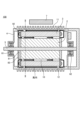
- FIG. 1 is a first cross-sectional view of the rotating electric machine 100 according to the first embodiment.
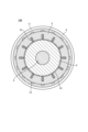
- FIG. 2 is a second cross-sectional view of the rotating electric machine 100 according to the first embodiment.
- FIG. 2 shows a main part in the II-II plane of FIG. 1.
- FIG. 1 and FIG. 2 show a schematic cross-section of the rotating electric machine 100.
- the rotating electric machine 100 has a rotor 2, a stator 3, a frame 4, and a cooling fan 7.
- the rotor 2 is disposed inside the frame 4 and rotates.
- the stator 3 is disposed inside the frame 4.
- the rotor 2 is surrounded by the stator 3.
- the cooling fan 7 is disposed outside the frame 4.
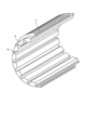
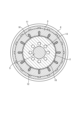
- FIG. 3 is a perspective view showing a main part of the frame 4 of the rotating electric machine 100 according to the first embodiment.
- FIG. 3 shows a schematic view of a main part of the frame 4.
- the rotor 2 has a shaft 5 that serves as the axis of rotation, and an end plate 81 that adjusts the rotational balance of the rotor 2.
- the shaft 5 is disposed so as to pass through the rotor 2, and is rotatably supported by a load side bearing 61 disposed on the load side of the frame 4, and an anti-load side bearing 62 disposed on the anti-load side.
- the direction in which the shaft 5 extends is also referred to as the axial direction.
- the stator 3 is cylindrical and has a coil 91 inside. A portion of the coil 91 protrudes outside the stator 3 as a coil end 92.
- the stator 3 is disposed so as to surround the rotor 2, and an air gap 10 exists between the stator 3 and the rotor 2.
- the central axis of the stator 3 is the same as the rotation axis of the rotor 2.
- the frame 4 is cylindrical, and the stator 3 is disposed inside the frame 4. Between the frame 4 and the stator 3, an internal air circulation flow path 12 is provided for circulating air inside the frame 4 in the axial direction.
- the axial direction is the direction in which the shaft 5 extends. More specifically, the axial direction is the direction of the rotation axis of the rotor 2.
- an external fin 11 is provided that is configured to be integrated with the frame 4. As shown in FIG. 1, a plurality of external fins 11 are disposed at intervals from each other in the axial direction. As shown in FIG. 2, for example, the external fin 11 is provided so as to go around the outer periphery of the cylindrical frame 4.
- FIG. 3 also shows the internal air circulation flow path 12 and the external fin 11.
- the cooling fan 7 is installed outside the frame 4 to send air to the outer fins 11. More specifically, the cooling fan 7 is installed outside the frame 4 at a position facing the circumferential side of the frame 4. The air blown out from the cooling fan 7 flows in the circumferential direction of the frame 4 through a flow path formed by the outer fins 11 provided on the outer peripheral surface of the frame 4. As a result, the air blown out from the cooling fan 7 dissipates the heat transferred to the frame 4 to the outside of the frame 4.
- the air flow path formed by the multiple outer fins 11 intersects with the internal air circulation flow path 12, preferably at right angles.
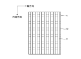
- Figure 4 is a diagram showing a state in which the internal air circulation flow path 12 and the multiple outer fins 11 are perpendicular to each other in the first embodiment.
- Figure 5 is a diagram showing a state in which the multiple outer fins 11 are inclined with respect to the internal air circulation flow path 12 in the first embodiment.
- the end plate 81 is disposed so that it penetrates the shaft 5, and rotates in accordance with the rotation of the rotor 2.
- the rotor 2 further has inner fins 82 provided on the end plate 81.
- the inner fins 82 are components that circulate the air inside the frame 4. When the end plate 81 rotates, the inner fins 82 also rotate, and the inner fins 82 agitate the air inside the frame 4. In FIG. 1, the direction of the agitated air is indicated by an arrow.
- the air inside the frame 4 is prevented from intermingling with the air blown out from the cooling fan 7 by the frame 4.
- the rotating electric machine 100 When the rotating electric machine 100 is operated, the rotor 2 rotates to operate a device installed on the load side at a desired rotational speed. This device is not shown.
- the cooling fan 7 installed on the outside of the frame 4 operates, and air flows in the circumferential direction of the frame 4 to cool the frame 4. As the air flows in the circumferential direction of the frame 4, heat generated by the rotating electric machine 100 dissipates, and the rotating electric machine 100 is cooled.
- the end plate 81 rotates in accordance with the rotation of the rotor 2, and the rotation of the end plate 81 rotates the inner fin 82, which then agitates the air inside the frame 4.
- the air agitated by the inner fin 82 flows through the air gap 10, and heat is transferred to the agitated air from the rotor 2 and the stator 3.
- the agitated air flows through the internal air circulation flow path 12 provided between the stator 3 and the frame 4, and heat is transferred to the agitated air from the stator 3 and the coil end 92.
- the rotating electric machine 100 can transfer the heat of the air whose temperature has increased inside the frame 4 to the frame 4.
- the heat transferred to the frame 4 is cooled by the cooling fan 7 and the outer fins 11. That is, the cooling fan 7 and the outer fins 11 cool the stator 3 and the air flowing through the internal air circulation flow path 12.
- the rotating electric machine 100 can cool the rotor 2 that is not in contact with the frame 4.
- the rotating electric machine 100 can prevent electrical malfunctions and deterioration caused by the rotor 2 becoming too hot.
- the inner fins 82 provided on the end plate 81 that rotates together with the rotor 2 stir the air inside the frame 4, and the stirred air circulates through the air gap 10 and the internal air circulation flow path 12, so that the rotating electric machine 100 transfers the heat of the rotor 2 to the outer fins 11 provided on the frame 4 via the frame 4, and dissipates it to the outside air by the cooling fan 7.
- the rotor 2 can be cooled without installing the cooling fan 7 in the axial direction, and therefore the axial size is suppressed.
- the rotor 2 may be provided with an internal rotor ventilation passage 13 that penetrates in the axial direction. This allows the air inside the frame 4 to circulate inside the rotor 2 as well, so that the rotor 2 can be cooled effectively.
- FIG. 6 is a schematic diagram showing a configuration in which the rotor 2 is provided with an internal rotor ventilation passage 13 that penetrates in the axial direction in the first embodiment.
- the number of internal air circulation passages 12 is 16, but the number of internal air circulation passages 12 can be any number.
- the number of internal rotor ventilation passages 13 is 8, but the number of internal rotor ventilation passages 13 can be any number.
- Embodiment 2 In the following embodiments, the same reference numerals as those in FIGS. 1 to 6 denote the same or similar components, and detailed description of the same or similar components will be omitted.
- FIG. 7 is a perspective view showing a main part of the frame 4 of the rotating electric machine 200 according to the second embodiment.
- FIG. 7 shows a schematic of the main part of the frame 4.
- the outer fins 11 are formed with circular ventilation holes 14 in the axial direction so that air can flow in the axial direction.
- the ventilation holes 14 are shown enlarged.
- the axial direction is the direction of the rotation axis of the rotor 2.
- the configuration of the rotating electric machine 200 other than the outer fins 11 is the same as that of the first embodiment.
- the outer fins 11 are formed with ventilation holes 14, the air blown out from the cooling fan 7 flows around the entire outer periphery of the frame 4, in comparison with the first embodiment. This allows the rotating electric machine 200 to efficiently transfer heat from the frame 4 to the outside air.
- the rotating electric machine 200 can efficiently transfer heat transferred to the frame 4 from the high-temperature air flowing through the internal air circulation flow path 12 to the air outside the frame 4. Therefore, the rotating electric machine 200 can suppress the rotor 2 from becoming too hot.
- the outer fin 11 has a circular ventilation hole 14, but the shape of the ventilation hole 14 is not limited to a circular shape.
- a rectangular ventilation hole 14a may be formed at the base portion of the outer fin 11.
- FIG. 8 is a perspective view showing a first modified example of a main portion of the frame 4 of the rotating electric machine 200 according to the second embodiment.
- FIG. 8 shows a schematic diagram of the first modified example of the main portion of the frame 4.
- the ventilation hole 14a is shown enlarged.
- the base portion is the portion where the outer fin 11 contacts the outer peripheral surface of the frame 4.
- FIG. 9 is a perspective view showing a second modification of the main part of the frame 4 of the rotating electric machine 200 according to the second embodiment.
- FIG. 9 shows a schematic diagram of the second modification of the main part of the frame 4.
- the rotating electric machine 300 according to the third embodiment has all of the components included in the rotating electric machine 100 according to the first embodiment.
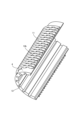
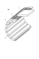
- Fig. 10 is a perspective view showing the appearance of the rotating electric machine 300 according to the third embodiment.
- Fig. 10 shows a schematic view of the appearance of the rotating electric machine 300.
- the rotating electric machine 300 further has a flow path cover 15 provided on the outside of the frame 4.
- the flow path cover 15 covers the outer fins 11. More specifically, the flow path cover 15 covers the tip portion of the outer fins 11. The tip portion of the outer fins 11 is the portion opposite the portion of the outer fins 11 that contacts the frame 4. The flow path cover 15 covers the outer fins 11 except for the portion facing the cooling fan 7 of the frame 4, and is formed so that the air blown out from the cooling fan 7 flows in the entire circumferential direction on the outside of the frame 4.
- the configuration of the rotating electric machine 300 other than the flow path cover 15 is the same as the configuration of embodiment 1.
- the rotating electric machine 300 has a flow path cover 15 that allows the air blown out from the cooling fan 7 to flow around the entire circumference of the frame 4, so the frame 4 can be cooled efficiently.
- the temperature difference that occurs around the circumference of the stator 3 can be reduced, making it possible to suppress the need to increase the size or add additional cooling fans 7 due to insufficient cooling capacity, and to prevent the rotating electric machine 300 from becoming larger.
- the outer fin 11 of embodiment 3 may have the ventilation holes 14, 14a, or 14b of embodiment 2 formed therein.
- the rotating electric machine 400 according to the fourth embodiment has all the components of the rotating electric machine 100 according to the first embodiment.
- FIG. 11 is a perspective view showing the appearance of the rotating electric machine 400 according to the fourth embodiment.
- FIG. 11 shows a schematic view of the appearance of the rotating electric machine 400.
- the outer fins 11 are provided on the outer peripheral surface of the frame 4 so that the heat transfer area increases as the air blown out from the cooling fan 7 moves downstream.
- the outer fins 11 are configured so that the heat transfer area is small in the vicinity of the cooling fan 7, and the heat transfer area increases as the air blown out from the cooling fan 7 flows downstream.
- the configuration of the rotating electric machine 400 other than the outer fins 11 is the same as the configuration of the first embodiment.
- the air blown out from the cooling fan 7 has a high heat dissipation capacity due to the turbulence of the air flow near the outlet of the cooling fan 7, but as it flows between the outer fins 11 attached to the outer peripheral surface of the frame 4, the flow is straightened and the heat dissipation capacity of the air blown out from the cooling fan 7 decreases. For this reason, by making the heat transfer area of the outer fins 11 small near the outlet of the cooling fan 7 and increasing the heat transfer area downstream, it is possible to achieve a uniform cooling effect in the circumferential direction.
- the rotating electric machine 400 has outer fins 11 provided on the outer periphery of the frame 4 so that the heat transfer area increases as the air blown out from the cooling fan 7 moves downstream.
- the outer fins 11 allow the rotating electric machine 400 to be cooled efficiently, and in turn, the temperature of the stator 3 can be made uniform, making it possible to prevent electrical malfunctions and deterioration of the stator 3 caused by the occurrence of localized high temperature spots.
- one way to increase the heat transfer area of the outer fins 11 provided on the outer peripheral surface of the frame 4 is to increase the height of the outer fins 11.
- the height of the outer fins 11 located relatively close to the cooling fan 7 is made lower than the height of the outer fins 11 located relatively far from the cooling fan 7.
- Another way to increase the heat transfer area of the outer fins 11 provided on the outer peripheral surface of the frame 4 is to increase the axial thickness of the outer fins 11.
- an outer fin 11 may be additionally installed in the axial direction downstream of the air blown out from the cooling fan 7.
- outer fin 11 of embodiment 4 may be formed with the ventilation holes 14, 14a, or 14b of embodiment 2.
- FIG. 12 is a cross-sectional view of a rotating electric machine 500 according to the fifth embodiment.
- Fig. 12 shows a schematic cross-section of the rotating electric machine 500.
- the rotating electric machine 500 has all the components of the rotating electric machine 100 according to the first embodiment.
- the rotating electric machine 500 further has a second cooling fan 7a disposed outside the frame 4. That is, the rotating electric machine 500 has two cooling fans.
- the second cooling fan 7a faces the cooling fan 7 across the frame 4.
- the configuration of the rotating electric machine 500 other than the second cooling fan 7a is the same as the configuration of the first embodiment.
- the air blown out from the cooling fan 7 flows in the circumferential direction of the frame 4, and the air blown out from the second cooling fan 7a also flows in the circumferential direction of the frame 4.
- the cooling fan 7 and the second cooling fan 7a are positioned opposite each other, the air blown out from the cooling fan 7 and the air blown out from the second cooling fan 7a can flow in the circumferential direction of the frame 4 without interfering with each other. Therefore, the volume of air blown out from one cooling fan can be reduced by more than half.
- the arrows show the direction in which the air blown out from the cooling fan 7 and the air blown out from the second cooling fan 7a flow.
- the rotating electric machine 500 can reduce the amount of heat dissipated by one cooling fan, making it possible to miniaturize the cooling fan 7 and the second cooling fan 7a. Therefore, since the amount of air blown out from each of the cooling fan 7 and the second cooling fan 7a can be reduced, the rotating electric machine 500 can reduce the noise generated by the cooling fan 7 and the second cooling fan 7a.
Landscapes
- Engineering & Computer Science (AREA)
- Power Engineering (AREA)
- Motor Or Generator Cooling System (AREA)
- Motor Or Generator Frames (AREA)
Abstract
La présente invention porte sur une machine électrique tournante (100) comprenant : un châssis (4) ; un rotor (2) qui est positionné à l'intérieur du châssis (4) et tourne ; un stator (3) qui est positionné à l'intérieur du châssis (4) ; un ventilateur de refroidissement (7) qui est positionné à l'extérieur du châssis (4) ; et une pluralité d'ailettes extérieures (11) qui sont disposées sur une surface périphérique externe du châssis (4). Entre le châssis (4) et le stator (3) se trouve un trajet d'écoulement de circulation d'air intérieur (12) pour permettre à l'air à l'intérieur du châssis (4) de circuler dans la direction de l'axe de rotation du rotor (2). Un trajet d'écoulement d'air formé par la pluralité d'ailettes extérieures (11) coupe le trajet d'écoulement de circulation d'air intérieur (12). Le rotor (2) est entouré par le stator (3), et comporte un arbre (5) qui sert d'axe de rotation, une plaque d'extrémité (81) qui règle l'équilibre de rotation du rotor (2), et une ailette interne (82) qui est disposée sur la plaque d'extrémité (81) et amène l'air à l'intérieur du châssis (4) à circuler.
Priority Applications (2)
| Application Number | Priority Date | Filing Date | Title |
|---|---|---|---|
| PCT/JP2023/021195 WO2024252571A1 (fr) | 2023-06-07 | 2023-06-07 | Machine électrique tournante |
| JP2023572888A JP7450836B1 (ja) | 2023-06-07 | 2023-06-07 | 回転電機 |
Applications Claiming Priority (1)
| Application Number | Priority Date | Filing Date | Title |
|---|---|---|---|
| PCT/JP2023/021195 WO2024252571A1 (fr) | 2023-06-07 | 2023-06-07 | Machine électrique tournante |
Publications (1)
| Publication Number | Publication Date |
|---|---|
| WO2024252571A1 true WO2024252571A1 (fr) | 2024-12-12 |
Family
ID=90194691
Family Applications (1)
| Application Number | Title | Priority Date | Filing Date |
|---|---|---|---|
| PCT/JP2023/021195 Ceased WO2024252571A1 (fr) | 2023-06-07 | 2023-06-07 | Machine électrique tournante |
Country Status (2)
| Country | Link |
|---|---|
| JP (1) | JP7450836B1 (fr) |
| WO (1) | WO2024252571A1 (fr) |
Citations (5)
| Publication number | Priority date | Publication date | Assignee | Title |
|---|---|---|---|---|
| JPS52108513U (fr) * | 1976-02-16 | 1977-08-18 | ||
| JPS5644566U (fr) * | 1979-09-17 | 1981-04-22 | ||
| JPH0993865A (ja) * | 1995-09-29 | 1997-04-04 | Hitachi Ltd | 誘導電動機 |
| JP2000308309A (ja) * | 1999-04-15 | 2000-11-02 | Toshiba Corp | 回転電機 |
| JP2013126309A (ja) * | 2011-12-15 | 2013-06-24 | Hitachi Ltd | 回転電機及びそれを備えた鉄道車両並びに電動車両 |
-
2023
- 2023-06-07 WO PCT/JP2023/021195 patent/WO2024252571A1/fr not_active Ceased
- 2023-06-07 JP JP2023572888A patent/JP7450836B1/ja active Active
Patent Citations (5)
| Publication number | Priority date | Publication date | Assignee | Title |
|---|---|---|---|---|
| JPS52108513U (fr) * | 1976-02-16 | 1977-08-18 | ||
| JPS5644566U (fr) * | 1979-09-17 | 1981-04-22 | ||
| JPH0993865A (ja) * | 1995-09-29 | 1997-04-04 | Hitachi Ltd | 誘導電動機 |
| JP2000308309A (ja) * | 1999-04-15 | 2000-11-02 | Toshiba Corp | 回転電機 |
| JP2013126309A (ja) * | 2011-12-15 | 2013-06-24 | Hitachi Ltd | 回転電機及びそれを備えた鉄道車両並びに電動車両 |
Also Published As
| Publication number | Publication date |
|---|---|
| JP7450836B1 (ja) | 2024-03-15 |
| JPWO2024252571A1 (fr) | 2024-12-12 |
Similar Documents
| Publication | Publication Date | Title |
|---|---|---|
| KR100424046B1 (ko) | 완전-폐쇄형모터 | |
| US8226350B2 (en) | Fan apparatus | |
| JP7038074B2 (ja) | 回転電機およびロータシャフト | |
| JP2006174541A (ja) | 回転電機 | |
| JP7687472B2 (ja) | 流体機械 | |
| JP2014033584A (ja) | 回転電機の風冷構造 | |
| WO2019142777A1 (fr) | Élément de dissipation de chaleur et ensemble moteur | |
| CN119042235A (zh) | 轴向磁悬浮轴承、磁悬浮旋转机械 | |
| US12292057B2 (en) | Fluid machine | |
| JP2014158342A (ja) | 回転電機 | |
| WO2024252571A1 (fr) | Machine électrique tournante | |
| US10797565B2 (en) | Motor with inner fan | |
| JP5129993B2 (ja) | 回転電機 | |
| JPH0823661A (ja) | 全閉外扇形電動機の冷却構造 | |
| JP4423271B2 (ja) | 電動機 | |
| JP5508704B2 (ja) | 回転電機 | |
| JPH07245914A (ja) | 回転電機の冷却風通風装置 | |
| JP6775715B1 (ja) | ロータおよび回転電機 | |
| JP2021175320A (ja) | モータ及び回転流体機械 | |
| CN114123636A (zh) | 电机平衡板和电机 | |
| WO2025186961A1 (fr) | Machine électrique tournante | |
| JP7329721B1 (ja) | 回転電機 | |
| JP2012200067A (ja) | 回転電機 | |
| JPH1118367A (ja) | モータ | |
| JP2017214834A (ja) | モータ一体型流体機械 |
Legal Events
| Date | Code | Title | Description |
|---|---|---|---|
| WWE | Wipo information: entry into national phase |
Ref document number: 2023572888 Country of ref document: JP |
|
| 121 | Ep: the epo has been informed by wipo that ep was designated in this application |
Ref document number: 23940673 Country of ref document: EP Kind code of ref document: A1 |
|
| NENP | Non-entry into the national phase |
Ref country code: DE |