EP2606323B1 - Instrument spectroscopique - Google Patents
Instrument spectroscopique Download PDFInfo
- Publication number
- EP2606323B1 EP2606323B1 EP11755094.7A EP11755094A EP2606323B1 EP 2606323 B1 EP2606323 B1 EP 2606323B1 EP 11755094 A EP11755094 A EP 11755094A EP 2606323 B1 EP2606323 B1 EP 2606323B1
- Authority
- EP
- European Patent Office
- Prior art keywords
- compartment
- tube
- deformable container
- bag
- instrument according
- Prior art date
- Legal status (The legal status is an assumption and is not a legal conclusion. Google has not performed a legal analysis and makes no representation as to the accuracy of the status listed.)
- Not-in-force
Links
Images




Classifications
-
- G—PHYSICS
- G01—MEASURING; TESTING
- G01J—MEASUREMENT OF INTENSITY, VELOCITY, SPECTRAL CONTENT, POLARISATION, PHASE OR PULSE CHARACTERISTICS OF INFRARED, VISIBLE OR ULTRAVIOLET LIGHT; COLORIMETRY; RADIATION PYROMETRY
- G01J1/00—Photometry, e.g. photographic exposure meter
- G01J1/02—Details
- G01J1/0271—Housings; Attachments or accessories for photometers
-
- G—PHYSICS
- G01—MEASURING; TESTING
- G01J—MEASUREMENT OF INTENSITY, VELOCITY, SPECTRAL CONTENT, POLARISATION, PHASE OR PULSE CHARACTERISTICS OF INFRARED, VISIBLE OR ULTRAVIOLET LIGHT; COLORIMETRY; RADIATION PYROMETRY
- G01J1/00—Photometry, e.g. photographic exposure meter
- G01J1/02—Details
-
- G—PHYSICS
- G01—MEASURING; TESTING
- G01J—MEASUREMENT OF INTENSITY, VELOCITY, SPECTRAL CONTENT, POLARISATION, PHASE OR PULSE CHARACTERISTICS OF INFRARED, VISIBLE OR ULTRAVIOLET LIGHT; COLORIMETRY; RADIATION PYROMETRY
- G01J1/00—Photometry, e.g. photographic exposure meter
- G01J1/02—Details
- G01J1/0252—Constructional arrangements for compensating for fluctuations caused by, e.g. temperature, or using cooling or temperature stabilization of parts of the device; Controlling the atmosphere inside a photometer; Purge systems, cleaning devices
-
- G—PHYSICS
- G01—MEASURING; TESTING
- G01J—MEASUREMENT OF INTENSITY, VELOCITY, SPECTRAL CONTENT, POLARISATION, PHASE OR PULSE CHARACTERISTICS OF INFRARED, VISIBLE OR ULTRAVIOLET LIGHT; COLORIMETRY; RADIATION PYROMETRY
- G01J3/00—Spectrometry; Spectrophotometry; Monochromators; Measuring colours
- G01J3/02—Details
-
- G—PHYSICS
- G01—MEASURING; TESTING
- G01J—MEASUREMENT OF INTENSITY, VELOCITY, SPECTRAL CONTENT, POLARISATION, PHASE OR PULSE CHARACTERISTICS OF INFRARED, VISIBLE OR ULTRAVIOLET LIGHT; COLORIMETRY; RADIATION PYROMETRY
- G01J3/00—Spectrometry; Spectrophotometry; Monochromators; Measuring colours
- G01J3/02—Details
- G01J3/0291—Housings; Spectrometer accessories; Spatial arrangement of elements, e.g. folded path arrangements
-
- G—PHYSICS
- G01—MEASURING; TESTING
- G01J—MEASUREMENT OF INTENSITY, VELOCITY, SPECTRAL CONTENT, POLARISATION, PHASE OR PULSE CHARACTERISTICS OF INFRARED, VISIBLE OR ULTRAVIOLET LIGHT; COLORIMETRY; RADIATION PYROMETRY
- G01J3/00—Spectrometry; Spectrophotometry; Monochromators; Measuring colours
- G01J3/28—Investigating the spectrum
- G01J3/45—Interferometric spectrometry
- G01J3/453—Interferometric spectrometry by correlation of the amplitudes
-
- G—PHYSICS
- G01—MEASURING; TESTING
- G01N—INVESTIGATING OR ANALYSING MATERIALS BY DETERMINING THEIR CHEMICAL OR PHYSICAL PROPERTIES
- G01N21/00—Investigating or analysing materials by the use of optical means, i.e. using sub-millimetre waves, infrared, visible or ultraviolet light
- G01N21/17—Systems in which incident light is modified in accordance with the properties of the material investigated
- G01N21/25—Colour; Spectral properties, i.e. comparison of effect of material on the light at two or more different wavelengths or wavelength bands
- G01N21/31—Investigating relative effect of material at wavelengths characteristic of specific elements or molecules, e.g. atomic absorption spectrometry
- G01N21/35—Investigating relative effect of material at wavelengths characteristic of specific elements or molecules, e.g. atomic absorption spectrometry using infrared light
-
- G—PHYSICS
- G02—OPTICS
- G02B—OPTICAL ELEMENTS, SYSTEMS OR APPARATUS
- G02B27/00—Optical systems or apparatus not provided for by any of the groups G02B1/00 - G02B26/00, G02B30/00
- G02B27/0006—Optical systems or apparatus not provided for by any of the groups G02B1/00 - G02B26/00, G02B30/00 with means to keep optical surfaces clean, e.g. by preventing or removing dirt, stains, contamination, condensation
-
- G—PHYSICS
- G01—MEASURING; TESTING
- G01J—MEASUREMENT OF INTENSITY, VELOCITY, SPECTRAL CONTENT, POLARISATION, PHASE OR PULSE CHARACTERISTICS OF INFRARED, VISIBLE OR ULTRAVIOLET LIGHT; COLORIMETRY; RADIATION PYROMETRY
- G01J3/00—Spectrometry; Spectrophotometry; Monochromators; Measuring colours
- G01J3/02—Details
- G01J3/0286—Constructional arrangements for compensating for fluctuations caused by temperature, humidity or pressure, or using cooling or temperature stabilization of parts of the device; Controlling the atmosphere inside a spectrometer, e.g. vacuum
-
- G—PHYSICS
- G01—MEASURING; TESTING
- G01N—INVESTIGATING OR ANALYSING MATERIALS BY DETERMINING THEIR CHEMICAL OR PHYSICAL PROPERTIES
- G01N21/00—Investigating or analysing materials by the use of optical means, i.e. using sub-millimetre waves, infrared, visible or ultraviolet light
- G01N21/17—Systems in which incident light is modified in accordance with the properties of the material investigated
- G01N21/25—Colour; Spectral properties, i.e. comparison of effect of material on the light at two or more different wavelengths or wavelength bands
- G01N21/31—Investigating relative effect of material at wavelengths characteristic of specific elements or molecules, e.g. atomic absorption spectrometry
- G01N21/35—Investigating relative effect of material at wavelengths characteristic of specific elements or molecules, e.g. atomic absorption spectrometry using infrared light
- G01N2021/3595—Investigating relative effect of material at wavelengths characteristic of specific elements or molecules, e.g. atomic absorption spectrometry using infrared light using FTIR
Definitions
- This invention relates to spectroscopic instruments, for example Fourier transform infrared (FTIR) spectrometers.
- FTIR Fourier transform infrared
- This invention relates to spectroscopic instruments having performance which is sensitive to humidity levels and/or the presence of other possible contaminants.
- Spectroscopic instruments can include components that are sensitive to moisture or other contaminants. These components might operate effectively only at humidity levels below some threshold humidity level, or tend to be damaged by moisture or other contaminants. For such instruments it is often impractical (for example too expensive) to provide a high vacuum enclosure, a dry gas purge system and/or a hermetically sealed enclosure for the components. Thus, some ingress of water and/or other contaminants is generally accepted. In such instruments, it is common to provide a compartment within which the components are placed together with desiccant to protect the components. Seals generally exist between the interior of the compartment and the surroundings, which reduce but do not prevent the flow of air, and hence water and other possible contaminants, into and out of the compartment.
- the desiccant When air containing moisture and other possible contaminants enters the compartment, some of the water content will be absorbed by the desiccant.
- the desiccant can also absorb some other possible contaminants, for example carbon dioxide.
- the desiccant can quickly become exhausted and need to be replaced to maintain the performance of the instrument. In some cases, the desiccant may need to be replaced as often as every three months. This adds to the maintenance operations required to keep the instrument working properly, and increases the amount, and therefore the cost, of the desiccant needed and/or increases the risk that the instrument will be used when not functioning to its maximum potential.
- EP 1 265 325 describes an optical device with a temperature sensitive etalon. This is housed in a housing which can be provided with a flexible outer wall part to compensate for increase in gas pressure caused by an increase in temperature.
- GB 644,217 discloses an apparatus for controlling moisture and pressure in a chamber for micro-wave testing equipment.
- the device comprises an air-bag located outside the actual measuring cavity wherin the air-bag is connected to the cavity with a vent which is filled with desiccant.
- a spectroscopic instrument comprising a compartment housing instrument components and desiccant to protect the instrument components, and a deformable container having at least one wall portion which is movable within the compartment so as to vary the volume of the compartment that is occupied by the deformable container as the container is deformed, the interior of the deformable container being in fluid communication with the surroundings of the instrument, such that a difference in pressure between the compartment and the surroundings tends to cause the deformable container to deform, moving the wall portion, the instrument further comprising a tube-like portion which is arranged to allow fluid communication between the interior of the deformable container and the surroundings.
- the volume of the compartment that is occupied by the deformable container can change so as to tend to equalise pressure between the compartment and the surroundings. This in turn can reduce any pumping effect, which might otherwise cause the exchange of air between the compartment and the surroundings. This can extend desiccant lifetime.
- the deformable container occupies between 5% and 50% of the volume of the compartment.
- the deformable container occupies between 10% and 15% of the volume of the compartment.
- At least part of the deformable container may be of flexible material.
- the movable wall of the deformable container may be of flexible material.
- At least part of the deformable container may be of heat sealable material.
- the deformable container may be of material with a low water diffusion rate, i.e. less than 30 mg water per square metre per day.
- the deformable container is of material which is moisture resistant.
- moisture resistant is used in the sense of resisting the transmission of moisture through the material.
- the deformable container may be of a laminate material.
- the laminate material may comprise at least one plastic layer and may comprise at least one metallic film layer.
- the laminate material is a metallic film coated plastics material.
- the deformable container may be a bag.
- the bag may comprise two or more walls which are heat sealed together.
- the spectroscopic instrument may comprise at least one valve for allowing fluid communication between the compartment and the surroundings, when a pressure difference between the compartment and the surroundings exceeds a predetermined threshold.
- the valve may allow such fluid communication when the pressure in the compartment exceeds that of the surroundings by a greater than a threshold amount and/or the valve may allow such fluid communication when the pressure in the surroundings exceeds that of in the compartment by a greater than a threshold amount.
- Two valves may be provided, one being an over-pressure valve for relieving over pressure in the compartment and one being an under-pressure valve for relieving under pressure in the compartment.
- the compartment may be defined by at least two housing parts with at least one seal therebetween.
- the at least one seal has a low water diffusivity, i.e. of approximately 100 g water per year or less. Preferably the at least one seal has a water diffusivity of less than 15 g water per year.
- the at least one seal may be of elastomer.
- the at least one seal may be of a fluoroelastomer, such as Viton, Fluorel or Aflas.
- the at least one seal may be of perfluoroelastomer. Where there are a plurality of seals, these may be of different materials.
- the tube-like portion may have a first portion which extends into the interior of the deformable container and may have a second portion which extends to or into the exterior of the compartment.
- a wall of the deformable container may comprise an aperture through which the tube-like portion extends.
- the tube-like portion may be mounted on the deformable container.
- Sealing means may be provided between the tube-like portion and the material of the deformable container to seal against ingress or egress of fluid through the aperture other than through the tube-like portion.
- the tube-like portion may comprise a first threaded portion which protrudes into the interior of the deformable container and receives a corresponding nut for mounting the tube-like portion to the deformable container.
- a first seal which may comprise an O ring may be provided between the tube-like portion and the material of the deformable container.
- a wall of the compartment may comprise an aperture through which the tube-like portion extends.
- the tube-like portion may be mounted to the compartment.
- the tube-like portion may protrude exterior to the compartment.
- the tube-like portion may comprise a (second) threaded portion which protrudes to or into the exterior to the compartment through the aperture in the wall of the compartment, and receives a corresponding nut for mounting the tube-like portion to the compartment.
- Sealing means may be provided between the tube-like portion and the compartment wall to seal against ingress or egress of fluid through the aperture in the compartment wall other than through the tube-like portion.
- a (second) seal which may comprise an O ring may be provided between the tube-like portion and the wall of the compartment.
- the O ring of at least one of the first and second seal may be of elastomer.
- the or each O ring may be one of a fluoroelastomer, such as Viton, Fluorel or Aflas, and a perfluoroelastomer.
- FIGs 1 and 2 schematically show part of a desk top Fourier transform infrared (FTIR) spectrometer which comprises a housing 1 made up of a base 11 and a cover 12. More detail of the cover 12 can be seen from the underside in Figure 3 .
- FTIR Fourier transform infrared
- a compartment 2 is defined within the housing 1 which in general terms is sealed from the exterior, ie the surroundings of the spectrometer.
- An O ring seal 13 (see Figures 2 and 6 ) is provided between the base 11 and cover 12 to seal the compartment 2 against the surroundings.
- the seal will not be perfect and in reality some air will tend to leak past or through the seal 13 into the compartment from time to time.
- the components of a spectrometer will tend to be sensitive to moisture and/or other contaminants.
- the present spectrometer is no exception, and for example in this embodiment, the components 3 include potassium bromide windows which can be damaged by humidity above a threshold level of say 40%.
- the presence of contaminant gases in the compartment 2 can have an adverse effect on the performance of the instrument.
- the compartment 2 houses desiccant 4 in an appropriate holder (again shown only in highly schematic form and only in Figure 2 of the drawings), which can help to protect the components 3.
- the compartment 2 also houses an air bag 5 (visible in situ in Figures 2 and 3 ).
- the bag 5 is mounted to the housing 1 and more particularly the cover 12 via a tube-like portion 6.
- One end of the tube-like portion 6 can be seen from the exterior of the spectrometer in Figure 1 and can be seen again in Figure 2 where the wall of the cover 12 has been cut away.
- Figure 4 shows the bag 5 with the tube-like portion 6 mounted to it in isolation from the remainder of the spectrometer 1.
- a bore runs through the tube-like portion 6 and this provides a fluid communication path between the interior of the bag 5 and the exterior of the compartment 2 (and hence the exterior of the spectrometer as a whole), when the bag 5 is mounted in the spectrometer via the tube-like portion 6 as illustrated in Figures 1 and 2 .
- the bag 5 is provided in the compartment 2 to help prevent the pumping effect described in the introduction above which can occur if there are pressure differences between the internal compartment 2 of the spectrometer and the surroundings. As discussed above, in such a circumstance, normally air will be driven out of or into the compartment 2 and this air will tend to carry moisture and/or other contaminants. As mentioned above, desiccant 4 is provided within the compartment 2 and this can help ensure proper operation of the spectrometer and can provide protection for the components 3 from moisture and/or other contaminants by virtue of absorbing these. However, the desiccant has only a finite capacity for absorbing moisture and/or other components, and thus has a finite life.
- the desiccant 4 In general terms, once the desiccant 4 is exhausted, it either needs to be replaced or the spectrometer will begin to operate at below optimum performance and may be damaged permanently.
- the bag 5 provided within the compartment 2 serves to extend the lifetime of the desiccant 4 by reducing the amount of air which tends to flow into and out of the compartment. Because the interior of the bag 5 is connected to the exterior via the tube-like portion 6, where there is a pressure difference between the interior of the compartment 2 and the surroundings, air will tend to be preferentially sucked into or driven out of the bag 5 rather than into and out of the remainder of the compartment 2 (through the O ring seal 13). This simple mechanism can dramatically improve the lifetime of the desiccant 4.
- the bag 5 is made from a flexible laminate material. In the present embodiment, it is important that the material of the bag 5 is both flexible to allow expansion and contraction of the bag 5 and also that it has a very low water permeability to ensure that moisture driven into and out of the bag is not allowed through the material of the bag into the compartment 2.
- a suitable material for the bag can be sheet material used in protective packaging of, for example, food stuffs. Preferably the material is heat sealable since this allows the bag to be formed from one or more sheet of the material which is heat sealed around the open edges to form the closed bag.
- the material may include a plastic film together with an aluminium foil layer to give the desired resistance against the transmission of water through the material.
- One suitable laminate material comprises a PET film layer with an aluminium foil layer bonded to this and an HDPE layer bonded to the other side of the aluminium foil layer.
- Such a material layer is heat sealable at approximately 200°C and provides a water vapour permeability of less than 0.05gm/m 2 /24hrs.
- the bag 5 is provided in a folded configuration with two main pockets which can expand and contract in use. This is merely to enable the bag 5 to fit in the space available within the housing 1 of the equipment. In other embodiments any suitable shape of bag 5 may be used.
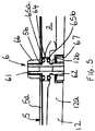
- the tube-like portion 6 is used to mount the bag 5 within the spectrometer. As can be most clearly seen in Figure 5 , the tube-like portion 6 is arranged so that material of a wall 5a of the bag 5 may be clamped to the tube-like portion 6 and further, the tube-like portion 6 can be clamped to the wall 12a of the housing 1, in this case the cover 12.
- a suitable aperture 5b is provided in the wall of the bag 5a through which a first threaded portion 62 of the tube-like portion projects.
- an appropriate aperture 12b is provided in the wall 12a of the cover 12 through which a second threaded portion 62 of the tube-like portion 6 projects.
- the tube-like portion 6 has a flange portion 64 which carries a first O ring 65a for contacting with and sealing against the wall 5a of the bag and a second O ring 65b for contacting with and sealing against the wall 12a of the cover 12.
- Corresponding nuts 66 and 67 are provided for the respective threaded portions 61 and 62, so that the wall of the bag 5a and the wall of the cover 12a can be clamped against the O rings 65a and 65b to provide an effective seal such that the ingress and egress of fluid through the apertures 5b and 12b in the bag 5 and cover 12 will only happen through the bore of the tube-like portion 6.
- the tube-like portion 6 conveniently provides a fluid communication path between the interior of the airbag 5 and the exterior of the compartment 2 (and hence the exterior of the spectrometer) as well as providing a mounting for the bag 5 within the spectrometer.
- the tube-like portion 6 will be mounted to the bag 5 during manufacture of the bag 5 and before at least the final seal is made to close the bag, thus providing a bag 5 plus tube-like portion 6 assembly as shown in Figure 4 which can then be mounted into the spectrometer.
- the bag 5 can protect the compartment 2 from most of the inflow and outflow of air which would normally occur.
- the change in volume which can be provided by the bag to counter differences in pressure will not be sufficient to neutralise the pressure difference between the compartment 2 and the surroundings. Therefore, as shown in Figure 7 , in order to protect the bag 5 and the seals 13, 65a, 65b from damage, the spectrometer is provided with an over pressure valve 7a and an under pressure valve 7b.
- Each of these valves is a one way pressure relief valve and is provided in an appropriate aperture in the wall 12a of the cover 12.
- the over pressure valve 7a is provided so that if the pressure within the compartment 2 is greater than the pressure of the surroundings by more than a threshold amount, then the over pressure valve 7a will open, allowing air to escape from the compartment 2. The opposite is true in respect of the under pressure valve 7b.
- both the over pressure valve 7a and under pressure valve 7b are in the form of umbrella valves.
- Each has a respective skirt 71a, 71b which seals against the wall 12a in normal circumstances, but which can be forced upwards by greater than a threshold pressure driven through the respective aperture in the wall portion 12a alongside the respective stem 72a, 72b into the void underneath the respective skirt 71a, 71b.
- a threshold pressure driven through the respective aperture in the wall portion 12a alongside the respective stem 72a, 72b into the void underneath the respective skirt 71a, 71b.
- seals 13, 65a, 65b use of fluroelastomers such as Viton, Fluorel or Aflas with a water diffusion rate of less than 100 grams of water per year is preferred. If a lower degree of protection against the ingress of water is required then other elastomers such as perfluroelastomer might be suitable.
- the bag 5 is provided wholly within the compartment 2 and particularly wholly within the housing 1 of the spectrometer. This helps to protect the bag 5 from damage whilst allowing it to perform its function of varying the volume of the remainder of the compartment 2 which is not occupied by the bag to allow pressure equalisation.
- the bag when the bag is expanded to its maximum extent by flow of air into its interior, it occupies in the order of 10% to 15% of the internal volume of the compartment.
- the bag may be chosen so that at its maximum extent it occupies a smaller or greater volume of the internal compartment than this.
- the spectrometer will be manufactured so that at a typical operating temperature and pressure, the bag will be midway through its inflation range. That is to say its volume will be at the mid-point such that there is a significant degree to which the volume of the bag may decrease as well as increase from the starting position.
- the material of the bag is chosen so as to be as flexible as is practical whilst providing the required barrier effect to gas and in particular moisture.
Landscapes
- Physics & Mathematics (AREA)
- Spectroscopy & Molecular Physics (AREA)
- General Physics & Mathematics (AREA)
- Electromagnetism (AREA)
- Optics & Photonics (AREA)
- Health & Medical Sciences (AREA)
- Chemical & Material Sciences (AREA)
- Analytical Chemistry (AREA)
- Biochemistry (AREA)
- General Health & Medical Sciences (AREA)
- Immunology (AREA)
- Pathology (AREA)
- Life Sciences & Earth Sciences (AREA)
- Sampling And Sample Adjustment (AREA)
- Spectrometry And Color Measurement (AREA)
- Packages (AREA)
Claims (12)
- Instrument spectroscopique comprenant un compartiment (2) logeant des composants d'instrument (3) et un absorbeur d'humidité (4) pour protéger les composants d'instrument, et un contenant déformable (5) ayant au moins une partie de paroi qui est mobile à l'intérieur du compartiment afin de modifier le volume du compartiment (2) qui est occupé par le contenant déformable (5) lorsque le contenant est déformé, l'intérieur du contenant déformable étant en communication de fluide avec les alentours de l'instrument, de sorte qu'une différence de pression entre le compartiment (2) et les alentours a tendance à provoquer la déformation du contenant déformable (5), déplaçant la partie de paroi, l'instrument comprenant en outre une partie en forme de tube (6) qui est agencée pour permettre la communication de fluide entre l'intérieur du contenant déformable (5) et les alentours.
- Instrument spectroscopique selon la revendication 1, qui comprend au moins une valve (7a, 7b) pour permettre la communication de fluide entre le compartiment et les alentours, lorsqu'une différence de pression entre le compartiment et les alentours dépasse un seuil prédéterminé.
- Instrument spectroscopique selon la revendication 2, dans lequel deux valves sont prévues, une étant une valve de surpression (7a) pour décharger la surpression dans le compartiment et une étant une valve de sous-pression (7b) pour décharger la sous-pression dans le compartiment.
- Instrument spectroscopique selon l'une quelconque des revendications précédentes, dans lequel le contenant déformable (5) est un matériau de stratifié, le matériau de stratifié comprenant au moins une couche en plastique et au moins une couche de film métallique.
- Instrument spectroscopique selon l'une quelconque des revendications précédentes, dans lequel le contenant déformable (5) comprend un sac (5).
- Instrument spectroscopique selon la revendication 5, dans lequel le sac (5) comprend deux parois ou plus qui sont thermosoudées ensemble.
- Instrument spectroscopique selon l'une quelconque des revendications précédentes, dans lequel la partie en forme de tube (6) est montée sur le contenant déformable (5) .
- Instrument spectroscopique selon l'une quelconque des revendications précédentes, dans lequel une paroi du contenant déformable comprend une ouverture (5b) à travers laquelle la partie en forme de tube (6) s'étend et des moyens de scellement (65a) sont prévus entre la partie en forme de tube (6) et le matériau du contenant déformable pour réaliser l'étanchéité contre l'entrée ou la sortie de fluide à travers l'ouverture différemment qu'à travers la partie en forme de tube.
- Instrument spectroscopique selon l'une quelconque des revendications précédentes, dans lequel la partie en forme de tube (6) est montée sur le compartiment.
- Instrument spectroscopique selon l'une quelconque des revendications précédentes, dans lequel une paroi du compartiment comprend une ouverture (12b) à travers laquelle la partie en forme de tube (6) s'étend, et des moyens d'étanchéité (65b) sont prévus entre la partie en forme de tube et la paroi de compartiment pour réaliser l'étanchéité contre l'entrée ou la sortie de fluide à travers l'ouverture dans la paroi de compartiment différemment qu'à travers la partie en forme de tube.
- Instrument spectroscopique selon l'une quelconque des revendications précédentes, dans lequel, lorsqu'il est à une étendue maximum, le contenant déformable (5) occupe entre 5% et 50% du volume du compartiment.
- Instrument spectroscopique selon l'une quelconque des revendications précédentes, dans lequel, lorsqu'il est à son étendue maximum, le contenant déformable (5) occupe entre 10% et 15% du volume du compartiment.
Applications Claiming Priority (2)
| Application Number | Priority Date | Filing Date | Title |
|---|---|---|---|
| GB1013917.8A GB2482904B (en) | 2010-08-19 | 2010-08-19 | Spectroscopic instruments |
| PCT/GB2011/001224 WO2012022936A1 (fr) | 2010-08-19 | 2011-08-16 | Instrument spectroscopique |
Publications (2)
| Publication Number | Publication Date |
|---|---|
| EP2606323A1 EP2606323A1 (fr) | 2013-06-26 |
| EP2606323B1 true EP2606323B1 (fr) | 2018-12-26 |
Family
ID=42984380
Family Applications (1)
| Application Number | Title | Priority Date | Filing Date |
|---|---|---|---|
| EP11755094.7A Not-in-force EP2606323B1 (fr) | 2010-08-19 | 2011-08-16 | Instrument spectroscopique |
Country Status (6)
| Country | Link |
|---|---|
| US (1) | US9322703B2 (fr) |
| EP (1) | EP2606323B1 (fr) |
| JP (1) | JP5787195B2 (fr) |
| CN (1) | CN103109166B (fr) |
| GB (1) | GB2482904B (fr) |
| WO (1) | WO2012022936A1 (fr) |
Citations (1)
| Publication number | Priority date | Publication date | Assignee | Title |
|---|---|---|---|---|
| GB644217A (en) * | 1947-04-09 | 1950-10-04 | Sperry Corp | Improvements in or relating to condensation control means |
Family Cites Families (28)
| Publication number | Priority date | Publication date | Assignee | Title |
|---|---|---|---|---|
| US3990429A (en) | 1975-02-18 | 1976-11-09 | Ppg Industries, Inc. | Solar heat collector having a breather tube |
| US3999536A (en) | 1975-03-19 | 1976-12-28 | Ppg Industries, Inc. | Solar energy absorber plate having a breather tube |
| CA1086145A (fr) | 1977-03-14 | 1980-09-23 | Ralph K. Day | Desembueur remplacable pour fenetre a double vitrage isolant, et construction de fenetre appropriee |
| US4342564A (en) * | 1979-06-15 | 1982-08-03 | Hans Lehmacher | Apparatus for the stacking and connection of synthetic-resin foil bags |
| US4542611A (en) | 1981-04-17 | 1985-09-24 | Day Ralph K | Double glass sheet insulating windows |
| US4560250A (en) | 1982-09-03 | 1985-12-24 | Russell Carl D | Explosion-proof and fog-free day and night outside rear view mirror incorporating variable position actuator |
| US4755031A (en) | 1987-07-20 | 1988-07-05 | Daviau Christopher A | Optical apparatus dehydrator |
| JPH069340Y2 (ja) * | 1989-01-31 | 1994-03-09 | 日本分光工業株式会社 | 光学機器用低湿度維持装置 |
| JPH10253454A (ja) * | 1997-03-14 | 1998-09-25 | Shimadzu Corp | フーリエ変換赤外分光光度計 |
| US6036321A (en) | 1997-05-16 | 2000-03-14 | Spectra Physics Lasers, Inc. | Crystal isolation housing |
| US5868667A (en) | 1998-03-27 | 1999-02-09 | Ethicon, Inc. | Pressure-equalizing cap |
| JP2002110275A (ja) | 2000-10-04 | 2002-04-12 | Yazaki Corp | 雄型端子 |
| GB2369070A (en) | 2000-11-18 | 2002-05-22 | Russell Smith Geoffrey | Regenerating desiccant humidity vent |
| DE10117170A1 (de) * | 2001-04-06 | 2002-10-10 | Zeiss Carl Jena Gmbh | Anordnung zum Druckausgleich für optische Geräte |
| EP1265325A1 (fr) * | 2001-06-08 | 2002-12-11 | Alcatel | Dispositif optique comportant un étalon termiquement stable |
| US6800114B2 (en) | 2002-08-07 | 2004-10-05 | Andrew Corporation | Pressure equalization apparatus and methods |
| JP3951870B2 (ja) * | 2002-09-19 | 2007-08-01 | 株式会社島津製作所 | 乾燥機付きフーリエ変換赤外分光光度計 |
| US6875486B2 (en) * | 2003-02-03 | 2005-04-05 | Drayton Miller | Package system and method |
| DE102004037638B4 (de) | 2004-08-02 | 2013-06-06 | Sew-Eurodrive Gmbh & Co. Kg | Anlage |
| CN101443971B (zh) * | 2004-11-23 | 2011-05-18 | 传感电子公司 | 压力平衡设备外罩 |
| JP3113903U (ja) | 2005-06-21 | 2005-09-22 | 株式会社島津製作所 | 赤外分光光度計 |
| JP2007108151A (ja) * | 2005-10-14 | 2007-04-26 | Junzo Umemura | 水蒸気や炭酸ガスによるスペクトル・ノイズのないフーリエ変換赤外分光光度計 |
| JP2007207641A (ja) * | 2006-02-03 | 2007-08-16 | Stanley Electric Co Ltd | 車両用灯具 |
| JP3126981U (ja) * | 2006-09-04 | 2006-11-16 | 株式会社島津製作所 | フーリエ変換赤外分光光度計 |
| JP2008085884A (ja) * | 2006-09-28 | 2008-04-10 | Fujifilm Corp | 沈胴式デジタルカメラ |
| EP2328821B1 (fr) * | 2008-08-01 | 2014-06-25 | Boehringer Ingelheim International GmbH | Unite de conditionnement avec un flacon en matiere plastique et un sac plastique place a l'interieur |
| JP5381845B2 (ja) | 2009-03-24 | 2014-01-08 | パナソニック株式会社 | 気体吸着デバイスの作製方法、気体吸着デバイス、および気体吸着デバイスの使用方法 |
| JP5236569B2 (ja) | 2009-04-28 | 2013-07-17 | 高知県 | 酸素酸イオン収着材の製造方法、酸素酸イオン収着材およびイオン収着処理方法 |
-
2010
- 2010-08-19 GB GB1013917.8A patent/GB2482904B/en not_active Expired - Fee Related
-
2011
- 2011-08-16 JP JP2013524478A patent/JP5787195B2/ja not_active Expired - Fee Related
- 2011-08-16 CN CN201180044991.8A patent/CN103109166B/zh not_active Expired - Fee Related
- 2011-08-16 EP EP11755094.7A patent/EP2606323B1/fr not_active Not-in-force
- 2011-08-16 WO PCT/GB2011/001224 patent/WO2012022936A1/fr not_active Ceased
- 2011-08-16 US US13/817,363 patent/US9322703B2/en active Active
Patent Citations (1)
| Publication number | Priority date | Publication date | Assignee | Title |
|---|---|---|---|---|
| GB644217A (en) * | 1947-04-09 | 1950-10-04 | Sperry Corp | Improvements in or relating to condensation control means |
Also Published As
| Publication number | Publication date |
|---|---|
| EP2606323A1 (fr) | 2013-06-26 |
| GB2482904A (en) | 2012-02-22 |
| CN103109166A (zh) | 2013-05-15 |
| US20130220014A1 (en) | 2013-08-29 |
| US9322703B2 (en) | 2016-04-26 |
| CN103109166B (zh) | 2016-08-17 |
| GB201013917D0 (en) | 2010-10-06 |
| WO2012022936A1 (fr) | 2012-02-23 |
| JP5787195B2 (ja) | 2015-09-30 |
| GB2482904B (en) | 2014-09-10 |
| JP2013534321A (ja) | 2013-09-02 |
Similar Documents
| Publication | Publication Date | Title |
|---|---|---|
| JP7474893B2 (ja) | リリーフ弁を備えたベント | |
| JP6636078B2 (ja) | ハウジング用の圧力補償装置 | |
| US20130323550A1 (en) | Battery pack pressure valve | |
| US10424770B2 (en) | Battery housing | |
| EP3306705B1 (fr) | Mécanisme de libération de pression | |
| US20160036025A1 (en) | Degassing valve | |
| US8870020B2 (en) | Closure device for a housing, sealed off from the environment, and a housing | |
| CN113195998B (zh) | 改进的热电池 | |
| KR101399411B1 (ko) | 포장용기의 가스 배출 장치 | |
| US20100084396A1 (en) | Airtight container | |
| EP1388362B1 (fr) | Procédés et dispositif d'équilibrage de pression | |
| US10443301B2 (en) | Thief hatches with diaphragm assisted sealing | |
| JP2012074553A (ja) | 油入電気機器用吸湿呼吸装置 | |
| US20050219740A1 (en) | Pressure control system for sealed enclosures | |
| JP2018086703A (ja) | ロボット | |
| EP2721324B1 (fr) | Isolateur de boîte à engrenages | |
| KR20080017051A (ko) | 저장 백을 배기하기 위한 방법 및 장치 | |
| US9322703B2 (en) | Spectroscopic instrument | |
| CN101233588B (zh) | 步进开关 | |
| US10065425B2 (en) | Printing fluid container | |
| ES2925849T3 (es) | Dispositivo de prueba de estanqueidad de sistemas para aislar dos medios de manera estanca | |
| WO2020085211A1 (fr) | Élément de ventilation | |
| JP4692929B2 (ja) | 負圧装置用開口部の密封装置及び方法 | |
| US20170085148A1 (en) | Motor, particularly for an automobile windscreen wiper mechanism | |
| US20220017281A1 (en) | Protective bag for shipping |
Legal Events
| Date | Code | Title | Description |
|---|---|---|---|
| PUAI | Public reference made under article 153(3) epc to a published international application that has entered the european phase |
Free format text: ORIGINAL CODE: 0009012 |
|
| 17P | Request for examination filed |
Effective date: 20130226 |
|
| AK | Designated contracting states |
Kind code of ref document: A1 Designated state(s): AL AT BE BG CH CY CZ DE DK EE ES FI FR GB GR HR HU IE IS IT LI LT LU LV MC MK MT NL NO PL PT RO RS SE SI SK SM TR |
|
| DAX | Request for extension of the european patent (deleted) | ||
| REG | Reference to a national code |
Ref country code: DE Ref legal event code: R079 Ref document number: 602011055148 Country of ref document: DE Free format text: PREVIOUS MAIN CLASS: G01J0001020000 Ipc: G01J0003020000 |
|
| RIC1 | Information provided on ipc code assigned before grant |
Ipc: G01J 1/02 20060101ALI20180518BHEP Ipc: G02B 27/00 20060101ALI20180518BHEP Ipc: G01J 3/02 20060101AFI20180518BHEP |
|
| GRAP | Despatch of communication of intention to grant a patent |
Free format text: ORIGINAL CODE: EPIDOSNIGR1 |
|
| STAA | Information on the status of an ep patent application or granted ep patent |
Free format text: STATUS: GRANT OF PATENT IS INTENDED |
|
| INTG | Intention to grant announced |
Effective date: 20180713 |
|
| GRAS | Grant fee paid |
Free format text: ORIGINAL CODE: EPIDOSNIGR3 |
|
| GRAA | (expected) grant |
Free format text: ORIGINAL CODE: 0009210 |
|
| STAA | Information on the status of an ep patent application or granted ep patent |
Free format text: STATUS: THE PATENT HAS BEEN GRANTED |
|
| RBV | Designated contracting states (corrected) |
Designated state(s): AL AT BE BG CH CY CZ DE DK EE ES FI FR GR HR HU IE IS IT LI LT LU LV MC MK MT NL NO PL PT RO RS SE SI SK SM TR |
|
| AK | Designated contracting states |
Kind code of ref document: B1 Designated state(s): AL AT BE BG CH CY CZ DE DK EE ES FI FR GR HR HU IE IS IT LI LT LU LV MC MK MT NL NO PL PT RO RS SE SI SK SM TR |
|
| REG | Reference to a national code |
Ref country code: CH Ref legal event code: EP |
|
| REG | Reference to a national code |
Ref country code: AT Ref legal event code: REF Ref document number: 1082046 Country of ref document: AT Kind code of ref document: T Effective date: 20190115 |
|
| REG | Reference to a national code |
Ref country code: DE Ref legal event code: R096 Ref document number: 602011055148 Country of ref document: DE |
|
| REG | Reference to a national code |
Ref country code: IE Ref legal event code: FG4D |
|
| REG | Reference to a national code |
Ref country code: NL Ref legal event code: FP |
|
| REG | Reference to a national code |
Ref country code: SE Ref legal event code: TRGR |
|
| PG25 | Lapsed in a contracting state [announced via postgrant information from national office to epo] |
Ref country code: NO Free format text: LAPSE BECAUSE OF FAILURE TO SUBMIT A TRANSLATION OF THE DESCRIPTION OR TO PAY THE FEE WITHIN THE PRESCRIBED TIME-LIMIT Effective date: 20190326 Ref country code: HR Free format text: LAPSE BECAUSE OF FAILURE TO SUBMIT A TRANSLATION OF THE DESCRIPTION OR TO PAY THE FEE WITHIN THE PRESCRIBED TIME-LIMIT Effective date: 20181226 Ref country code: LV Free format text: LAPSE BECAUSE OF FAILURE TO SUBMIT A TRANSLATION OF THE DESCRIPTION OR TO PAY THE FEE WITHIN THE PRESCRIBED TIME-LIMIT Effective date: 20181226 Ref country code: LT Free format text: LAPSE BECAUSE OF FAILURE TO SUBMIT A TRANSLATION OF THE DESCRIPTION OR TO PAY THE FEE WITHIN THE PRESCRIBED TIME-LIMIT Effective date: 20181226 Ref country code: FI Free format text: LAPSE BECAUSE OF FAILURE TO SUBMIT A TRANSLATION OF THE DESCRIPTION OR TO PAY THE FEE WITHIN THE PRESCRIBED TIME-LIMIT Effective date: 20181226 Ref country code: BG Free format text: LAPSE BECAUSE OF FAILURE TO SUBMIT A TRANSLATION OF THE DESCRIPTION OR TO PAY THE FEE WITHIN THE PRESCRIBED TIME-LIMIT Effective date: 20190326 |
|
| REG | Reference to a national code |
Ref country code: LT Ref legal event code: MG4D |
|
| PG25 | Lapsed in a contracting state [announced via postgrant information from national office to epo] |
Ref country code: AL Free format text: LAPSE BECAUSE OF FAILURE TO SUBMIT A TRANSLATION OF THE DESCRIPTION OR TO PAY THE FEE WITHIN THE PRESCRIBED TIME-LIMIT Effective date: 20181226 Ref country code: RS Free format text: LAPSE BECAUSE OF FAILURE TO SUBMIT A TRANSLATION OF THE DESCRIPTION OR TO PAY THE FEE WITHIN THE PRESCRIBED TIME-LIMIT Effective date: 20181226 Ref country code: GR Free format text: LAPSE BECAUSE OF FAILURE TO SUBMIT A TRANSLATION OF THE DESCRIPTION OR TO PAY THE FEE WITHIN THE PRESCRIBED TIME-LIMIT Effective date: 20190327 |
|
| REG | Reference to a national code |
Ref country code: AT Ref legal event code: MK05 Ref document number: 1082046 Country of ref document: AT Kind code of ref document: T Effective date: 20181226 |
|
| PG25 | Lapsed in a contracting state [announced via postgrant information from national office to epo] |
Ref country code: PL Free format text: LAPSE BECAUSE OF FAILURE TO SUBMIT A TRANSLATION OF THE DESCRIPTION OR TO PAY THE FEE WITHIN THE PRESCRIBED TIME-LIMIT Effective date: 20181226 Ref country code: ES Free format text: LAPSE BECAUSE OF FAILURE TO SUBMIT A TRANSLATION OF THE DESCRIPTION OR TO PAY THE FEE WITHIN THE PRESCRIBED TIME-LIMIT Effective date: 20181226 Ref country code: PT Free format text: LAPSE BECAUSE OF FAILURE TO SUBMIT A TRANSLATION OF THE DESCRIPTION OR TO PAY THE FEE WITHIN THE PRESCRIBED TIME-LIMIT Effective date: 20190426 Ref country code: CZ Free format text: LAPSE BECAUSE OF FAILURE TO SUBMIT A TRANSLATION OF THE DESCRIPTION OR TO PAY THE FEE WITHIN THE PRESCRIBED TIME-LIMIT Effective date: 20181226 |
|
| PG25 | Lapsed in a contracting state [announced via postgrant information from national office to epo] |
Ref country code: SM Free format text: LAPSE BECAUSE OF FAILURE TO SUBMIT A TRANSLATION OF THE DESCRIPTION OR TO PAY THE FEE WITHIN THE PRESCRIBED TIME-LIMIT Effective date: 20181226 Ref country code: EE Free format text: LAPSE BECAUSE OF FAILURE TO SUBMIT A TRANSLATION OF THE DESCRIPTION OR TO PAY THE FEE WITHIN THE PRESCRIBED TIME-LIMIT Effective date: 20181226 Ref country code: RO Free format text: LAPSE BECAUSE OF FAILURE TO SUBMIT A TRANSLATION OF THE DESCRIPTION OR TO PAY THE FEE WITHIN THE PRESCRIBED TIME-LIMIT Effective date: 20181226 Ref country code: IS Free format text: LAPSE BECAUSE OF FAILURE TO SUBMIT A TRANSLATION OF THE DESCRIPTION OR TO PAY THE FEE WITHIN THE PRESCRIBED TIME-LIMIT Effective date: 20190426 Ref country code: SK Free format text: LAPSE BECAUSE OF FAILURE TO SUBMIT A TRANSLATION OF THE DESCRIPTION OR TO PAY THE FEE WITHIN THE PRESCRIBED TIME-LIMIT Effective date: 20181226 |
|
| REG | Reference to a national code |
Ref country code: DE Ref legal event code: R097 Ref document number: 602011055148 Country of ref document: DE |
|
| PG25 | Lapsed in a contracting state [announced via postgrant information from national office to epo] |
Ref country code: DK Free format text: LAPSE BECAUSE OF FAILURE TO SUBMIT A TRANSLATION OF THE DESCRIPTION OR TO PAY THE FEE WITHIN THE PRESCRIBED TIME-LIMIT Effective date: 20181226 Ref country code: AT Free format text: LAPSE BECAUSE OF FAILURE TO SUBMIT A TRANSLATION OF THE DESCRIPTION OR TO PAY THE FEE WITHIN THE PRESCRIBED TIME-LIMIT Effective date: 20181226 |
|
| PLBE | No opposition filed within time limit |
Free format text: ORIGINAL CODE: 0009261 |
|
| STAA | Information on the status of an ep patent application or granted ep patent |
Free format text: STATUS: NO OPPOSITION FILED WITHIN TIME LIMIT |
|
| 26N | No opposition filed |
Effective date: 20190927 |
|
| PG25 | Lapsed in a contracting state [announced via postgrant information from national office to epo] |
Ref country code: SI Free format text: LAPSE BECAUSE OF FAILURE TO SUBMIT A TRANSLATION OF THE DESCRIPTION OR TO PAY THE FEE WITHIN THE PRESCRIBED TIME-LIMIT Effective date: 20181226 |
|
| PG25 | Lapsed in a contracting state [announced via postgrant information from national office to epo] |
Ref country code: TR Free format text: LAPSE BECAUSE OF FAILURE TO SUBMIT A TRANSLATION OF THE DESCRIPTION OR TO PAY THE FEE WITHIN THE PRESCRIBED TIME-LIMIT Effective date: 20181226 |
|
| PG25 | Lapsed in a contracting state [announced via postgrant information from national office to epo] |
Ref country code: LI Free format text: LAPSE BECAUSE OF NON-PAYMENT OF DUE FEES Effective date: 20190831 Ref country code: CH Free format text: LAPSE BECAUSE OF NON-PAYMENT OF DUE FEES Effective date: 20190831 Ref country code: LU Free format text: LAPSE BECAUSE OF NON-PAYMENT OF DUE FEES Effective date: 20190816 Ref country code: MC Free format text: LAPSE BECAUSE OF FAILURE TO SUBMIT A TRANSLATION OF THE DESCRIPTION OR TO PAY THE FEE WITHIN THE PRESCRIBED TIME-LIMIT Effective date: 20181226 |
|
| PG25 | Lapsed in a contracting state [announced via postgrant information from national office to epo] |
Ref country code: IE Free format text: LAPSE BECAUSE OF NON-PAYMENT OF DUE FEES Effective date: 20190816 |
|
| PG25 | Lapsed in a contracting state [announced via postgrant information from national office to epo] |
Ref country code: CY Free format text: LAPSE BECAUSE OF FAILURE TO SUBMIT A TRANSLATION OF THE DESCRIPTION OR TO PAY THE FEE WITHIN THE PRESCRIBED TIME-LIMIT Effective date: 20181226 |
|
| PG25 | Lapsed in a contracting state [announced via postgrant information from national office to epo] |
Ref country code: MT Free format text: LAPSE BECAUSE OF FAILURE TO SUBMIT A TRANSLATION OF THE DESCRIPTION OR TO PAY THE FEE WITHIN THE PRESCRIBED TIME-LIMIT Effective date: 20181226 Ref country code: HU Free format text: LAPSE BECAUSE OF FAILURE TO SUBMIT A TRANSLATION OF THE DESCRIPTION OR TO PAY THE FEE WITHIN THE PRESCRIBED TIME-LIMIT; INVALID AB INITIO Effective date: 20110816 |
|
| PG25 | Lapsed in a contracting state [announced via postgrant information from national office to epo] |
Ref country code: MK Free format text: LAPSE BECAUSE OF FAILURE TO SUBMIT A TRANSLATION OF THE DESCRIPTION OR TO PAY THE FEE WITHIN THE PRESCRIBED TIME-LIMIT Effective date: 20181226 |
|
| P01 | Opt-out of the competence of the unified patent court (upc) registered |
Effective date: 20230601 |
|
| PGFP | Annual fee paid to national office [announced via postgrant information from national office to epo] |
Ref country code: NL Payment date: 20230825 Year of fee payment: 13 |
|
| PGFP | Annual fee paid to national office [announced via postgrant information from national office to epo] |
Ref country code: IT Payment date: 20230822 Year of fee payment: 13 |
|
| PGFP | Annual fee paid to national office [announced via postgrant information from national office to epo] |
Ref country code: SE Payment date: 20230823 Year of fee payment: 13 Ref country code: FR Payment date: 20230824 Year of fee payment: 13 Ref country code: DE Payment date: 20230828 Year of fee payment: 13 Ref country code: BE Payment date: 20230825 Year of fee payment: 13 |
|
| REG | Reference to a national code |
Ref country code: DE Ref legal event code: R119 Ref document number: 602011055148 Country of ref document: DE |
|
| REG | Reference to a national code |
Ref country code: SE Ref legal event code: EUG |
|
| REG | Reference to a national code |
Ref country code: NL Ref legal event code: MM Effective date: 20240901 |
|
| PG25 | Lapsed in a contracting state [announced via postgrant information from national office to epo] |
Ref country code: NL Free format text: LAPSE BECAUSE OF NON-PAYMENT OF DUE FEES Effective date: 20240901 |
|
| REG | Reference to a national code |
Ref country code: BE Ref legal event code: MM Effective date: 20240831 |
|
| PG25 | Lapsed in a contracting state [announced via postgrant information from national office to epo] |
Ref country code: DE Free format text: LAPSE BECAUSE OF NON-PAYMENT OF DUE FEES Effective date: 20250301 |
|
| PG25 | Lapsed in a contracting state [announced via postgrant information from national office to epo] |
Ref country code: BE Free format text: LAPSE BECAUSE OF NON-PAYMENT OF DUE FEES Effective date: 20240831 Ref country code: IT Free format text: LAPSE BECAUSE OF NON-PAYMENT OF DUE FEES Effective date: 20240816 |
|
| PG25 | Lapsed in a contracting state [announced via postgrant information from national office to epo] |
Ref country code: FR Free format text: LAPSE BECAUSE OF NON-PAYMENT OF DUE FEES Effective date: 20240831 |
|
| PG25 | Lapsed in a contracting state [announced via postgrant information from national office to epo] |
Ref country code: SE Free format text: LAPSE BECAUSE OF NON-PAYMENT OF DUE FEES Effective date: 20240817 |