EP2606539B1 - Borne électrique femelle - Google Patents
Borne électrique femelle Download PDFInfo
- Publication number
- EP2606539B1 EP2606539B1 EP11781592.8A EP11781592A EP2606539B1 EP 2606539 B1 EP2606539 B1 EP 2606539B1 EP 11781592 A EP11781592 A EP 11781592A EP 2606539 B1 EP2606539 B1 EP 2606539B1
- Authority
- EP
- European Patent Office
- Prior art keywords
- terminal
- outer frame
- elastic
- top wall
- inner frame
- Prior art date
- Legal status (The legal status is an assumption and is not a legal conclusion. Google has not performed a legal analysis and makes no representation as to the accuracy of the status listed.)
- Not-in-force
Links
- 238000000034 method Methods 0.000 claims description 13
- 238000002788 crimping Methods 0.000 claims description 12
- 239000002184 metal Substances 0.000 claims description 10
- 229910052751 metal Inorganic materials 0.000 claims description 10
- 238000003780 insertion Methods 0.000 claims description 7
- 230000037431 insertion Effects 0.000 claims description 7
- 238000005304 joining Methods 0.000 claims description 7
- 230000001681 protective effect Effects 0.000 claims description 6
- 238000004519 manufacturing process Methods 0.000 claims description 4
- 230000002035 prolonged effect Effects 0.000 claims description 4
- 238000003466 welding Methods 0.000 claims description 3
- PCHJSUWPFVWCPO-UHFFFAOYSA-N gold Chemical compound [Au] PCHJSUWPFVWCPO-UHFFFAOYSA-N 0.000 claims description 2
- 239000010931 gold Substances 0.000 claims description 2
- 229910052737 gold Inorganic materials 0.000 claims description 2
- 230000000295 complement effect Effects 0.000 description 2
- 230000009286 beneficial effect Effects 0.000 description 1
- 230000001419 dependent effect Effects 0.000 description 1
- 230000005611 electricity Effects 0.000 description 1
- 230000014759 maintenance of location Effects 0.000 description 1
- 238000007747 plating Methods 0.000 description 1
- 238000004381 surface treatment Methods 0.000 description 1
Images



Classifications
-
- H—ELECTRICITY
- H01—ELECTRIC ELEMENTS
- H01R—ELECTRICALLY-CONDUCTIVE CONNECTIONS; STRUCTURAL ASSOCIATIONS OF A PLURALITY OF MUTUALLY-INSULATED ELECTRICAL CONNECTING ELEMENTS; COUPLING DEVICES; CURRENT COLLECTORS
- H01R13/00—Details of coupling devices of the kinds covered by groups H01R12/70 or H01R24/00 - H01R33/00
- H01R13/02—Contact members
- H01R13/10—Sockets for co-operation with pins or blades
- H01R13/11—Resilient sockets
- H01R13/113—Resilient sockets co-operating with pins or blades having a rectangular transverse section
-
- H—ELECTRICITY
- H01—ELECTRIC ELEMENTS
- H01R—ELECTRICALLY-CONDUCTIVE CONNECTIONS; STRUCTURAL ASSOCIATIONS OF A PLURALITY OF MUTUALLY-INSULATED ELECTRICAL CONNECTING ELEMENTS; COUPLING DEVICES; CURRENT COLLECTORS
- H01R43/00—Apparatus or processes specially adapted for manufacturing, assembling, maintaining, or repairing of line connectors or current collectors or for joining electric conductors
- H01R43/16—Apparatus or processes specially adapted for manufacturing, assembling, maintaining, or repairing of line connectors or current collectors or for joining electric conductors for manufacturing contact members, e.g. by punching and by bending
-
- Y—GENERAL TAGGING OF NEW TECHNOLOGICAL DEVELOPMENTS; GENERAL TAGGING OF CROSS-SECTIONAL TECHNOLOGIES SPANNING OVER SEVERAL SECTIONS OF THE IPC; TECHNICAL SUBJECTS COVERED BY FORMER USPC CROSS-REFERENCE ART COLLECTIONS [XRACs] AND DIGESTS
- Y10—TECHNICAL SUBJECTS COVERED BY FORMER USPC
- Y10T—TECHNICAL SUBJECTS COVERED BY FORMER US CLASSIFICATION
- Y10T29/00—Metal working
- Y10T29/49—Method of mechanical manufacture
- Y10T29/49002—Electrical device making
- Y10T29/49117—Conductor or circuit manufacturing
- Y10T29/49204—Contact or terminal manufacturing
Definitions
- the invention relates to electrical terminals.
- the present invention relates to a female electrical terminal having an outer frame and an elastic member.
- the outer frame is designed to receive the complementary male terminal.
- the elastic member applies a force on the male terminal inside the cavity, to retain the male terminal therein.
- the elastic member also ensures a good physical terminal between the two electrical terminals, and hence a correct conduction of electricity.
- An aim of the invention is to increase the retention force between the male and female terminals.
- the electrical terminal according to the invention is manufactured from a single metal sheet.
- the electrical terminal comprises a crimping portion and a contact portion adapted to mate with a corresponding male terminal to be inserted in the female terminal.
- the contact portion comprises an outer frame having a top wall, a bottom wall parallel and opposed to the top wall, and two side walls perpendicular to and joining the top and bottom walls.
- a first elastic contact member extends from the inner frame, and bears on an inner portion of the bottom wall.
- a second elastic contact member extends from the inner frame and bears on an inner portion of the top wall.
- first and second elastic contact members have a convex shape oriented toward one another. As a result they exert a clamping force greater than a predetermined value on the male terminal inserted in the female terminal.
- the elastic members have to slide respectively the top and bottom walls. This increases the strength of the elastic members on the male terminal compared to a configuration where the elastic members would have opposed only an elastic strength.
- Each of the elastic member has a tip as the end thereof. Further, the top, bottom and side walls are folded from a generally rectangular main portion of the metal sheet.
- Such a terminal is less expensive to manufacture since it is made out of a single metal sheet. Contrarily to the terminal described in WO2008/120048 in which the elastic member is made of a part separate from the outer frame.
- the invention is directed to a method to manufacture an electrical terminal as described above.
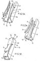
- FIG. 1 shows an electrical female terminal 100 according to an embodiment of the invention.
- the electrical female terminal comprises:
- the contact portion 101 comprises an outer frame 10 having a top wall 11, a bottom wall 12 parallel and opposed to the top wall, and two side walls 13,14 perpendicular to and joining the top and bottom walls.
- the top and bottom walls 11,12 are parallel to a terminal insertion plane P containing the longitudinal X axis and a transversal Y axis perpendicular to the longitudinal X axis.
- the outer frame 10 is obtained by folding a metal sheet, and it results from this process a joint or seam 30 joining edges 11a and 21a (visible on figure 3 ) respectively attached to the top wall 11 and a border 21 of the side wall 13. Both sides 11a,21a of the joint 30 may be welded together to reinforce the strength of the outer frame 10.
- the outer frame 10 may comprise a laser soldered seam 30.
- the contact portion 101 comprises an inner frame 15 encased in a rear portion 16 of the outer frame, the rear portion 16 being longitudinally opposed to the already mentioned front portion 17, the crimping portion 102 being attached to this rear portion 16 (the crimping portion 102 is not shown on figures 3 and 4 ).
- the inner frame 15 comprises:
- the first elastic contact member 1 comprises :
- the second elastic contact member 2 comprises:
- first elastic contact member 1 and second elastic contact member 2 are symmetrically disposed relative to the already mentioned terminal insertion plane P.
- top wall 11 is prolonged by a protecting rim 8 extending inwardly substantially perpendicularly to both the top wall 11 and the X axis and parallel to the transversal Y axis.
- the bottom wall 12 is prolonged by a protecting rim 9 extending inwardly substantially perpendicularly to both the bottom wall 12 and the X axis and parallel to the transversal Y axis.
- the protecting rims 8, 9 protect the contact portion of the electrical female terminal against mechanical damage upon insertion. It particularly prevents that the tips 1d, 2d respectively of the first and second elastic contact members 1,2 be damaged by the misalignment of the tip 150d of the male terminal 150 (see Fig. 3 ).
- the contact portion 101 comprises a locking lance 5 adapted to lock the terminal 100 in a plastic housing as known in the art.
- the locking lance 5 extends slantwise outwardly from the front area of the top wall 11 and exhibits a sufficient flexibility to be pushed inwardly when the terminal is inserted in a housing.
- the contact portion 101 also comprises a protective wall 6 adapted to protect the locking lance against mechanical damage, for example during the insertion of the terminal in the plastic housing or during handling of the terminal prior to insertion.
- This protective wall is also advantageously used as orientation means.
- the housing may be designed with a groove for accommodating the protective wall only when the terminal is properly oriented on the X axis, with regard to the housing.
- the protective wall extends outwardly away from the outer frame 10 and comprises a slanted edge 6a prolonged by a second edge 6b parallel to the X axis.
- the locking lance 5 comprises a curved side portion 26 adapted to come into contact with a stop portion 27 belonging to the side wall 14 (cf. Fig. 2 ). This arrangement prevents the locking lance 5 from undergoing an excessive distortion when pushed inwardly by an unlocking tool.
- the first and second elastic members 1,2 When no male terminal is inserted in the electrical female terminal, the first and second elastic members 1,2 are in their rest position and their contact areas 1e, 2e are separated by a distance E2 (see fig. 4 ).
- an electrical connection comprising a male terminal 150 having a thickness E1 and a female terminal 100 as described above.
- the thickness E1 of the male terminal is greater that the distance E2 separating first and second elastic members 1,2 in their rest positions.
- the first and second elastic members 1,2 exert a clamping force greater than 5 Newtons on the male terminal 150 inserted therein. Furthermore, this clamping force is symmetrically exerted on the male terminal which is beneficial for the mechanical balance of the electrical connection.
- the female terminal Before crimping a wire 103 on the female terminal, the female terminal is attached to a strip 80 as shown on Figures 2 , 6 and 7 .
- the band comprises a continuous strip 80 and a plurality of metallic blanks 50 each one of which being attached to the strip and adapted to be folded in order to form a female terminal 100 as described above.
- Such a band is obtained from stamping a metallic sheet.
- Each blank 50 comprises a first blank portion 51 corresponding to the contact portion 101 and a second blank portion 52 corresponding to the crimping portion 102.
- the first blank portion 51 corresponding to the contact portion is a stamped flat metal sheet extending in a plane comprising the longitudinal X axis and the transversal Y axis.
- the first blank portion 51 comprises:
- the third strip 15' is folded as a U-shape in such a way that the first strip 1' and second strip 2' faces each other and form the elastic members 1,2 and the inner frame 15 of the electrical terminal. Further the locking lance 5 is also formed at this step of the process.
- further processing comprises the forming of the border 21, the protecting rims 8,9 and partly forming the outer frame 10.
- the outer frame 10 is further folded.
- a further process may include the welding of such seam, for example by laser welding technique.
- the folding of the second blank portion 52 to result in the crimping portion 102 may be performed simultaneously.
- a band comprising a continuous strip 80 and a plurality of terminals 100 attached to the strip, as illustrated on Figure 7 .
- a breakable section 81 attaches each terminal 100 to the strip 80 and can be broken or cut out to give individual electrical terminals 100.
- the process may also include a surface treatment step, like for example a gold plating treatment that can be performed on the whole band with blanks or that can be performed locally on the elastic members 1,2, especially on the contact areas 1e, 2e.
- a surface treatment step like for example a gold plating treatment that can be performed on the whole band with blanks or that can be performed locally on the elastic members 1,2, especially on the contact areas 1e, 2e.
Landscapes
- Engineering & Computer Science (AREA)
- Manufacturing & Machinery (AREA)
- Manufacturing Of Electrical Connectors (AREA)
- Connections Effected By Soldering, Adhesion, Or Permanent Deformation (AREA)
Claims (13)
- Borne électrique femelle (100), fabriquée à partir d'une unique tôle métallique, comprenant une portion de sertissage (102) et une portion de contact (101) adaptée à s'accoupler avec un une borne mâle correspondante (150) à insérer dans celle-ci dans une portion antérieure (17) de la portion de contact, la portion de contact (101) comprenant :- un cadre extérieur (10) ayant une paroi supérieure (11), une paroi inférieure (12) parallèle et opposée à la paroi supérieure, et deux parois latérales (13, 14) perpendiculaires à et rejoignant les parois supérieure et inférieure,- un cadre intérieur (15) enchâssé dans une portion postérieure (16) du cadre extérieur,- un premier élément de contact élastique (1) s'étendant depuis le cadre intérieur (15), ayant une portion coulissante (1c) qui porte en coulissement sur une portion intérieure de la paroi inférieure, et ayant un embout (1d) à son extrémité,- un second élément de contact élastique (2) s'étendant depuis le cadre intérieur (15), ayant une portion coulissante (2c) qui porte en coulissement sur une portion intérieure de la paroi supérieure, et ayant un embout (2d) à son extrémité,
le premier et le second élément de contact élastique (1, 2) ayant une forme convexe orientée l'un vers l'autre,
caractérisé en ce que la paroi supérieure, la paroi inférieure et les parois latérales (11, 12, 13, 14) sont repliées depuis une portion principale généralement rectangulaire (10') de la tôle métallique. - Borne selon la revendication 1, dans laquelle le premier élément de contact élastique (1) et le second élément de contact élastique (2) sont agencés symétriquement par rapport à un plan d'insertion de borne (P) parallèle à la paroi supérieure.
- Borne selon la revendication 1 ou 2, dans laquelle chacun du premier et du second élément de contact élastique (1, 2) a respectivement une portion de base (1a, 2a) rigide avec le cadre intérieur (15), une portion incurvée (1b, 2b) et une portion coulissante (1c, 2c) qui porte en coulissement sur la portion intérieure respectivement de la paroi supérieure et de la paroi inférieure.
- Borne selon l'une quelconque des revendications précédentes, dans laquelle le cadre intérieur (15) a une section transversale en forme de U avec une portion intermédiaire (15a) et des portions terminales (15b, 15c), dans laquelle les éléments élastiques (1, 2) sont respectivement attachés à chacune des portions terminales.
- Borne selon l'une quelconque des revendications précédentes, dans laquelle chacune de la paroi supérieure de la paroi inférieure est respectivement prolongée par un rebord de protection (8, 9) s'étendant vers l'intérieur sensiblement perpendiculairement à la paroi supérieure (11) grâce à quoi le premier et le second élément de contact élastique (1, 2) sont protégés vis-à-vis d'un endommagement mécanique lors de l'insertion de la borne mâle correspondante (150).
- Borne selon l'une quelconque des revendications précédentes, comprenant une languette de blocage (5) adaptée à bloquer la borne dans un boîtier, et une paroi protectrice (6) adaptée à protéger la languette de blocage à l'encontre d'un endommagement mécanique.
- Borne selon l'une quelconque des revendications précédentes, dans laquelle les éléments élastiques sont localement plaqués à l'or.
- Borne selon l'une quelconque des revendications précédentes, dans laquelle le cadre extérieur (10) comprend un joint soudé au laser (30).
- Dispositif de connexion électrique comprenant une borne mâle (150) et une borne femelle (100) selon l'une quelconque des revendications précédentes, dans lequel le premier et le second élément élastique (1, 2) exercent une force de serrage plus forte que 5N sur la borne mâle (150) insérée dans ceux-ci.
- Bande comprenant un ruban continu (80) et une pluralité de bornes (100) selon l'une quelconque des revendications 1 à 8 attachées sur le ruban.
- Procédé pour fabriquer une borne électrique femelle (100) ayant une portion de sertissage (102) et portion de contact (101) adaptée à s'accoupler avec une borne mâle correspondante (150) à insérer dans celle-ci dans une portion antérieure (17) de la portion de contact, le procédé comprenant les étapes consistant à :- former un cadre extérieur (10) de la portion de contact avec une paroi supérieure (11), une paroi inférieure (12) parallèle et opposée à la paroi supérieure, et deux parois latérales (13, 14) perpendiculaires et rejoignant les parois supérieure et inférieure,- former un cadre intérieur (15) de la portion de contact enchâssé dans une portion postérieure (16) du cadre extérieur,- former un premier élément de contact élastique (1) de la portion de contact en s'étendant depuis le cadre intérieur (15), ayant une portion coulissante (1c) qui porte en coulissement sur une portion intérieure (12b) de la paroi inférieure, et ayant un embout (1d) à son extrémité,- former un second élément de contact élastique (2) de la portion de contact en s'étendant depuis le cadre intérieur (15), ayant une portion coulissante (2c) qui porte en coulissement sur une portion intérieure (11b) de la paroi supérieure, et ayant un embout (2d) à son extrémité,
le premier et le second élément de contact élastique ont une forme convexe, orientés l'un vers l'autre,
caractérisé en ce que la paroi supérieure, la paroi inférieure et les parois latérales (11, 12, 13, 14) sont repliées depuis une portion principale généralement rectangulaire (10') de la tôle métallique. - Procédé selon la revendication 11, le procédé comprenant les étapes consistant à :a) fournir une tôle métallique plane s'étendant dans un plan comprenant un axe longitudinal (X) et un plan transversal (Y), la tôle métallique plane comprenant une première portion d'ébauche (51) à replier pour donner la portion de contact (101) et une seconde portion d'ébauche (52) à replier pour donner la portion de sertissage (102), la première portion d'ébauche (51) comprenant :- un premier ruban (1') s'étendant le long de l'axe longitudinal (X), ayant une première portion de base (1'a),- un second ruban (2') s'étendant le long de l'axe longitudinal (X), ayant une seconde portion de base (2'a),- un troisième ruban (15') s'étendant le long de l'axe transversal Y et rejoignant la première portion de base (1'a) et la seconde portion de base (2'a),- une portion principale de forme généralement rectangulaire (10', 5', 6', 16', 8', 11'),b) replier le premier ruban, le second ruban et le troisième ruban (1', 2', 15') pour donner en résultat le premier et le second élément élastique (1, 2) et le cadre intérieur (15) de la borne électrique (100),c) replier la portion principale de forme généralement rectangulaire (10', 5', 6', 16', 8', 11') pour donner en résultat le cadre extérieur (10), etd) replier la seconde portion d'ébauche (52) pour donner en résultat la portion de sertissage (102).
- Procédé selon la revendication 12, comprenant l'étape additionnelle consistant à souder un joint (30) sur le cadre extérieur (10) pour donner en résultat un cadre extérieur fermé.
Applications Claiming Priority (2)
| Application Number | Priority Date | Filing Date | Title |
|---|---|---|---|
| IB2010002439 | 2010-08-17 | ||
| PCT/IB2011/002075 WO2012023037A1 (fr) | 2010-08-17 | 2011-08-05 | Borne électrique femelle |
Publications (2)
| Publication Number | Publication Date |
|---|---|
| EP2606539A1 EP2606539A1 (fr) | 2013-06-26 |
| EP2606539B1 true EP2606539B1 (fr) | 2016-10-12 |
Family
ID=44925576
Family Applications (1)
| Application Number | Title | Priority Date | Filing Date |
|---|---|---|---|
| EP11781592.8A Not-in-force EP2606539B1 (fr) | 2010-08-17 | 2011-08-05 | Borne électrique femelle |
Country Status (4)
| Country | Link |
|---|---|
| US (1) | US8944860B2 (fr) |
| EP (1) | EP2606539B1 (fr) |
| CN (1) | CN103109421B (fr) |
| WO (1) | WO2012023037A1 (fr) |
Families Citing this family (16)
| Publication number | Priority date | Publication date | Assignee | Title |
|---|---|---|---|---|
| WO2014127817A1 (fr) * | 2013-02-21 | 2014-08-28 | Delphi International Operations Luxembourg S.À.R.L. | Borne électrique avec lance de verrouillage |
| EP2797173B8 (fr) * | 2013-04-26 | 2019-01-09 | Aptiv Technologies Limited | Borne électrique pourvue d'une lance de verrouillage et son procédé de fabrication |
| US9300069B2 (en) | 2014-02-13 | 2016-03-29 | Delphi Technologies, Inc. | Electrical terminal with enhanced clamping force |
| CN107919553B (zh) * | 2016-10-11 | 2024-02-27 | 泰科电子(上海)有限公司 | 连接端子 |
| CN106384901B (zh) * | 2016-11-29 | 2018-09-04 | 河南天海电器有限公司 | 汽车用激光焊接端子 |
| DE102016125764A1 (de) | 2016-12-28 | 2018-06-28 | Lear Corporation | Zweistückige elektrische clean-body-anschlussbuchse |
| EP3451467B1 (fr) * | 2017-09-01 | 2022-02-23 | Tyco Electronics France SAS | Contact électrique d'une feuille de métal ayant une languette d'encliquetage et/ou une butée de fin de course allongée plastiquement et son procédé de fabrication |
| JP7107708B2 (ja) * | 2018-03-15 | 2022-07-27 | イリソ電子工業株式会社 | コネクタ |
| CN110098518B (zh) * | 2019-06-03 | 2024-01-30 | 厦门广泓工贸有限公司 | 一种稳定型母端子及其应用的稳定型公母对插电连接器 |
| JP7073429B2 (ja) * | 2020-03-18 | 2022-05-23 | 矢崎総業株式会社 | 端子付き電線の製造方法、及び、端子付き電線 |
| CN116325372A (zh) * | 2020-09-21 | 2023-06-23 | 莫列斯有限公司 | 抗磨端子配件 |
| US11387586B2 (en) * | 2020-11-09 | 2022-07-12 | Aptiv Technologies Limited | High voltage (HV) terminal frame and method of manufacturing the same |
| JP7398412B2 (ja) * | 2021-07-28 | 2023-12-14 | 矢崎総業株式会社 | 電気接続構造 |
| CN114465055A (zh) * | 2022-03-18 | 2022-05-10 | 安徽江淮汽车集团股份有限公司 | 一种汽车插座端子结构 |
| CN117855906B (zh) * | 2022-09-30 | 2025-04-08 | 比亚迪股份有限公司 | 端子、电连接器、线束和车辆 |
| USD1108376S1 (en) | 2023-12-14 | 2026-01-06 | J.S.T. Corporation | Electrical female terminal |
Family Cites Families (14)
| Publication number | Priority date | Publication date | Assignee | Title |
|---|---|---|---|---|
| JPS5222593U (fr) * | 1975-08-06 | 1977-02-17 | ||
| IT1261616B (it) | 1993-10-18 | 1996-05-23 | Framatome Connectors Italia | Terminale elettrico femmina |
| FR2730864B3 (fr) | 1995-02-17 | 1997-04-30 | Amp France | Borne femelle electrique d'une seule piece |
| US5980336A (en) | 1995-06-09 | 1999-11-09 | Lear Automotive Dearborn, Inc. | Electrical terminal |
| FR2749441B1 (fr) | 1996-06-03 | 1998-07-10 | Framatome Connectors Int | Borne de contact electrique femelle a pression de contact controlee |
| DE19826828C2 (de) | 1998-06-16 | 2000-06-08 | Tyco Electronics Logistics Ag | Einstückige Kontaktfeder |
| JP2000311738A (ja) | 1999-04-27 | 2000-11-07 | Yazaki Corp | 電気コンタクト |
| US6152787A (en) | 1999-08-30 | 2000-11-28 | Delphi Technologies, Inc. | One piece terminal |
| US6524142B2 (en) | 2000-01-31 | 2003-02-25 | Tyco Electronics Amp Gmbh | Unitary contact spring |
| EP1122830A1 (fr) | 2000-01-31 | 2001-08-08 | Tyco Electronics AMP GmbH | Douille de contact |
| FR2808930B1 (fr) | 2000-05-15 | 2002-11-29 | Fci Automotive France | Contact electrique pour connecteur d'ampoule et connecteur d'ampoule equipe de ces contacts |
| US6910926B1 (en) * | 2004-03-09 | 2005-06-28 | Quasar System, Inc. | Electronic connector terminal |
| WO2008120048A1 (fr) | 2007-04-03 | 2008-10-09 | Fci | Prise électrique, ensemble connecteur et procédé de fabrication d'une prise électrique |
| JP4858293B2 (ja) * | 2007-05-08 | 2012-01-18 | 住友電装株式会社 | 雌端子金具 |
-
2011
- 2011-08-05 EP EP11781592.8A patent/EP2606539B1/fr not_active Not-in-force
- 2011-08-05 CN CN201180039484.5A patent/CN103109421B/zh not_active Expired - Fee Related
- 2011-08-05 WO PCT/IB2011/002075 patent/WO2012023037A1/fr not_active Ceased
- 2011-08-05 US US13/817,195 patent/US8944860B2/en not_active Expired - Fee Related
Also Published As
| Publication number | Publication date |
|---|---|
| EP2606539A1 (fr) | 2013-06-26 |
| CN103109421B (zh) | 2016-06-22 |
| CN103109421A (zh) | 2013-05-15 |
| US8944860B2 (en) | 2015-02-03 |
| WO2012023037A1 (fr) | 2012-02-23 |
| US20130225016A1 (en) | 2013-08-29 |
Similar Documents
| Publication | Publication Date | Title |
|---|---|---|
| EP2606539B1 (fr) | Borne électrique femelle | |
| US9431740B2 (en) | Method of assembling an electrical terminal assembly | |
| US9039447B2 (en) | Terminal fitting | |
| EP1990867A2 (fr) | Contact électrique | |
| US20180090900A1 (en) | Method for manufacturing female terminal and female terminal | |
| CA2714533C (fr) | Borne electrique avec elements de connexion male-femelle | |
| US8814612B2 (en) | Crimp terminal | |
| EP1231675B1 (fr) | Connecteur à fiche et procédé de fabrication | |
| EP3582332B1 (fr) | Borne de raccordement et structure de raccordement de borne | |
| EP1689037B1 (fr) | Contact à borne et procédé de fabrication | |
| EP2445057B1 (fr) | Pose de terminal | |
| KR20070104648A (ko) | 탄성 접촉 플레이트를 포함하는 암형 전기 접촉부 | |
| US7059921B2 (en) | Female electrical contact | |
| EP3254338B1 (fr) | Contact électrique | |
| EP2654140B1 (fr) | Fermeture de jointure d'un contact de prise | |
| EP2602875A1 (fr) | Borne à sertir | |
| US20160087388A1 (en) | Electrical contact with contact area geometry enlargement | |
| EP2602874B1 (fr) | Borne sertie | |
| US7223134B2 (en) | Female electric contact | |
| EP2575215B1 (fr) | Pose de terminal | |
| EP3451467B1 (fr) | Contact électrique d'une feuille de métal ayant une languette d'encliquetage et/ou une butée de fin de course allongée plastiquement et son procédé de fabrication | |
| EP3800750B1 (fr) | Contact électrique | |
| US20230055994A1 (en) | Crimp Terminal | |
| US7856713B2 (en) | Method for manufacturing combined terminals |
Legal Events
| Date | Code | Title | Description |
|---|---|---|---|
| PUAI | Public reference made under article 153(3) epc to a published international application that has entered the european phase |
Free format text: ORIGINAL CODE: 0009012 |
|
| 17P | Request for examination filed |
Effective date: 20130318 |
|
| AK | Designated contracting states |
Kind code of ref document: A1 Designated state(s): AL AT BE BG CH CY CZ DE DK EE ES FI FR GB GR HR HU IE IS IT LI LT LU LV MC MK MT NL NO PL PT RO RS SE SI SK SM TR |
|
| DAX | Request for extension of the european patent (deleted) | ||
| RAP1 | Party data changed (applicant data changed or rights of an application transferred) |
Owner name: DELPHI INTERNATIONAL OPERATIONS LUXEMBOURG S.A R.L |
|
| GRAP | Despatch of communication of intention to grant a patent |
Free format text: ORIGINAL CODE: EPIDOSNIGR1 |
|
| INTG | Intention to grant announced |
Effective date: 20160502 |
|
| RIN1 | Information on inventor provided before grant (corrected) |
Inventor name: DUQUESNE, ARNAUD Inventor name: ROZET, DOMINIQUE Inventor name: MULOT, GERARD |
|
| GRAS | Grant fee paid |
Free format text: ORIGINAL CODE: EPIDOSNIGR3 |
|
| GRAA | (expected) grant |
Free format text: ORIGINAL CODE: 0009210 |
|
| AK | Designated contracting states |
Kind code of ref document: B1 Designated state(s): AL AT BE BG CH CY CZ DE DK EE ES FI FR GB GR HR HU IE IS IT LI LT LU LV MC MK MT NL NO PL PT RO RS SE SI SK SM TR |
|
| REG | Reference to a national code |
Ref country code: GB Ref legal event code: FG4D |
|
| REG | Reference to a national code |
Ref country code: CH Ref legal event code: EP |
|
| REG | Reference to a national code |
Ref country code: AT Ref legal event code: REF Ref document number: 837263 Country of ref document: AT Kind code of ref document: T Effective date: 20161015 |
|
| REG | Reference to a national code |
Ref country code: IE Ref legal event code: FG4D |
|
| REG | Reference to a national code |
Ref country code: DE Ref legal event code: R096 Ref document number: 602011031254 Country of ref document: DE |
|
| REG | Reference to a national code |
Ref country code: LT Ref legal event code: MG4D |
|
| REG | Reference to a national code |
Ref country code: NL Ref legal event code: MP Effective date: 20161012 |
|
| PG25 | Lapsed in a contracting state [announced via postgrant information from national office to epo] |
Ref country code: LV Free format text: LAPSE BECAUSE OF FAILURE TO SUBMIT A TRANSLATION OF THE DESCRIPTION OR TO PAY THE FEE WITHIN THE PRESCRIBED TIME-LIMIT Effective date: 20161012 |
|
| REG | Reference to a national code |
Ref country code: AT Ref legal event code: MK05 Ref document number: 837263 Country of ref document: AT Kind code of ref document: T Effective date: 20161012 |
|
| PG25 | Lapsed in a contracting state [announced via postgrant information from national office to epo] |
Ref country code: SE Free format text: LAPSE BECAUSE OF FAILURE TO SUBMIT A TRANSLATION OF THE DESCRIPTION OR TO PAY THE FEE WITHIN THE PRESCRIBED TIME-LIMIT Effective date: 20161012 Ref country code: LT Free format text: LAPSE BECAUSE OF FAILURE TO SUBMIT A TRANSLATION OF THE DESCRIPTION OR TO PAY THE FEE WITHIN THE PRESCRIBED TIME-LIMIT Effective date: 20161012 Ref country code: NO Free format text: LAPSE BECAUSE OF FAILURE TO SUBMIT A TRANSLATION OF THE DESCRIPTION OR TO PAY THE FEE WITHIN THE PRESCRIBED TIME-LIMIT Effective date: 20170112 |
|
| PG25 | Lapsed in a contracting state [announced via postgrant information from national office to epo] |
Ref country code: AT Free format text: LAPSE BECAUSE OF FAILURE TO SUBMIT A TRANSLATION OF THE DESCRIPTION OR TO PAY THE FEE WITHIN THE PRESCRIBED TIME-LIMIT Effective date: 20161012 Ref country code: BE Free format text: LAPSE BECAUSE OF FAILURE TO SUBMIT A TRANSLATION OF THE DESCRIPTION OR TO PAY THE FEE WITHIN THE PRESCRIBED TIME-LIMIT Effective date: 20161012 Ref country code: HR Free format text: LAPSE BECAUSE OF FAILURE TO SUBMIT A TRANSLATION OF THE DESCRIPTION OR TO PAY THE FEE WITHIN THE PRESCRIBED TIME-LIMIT Effective date: 20161012 Ref country code: IS Free format text: LAPSE BECAUSE OF FAILURE TO SUBMIT A TRANSLATION OF THE DESCRIPTION OR TO PAY THE FEE WITHIN THE PRESCRIBED TIME-LIMIT Effective date: 20170212 Ref country code: RS Free format text: LAPSE BECAUSE OF FAILURE TO SUBMIT A TRANSLATION OF THE DESCRIPTION OR TO PAY THE FEE WITHIN THE PRESCRIBED TIME-LIMIT Effective date: 20161012 Ref country code: PL Free format text: LAPSE BECAUSE OF FAILURE TO SUBMIT A TRANSLATION OF THE DESCRIPTION OR TO PAY THE FEE WITHIN THE PRESCRIBED TIME-LIMIT Effective date: 20161012 Ref country code: NL Free format text: LAPSE BECAUSE OF FAILURE TO SUBMIT A TRANSLATION OF THE DESCRIPTION OR TO PAY THE FEE WITHIN THE PRESCRIBED TIME-LIMIT Effective date: 20161012 Ref country code: FI Free format text: LAPSE BECAUSE OF FAILURE TO SUBMIT A TRANSLATION OF THE DESCRIPTION OR TO PAY THE FEE WITHIN THE PRESCRIBED TIME-LIMIT Effective date: 20161012 Ref country code: PT Free format text: LAPSE BECAUSE OF FAILURE TO SUBMIT A TRANSLATION OF THE DESCRIPTION OR TO PAY THE FEE WITHIN THE PRESCRIBED TIME-LIMIT Effective date: 20170213 Ref country code: ES Free format text: LAPSE BECAUSE OF FAILURE TO SUBMIT A TRANSLATION OF THE DESCRIPTION OR TO PAY THE FEE WITHIN THE PRESCRIBED TIME-LIMIT Effective date: 20161012 |
|
| REG | Reference to a national code |
Ref country code: DE Ref legal event code: R097 Ref document number: 602011031254 Country of ref document: DE |
|
| PG25 | Lapsed in a contracting state [announced via postgrant information from national office to epo] |
Ref country code: EE Free format text: LAPSE BECAUSE OF FAILURE TO SUBMIT A TRANSLATION OF THE DESCRIPTION OR TO PAY THE FEE WITHIN THE PRESCRIBED TIME-LIMIT Effective date: 20161012 Ref country code: SK Free format text: LAPSE BECAUSE OF FAILURE TO SUBMIT A TRANSLATION OF THE DESCRIPTION OR TO PAY THE FEE WITHIN THE PRESCRIBED TIME-LIMIT Effective date: 20161012 Ref country code: DK Free format text: LAPSE BECAUSE OF FAILURE TO SUBMIT A TRANSLATION OF THE DESCRIPTION OR TO PAY THE FEE WITHIN THE PRESCRIBED TIME-LIMIT Effective date: 20161012 Ref country code: CZ Free format text: LAPSE BECAUSE OF FAILURE TO SUBMIT A TRANSLATION OF THE DESCRIPTION OR TO PAY THE FEE WITHIN THE PRESCRIBED TIME-LIMIT Effective date: 20161012 Ref country code: RO Free format text: LAPSE BECAUSE OF FAILURE TO SUBMIT A TRANSLATION OF THE DESCRIPTION OR TO PAY THE FEE WITHIN THE PRESCRIBED TIME-LIMIT Effective date: 20161012 |
|
| PLBE | No opposition filed within time limit |
Free format text: ORIGINAL CODE: 0009261 |
|
| STAA | Information on the status of an ep patent application or granted ep patent |
Free format text: STATUS: NO OPPOSITION FILED WITHIN TIME LIMIT |
|
| REG | Reference to a national code |
Ref country code: FR Ref legal event code: PLFP Year of fee payment: 7 |
|
| PG25 | Lapsed in a contracting state [announced via postgrant information from national office to epo] |
Ref country code: BG Free format text: LAPSE BECAUSE OF FAILURE TO SUBMIT A TRANSLATION OF THE DESCRIPTION OR TO PAY THE FEE WITHIN THE PRESCRIBED TIME-LIMIT Effective date: 20170112 Ref country code: IT Free format text: LAPSE BECAUSE OF FAILURE TO SUBMIT A TRANSLATION OF THE DESCRIPTION OR TO PAY THE FEE WITHIN THE PRESCRIBED TIME-LIMIT Effective date: 20161012 Ref country code: SM Free format text: LAPSE BECAUSE OF FAILURE TO SUBMIT A TRANSLATION OF THE DESCRIPTION OR TO PAY THE FEE WITHIN THE PRESCRIBED TIME-LIMIT Effective date: 20161012 |
|
| 26N | No opposition filed |
Effective date: 20170713 |
|
| PG25 | Lapsed in a contracting state [announced via postgrant information from national office to epo] |
Ref country code: SI Free format text: LAPSE BECAUSE OF FAILURE TO SUBMIT A TRANSLATION OF THE DESCRIPTION OR TO PAY THE FEE WITHIN THE PRESCRIBED TIME-LIMIT Effective date: 20161012 |
|
| REG | Reference to a national code |
Ref country code: CH Ref legal event code: PL |
|
| PG25 | Lapsed in a contracting state [announced via postgrant information from national office to epo] |
Ref country code: MC Free format text: LAPSE BECAUSE OF FAILURE TO SUBMIT A TRANSLATION OF THE DESCRIPTION OR TO PAY THE FEE WITHIN THE PRESCRIBED TIME-LIMIT Effective date: 20161012 |
|
| PG25 | Lapsed in a contracting state [announced via postgrant information from national office to epo] |
Ref country code: LI Free format text: LAPSE BECAUSE OF NON-PAYMENT OF DUE FEES Effective date: 20170831 Ref country code: CH Free format text: LAPSE BECAUSE OF NON-PAYMENT OF DUE FEES Effective date: 20170831 |
|
| REG | Reference to a national code |
Ref country code: IE Ref legal event code: MM4A |
|
| PG25 | Lapsed in a contracting state [announced via postgrant information from national office to epo] |
Ref country code: LU Free format text: LAPSE BECAUSE OF NON-PAYMENT OF DUE FEES Effective date: 20170805 |
|
| PG25 | Lapsed in a contracting state [announced via postgrant information from national office to epo] |
Ref country code: IE Free format text: LAPSE BECAUSE OF NON-PAYMENT OF DUE FEES Effective date: 20170805 |
|
| REG | Reference to a national code |
Ref country code: FR Ref legal event code: PLFP Year of fee payment: 8 |
|
| PG25 | Lapsed in a contracting state [announced via postgrant information from national office to epo] |
Ref country code: MT Free format text: LAPSE BECAUSE OF NON-PAYMENT OF DUE FEES Effective date: 20170805 |
|
| REG | Reference to a national code |
Ref country code: DE Ref legal event code: R081 Ref document number: 602011031254 Country of ref document: DE Owner name: APTIV TECHNOLOGIES LIMITED, BB Free format text: FORMER OWNER: DELPHI INTERNATIONAL OPERATIONS LUXEMBOURG S.A R.L., BASCHARAGE, LU |
|
| REG | Reference to a national code |
Ref country code: GB Ref legal event code: 732E Free format text: REGISTERED BETWEEN 20181213 AND 20181219 |
|
| PG25 | Lapsed in a contracting state [announced via postgrant information from national office to epo] |
Ref country code: HU Free format text: LAPSE BECAUSE OF FAILURE TO SUBMIT A TRANSLATION OF THE DESCRIPTION OR TO PAY THE FEE WITHIN THE PRESCRIBED TIME-LIMIT; INVALID AB INITIO Effective date: 20110805 |
|
| PG25 | Lapsed in a contracting state [announced via postgrant information from national office to epo] |
Ref country code: CY Free format text: LAPSE BECAUSE OF NON-PAYMENT OF DUE FEES Effective date: 20161012 |
|
| PG25 | Lapsed in a contracting state [announced via postgrant information from national office to epo] |
Ref country code: MK Free format text: LAPSE BECAUSE OF FAILURE TO SUBMIT A TRANSLATION OF THE DESCRIPTION OR TO PAY THE FEE WITHIN THE PRESCRIBED TIME-LIMIT Effective date: 20161012 |
|
| PG25 | Lapsed in a contracting state [announced via postgrant information from national office to epo] |
Ref country code: TR Free format text: LAPSE BECAUSE OF FAILURE TO SUBMIT A TRANSLATION OF THE DESCRIPTION OR TO PAY THE FEE WITHIN THE PRESCRIBED TIME-LIMIT Effective date: 20161012 |
|
| PG25 | Lapsed in a contracting state [announced via postgrant information from national office to epo] |
Ref country code: GR Free format text: LAPSE BECAUSE OF FAILURE TO SUBMIT A TRANSLATION OF THE DESCRIPTION OR TO PAY THE FEE WITHIN THE PRESCRIBED TIME-LIMIT Effective date: 20161012 |
|
| PG25 | Lapsed in a contracting state [announced via postgrant information from national office to epo] |
Ref country code: AL Free format text: LAPSE BECAUSE OF FAILURE TO SUBMIT A TRANSLATION OF THE DESCRIPTION OR TO PAY THE FEE WITHIN THE PRESCRIBED TIME-LIMIT Effective date: 20161012 |
|
| PGFP | Annual fee paid to national office [announced via postgrant information from national office to epo] |
Ref country code: FR Payment date: 20210817 Year of fee payment: 11 |
|
| PGFP | Annual fee paid to national office [announced via postgrant information from national office to epo] |
Ref country code: GB Payment date: 20210818 Year of fee payment: 11 |
|
| PGFP | Annual fee paid to national office [announced via postgrant information from national office to epo] |
Ref country code: DE Payment date: 20220615 Year of fee payment: 12 |
|
| GBPC | Gb: european patent ceased through non-payment of renewal fee |
Effective date: 20220805 |
|
| PG25 | Lapsed in a contracting state [announced via postgrant information from national office to epo] |
Ref country code: FR Free format text: LAPSE BECAUSE OF NON-PAYMENT OF DUE FEES Effective date: 20220831 |
|
| PG25 | Lapsed in a contracting state [announced via postgrant information from national office to epo] |
Ref country code: GB Free format text: LAPSE BECAUSE OF NON-PAYMENT OF DUE FEES Effective date: 20220805 |
|
| REG | Reference to a national code |
Ref country code: DE Ref legal event code: R119 Ref document number: 602011031254 Country of ref document: DE |
|
| PG25 | Lapsed in a contracting state [announced via postgrant information from national office to epo] |
Ref country code: DE Free format text: LAPSE BECAUSE OF NON-PAYMENT OF DUE FEES Effective date: 20240301 |