EP2607577A2 - Serrure cylindrique - Google Patents
Serrure cylindrique Download PDFInfo
- Publication number
- EP2607577A2 EP2607577A2 EP12006820.0A EP12006820A EP2607577A2 EP 2607577 A2 EP2607577 A2 EP 2607577A2 EP 12006820 A EP12006820 A EP 12006820A EP 2607577 A2 EP2607577 A2 EP 2607577A2
- Authority
- EP
- European Patent Office
- Prior art keywords
- cylinder
- closure element
- cylinder housing
- cylinder lock
- contact surfaces
- Prior art date
- Legal status (The legal status is an assumption and is not a legal conclusion. Google has not performed a legal analysis and makes no representation as to the accuracy of the status listed.)
- Withdrawn
Links
- 238000007789 sealing Methods 0.000 claims description 12
- 238000003780 insertion Methods 0.000 description 5
- 230000037431 insertion Effects 0.000 description 5
- 230000006978 adaptation Effects 0.000 description 3
- 238000010276 construction Methods 0.000 description 3
- 230000013011 mating Effects 0.000 description 2
- 230000000717 retained effect Effects 0.000 description 2
- 238000011109 contamination Methods 0.000 description 1
- 230000001419 dependent effect Effects 0.000 description 1
- 238000005553 drilling Methods 0.000 description 1
- 230000000694 effects Effects 0.000 description 1
- 239000012530 fluid Substances 0.000 description 1
- 238000009434 installation Methods 0.000 description 1
- 108090000623 proteins and genes Proteins 0.000 description 1
- 230000007704 transition Effects 0.000 description 1
Images

Classifications
-
- E—FIXED CONSTRUCTIONS
- E05—LOCKS; KEYS; WINDOW OR DOOR FITTINGS; SAFES
- E05B—LOCKS; ACCESSORIES THEREFOR; HANDCUFFS
- E05B27/00—Cylinder locks or other locks with tumbler pins or balls that are set by pushing the key in
- E05B27/0003—Details
- E05B27/0014—Stators
-
- E—FIXED CONSTRUCTIONS
- E05—LOCKS; KEYS; WINDOW OR DOOR FITTINGS; SAFES
- E05B—LOCKS; ACCESSORIES THEREFOR; HANDCUFFS
- E05B27/00—Cylinder locks or other locks with tumbler pins or balls that are set by pushing the key in
- E05B27/005—Cylinder locks or other locks with tumbler pins or balls that are set by pushing the key in with changeable combinations
Definitions
- the invention relates to a cylinder lock with a cylinder housing, comprising a cylinder bore, in which a cylinder is rotatably received, wherein the cylinder has a keyhole for receiving a key bit of a key.
- the cylinder has a plurality of lower channels in which lower pins are movably arranged, and the cylinder housing has a plurality of upper channels in which upper pins are movably arranged, wherein the lower channels can be arranged on a rotation of the cylinder in alignment with the upper channels , wherein both the lower channels and the upper channels extend perpendicular to the cylinder axis.
- the lower pins are configured to interact with the key bit which is inserted into the keyhole, and in each upper channel a spring element is arranged to exert a force on the upper pins toward the lower pins.
- the cylinder lock further includes a closure member releasably secured to the cylinder housing to cover the openings of the upper channels facing away from the cylinder to provide a stop for the spring members.
- Cylinder locks as described above is known from EP 0 403 551 B1 known.
- Cylinder locks as referred to in this document, have a cylinder housing with a cylinder bore in which a cylinder is rotatably received, wherein the rotation is manually applied by a key which is inserted into the cylinder.
- the key bit of the key can interact with a plurality of movably arranged pins, the pins having different lengths.
- the rotation of the cylinder within the cylinder bore may be exercised when the key bit corresponds to the length of the pins.
- the pins are movably arranged in the channels of the cylinder housing and the cylinder. Each pin is biased by a spring element to press the pins toward the key bit.
- the channels in the cylinder housing have openings which are remote from the cylinder, wherein the pins and the spring elements can be inserted through the openings in the channels. After insertion of the pins and the spring elements, the channels must be covered by a closure element, each channel having a single plug which is pressed into the opening of the channel.
- the plugs, which are pressed into the openings of the channels are formed as cylindrical press-graft, which are pressed by means of a press fit into the channels. After pressing the press plugs into the channels, the plugs of the channels can not be removed.
- the plugs in the mold can be forcibly removed as a press-plug, it would not be possible to repeatedly change the specification of closure to repeatedly open the channels to change pins.
- the key systems are often designed as general key systems with different key levels, for example, a multi-person company building authorized to enter multiple rooms and with different access permissions, such as a managing director , a department head or a group leader who only have permission to enter a certain number of rooms.
- a managing director a department head or a group leader who only have permission to enter a certain number of rooms.
- the cylinder housing of the cylinder lock has a recess which is disposed adjacent to the openings of the channels.
- a closure element in the Groove be attached.
- the closure element in a direction which is parallel to the axis of the channels must be inserted into the recess. After insertion of the closure element into the depression, the closure element in the depression must be manually retained by an installer while the installer must fasten the closure element with a screw element from another direction.
- the invention has the object to avoid at least parts of the aforementioned disadvantages.
- a cylinder lock with a cylinder housing having a cylinder bore in which a cylinder is rotatably received.
- the cylinder has a keyhole for receiving a key bit of a key.
- the cylinder points Further, a plurality of lower channels, in which lower pins are arranged movable, and the cylinder housing has a plurality of upper channels, in which upper pins are arranged to be movable, wherein the lower channels can be arranged on a rotation of the cylinder in alignment with the upper channels and wherein Both the lower channels and the upper channels extend perpendicular to the cylinder axis.
- the lower pins are configured to interact with the key bit that is inserted into the keyhole.
- each upper channel a spring element is arranged to exert a force on the upper pins in the direction of the lower pins.
- the cylinder lock further includes a closure member releasably secured to the cylinder housing to cover the openings of the upper channels facing away from the cylinder to provide a stop for the spring members.
- the cylinder lock is characterized in that the cylinder housing first contact surfaces and the closure element have second contact surfaces to slidably engage with the first contact surfaces, wherein the interlocking surfaces serve as a support for the spring elements.
- Such a cylinder lock allows a simple, safe and quick change of the locking element of the cylinder lock to allow easy adaptation of the cylinder lock to a new or modified general key system.
- the mounting and dismounting of the closure element can be carried out very easily. An installer can realize the mounting and dismounting of the closure element only from one side of the cylinder lock. Furthermore, the cylinder lock allows the installer to make the replacement of the closure element when required due to limited installation space, with only one hand.
- the cylinder housing of the cylinder lock has first contact surfaces. Furthermore, the closure element has second contact surfaces. The second contact surfaces of the closure element engage with the first Contact surfaces of the cylinder housing into each other when the closure member slides on the first contact surfaces of the cylinder housing. After the intermeshing of the first contact surfaces of the cylinder housing and the second contact surfaces of the closure element, the interlocking surfaces serve as a support for the spring elements. That is, the mating contact surfaces of both the cylinder housing and the closure member serve to support the force exerted by the spring members on the closure member during actuation of the cylinder lock.
- the closure element provides a stop for the spring elements directly after engagement with the first contact surfaces of the cylinder housing.
- the closure element in particular the second contact surfaces of the closure element, in conjunction with the first contact surfaces of the cylinder housing is a stop for the spring elements which are movably arranged in the upper channels of the cylinder housing.
- the closure element After the sliding engagement of the first contact surfaces of the cylinder housing, the closure element is positively fixed in all directions, except in the sliding direction. Therefore, the shutter member provides a stop for the spring members because the direction of the force of the spring members is opposite to the sliding direction of the shutter member on the first contact surfaces of the cylinder housing.
- the surfaces can exert a counterforce to the force of the spring elements when a key is inserted into the cylinder.
- the force of the spring elements can press the second contact surfaces against the first contact surfaces. Therefore, a frictional connection between the first and second contact surfaces can be established when a key is inserted into the cylinder.
- the force of the spring elements ensures that the Closure element is retained at the first contact surfaces of the cylinder housing when a key is inserted into the cylinder.
- a cylinder lock may be provided, wherein the first contact surfaces extend perpendicular or approximately perpendicular to the axis of the upper channels.
- the first contact surfaces extend perpendicular or approximately perpendicular to the axis of the upper channels.
- a cylinder lock which is characterized in that the first contact surfaces are part of at least one longitudinal groove or part of at least one projection, in particular a longitudinal projection of the cylinder housing.
- the second contact surfaces of the closure element are advantageously part of at least one longitudinal groove or part of at least one projection, in particular a longitudinal projection, of the closure element.
- the corresponding second contact surfaces of the closure element are advantageously part of at least one longitudinal groove or part of at least one projection, in particular one Longitudinal projection, of the closure element. It may be preferred if the first contact surfaces are formed by two parallel grooves or by two parallel longitudinal projections of the cylinder housing. Likewise, it may be preferred if the second contact surfaces are formed by two parallel grooves or by two parallel longitudinal projections of the closure element.
- Such a cylinder housing and such a closure element allow a simple, fast and secure engagement of the closure element to the cylinder housing.
- a cylinder lock can be provided, wherein the first contact surfaces are part of a wall of a recess in the cylinder housing.
- a cylinder lock allows the shutter member to be easily disposed in the cylinder housing.
- the contour of the recess corresponds to at least a main part of the closure element, in particular the entire closure element.
- a cylinder lock is preferred, wherein the recess and at least the main part of the closure element are matched to one another such that at least the main part fits in a form-fitting manner into the depression. After engaging in the recess of the cylinder housing, the closure element seems to be part of the cylinder housing of the cylinder lock.
- Such a cylinder lock allows the closure element to be removed very easily and quickly, and the pins can be changed with a new pin specification without having to change the entire cylinder lock.
- the adjustment of the cylinder lock can be done by the manufacturer or, for example, in locks by a janitor or the end user itself.
- Such a removable closure element for covering channels in which the pins are movably guided is applicable to any known type of cylinder housing. It is possible that a closure element is provided for each upper channel of the cylinder housing. This means that only a single closure element can cover all openings the upper channels are needed or the number of shutter elements corresponds to the number of upper channels.
- a cylinder lock may be preferred, which is characterized in that a fixing element for releasably securing the closure element to the cylinder housing, in particular in the recess of the cylinder housing, is provided.
- a fixing element ensures that the closure element is secured in all directions to the cylinder housing.
- the fixing element ensures that the closure element is fixed against the sliding direction of the closure element.
- the closure element can be fixed very easily and quickly by the fixing because the installer can focus on the attachment of the fixing. The installer does not have to hold the closure member to the cylinder housing for fixing the fixing member to the cylinder housing.
- the fixation of the fixing element on the cylinder housing represents a very secure attachment of the closure element to the cylinder housing, in particular in the recess of the cylinder housing.
- the fixing element may be any type of fixing agent.
- a cylinder lock is preferred, wherein the fixing element is a latching element, in particular a latching hook, on the closure element for engagement with a corresponding latching element of the cylinder housing.
- the fixing element ensures on the one hand a secure fixing of the closure element to the cylinder housing and on the other hand, a quick and easy release of the fixing of the cylinder housing safely.
- the fixing element may be designed such that the fixing element can be easily released while exerting a certain pressure on the closure element.
- a cylinder lock may be provided, wherein the fixing element is a fixing screw, wherein the closure element has a bore, in particular a threaded bore, and wherein the cylinder housing has a threaded bore for receiving the fixing screw, which is guided through the bore of the closure element.
- a fixing screw ensures a very good attachment of the closure element to the cylinder housing, in particular in the recess of the cylinder housing, the cylinder lock.
- a fixing screw can be easily and quickly released to allow easy replacement of the pins of the cylinder lock.
- a preferred type of screw can be seen in a grub screw with the grub screw received in the threaded bore in the cylinder housing.
- a threaded hole is provided in the cylinder housing, which is intended to receive the grub screw.
- the threaded bore extends parallel to the keyhole direction, wherein the access of the threaded bore is arranged on the opposite side with respect to the insertion side of the key.
- a cylinder lock can be provided, wherein the closure element has an L-shaped contour, comprising a main part and a head, which is arranged inclined to the main part.
- Such an L-shaped closure member may define together with the cylinder housing a stop position for the closure element during the sliding of the closure element on the first contact surfaces.
- the cylinder housing has a stop part for defining a stop position for the closure element during the sliding of the closure element onto the first contact surfaces.
- the head of the L-shaped closing element can be stopped by the stopper part of the cylinder housing to stop the sliding of the closure element. It is advantageous if only the main part of the closure element, which is more preferred Way has a plate-like shape, is designed to cover the opening gene of the channels of the cylinder housing.
- a cylinder lock is preferred, wherein the bore, in particular the threaded bore, of the closure element is arranged in the head of the closure element, in particular parallel to the cylinder axis.
- Such an L-shaped closure element in conjunction with a corresponding cylinder housing allows the head of the L-shaped closure element to be stopped by the stop element of the cylinder housing and a fixing screw to be passed through the bore in the head and into the threaded bore of the cylinder housing, in particular one Cylinder bore in the stop element of the cylinder housing, can be screwed.
- a cylinder lock can be provided which is characterized in that the upper channels are positioned parallel to one another in a row in the cylinder housing and the lower channels are positioned parallel to one another in a row in the cylinder.
- the row of upper channels and the row of lower channels can be aligned by rotation of the cylinder in the cylinder bore of the cylinder lock.
- Preferred is a cylinder lock having four or more upper channels and four or more corresponding lower channels. The more channels are provided, the better the safety of the cylinder lock.
- a cylinder lock is preferred, wherein the cylinder housing, in particular the recess has a sealing element for sealing the closure element in the cylinder housing, in particular in the recess.
- a sealing element ensures that no dirt or fluid can get into the cylinder housing and therefore into the channels of the cylinder lock.
- the sealing element allows the cylinder lock to be kept free from contamination.
- the sealing element or another sealing element may be arranged such that the sealing element seals the openings of the upper channels, which terminate at the cylinder housing wall or the recess of the cylinder housing.
- the sealing element may be formed as a sealing ring, as a sealing mat or as Dichtungspfropfen.
- the cylinder housing is designed with a recess which corresponds to the shape of the closure element.
- the outer shape of the closure element is adapted to the outer shape of the cylinder housing. Therefore, the outer surface of the closure member has a flat and flush transition into the outer surface of the cylinder housing. Accordingly, the cylinder lock can be easily inserted into a suitable holder, for example inside a door that needs to be closed.
- the outer contour of the cylinder housing describes the shape of the outer contour of the closure element.
- the closure member and the recess in the cylinder housing may have a rectangular, elliptical or elongated shape.
- FIGS. 1 to 7 provided with the same reference numerals.
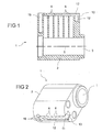
- Fig. 1 schematically shows a cylinder lock 1 comprising a recess 12 for a closure element 9 in a side view, which is formed according to the inventive design principle.
- the cylinder lock 1 has a cylinder housing 2, which is elliptical-like.
- the cylinder housing 2 has a cylinder bore 3, which extends through the entire length of the cylinder housing 2.
- a cylinder 4 is rotatably received.
- the cylinder 4 has a keyhole for receiving a key bit of a key.
- the key 17 and the key bit 18 are for example in Fig. 6 shown.
- the cylinder 4 has six lower channels 25 in which lower pins 7 are movably arranged, see, for example Fig.
- the cylinder housing 2 further has six upper channels 6, in which upper pins 20 are movably arranged, wherein the lower channels 25 can be arranged by rotation of the cylinder 4 in alignment with the upper channels 6. Both the lower channels 25 and the upper channels 6 extend perpendicular to the cylinder axis 5, wherein the lower pins 7 for interacting with the key bit, which is inserted into the keyhole, formed, and wherein in each upper channel 6, a spring element is arranged to exert a force on the upper pins 20 in the direction of the lower pins 7.
- the cylinder lock 1 further includes a closure member detachably secured to the cylinder housing 2 to cover openings of the upper channels 6 facing away from the cylinder 4 to provide a stop for the spring members.
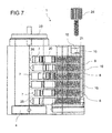
- the lower pins 7, the upper pins 20 and the Spring elements are in the Fig. 6 and 7 shown.
- the arrangement of the upper pins 20, the lower pins 7 and the spring elements is the same in all the inventive cylinder locks 1. It is possible that more than two upper pins 20 are arranged in the upper channel 6 of the cylinder housing 2 of the cylinder lock 1.
- the cylinder lock 1 may have one or more anti-rotation pin openings 19 in the cylinder housing for receiving cylinder housing anti-rotation pins, see Fig. 1 and 2 ,
- Fig. 2 shows the recess 12, which is designed for a sliding receiving a closure element 9 of the type, as in the Fig. 3 to 5 shown.
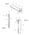
- the cylinder housing 2 of a cylinder lock 1 has first contact surfaces 11 and as shown in FIGS Fig. 3 to 5 it can be seen, the closure element 9 has second contact surfaces 10 for a sliding engagement with the first contact surfaces 11.
- the first contact surfaces 11 of the cylinder housing 2 and the second contact surfaces 10 of the closure element serve as a support for the spring elements 8, which are arranged in the upper channels 6 of the cylinder housing 2.
- the Fig. 3 to 5 show various views of a closure element 9 of a cylinder lock 1 according to the invention.
- the closure element 9 can slide into the recess 12 of the cylinder housing 2, see in FIG Fig. 2 to be moved into.
- the shutter member 9 has an L-shaped contour, comprising a main part 16 and a head 15, which is arranged inclined to the main part 16.
- Fig. 6 shows an exploded view of the cylinder lock 1, which is formed according to the inventive design principle.
- the cylinder lock 1 allows a simple, safe and fast Replacing the closure element 9, to allow easy adaptation of the cylinder lock 1 to a new or modified master key system.
- the mounting and dismounting of the closure element 9 can be carried out very easily. An installer can realize the mounting and dismounting of the closure element 9 only from one side of the cylinder lock 1.
- the cylinder lock 1 allows the installer to perform the replacement of the closure element 9 only with one hand.
- the closure element 9 has second contact surfaces 10.
- the second contact surfaces 10 of the closure element 9 engage in the first contact surfaces 11 of the cylinder housing 2, when the closure element slides onto the first contact surfaces 11 of the recess 12 of the cylinder housing 2, see Fig. 2 .
- the interlocking surfaces 10, 11 serve as a support for the spring elements 8. That means, the mating contact surfaces 10, 11 of both the cylinder housing 2 and the closure element 9 serve as a support for the force exerted by the spring elements 8 on the closure element 9 during actuation of the cylinder lock 1.
- the closure element 9 provides a stop for the spring elements 8 directly after the engagement of the first contact surfaces 11 of the cylinder housing 2 ready.
- the recess 12 and the closure element 9 are formed such that after a sliding engagement of the first contact surfaces 11 of the recess 12, the closure element is positively fixed in all directions in the recess 12, except for the opposite direction of the sliding direction.
- the first contact surfaces 11 of the cylinder housing 2 of the cylinder lock 1 extend perpendicular to the axis of the upper channels 6.
- the first contact surfaces 11 of the cylinder housing 2 are two parallel longitudinal grooves in the wall of the recess 12 of the cylinder housing 2. Accordingly, the second contact surfaces 10 of the closure element 9 are formed as guide means, in particular in the form of elongated projections.
- Such a construction of the cylinder housing 2, in particular the recess 12 of the cylinder housing 2, and the closure member 9 allows the closure member 9 can easily slide on the first contact surfaces 11 of the cylinder housing 2.
- the first contact surfaces 11, which are part of the longitudinal grooves of the recess 12 of the cylinder housing 2, form a slide rail for the closure element 9.
- Such a cylinder housing 2 and such a closure element 9 allow a simple, fast and secure engagement of the closure element 9 on the cylinder housing 2 of a Locking cylinder 1.
- the closure element 9 can be arranged inside the cylinder housing 2.
- the contour of the depression 12 corresponds to the main part 16 of the closure element 9.
- the depression 12 and the main part 16 of the closure element 9 are designed such that the main part 16 fits in a form-fitting manner into the depression 12.
- the cylinder lock 1 also has a fixing element 24, here in the form of a fixing screw, for releasably fixing the closure element 9 on the cylinder housing 2, in particular in the recess 12 of the cylinder housing 2.
- the fixing element 24 ensures that the closure element 9 is also fixed against the Aufgleitcardi of the closure element 9.
- the closure element 9 can be fixed very easily and quickly by the fixing element 24, since the installer can focus on the attachment of the fixing element 24. The installer does not need to keep the shutter member 9 on the cylinder housing 2 for fixing the fixing member 24 to the cylinder housing 2.
- the closure element 9 has a bore 14, which may be a threaded bore, and the cylinder housing 2 has a threaded bore 21 for receiving the fixing screw 24.
- the fixing screw 24 can be guided or screwed through the bore 14 of the closure element 9 into the threaded bore 21 of the cylinder housing 2.
- the fixing screw 24 ensures a very good and easy attachment of the closure element 9 to the cylinder housing 2 of the cylinder lock 1.
- the fixing screw 24 can be easily and quickly released to allow easy replacement of the pins 7, 20 and / or the spring elements 8 of the cylinder lock 1.
- the fixing screw 24 is advantageously a grub screw.
- the threaded bore 21 extends parallel to the axis 5 of the cylinder 4, in particular such that the access of the threaded bore 21 is arranged on the opposite side with respect to the insertion side of the key 17.
- This arrangement leads to increased security of the cylinder lock 1, because the fixing screw 24 is not accessible from the outside of the cylinder lock 1, which is installed for example in a door.
- the fixing element 24 may be a latching element, in particular a latching hook, on the closure element 9 in order to engage with a corresponding latching element of the cylinder housing 2.
- the cylinder lock 1 may also have means for releasing the locking elements of the corresponding locking elements of the cylinder housing 2.
- the closure element 9 has an L-shaped contour, comprising a main part 16 and a head 15, which is arranged at an angle, in this case at an angle of 90 °, to the main part 16.
- Such an L-shaped closure element 9, in conjunction with the cylinder housing 2, can define a stop position for the closure element 9 during the sliding of the closure element 9 on the first contact surfaces 11 onto the groove of the depression 12.
- the cylinder housing 2 has a stopper 13 for defining the stop position for the shutter member 9.
- the head 15 of the L-shaped shutter member 9 can be stopped by the stopper member 13 of the cylinder housing 2 to stop the sliding of the shutter member 9 and thus the position the closure element 9 on the cylinder housing 2, in particular in the recess 12 of the cylinder housing 2 to define.
- the main part 16 of the closure element 9 has a plate-like shape and is designed to cover the openings of the upper channels 6 of the cylinder housing 2.
- a core plate 23 is shown, which is fastened with screws 22 to the cylinder 4 on the opposite side for the opening for the key 17.
- Such a cylinder lock 1, as in the Fig. 1, 2 . 6 and 7 shown, allows easy and quick replacement of the pins 7, 20 of the cylinder lock 1, because the closure element 9, as in the Fig. 3 to 5 shown, can be quickly and easily replaced by the cylinder housing 2 of the cylinder lock 1.
Landscapes
- Lock And Its Accessories (AREA)
- Underground Structures, Protecting, Testing And Restoring Foundations (AREA)
- Refuge Islands, Traffic Blockers, Or Guard Fence (AREA)
Applications Claiming Priority (1)
| Application Number | Priority Date | Filing Date | Title |
|---|---|---|---|
| DE102011056724A DE102011056724A1 (de) | 2011-12-21 | 2011-12-21 | Zylinderschloss |
Publications (2)
| Publication Number | Publication Date |
|---|---|
| EP2607577A2 true EP2607577A2 (fr) | 2013-06-26 |
| EP2607577A3 EP2607577A3 (fr) | 2017-04-12 |
Family
ID=47115127
Family Applications (1)
| Application Number | Title | Priority Date | Filing Date |
|---|---|---|---|
| EP12006820.0A Withdrawn EP2607577A3 (fr) | 2011-12-21 | 2012-10-01 | Serrure cylindrique |
Country Status (4)
| Country | Link |
|---|---|
| EP (1) | EP2607577A3 (fr) |
| CN (1) | CN103174330B (fr) |
| DE (1) | DE102011056724A1 (fr) |
| TW (1) | TW201341638A (fr) |
Cited By (2)
| Publication number | Priority date | Publication date | Assignee | Title |
|---|---|---|---|---|
| CN103938935A (zh) * | 2014-03-27 | 2014-07-23 | 余义伦 | 一种高安全锁 |
| GB2608867A (en) * | 2021-07-15 | 2023-01-18 | Dongguan Quingxi Kwong Wah Lock Mfy Co Ltd | Lock core structure with quickly replaceable pins |
Families Citing this family (1)
| Publication number | Priority date | Publication date | Assignee | Title |
|---|---|---|---|---|
| CN106703518A (zh) * | 2015-07-30 | 2017-05-24 | 广东金点原子制锁有限公司 | 一种复合锁头 |
Citations (2)
| Publication number | Priority date | Publication date | Assignee | Title |
|---|---|---|---|---|
| EP0403551B1 (fr) | 1988-03-08 | 1993-05-26 | Assa Ab | Serrure a cylindre |
| DE102007051427A1 (de) | 2007-10-25 | 2009-04-30 | Dorma Gmbh & Co Kg | Zylinderschloss mit austauschbarer Spezifikation der Schließung |
Family Cites Families (11)
| Publication number | Priority date | Publication date | Assignee | Title |
|---|---|---|---|---|
| US2837908A (en) * | 1954-07-26 | 1958-06-10 | Segal Samuel | Cylinder lock |
| US4663839A (en) * | 1982-12-10 | 1987-05-12 | Best Lock Corporation | Cabinet lock |
| DE9205835U1 (de) * | 1992-05-04 | 1992-07-30 | Niemann, Hans Dieter, 5014 Kerpen | Schließzylinder |
| CN2586782Y (zh) * | 2002-09-25 | 2003-11-19 | 林鉴鸿 | 锁心 |
| DE10305692A1 (de) * | 2003-02-12 | 2004-08-26 | Aug. Winkhaus Gmbh & Co. Kg | Schließzylinder |
| DE102004006011A1 (de) * | 2004-02-06 | 2005-09-08 | Path Line(Ng's)Holdings Ltd. | Schließvorrichtung mit austauschbarem Zylinderstift |
| CN101377102A (zh) * | 2007-08-31 | 2009-03-04 | 新辉兴业有限公司 | 防盗弹子结构锁 |
| CN201141233Y (zh) * | 2007-11-19 | 2008-10-29 | 邓旭辉 | 弹子锁锁芯前卡扣式定位装置 |
| US20100180650A1 (en) * | 2009-01-16 | 2010-07-22 | Tien-Kao Liu | Anti-theft lock |
| US20100326150A1 (en) * | 2009-06-29 | 2010-12-30 | Chung Shu-Ling | Cylinder lock |
| CN201786100U (zh) * | 2009-12-04 | 2011-04-06 | 候洪兵 | 双面弹子锁 |
-
2011
- 2011-12-21 DE DE102011056724A patent/DE102011056724A1/de not_active Withdrawn
-
2012
- 2012-10-01 EP EP12006820.0A patent/EP2607577A3/fr not_active Withdrawn
- 2012-10-17 TW TW101138209A patent/TW201341638A/zh unknown
- 2012-12-21 CN CN201210563236.7A patent/CN103174330B/zh not_active Expired - Fee Related
Patent Citations (2)
| Publication number | Priority date | Publication date | Assignee | Title |
|---|---|---|---|---|
| EP0403551B1 (fr) | 1988-03-08 | 1993-05-26 | Assa Ab | Serrure a cylindre |
| DE102007051427A1 (de) | 2007-10-25 | 2009-04-30 | Dorma Gmbh & Co Kg | Zylinderschloss mit austauschbarer Spezifikation der Schließung |
Cited By (4)
| Publication number | Priority date | Publication date | Assignee | Title |
|---|---|---|---|---|
| CN103938935A (zh) * | 2014-03-27 | 2014-07-23 | 余义伦 | 一种高安全锁 |
| CN103938935B (zh) * | 2014-03-27 | 2018-10-23 | 余义伦 | 一种锁 |
| GB2608867A (en) * | 2021-07-15 | 2023-01-18 | Dongguan Quingxi Kwong Wah Lock Mfy Co Ltd | Lock core structure with quickly replaceable pins |
| GB2608867B (en) * | 2021-07-15 | 2025-02-26 | Dongguan Quingxi Kwong Wah Lock Mfy Co Ltd | Lock core structure with quickly replaceable pins |
Also Published As
| Publication number | Publication date |
|---|---|
| TW201341638A (zh) | 2013-10-16 |
| CN103174330A (zh) | 2013-06-26 |
| EP2607577A3 (fr) | 2017-04-12 |
| CN103174330B (zh) | 2016-04-20 |
| DE102011056724A1 (de) | 2013-06-27 |
Similar Documents
| Publication | Publication Date | Title |
|---|---|---|
| EP3348758A1 (fr) | Loqueteaux à billes | |
| EP2920804B1 (fr) | Contacteur de porte | |
| DE29606992U1 (de) | Für eine Rastmontage eingerichteter Stangenverschluß | |
| DE4006707C2 (de) | Vorreiberverschluß | |
| EP2607577A2 (fr) | Serrure cylindrique | |
| EP3535824B1 (fr) | Support de jeu de barres et ensemble correspondant | |
| EP2754790B1 (fr) | Element avec ferrure auto-centrage pour fenêtres ou portes | |
| EP2033266B1 (fr) | Borne de connexion de conducteur | |
| EP1045098A1 (fr) | Crémone à tige ronde | |
| EP2792822A2 (fr) | Codage via des poutres de blocage | |
| DE10309946B4 (de) | Schloß | |
| EP1837460B1 (fr) | Ferrure pour ouvrant coulissant et système de ferrure | |
| EP3179017B1 (fr) | Insert de gâche pour libération conditionnelle d'un bec de cane d'un mécanisme de verrou de porte | |
| EP1662627B1 (fr) | Dispositif pour la fixation détachable d'un boîtier d'appareil à un rail profilé | |
| EP2053184B1 (fr) | Serrure cylindrique à combinaison modifiable | |
| DE102013205061A1 (de) | Bedienungsmittel für eine Platte, Kombination zweier Bedienungsmittel und Verfahren zum klemmfesten Positionieren des Bedienungsmittels an einer Platte | |
| DE9210795U1 (de) | Sicherheitsbeschlag für mit einem Profilschließzylinder versehene Türschlösser | |
| EP3514302B1 (fr) | Ferrure de porte et procédé de montage d'une ferrure de porte | |
| EP2514892B1 (fr) | Système de fixation d'une partie de ferrure | |
| DE19844095C1 (de) | Anschlußleiste für die Telekommunikationstechnik | |
| DE60002561T2 (de) | Zusatzverriegelung für aktenkoffer, tragbare rechner oder dergleichen | |
| DE102016109214B4 (de) | Verriegelungselement | |
| DE3305209C3 (de) | Türschloß | |
| AT404376B (de) | Riegelschloss | |
| EP0945574B1 (fr) | Charnière pour portes, fenêtres ou similaires |
Legal Events
| Date | Code | Title | Description |
|---|---|---|---|
| AK | Designated contracting states |
Kind code of ref document: A2 Designated state(s): AL AT BE BG CH CY CZ DE DK EE ES FI FR GB GR HR HU IE IS IT LI LT LU LV MC MK MT NL NO PL PT RO RS SE SI SK SM TR |
|
| AX | Request for extension of the european patent |
Extension state: BA ME |
|
| PUAI | Public reference made under article 153(3) epc to a published international application that has entered the european phase |
Free format text: ORIGINAL CODE: 0009012 |
|
| RAP1 | Party data changed (applicant data changed or rights of an application transferred) |
Owner name: DORMA DEUTSCHLAND GMBH |
|
| PUAL | Search report despatched |
Free format text: ORIGINAL CODE: 0009013 |
|
| AK | Designated contracting states |
Kind code of ref document: A3 Designated state(s): AL AT BE BG CH CY CZ DE DK EE ES FI FR GB GR HR HU IE IS IT LI LT LU LV MC MK MT NL NO PL PT RO RS SE SI SK SM TR |
|
| AX | Request for extension of the european patent |
Extension state: BA ME |
|
| RIC1 | Information provided on ipc code assigned before grant |
Ipc: E05B 27/00 20060101ALI20170303BHEP Ipc: E05B 9/04 20060101AFI20170303BHEP |
|
| RAP1 | Party data changed (applicant data changed or rights of an application transferred) |
Owner name: DORMAKABA DEUTSCHLAND GMBH |
|
| STAA | Information on the status of an ep patent application or granted ep patent |
Free format text: STATUS: REQUEST FOR EXAMINATION WAS MADE |
|
| 17P | Request for examination filed |
Effective date: 20171011 |
|
| RBV | Designated contracting states (corrected) |
Designated state(s): AL AT BE BG CH CY CZ DE DK EE ES FI FR GB GR HR HU IE IS IT LI LT LU LV MC MK MT NL NO PL PT RO RS SE SI SK SM TR |
|
| STAA | Information on the status of an ep patent application or granted ep patent |
Free format text: STATUS: EXAMINATION IS IN PROGRESS |
|
| 17Q | First examination report despatched |
Effective date: 20180208 |
|
| STAA | Information on the status of an ep patent application or granted ep patent |
Free format text: STATUS: THE APPLICATION HAS BEEN WITHDRAWN |
|
| 18W | Application withdrawn |
Effective date: 20180620 |