EP0945574B1 - Charnière pour portes, fenêtres ou similaires - Google Patents
Charnière pour portes, fenêtres ou similaires Download PDFInfo
- Publication number
- EP0945574B1 EP0945574B1 EP99102940A EP99102940A EP0945574B1 EP 0945574 B1 EP0945574 B1 EP 0945574B1 EP 99102940 A EP99102940 A EP 99102940A EP 99102940 A EP99102940 A EP 99102940A EP 0945574 B1 EP0945574 B1 EP 0945574B1
- Authority
- EP
- European Patent Office
- Prior art keywords
- hinge
- fastening
- covering cap
- cap
- strap
- Prior art date
- Legal status (The legal status is an assumption and is not a legal conclusion. Google has not performed a legal analysis and makes no representation as to the accuracy of the status listed.)
- Expired - Lifetime
Links
Images


Classifications
-
- E—FIXED CONSTRUCTIONS
- E05—LOCKS; KEYS; WINDOW OR DOOR FITTINGS; SAFES
- E05D—HINGES OR SUSPENSION DEVICES FOR DOORS, WINDOWS OR WINGS
- E05D11/00—Additional features or accessories of hinges
- E05D11/0054—Covers, e.g. for protection
-
- E—FIXED CONSTRUCTIONS
- E05—LOCKS; KEYS; WINDOW OR DOOR FITTINGS; SAFES
- E05D—HINGES OR SUSPENSION DEVICES FOR DOORS, WINDOWS OR WINGS
- E05D7/00—Hinges or pivots of special construction
- E05D7/04—Hinges adjustable relative to the wing or the frame
- E05D7/0415—Hinges adjustable relative to the wing or the frame with adjusting drive means
- E05D7/0423—Screw-and-nut mechanisms
-
- E—FIXED CONSTRUCTIONS
- E05—LOCKS; KEYS; WINDOW OR DOOR FITTINGS; SAFES
- E05D—HINGES OR SUSPENSION DEVICES FOR DOORS, WINDOWS OR WINGS
- E05D7/00—Hinges or pivots of special construction
- E05D7/04—Hinges adjustable relative to the wing or the frame
- E05D2007/0484—Hinges adjustable relative to the wing or the frame in a radial direction
-
- E—FIXED CONSTRUCTIONS
- E05—LOCKS; KEYS; WINDOW OR DOOR FITTINGS; SAFES
- E05Y—INDEXING SCHEME ASSOCIATED WITH SUBCLASSES E05D AND E05F, RELATING TO CONSTRUCTION ELEMENTS, ELECTRIC CONTROL, POWER SUPPLY, POWER SIGNAL OR TRANSMISSION, USER INTERFACES, MOUNTING OR COUPLING, DETAILS, ACCESSORIES, AUXILIARY OPERATIONS NOT OTHERWISE PROVIDED FOR, APPLICATION THEREOF
- E05Y2900/00—Application of doors, windows, wings or fittings thereof
- E05Y2900/10—Application of doors, windows, wings or fittings thereof for buildings or parts thereof
- E05Y2900/13—Type of wing
- E05Y2900/132—Doors
-
- E—FIXED CONSTRUCTIONS
- E05—LOCKS; KEYS; WINDOW OR DOOR FITTINGS; SAFES
- E05Y—INDEXING SCHEME ASSOCIATED WITH SUBCLASSES E05D AND E05F, RELATING TO CONSTRUCTION ELEMENTS, ELECTRIC CONTROL, POWER SUPPLY, POWER SIGNAL OR TRANSMISSION, USER INTERFACES, MOUNTING OR COUPLING, DETAILS, ACCESSORIES, AUXILIARY OPERATIONS NOT OTHERWISE PROVIDED FOR, APPLICATION THEREOF
- E05Y2900/00—Application of doors, windows, wings or fittings thereof
- E05Y2900/10—Application of doors, windows, wings or fittings thereof for buildings or parts thereof
- E05Y2900/13—Type of wing
- E05Y2900/148—Windows
Definitions
- the invention relates to a tape of the preamble of claim 1 corresponding type.
- the two parts of which are displaceable relative to each other by a perpendicular to the hinge pin axis and parallel to the wing plane screw assembly serves as a trough-shaped metal cap, which is open to the wing and the hinge pin facing sides open.
- a longitudinal distance from one another having fastening projections are provided.
- the first and the second hinge plate part are at a distance from the wing surface corresponding Jacobbefest Trentsvorsprünge intended.
- the mounting of the cap is made by placing the same in a position in which the fastening projections of the hinge and the cover are past each other. By a subsequent displacement of the cap to the hinge pin towards the mounting projections are engaged with each other, so that the cap is fixed.
- a protruding pin is provided on the side facing the hinge pin on the parallel to the wing part wall of the cap, which engages in a provided on the leaf hinge part recess when the cap is in its deferred position.
- the pin is provided on its side facing the wing with a plurality of locking lugs, which are brought when sliding the cover with engaged in the recess counter-locking surfaces in engagement.
- a recess is incorporated, in which the tapered end of an operable from the underside of the hinge strap screw is screwed to secure the cap in its pushed position.
- a closure which can be closed by means of a plug is provided in the narrow side of the covering cap extending parallel to the hinge pin, by means of which the screw arrangement can be actuated by means of a tool.
- the invention is therefore an object of the invention to provide a tape in which the cap is mounted in a simple manner and their sufficiently solid, play-free seat is guaranteed even after several Aufsetzvor réellen, so that dispenses with additional openings for actuation on the hinge tab any existing adjusting devices can be.
- the fixation of the cap takes place in that the fastening means are designed such that at least provided on the cap second mounting projections and / or the cap even when placed and / or during subsequent displacement transversely to the touchdown be deformed. If the elastic deformation already takes place when the cover cap is placed on it, it is already secured by the hinge strap before being moved for fixation against an automatic fall-off. The assembly of the cap on the hinge plate is thereby facilitated. In addition, a clamping effect, which prevents rattling of the cap.
- the cap can be mounted as often as desired, so that a hole in the cap for operating the screw assembly is unnecessary.
- the hinge flap according to claim 3 formed in two parts, wherein the first part is fastened to the frame or wing and serves as a fastener and the second, substantially plate-shaped and upstanding from the plate plane bead-shaped thickening part formed as adjustment and between the first part and the surface of the wing or the frame can be fixed, the first fastening projections are preferably formed by paragraphs provided on the first part along the longitudinal sides thereof. As a result of this refinement, the fastening projections are particularly easy to realize in terms of manufacturing technology.
- an undercut behind which the facing edge of the cap is inserted.
- these means preferably comprise a locking surface, which is provided on the side facing the hinge strap and from the thickening of the hinge strap irrit and behind which optionally a with an open wing accessible locking element is displaceable (claim 6).
- the locking element is preferably a self-tapping screw engaging with its thread in the first hinge plate part (claim 7).
- the cap is preferably made of metal or plastic according to claim 8.
- the required elasticity and desired strength parameters can be easily adjusted by an appropriate choice of material.
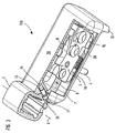
- hinge tab of a tape is designed as an adjustable hinge tab, which is usually attached to a sash, not shown in the drawing.
- the hinge tab 100 is connected to the other, likewise not shown in the drawing hinge tabs for fastening the tape to the frame via a hinge pin, again not shown, which is mounted in a vertical longitudinal recess 2, which in turn is incorporated into a bead-like thickening 1.
- the hinge tab 100 is formed in two parts. It comprises a fastening part 3 and an adjusting part 6.
- the fastening part 3 with two guide pins 4 (only one of which is visible for example in Fig. 3) and six countersunk screws, not shown in the drawing, which are screwed through corresponding holes 5 of the fixing part 3 in the wing, on the wing assembled.
- the adjustment part 6 consists essentially of a rectangular plate 7, whose longer sides extend perpendicular to the hinge axis designated S and the in the assembled state rests flat with its back on the wing, not shown in the drawing. At the left in Fig. 1 to 3 shown on the narrow side of the plate 7, the bead-shaped thickening 1 is formed.
- the plate 7 has in its longitudinal direction extending through recesses 8 in the form of longitudinal slots, which passes through the attachment part 3 of the hinge strap 100 with its guide pin 4 and the fastening screws, not shown in the drawing.
- the recesses 8 have a length which allow a relative displacement of the fastening part 3 and the adjusting part 6.
- the displacement of the fastening part 3 and the adjusting part 6 to each other is used a perpendicular to the hinge axis S extending cap screw 9, which has a cylindrical head 10 with polygon socket in the embodiment shown in the drawing.
- the head 10 is mounted in a provided in the fastening part 3 recess 11 under axial fixation.
- a longitudinal recess 13 is incorporated in the fastening part 3, which is penetrated by a threaded part 14, in which the head screw 9 engages and which is connected to the adjustment part 6 of the hinge strap 100.
- first fixing projections 15 are arranged at its two sides running perpendicular to the hinge axis S, the undersides 16 of which have a certain distance from the top 7 'of the plate 7 and extend parallel thereto.
- the tops 17 of the attachment projections 15 are formed sloping towards the edges.
- the first mounting projections 15 are interrupted by two projecting to the center of the fastening part 3 recesses 18, of which in Figs. 1 to 3, only the facing the viewer is recognizable. They serve to attach a cap 19, which completely covers the top of the band tab 100 to the bead-shaped thickening 1.
- the cap 19 comprises second fastening projections 20 which are arranged such that the cap is placed under the passage of the bead-shaped thickening 1 facing the front part of the fastening projections through the recesses 18 on the hinge tab 100.
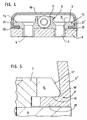
- the extent of the first fastening projections 15 in the direction of the hinge axis S is dimensioned such that the Aufsetzvorgang the lateral Abdeckkappenwandungen 21,21 'elastically slightly spread outwards.
- the distance of the lateral edges 15 'of the first fastening projections 15 has - in other words - the inner spacing of the lateral Abdeckkappenwanditch 21,21' on an oversize. The latter is illustrated by the projection shown in FIG.
- the placement process is facilitated by the sloping down to the edges top 17 of the first mounting projections 15.
- the thickness of the second fastening projections 20 is dimensioned such that they are displaceable after the complete placement of the cap 19 in the gap formed between the bottom 16 of the first fastening projections 15 and the top 7 'of the plate 7.
- the cap 19 can therefore be moved so far to the bead-shaped thickening 1 out until an opposite on the hinge axis parallel side of the cap 19 provided approach 22 abuts the rear edge of the adjustment 6.
- the length of the cap 19 is dimensioned so that in this position with its side facing the hinge axis S on the bead-shaped Verdikkung 1 before seen, parallel to the hinge axis S extending undercut 23 engages.
- the adjusting part 6 has a bore 27 projecting obliquely forwards from the rear, in which a locking screw 26 can be inserted.
- the cap 19 includes an equally extending bore 24 which forms a locking surface 25 and in which the self-tapping locking screw 26 is screwed with the wing open.
Landscapes
- Engineering & Computer Science (AREA)
- Mechanical Engineering (AREA)
- Hinges (AREA)
- Adhesive Tapes (AREA)
- Hinge Accessories (AREA)
- Refrigerator Housings (AREA)
- Pens And Brushes (AREA)
- Liquid Crystal (AREA)
- Wing Frames And Configurations (AREA)
Claims (8)
- Charnière pour portes, fenêtres ou similaires ayant 2 pattes de charnière dont l'une peut être fixée sur le cadre et l'autre (100) sur le vantail par des éléments de fixation, les pattes de charnière étant reliées au moyen d'un boulon, formant l'axe de charnière (S), monté dans un logement (2) prévu dans un renflement en forme de bourrelet (1) d'une patte de charnière (100) et ayant au moins un capuchon (19) pouvant être monté sur une (100) des pattes de charnière et la recouvrant au moins partiellement, au moins une première saillie de fixation (15) étant prévue sur la patte de charnière (100) et au moins une deuxième saillie de fixation (20) étant prévue sur le capuchon (19) pour permettre une mise en place de celui-ci dans une direction sensiblement perpendiculaire au plan de fixation, puis un déplacement dans une direction parallèle au plan de fixation et transversale à l'axe de charnière (S) en faisant s'engager mutuellement par l'arrière les saillies de fixation (15, 20), la distance des roues latérales (15') des premières saillies de fixation (15) par rapport à la distance intérieure des parois latérales du capuchon (21, 21') présentant un excès de sorte que, dans le cas d'un processus de placement, les parois latérales du capuchon (21, 21') soient écartées facilement vers l'extérieur de manière élastique.
- Charnière selon la revendication 1,
caractérisée en ce que
les premières saillies de fixation (15) présentent au moins un évidement (18) à travers lequel une deuxième saillie de fixation (20) peut, dans la direction de placement, être mise en place dans la position permettant le déplacement du capuchon (19). - Charnière selon la revendication 1 ou 2,
caractérisée en ce que
la patte de charnière (100) est réalisée en deux parties : la partie de fixation (3) fixée sur le cadre du vantail et la partie de réglage (6) en forme de plaque qui porte le renflement en forme de bourrelet (1) dépassant du plan de plaque et qui peut être fixée entre la partie de fixation (3) et la surface du vantail ou du cadre, et les premières saillies de fixation (15) sont formées par des épaulements prévus sur des faces de la partie de fixation (3) s'étendant perpendiculairement à l'axe de charnière (5). - Charnière selon l'une des revendications 1 à 3,
caractérisée en ce que
la face du renflement (1) en forme de bourrelet , en regard du capuchon (19), présente une découpe arrière (23), derrière laquelle peut être introduit le bord du capuchon (19) en regard de celle-ci. - Charnière selon l'une des revendications 1 à 4,
caractérisée par
des moyens pour bloquer le capuchon (19) mis en place sur la patte de charnière (100). - Charnière selon la revendication 5,
caractérisée en ce que
ces moyens comprennent une surface de blocage (25) sur la face du capuchon (19) en regard de la patte de charnière (100) et partant de son renflement (1), et l'élément de blocage, accessible lorsque le vantail est ouvert, peut être mis en place derrière cette surface de blocage (25). - Charnière selon la revendication 6,
caractérisée en ce que
l'élément de blocage est une vis de blocage (26) auto-coupante insérée dans la partie de réglage (6). - Charnière selon l'une des revendications 1 à 7,
caractérisée en ce que
le capuchon (19) est en métal ou en matière plastique.
Applications Claiming Priority (2)
| Application Number | Priority Date | Filing Date | Title |
|---|---|---|---|
| DE29805470U DE29805470U1 (de) | 1998-03-25 | 1998-03-25 | Band für Türen, Fenster o.dgl. |
| DE29805470U | 1998-03-25 |
Publications (3)
| Publication Number | Publication Date |
|---|---|
| EP0945574A2 EP0945574A2 (fr) | 1999-09-29 |
| EP0945574A3 EP0945574A3 (fr) | 2002-12-11 |
| EP0945574B1 true EP0945574B1 (fr) | 2006-09-27 |
Family
ID=8054790
Family Applications (1)
| Application Number | Title | Priority Date | Filing Date |
|---|---|---|---|
| EP99102940A Expired - Lifetime EP0945574B1 (fr) | 1998-03-25 | 1999-02-13 | Charnière pour portes, fenêtres ou similaires |
Country Status (5)
| Country | Link |
|---|---|
| EP (1) | EP0945574B1 (fr) |
| AT (1) | ATE340912T1 (fr) |
| DE (2) | DE29805470U1 (fr) |
| DK (1) | DK0945574T3 (fr) |
| ES (1) | ES2274590T3 (fr) |
Families Citing this family (1)
| Publication number | Priority date | Publication date | Assignee | Title |
|---|---|---|---|---|
| DE20316622U1 (de) * | 2003-10-29 | 2005-03-10 | Dr. Hahn Gmbh & Co. Kg | Band für Türen, Fenster o.dgl. |
Family Cites Families (3)
| Publication number | Priority date | Publication date | Assignee | Title |
|---|---|---|---|---|
| DE3601496A1 (de) * | 1986-01-20 | 1987-07-23 | Hahn Gmbh & Co Kg Dr | Band fuer tueren, fenster und dergleichen |
| DE9413891U1 (de) * | 1994-08-27 | 1995-12-21 | Dr. Hahn GmbH & Co. KG., 41189 Mönchengladbach | Band für Türen, Fenster u.dgl. |
| DE19642638C5 (de) * | 1996-10-16 | 2004-04-01 | Simonswerk, Gmbh | Türband |
-
1998
- 1998-03-25 DE DE29805470U patent/DE29805470U1/de not_active Expired - Lifetime
-
1999
- 1999-02-13 EP EP99102940A patent/EP0945574B1/fr not_active Expired - Lifetime
- 1999-02-13 DE DE59913868T patent/DE59913868D1/de not_active Expired - Lifetime
- 1999-02-13 AT AT99102940T patent/ATE340912T1/de not_active IP Right Cessation
- 1999-02-13 DK DK99102940T patent/DK0945574T3/da active
- 1999-02-13 ES ES99102940T patent/ES2274590T3/es not_active Expired - Lifetime
Also Published As
| Publication number | Publication date |
|---|---|
| EP0945574A3 (fr) | 2002-12-11 |
| EP0945574A2 (fr) | 1999-09-29 |
| DK0945574T3 (da) | 2007-02-05 |
| DE29805470U1 (de) | 1999-08-12 |
| DE59913868D1 (de) | 2006-11-09 |
| ATE340912T1 (de) | 2006-10-15 |
| ES2274590T3 (es) | 2007-05-16 |
Similar Documents
| Publication | Publication Date | Title |
|---|---|---|
| EP2725174B1 (fr) | Module de charnière | |
| DE69921874T2 (de) | Scharnier mit einer durch Nocken querverstellbaren Grundplatte | |
| EP1040245B1 (fr) | Tourniquet pour portes, volets ou similaires a paroi epaisse | |
| DE69805903T2 (de) | Beschlag mit einstellbarem Riegel für Schiebeflügel | |
| DE2445834A1 (de) | Schliesschlitzausbildung in einer tuerzarge | |
| DE10309946B4 (de) | Schloß | |
| DE4341422C2 (de) | Topfscharnier | |
| EP1666688A2 (fr) | Charnière pour fenêtres, portes et similaires | |
| EP2514892B1 (fr) | Système de fixation d'une partie de ferrure | |
| DE10309947B4 (de) | Schloß | |
| DE202007006349U1 (de) | Bandanordnung | |
| EP1837460A2 (fr) | Ferrure pour ouvrant coulissant et système de ferrure | |
| DE29600891U1 (de) | Sicherungseinrichtung | |
| DE29906659U1 (de) | Schließteil zum Einsetzen in eine hinterschnittene Aufnahmenut eines Rahmens für Fenster oder Türen | |
| DE19857384C2 (de) | Befestigungsmittel zum Verbinden eines Flügelrahmens mit einem Blendrahmen zu einem nicht öffenbaren Fenster | |
| EP2896772B1 (fr) | Partie de bande d'une bande destinée à la fixation articulée d'un battant sur un cadre | |
| EP0945574A2 (fr) | Charnière pour portes, fenêtres ou similaires | |
| EP0665355A2 (fr) | Charnière pour portes coupe-feu | |
| EP0791704A1 (fr) | Gâche | |
| DE10354310A1 (de) | Dichtung insbesondere selbsttätig absenkende Bodendichtung für Türen | |
| EP0843061B1 (fr) | Ferrure pour fenêtre | |
| EP2730732A2 (fr) | Charnière pour portes, fenêtres ou analogues | |
| DE202013104273U1 (de) | System, umfassend ein Hohlprofil und einen Bandlappen eines Bandes, Bandlappen dieses Systems sowie Justierstück dieses Bandlappens | |
| DE29512995U1 (de) | Anschlagvorrichtung für Türen oder Tore | |
| DE29620345U1 (de) | Band für Türen, Fenstern u.dgl. |
Legal Events
| Date | Code | Title | Description |
|---|---|---|---|
| PUAI | Public reference made under article 153(3) epc to a published international application that has entered the european phase |
Free format text: ORIGINAL CODE: 0009012 |
|
| AK | Designated contracting states |
Kind code of ref document: A2 Designated state(s): AT BE CH CY DE DK ES FI FR GB GR IE IT LI LU MC NL PT SE |
|
| AX | Request for extension of the european patent |
Free format text: AL;LT;LV;MK;RO;SI |
|
| PUAL | Search report despatched |
Free format text: ORIGINAL CODE: 0009013 |
|
| AK | Designated contracting states |
Kind code of ref document: A3 Designated state(s): AT BE CH CY DE DK ES FI FR GB GR IE IT LI LU MC NL PT SE |
|
| AX | Request for extension of the european patent |
Free format text: AL;LT;LV;MK;RO;SI |
|
| 17P | Request for examination filed |
Effective date: 20030426 |
|
| AKX | Designation fees paid |
Designated state(s): AT BE CY DE DK ES FR GB GR IE IT NL PT SE |
|
| 17Q | First examination report despatched |
Effective date: 20031117 |
|
| GRAP | Despatch of communication of intention to grant a patent |
Free format text: ORIGINAL CODE: EPIDOSNIGR1 |
|
| GRAS | Grant fee paid |
Free format text: ORIGINAL CODE: EPIDOSNIGR3 |
|
| GRAA | (expected) grant |
Free format text: ORIGINAL CODE: 0009210 |
|
| AK | Designated contracting states |
Kind code of ref document: B1 Designated state(s): AT BE DE DK ES FR GB GR IE IT NL PT SE |
|
| PG25 | Lapsed in a contracting state [announced via postgrant information from national office to epo] |
Ref country code: IT Free format text: LAPSE BECAUSE OF FAILURE TO SUBMIT A TRANSLATION OF THE DESCRIPTION OR TO PAY THE FEE WITHIN THE PRESCRIBED TIME-LIMIT;WARNING: LAPSES OF ITALIAN PATENTS WITH EFFECTIVE DATE BEFORE 2007 MAY HAVE OCCURRED AT ANY TIME BEFORE 2007. THE CORRECT EFFECTIVE DATE MAY BE DIFFERENT FROM THE ONE RECORDED. Effective date: 20060927 Ref country code: IE Free format text: LAPSE BECAUSE OF FAILURE TO SUBMIT A TRANSLATION OF THE DESCRIPTION OR TO PAY THE FEE WITHIN THE PRESCRIBED TIME-LIMIT Effective date: 20060927 |
|
| REG | Reference to a national code |
Ref country code: GB Ref legal event code: FG4D Free format text: NOT ENGLISH |
|
| REG | Reference to a national code |
Ref country code: IE Ref legal event code: FG4D Free format text: LANGUAGE OF EP DOCUMENT: GERMAN |
|
| REF | Corresponds to: |
Ref document number: 59913868 Country of ref document: DE Date of ref document: 20061109 Kind code of ref document: P |
|
| REG | Reference to a national code |
Ref country code: GR Ref legal event code: EP Ref document number: 20060403918 Country of ref document: GR |
|
| REG | Reference to a national code |
Ref country code: SE Ref legal event code: TRGR |
|
| GBT | Gb: translation of ep patent filed (gb section 77(6)(a)/1977) |
Effective date: 20070104 |
|
| REG | Reference to a national code |
Ref country code: DK Ref legal event code: T3 |
|
| PG25 | Lapsed in a contracting state [announced via postgrant information from national office to epo] |
Ref country code: PT Free format text: LAPSE BECAUSE OF FAILURE TO SUBMIT A TRANSLATION OF THE DESCRIPTION OR TO PAY THE FEE WITHIN THE PRESCRIBED TIME-LIMIT Effective date: 20070313 |
|
| ET | Fr: translation filed | ||
| REG | Reference to a national code |
Ref country code: IE Ref legal event code: FD4D |
|
| REG | Reference to a national code |
Ref country code: ES Ref legal event code: FG2A Ref document number: 2274590 Country of ref document: ES Kind code of ref document: T3 |
|
| PLBE | No opposition filed within time limit |
Free format text: ORIGINAL CODE: 0009261 |
|
| STAA | Information on the status of an ep patent application or granted ep patent |
Free format text: STATUS: NO OPPOSITION FILED WITHIN TIME LIMIT |
|
| 26N | No opposition filed |
Effective date: 20070628 |
|
| PGFP | Annual fee paid to national office [announced via postgrant information from national office to epo] |
Ref country code: SE Payment date: 20090206 Year of fee payment: 11 |
|
| PGFP | Annual fee paid to national office [announced via postgrant information from national office to epo] |
Ref country code: ES Payment date: 20100312 Year of fee payment: 12 Ref country code: DK Payment date: 20100211 Year of fee payment: 12 |
|
| PGFP | Annual fee paid to national office [announced via postgrant information from national office to epo] |
Ref country code: IT Payment date: 20100218 Year of fee payment: 12 Ref country code: FR Payment date: 20100223 Year of fee payment: 12 |
|
| PGFP | Annual fee paid to national office [announced via postgrant information from national office to epo] |
Ref country code: GB Payment date: 20100202 Year of fee payment: 12 Ref country code: DE Payment date: 20100228 Year of fee payment: 12 Ref country code: BE Payment date: 20100215 Year of fee payment: 12 Ref country code: AT Payment date: 20100212 Year of fee payment: 12 |
|
| PGFP | Annual fee paid to national office [announced via postgrant information from national office to epo] |
Ref country code: NL Payment date: 20100209 Year of fee payment: 12 |
|
| EUG | Se: european patent has lapsed | ||
| PGFP | Annual fee paid to national office [announced via postgrant information from national office to epo] |
Ref country code: GR Payment date: 20100129 Year of fee payment: 12 |
|
| BERE | Be: lapsed |
Owner name: DR. HAHN G.M.B.H. & CO. KG Effective date: 20110228 |
|
| REG | Reference to a national code |
Ref country code: NL Ref legal event code: V1 Effective date: 20110901 |
|
| REG | Reference to a national code |
Ref country code: DK Ref legal event code: EBP |
|
| GBPC | Gb: european patent ceased through non-payment of renewal fee |
Effective date: 20110213 |
|
| REG | Reference to a national code |
Ref country code: FR Ref legal event code: ST Effective date: 20111102 |
|
| PG25 | Lapsed in a contracting state [announced via postgrant information from national office to epo] |
Ref country code: GR Free format text: LAPSE BECAUSE OF NON-PAYMENT OF DUE FEES Effective date: 20110902 Ref country code: BE Free format text: LAPSE BECAUSE OF NON-PAYMENT OF DUE FEES Effective date: 20110228 Ref country code: AT Free format text: LAPSE BECAUSE OF NON-PAYMENT OF DUE FEES Effective date: 20110213 |
|
| PG25 | Lapsed in a contracting state [announced via postgrant information from national office to epo] |
Ref country code: IT Free format text: LAPSE BECAUSE OF NON-PAYMENT OF DUE FEES Effective date: 20110213 Ref country code: NL Free format text: LAPSE BECAUSE OF NON-PAYMENT OF DUE FEES Effective date: 20110901 |
|
| PG25 | Lapsed in a contracting state [announced via postgrant information from national office to epo] |
Ref country code: FR Free format text: LAPSE BECAUSE OF NON-PAYMENT OF DUE FEES Effective date: 20110228 |
|
| PG25 | Lapsed in a contracting state [announced via postgrant information from national office to epo] |
Ref country code: GB Free format text: LAPSE BECAUSE OF NON-PAYMENT OF DUE FEES Effective date: 20110213 |
|
| REG | Reference to a national code |
Ref country code: DE Ref legal event code: R119 Ref document number: 59913868 Country of ref document: DE Effective date: 20110901 |
|
| REG | Reference to a national code |
Ref country code: ES Ref legal event code: FD2A Effective date: 20120411 |
|
| PG25 | Lapsed in a contracting state [announced via postgrant information from national office to epo] |
Ref country code: ES Free format text: LAPSE BECAUSE OF NON-PAYMENT OF DUE FEES Effective date: 20110214 |
|
| PG25 | Lapsed in a contracting state [announced via postgrant information from national office to epo] |
Ref country code: SE Free format text: LAPSE BECAUSE OF NON-PAYMENT OF DUE FEES Effective date: 20100214 |
|
| PG25 | Lapsed in a contracting state [announced via postgrant information from national office to epo] |
Ref country code: DE Free format text: LAPSE BECAUSE OF NON-PAYMENT OF DUE FEES Effective date: 20110901 |