EP2607889A2 - Microscope à fluorescence pour observation d'image à fluorescence multiple, procédé d'observation d'image à fluorescence l'utilisant, et système d'observation d'image à fluorescence multiple - Google Patents
Microscope à fluorescence pour observation d'image à fluorescence multiple, procédé d'observation d'image à fluorescence l'utilisant, et système d'observation d'image à fluorescence multiple Download PDFInfo
- Publication number
- EP2607889A2 EP2607889A2 EP11818416.7A EP11818416A EP2607889A2 EP 2607889 A2 EP2607889 A2 EP 2607889A2 EP 11818416 A EP11818416 A EP 11818416A EP 2607889 A2 EP2607889 A2 EP 2607889A2
- Authority
- EP
- European Patent Office
- Prior art keywords
- image
- light
- light source
- filter
- excitation
- Prior art date
- Legal status (The legal status is an assumption and is not a legal conclusion. Google has not performed a legal analysis and makes no representation as to the accuracy of the status listed.)
- Withdrawn
Links
Images









Classifications
-
- G—PHYSICS
- G01—MEASURING; TESTING
- G01N—INVESTIGATING OR ANALYSING MATERIALS BY DETERMINING THEIR CHEMICAL OR PHYSICAL PROPERTIES
- G01N21/00—Investigating or analysing materials by the use of optical means, i.e. using sub-millimetre waves, infrared, visible or ultraviolet light
- G01N21/62—Systems in which the material investigated is excited whereby it emits light or causes a change in wavelength of the incident light
- G01N21/63—Systems in which the material investigated is excited whereby it emits light or causes a change in wavelength of the incident light optically excited
- G01N21/64—Fluorescence; Phosphorescence
-
- G—PHYSICS
- G02—OPTICS
- G02B—OPTICAL ELEMENTS, SYSTEMS OR APPARATUS
- G02B21/00—Microscopes
- G02B21/0004—Microscopes specially adapted for specific applications
- G02B21/002—Scanning microscopes
- G02B21/0024—Confocal scanning microscopes (CSOMs) or confocal "macroscopes"; Accessories which are not restricted to use with CSOMs, e.g. sample holders
- G02B21/0052—Optical details of the image generation
- G02B21/0076—Optical details of the image generation arrangements using fluorescence or luminescence
-
- G—PHYSICS
- G02—OPTICS
- G02B—OPTICAL ELEMENTS, SYSTEMS OR APPARATUS
- G02B21/00—Microscopes
-
- G—PHYSICS
- G02—OPTICS
- G02B—OPTICAL ELEMENTS, SYSTEMS OR APPARATUS
- G02B21/00—Microscopes
- G02B21/0004—Microscopes specially adapted for specific applications
- G02B21/002—Scanning microscopes
- G02B21/0024—Confocal scanning microscopes (CSOMs) or confocal "macroscopes"; Accessories which are not restricted to use with CSOMs, e.g. sample holders
- G02B21/0052—Optical details of the image generation
- G02B21/0064—Optical details of the image generation multi-spectral or wavelength-selective arrangements, e.g. wavelength fan-out, chromatic profiling
-
- G—PHYSICS
- G02—OPTICS
- G02B—OPTICAL ELEMENTS, SYSTEMS OR APPARATUS
- G02B21/00—Microscopes
- G02B21/16—Microscopes adapted for ultraviolet illumination ; Fluorescence microscopes
-
- G—PHYSICS
- G01—MEASURING; TESTING
- G01N—INVESTIGATING OR ANALYSING MATERIALS BY DETERMINING THEIR CHEMICAL OR PHYSICAL PROPERTIES
- G01N21/00—Investigating or analysing materials by the use of optical means, i.e. using sub-millimetre waves, infrared, visible or ultraviolet light
- G01N21/62—Systems in which the material investigated is excited whereby it emits light or causes a change in wavelength of the incident light
- G01N21/63—Systems in which the material investigated is excited whereby it emits light or causes a change in wavelength of the incident light optically excited
- G01N21/64—Fluorescence; Phosphorescence
- G01N2021/6417—Spectrofluorimetric devices
- G01N2021/6419—Excitation at two or more wavelengths
-
- G—PHYSICS
- G01—MEASURING; TESTING
- G01N—INVESTIGATING OR ANALYSING MATERIALS BY DETERMINING THEIR CHEMICAL OR PHYSICAL PROPERTIES
- G01N21/00—Investigating or analysing materials by the use of optical means, i.e. using sub-millimetre waves, infrared, visible or ultraviolet light
- G01N21/62—Systems in which the material investigated is excited whereby it emits light or causes a change in wavelength of the incident light
- G01N21/63—Systems in which the material investigated is excited whereby it emits light or causes a change in wavelength of the incident light optically excited
- G01N21/64—Fluorescence; Phosphorescence
- G01N2021/6417—Spectrofluorimetric devices
- G01N2021/6421—Measuring at two or more wavelengths
-
- G—PHYSICS
- G02—OPTICS
- G02B—OPTICAL ELEMENTS, SYSTEMS OR APPARATUS
- G02B2207/00—Coding scheme for general features or characteristics of optical elements and systems of subclass G02B, but not including elements and systems which would be classified in G02B6/00 and subgroups
- G02B2207/113—Fluorescence
Definitions
- the present invention relates to a fluorescent microscope for observing multiple fluorescent images, a fluorescent image surveying method using the same, and a multiple fluorescent image observing system, and more particularly, to a fluorescent microscope for observing multiple fluorescent images by which a plurality of fluorescent images can be simply and promptly observed without a mechanical movement, a fluorescent image surveying method using the same, and a multiple fluorescent image observing system.
- a fluorescent microscope refers to an apparatus which processes a fluorescent material (fluorescent pigment) in a sample by using a principle in which fluorescent light is emitted from a fluorescent substance if the fluorescent substance absorbs light having a specific wavelength, and irradiates light having the absorption wavelength of the fluorescent material to the sample to survey the sample through radiation light emitted from the sample.
- the fluorescent microscope can obtain a clear image as compared with a general optical microscope, and thus is widely used when a sample such as a bio chip is surveyed.
- FIG. 1 is a schematic diagram illustrating a general fluorescent microscope according to the related art.
- the fluorescent microscope sorts monochromatic light having the same wavelength as an absorption wavelength of a fluorescent substance attached to a sample 17 positioned on a plate 16 from white light 10 through a first optical filter 11, adjusts a path of the sorted monochromatic light 10a having the absorption wavelength through a dichroic mirror 13 to irradiate the monochromatic light 10a to the sample 17 through an objective lens 12, and sorts light having the same wavelength as a coloring wavelength of the fluorescent substance of the sample 17 from the light 10b generated by the fluorescent substance of the sample 17 having passed the objective lens 12 and the dichroic mirror 13 through a second optical filter 14 to provide the sorted light to a light receiving unit 15.
- the light receiving unit 15 is realized by an ocular lens or an image pickup device such as a CCD, and detects the coloring wavelength of the fluorescent substance attached to the sample 17 to allow a shape of the sample 17 to be surveyed.
- the fluorescent microscope according to the related art is configured to obtain a single fluorescent image according to the light irradiated to the sample 17, and is unsuitable for irradiating various kinds of light to obtain fluorescent images and then comparing the fluorescent images to survey an accurate shape of the sample 17.
- the multi fluorescent microscope according to the related art is configured to obtain a fluorescent image through a single light receiving unit 15, and thus has a problem of having to mechanically replace a light source and a filter according to a type of light irradiated to the sample 17.
- the multi fluorescent microscope requires separate electronic and mechanical equipment to replace a light source and a filter, requiring high production costs, generates mechanical vibrations, causing a breakdown of the device, and consumes a separate time for replacing a light source and a filter, making it difficult to promptly and simply obtain a desired fluorescent image.
- an aspect of the present invention is to provide a fluorescent microscope for observing multiple fluorescent images by which a plurality of fluorescent images can be simply and promptly observed without a mechanical movement, a fluorescent image surveying method using the same, and a multi fluorescent image observing system.
- a fluorescent microscope for observing multiple fluorescent images
- the fluorescent microscope including: a first optical module including a first light source for supplying first excitation light having a first wavelength, a first excitation filter for selectively transmitting the first excitation light supplied from the first light source, a first dichroic filter for reflecting the first excitation light having passed through the first excitation filter toward the survey object, an objective lens for condensing the first excitation light reflected by the first dichroic filter and transferring the condensed first excitation light to the survey object, a second dichroic filter for reflecting first radiation light radiated from the survey object, a first radiation filter for selectively transmitting the first radiation light reflected by the second dichroic filter, and a first image acquisition unit for acquiring an image by using the first radiation light having passed through the first radiation filter to be supplied; and a second optical module including a second light source for supplying second excitation light having a second wavelength, a second excitation filter for selectively transmitting the second excitation
- the second optical module may further include: a third dichroic filter interposed between the second light source and the survey object
- the fluorescent microscope may further include: a third optical module including: a third light source provided adjacent to the second light source to supply third excitation light having a third wavelength to the survey object such that a bright field image of the survey object is surveyed through the second image acquisition unit, and a fourth dichroic filter disposed in a direction perpendicular to a disposition direction of the third dichroic filter between the third light source and the third dichroic filter to uniformly adjust a brightness of the bright field image.
- the first light source may be a blue solid state fluorescence light source
- the second light source may be any one of a green solid state fluorescence light source and a red solid state fluorescence light source
- the third light source may be any one of a white solid state fluorescence light source and a red solid state fluorescence light source.
- a fluorescent microscope for observing multiple fluorescent images
- the fluorescent microscope including: a first optical module including a first light source for supplying first excitation light having a first wavelength, a first dichroic filter for reflecting the first excitation light supplied from the first light source, an excitation filter for selectively transmitting the first excitation light reflected by the first dichroic filter, a second dichroic filter for reflecting the first excitation light having passed through the first dichroic filter toward the survey object, an objective lens for condensing the first excitation light reflected by the second dichroic filter and transferring the condensed first excitation light to the survey object, a third dichroic filter for reflecting first radiation light radiated from the survey object and passing through the second dichroic filter, a first radiation filter for selectively transmitting the first radiation light reflected by the third dichroic filter, and a first image acquisition unit for acquiring an image by using the first radiation light having passed through the first radiation filter to be supplied; and a second optical module including a first light source for supplying first excitation light having
- the fluorescent microscope may further includes: a third optical module including: a third light source provided adjacent to the survey object to be spaced apart from the first light source and the second light source such that a bright field image of the survey object is surveyed through the first image acquisition unit and the second image acquisition unit.
- a third optical module including: a third light source provided adjacent to the survey object to be spaced apart from the first light source and the second light source such that a bright field image of the survey object is surveyed through the first image acquisition unit and the second image acquisition unit.
- the first light source may be a blue solid state fluorescence light source
- the second light source may be any one of a green solid state fluorescence light source and a red solid state fluorescence light source
- the third light source may be any one of a white solid state fluorescence light source and a red solid state fluorescence light source.
- the excitation filter and the second dichroic filter may correspond to dual band pass filters, respectively.
- the first image acquisition unit and the second image acquisition unit may correspond to a charge-coupled device (CCD) image sensor or a complementary metal oxide semiconductor (CMOS) image sensor, respectively.
- CCD charge-coupled device
- CMOS complementary metal oxide semiconductor
- the first image acquisition unit and the second image acquisition unit may independently adjust an exposure time and a fluorescence intensity of a fluorescent image in response to the fluorescent image to be surveyed, respectively.
- a fluorescent microscope for observing multiple fluorescent images, the fluorescent microscope including: a first optical module including a first light source for supplying first excitation light having a first wavelength, a first dichroic filter for reflecting the first excitation light supplied from the first light source, an excitation filter for selectively transmitting the first excitation light reflected by the first dichroic filter, a second dichroic filter for reflecting the first excitation light having passed through the excitation filter toward the survey object, an objective lens for condensing the first excitation light reflected by the second dichroic filter and transferring the condensed first excitation light to the survey object, a radiation filter for selectively transmitting first radiation light reflected by the the survey object and passing through the second dichroic filter, and an image acquisition unit for acquiring an image by using the first radiation light having passed through the radiation filter to be supplied; and a second optical module including a second light source disposed adjacent to the first light source to supply second excitation light having a second wavelength in a direction crossing
- the fluorescent microscope may further include: a third light source disposed adjacent to the survey object to be spaced apart from the first light source and the second light source such that a bright field image of the survey object is surveyed through the image acquisition unit.
- the first light source may be a blue solid state fluorescence light source
- the second light source may be any one of a green solid state fluorescence light source and a red solid state fluorescence light source
- the third light source may be any one of a white solid state fluorescence light source and a red solid state fluorescence light source.
- the excitation filter, the second dichroic filter, and the radiation filter may correspond to dual band pass filters, respectively.
- a fluorescent microscope for observing multiple fluorescent images, the fluorescent microscope including: a plurality of light sources for irradiating excitation light having different wavelengths to a survey object, respectively; a plurality of dichroic filters disposed to be spaced apart from each other, to reflect only light having a wavelength in a selected range of the radiation light radiated from the survey object, respectively; and a plurality of image acquisition units disposed to be spaced apart from each other, to acquire an image by using the reflection light reflected from the dichroic filters, respectively without a mechanical movement.
- the fluorescent microscope may further include: an image processing unit for setting coordinate values of images acquired through the image acquisition units, comparing the images to detect a coordinate of the same object, calculating coordinate errors of other images with reference to a reference image to correct the coordinate values for the images, setting effective areas of the images by using the corrected coordinate values, and adjusting the images to an image on the effective area according to the set effective area to correct the images, respectively.
- an image processing unit for setting coordinate values of images acquired through the image acquisition units, comparing the images to detect a coordinate of the same object, calculating coordinate errors of other images with reference to a reference image to correct the coordinate values for the images, setting effective areas of the images by using the corrected coordinate values, and adjusting the images to an image on the effective area according to the set effective area to correct the images, respectively.
- the dichroic filters may be disposed such that a dichroic filter reflecting radiation light having a relatively short wavelength is closer to the light source.
- the fluorescent microscope may further include: a dichroic filter for, when a plurality of images are acquired by using the plurality of light sources, uniformly adjusting brightness of the images or adjusting paths of the plurality of light sources.
- the light source may supply the excitation light such that the excitation light is inclined at a predetermined angle with respect to the survey object
- the fluorescent microscope may further include: a bright field light source provided at a central portion of the light source to supply white light to the survey object such that a bright field image of the survey object is surveyed through the image acquisition unit.
- the fluorescent microscope may further include: a plurality of excitation filters provided between the light sources and the survey object, respectively, to selectively transmit the excitation light, respectively.
- the fluorescent microscope may further include: a plurality of radiation filters provided between the dichoic filters and the image acquisition units, respectively, to selectively transmit only reflection light having a specific wavelength of the reflection light reflected from the dichroic filters.
- the image acquisition units may correspond to a charge-coupled device (CCD) image sensor or a complementary metal oxide semiconductor (CMOS) image sensor, respectively.
- CCD charge-coupled device
- CMOS complementary metal oxide semiconductor
- the plurality of image acquisition units may independently adjust an exposure time and a fluorescence intensity of a fluorescent image in response to the fluorescent image to be surveyed, respectively.
- a method of surveying a fluorescent image using a fluorescent microscope for observing multiple fluorescent images including: acquiring images of a survey object by using excitation light having different wavelengths irradiated through a plurality of light sources; comparing outskirt areas of a first image and a second image of the acquired images, and extracting a direction of a vector; and correcting the second image with reference to the first image, considering the direction of the vector.
- a method of surveying a fluorescent image using a fluorescent microscope for observing multiple fluorescent images including: acquiring images of a survey object, respectively, by using excitation light having different wavelengths irradiated through a plurality of light sources; extracting a first center area image forming a central portion of a first image of the acquired images; extracting a second center area image forming a central portion of a second image of the acquired images; comparing the first center area image and the second center area image to extract X and Y displacement values of the second center area image with respect to the first center area image; and displacing the second image by using the X and Y displacement values to correct the second image.
- a system for observing multiple fluorescent images including: a plurality of light sources for irradiating excitation light having different wavelengths to a survey object, respectively; a plurality of dichroic filters disposed to be spaced apart from each other, to reflect only light having a wavelength in a selected range of the radiation light radiated from the survey object, respectively; a plurality of image acquisition units disposed to be spaced apart from each other, to acquire an image by using the reflection light reflected from the dichroic filters, respectively without a mechanical movement; and an image processing unit for processing a plurality of images acquired through the plurality of image acquisition units such that the images are compared with each other, and the image processing unit corrects the plurality of images through the steps of: acquiring images of a survey object by using excitation light having different wavelengths irradiated through a plurality of light sources; comparing outskirt areas of a first image and a second image of the acquired images, and extracting a direction of
- the fluorescent microscope for observing multiple fluorescent images includes a plurality of image acquisition units corresponding to the number of light sources from which light is irradiated, whereby a plurality of fluorescent images can be simply and promptly observed without a mechanical movement.
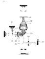
- FIG. 2 is a schematic diagram illustrating a fluorescent microscope according to the first embodiment of the present invention.
- FIG. 3 is a schematic diagram illustrating a principle of acquiring an image of a survey object with a first optical module of the fluorescent microscope of FIG. 2 .
- FIG. 4 is a schematic diagram illustrating a principle of acquiring an image of a survey object with a second optical module of the fluorescent microscope of FIG. 2 .
- FIG. 5 is a schematic diagram illustrating a principle of acquiring an image of a survey object with a third optical module of the fluorescent microscope of FIG. 2 .
- a survey object refers to an object-to-be-surveyed processed through a fluorescent sample, for example, a biochip.
- the fluorescent microscope 100 includes a first optical module 110 for acquiring an image of a survey object C by using a first light source 111, a second optical module 120 for acquiring an image of the survey object C by using a second light source 121, and a third optical module 130 provided to obtain a bright field image of the survey object C.
- the first optical module 110 is configured to acquire a fluorescent image of the survey object C by using the first light source 111, and includes a first light source 111 for supplying first excitation light L1, a first excitation filter 112 for selectively transmitting the first excitation light L1 supplied from the first light source 111, a first dichroic filter 113 for reflecting the first excitation light E1 having passed through the first excitation filter 112 toward the survey object C, an objective lens O for condensing the first excitation light E1 and transferring the condensed first excitation light E1 to the survey object C, a second dichroic filter 114 for reflecting first radiation light EM1 radiated from the survey object C by the first excitation light E1, a first radiation filter 115 for selectively transmitting the first radiation light EM1 reflected by the second dichroic filter 114, and a first image acquisition unit 116 for acquiring an image by using the first radiation light EM1 having passed through the first radiation filter 115 to be supplied.
- the first excitation light L1 supplied by the first light source 111, the first excitation light E1 having passed through the first excitation filter 112, and the first radiation light EM1 radiated from the survey object C are denoted by different reference symbols, considering the differences of the wavelengths of the light, and the items are the same in the exemplary embodiments of the present invention, and thus will not be repeatedly described.
- the first light source 111 is configured to supply the first excitation light L1 having a first wavelength W1, and in the present embodiment, a blue solid state fluorescence light source, in particular, a light emitting diode (LED) is used.
- the first light source 111 that is, an LED has a long life span as compared with a general mercury or Xenon arc type lamp, reducing the frequency of maintenance operations for replacing the first light source 111, deteriorates an amount of light less in proportion to a lighting time, allowing the first image acquisition unit 116 to obtain a stable image of the survey object C, emits a small amount of heat, preventing thermal deformation of the survey object C, and has a small-sized LED, miniaturizing the fluorescent microscope 100.
- a general mercury lamp may be used as the first light source 111 or a solid state fluorescence light source other than an LED may be used.
- the first excitation filter 112 is configured to selectively transmit the first excitation light L1 supplied from the first light source 111, and the first dichroic filter 113 is provided adjacent to the first excitation filter 112 to reflect the first excitation light E1 transferred from the first excitation filter 112 toward the survey object C.
- a dichroic filter functions to reflect light having a short wavelength and pass light having a long wavelength
- the first dichroic filter 113 of the present embodiment reflects the first excitation light E1 toward the survey object C or passes the first radiation light EM1 having a wavelength longer than that of the first excitation light E1 radiated from the survey object C as it is, allowing the first image acquisition unit 116 to acquire an image of the survey object C.
- the objective lens O is configured to condense the first excitation light E1 reflected by the first dichroic filter 113 and transfer the condensed first excitation light E1 to the survey object C.
- the first excitation light E1 reflected by the first dichroic filter 113 is condensed by the objective lens O and then is irradiated to the survey object to convert energy of the survey object C into a temporarily excited state, and the survey object C emits the absorbed energy again and returns to a stable state while emitting fluorescent light.
- first radiation light EM1 the fluorescent light generated from the survey object C by the first excitation light E1 is referred to as first radiation light EM1.
- the first radiation light E1 has a wavelength slightly displaced toward the red as compared with the first excitation light E1, and the change is called a stokes shift. That is, the first radiation light EM1 has a wavelength slightly longer than the first excitation light E1 according to the stokes shift, and the survey object C provided with the first excitation light E1 by the first light source 111, that is, a blue LED as in the present embodiment radiates light having a wavelength longer than that of blue light, for example, the first radiation light EM1 of a green color.
- the first radiation light EM1 radiated from the survey object C is reflected by the second dichroic filter 114 after passing through the objective lens O and the first dichroic filter 113 so that a path thereof is changed toward the first image acquisition unit 116.
- the first dichroic filter 113 functions to reflect the first excitation light E1 having a wavelength shorter than that of the first radiation light EM1 toward the survey object C but pass the first radiation light EM1 having a wavelength longer than that of the first excitation light E1 as it is.
- the second dichroic filter 114 functions to reflect the first radiation light EM1 radiated from the survey object C toward the first image acquisition unit 116, and the first radiation filter 115 is provided between the second dichroic filter 114 and the first image acquisition unit 116 to selectively transmit the first radiation light EM1 reflected by the second dichroic filter 114 and then transfer the first radiation light EM1 to the first image acquisition unit 116.
- the first radiation filter 115 removes such optical noise and transfers only the first radiation light EM1 having a desired wavelength to the first image acquisition unit 116 to help the first acquisition unit 116 to obtain a clear image.
- the first image acquisition unit 116 is configured to visually realize an image of the survey object C through the first radiation light EM1 having passed through the first radiation filter 115 to be provided.
- the first image acquisition unit 116 of the present embodiment is a charge-coupled device (CCD) image sensor or a complementary metal oxide semiconductor (CMOS) image sensor.
- CCD charge-coupled device
- CMOS complementary metal oxide semiconductor
- the CCD image sensor refers to an image sensor of the type in which after a CCD is exposed to light, information is copied to readout registers one by one from the lowermost row to read out charges stored in photosites, and the copied values are converted into numbers through an amplifier and an analogue-to-digital converter again, so that the registers are sequentially read out from the lowermost row to the uppermost row.
- CMOS image sensor refers to a solid state image pickup device which uses a photo diode like the CCD image sensor but uses a complimentary metal oxide semiconductor, which is manufactured and reads out signals in different ways.
- the first image acquisition unit 116 of the present embodiment may use any one of a CCD image sensor and a CMOS image sensor, but preferably uses a CMOS image sensor, considering improvement of integration, power consumptions and the like. Meanwhile, since it may be more preferable to use a CCD image sensor, considering a noise level, noise processing, and an image quality, a suitable image sensor needs to be adopted, considering a required specification of the fluorescent microscope 100.
- the first image acquisition unit 116 may obtain a green fluorescent protein (GFP) image of the survey object C by using the first light source 111.
- GFP green fluorescent protein
- a second optical module 120 is configured to acquire an image of a survey object C by using a second light source 121, and includes a second light source 121 for supplying second excitation light L2, a second excitation filter 122 for selectively transmitting the second excitation light L2 supplied from the second light source 121, a second radiation filter 123 for selectively transmitting the second radiation light EM2 having passed through the second excitation filter 122 and irradiated to the survey object C to be radiated, and a second image acquisition unit 124 for acquiring an image by using the second radiation light EM2 having passed through the second radiation filter 123 to be supplied.
- the second light source 121 is configured to supply the second excitation light L2 having a second wavelength W2, and is a green LED in the present embodiment.
- the second light source 121 may be a general mercury lamp.
- the second light source 121 is a red LED when the first light source 111 is a greed LED (the items are the same in the second and third embodiments).
- the second excitation filter 122 is configured to selectively transmit the second excitation light L2 supplied from the second light source 121.
- the second excitation light E2 having passed through the second excitation filter 122 to be transferred to the survey object C converts energy of the survey object C into a temporarily excited state, and the survey object C emits the absorbed energy again and returns to a stable state while emitting fluorescent light.
- the fluorescent light generated from the survey object C by the second excitation light E2 is referred to as second radiation light EM2.
- the second radiation light E2 has a wavelength slightly longer than the second excitation light E2 according to the stokes shift, and the survey object C provided with the second excitation light E2 by the second light source 121, that is, a green LED as in the present embodiment radiates light having a wavelength longer than that of green light, for example, the second radiation light EM2 of a red color.
- the second radiation light EM2 radiated from the survey object C passes through the objective lens O, the first dichroic filter 113, and the second dichroic filter 114, only the second radiation light EM2 from which optical noise is removed by the second radiation filter 123 is transferred to the second image acquisition unit 124.
- the second image acquisition unit 124 is a CCD image sensor or a CMOS image sensor, and acquires a red fluorescent protein (PFP) image of the survey object C through the second radiation light EM2 having passed through the second radiation filter 123 to be transferred.
- PFP red fluorescent protein
- the first image acquisition unit 116 and the second image acquisition unit 124 of the present embodiment can adjust exposure time and intensity of fluorescent light in response to the GFP image or RFP image to be surveyed.
- a fluorescent microscope includes only one survey part corresponding to the image acquisition unit 115 or 124 of the present embodiment, and should continuously adjust exposure time of a fluorescent image or intensity of fluorescent light to survey an RFP image after surveying a GFP image or survey a GFP image after surveying an RFP image.
- the fluorescent microscope according to the related art surveys a signal with one surveying part and thus various kinds of fluorescent light are sequentially viewed while individual conditions are continuously adjusted in the form of a turret or a revolver
- the fluorescent microscope 100 of the present embodiment includes the first image acquisition unit 116 and the second image acquisition unit 124 which can be adjusted independently, and thus an image can be continuously surveyed while a survey condition of a GFP image or a survey condition of an RFP image is individually adjusted.
- the items are the same in the other embodiment of the present invention, and a description thereof will not be repeated.
- the first. image acquisition unit 116 may obtain a bright field image of the survey object C through the second excitation light E2. That is, the second image acquisition unit 124 obtains an RFP image with the second light source 121, and the first image acquisition unit 116 obtains a bright field image.
- the second light source 121 supplies the second excitation light L2 in a direction parallel to the survey object C, a configuration for converting the second excitation light L2 to the survey object C is necessary, and this a third dichroic filter 125 in charge of such a role is additionally provided.
- the third optical module 130 is configured to obtain a bright field image of a survey object C by using a third light source 131, and includes a third light source 131 for supplying third excitation light L3, and a fourth dichroic filter 132 disposed in a direction perpendicular to a disposition direction of the third dichroic filter 125.
- the third light source 131 is a white and irradiates white light to the survey object C.
- the white light irradiated to the survey object C moves forward to the second image acquisition unit 124 as it is, and a surveyor can survey a bright field image of the survey object C through the second image acquisition unit 124.
- the bright field image acquired by the third light source is the same as that of a general optical microscope, and will not be described in detail.
- the fourth dichroic filter 132 is disposed in a direction perpendicular to a disposition direction of the third dichroic filter 125 so that a brightness of the bright field image acquired by the second image acquisition unit 124 can be uniformly adjusted.
- the brightness of the bright field image acquired through the second image acquisition unit 124 may not be uniform if only the third dichroic filter 125 is used, so the brightness of the bright field image acquired by the second acquisition unit 124 may be adjusted uniformly by disposing a pair of dichroic filters 125 and 132 such that the dichroic filters 125 and 132 are perpendicular to each other.
- the fluorescent microscope 100 of the present embodiment is devised to obtain a bright field image even through the second light source 120, and thus the third module 130 may be omitted if necessary.
- the fluorescent microscope 100 of the present invention includes the first image acquisition unit 116 and the second image acquisition unit 124, and thus simply and promptly surveys a plurality of fluorescent images without a mechanical movement.
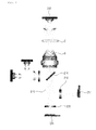
- FIG. 6 is a schematic diagram illustrating a fluorescent microscope according to the second embodiment of the present invention.
- FIG. 7 is a schematic diagram illustrating a principle of acquiring an image of a survey object with a first optical module of the fluorescent microscope of FIG. 6 .
- FIG. 8 is a schematic diagram illustrating a principle of acquiring an image of a survey object with a second optical module of the fluorescent microscope of FIG. 6 .
- FIG. 9 is a schematic diagram illustrating a principle of acquiring an image of a survey object by using a third optical light source of the fluorescent microscope of FIG. 6 .
- the fluorescent microscope 200 includes a first optical module 210 for acquiring an image of a survey object C by using a first light source 211, a second optical module 220 for acquiring an image of the survey object C by using a second light source 221, and a third optical module 230 provided to obtain a bright field image of the survey object C.
- the first optical module 210 is configured to acquire a fluorescent image of the survey object C by using the first light source 211, and includes a first light source 211 for supplying first excitation light L1 having a first wavelength W1, a first dichroic filter 212 for reflecting the first excitation light L1 supplied from the first light source 211, an excitation filter 213 for selectively transmitting the first excitation light L1 supplied from the first dichroic filter 212, a second dichroic filter 214 for reflecting the first excitation light E1 having passed through the first excitation filter 213 toward the survey object C, an objective lens O for condensing the first excitation light L1 reflected by the second dichroic filter 214 and transferring the condensed first excitation light L1 to the survey object C, a third dichroic filter 215 for reflecting first radiation light EM1 radiated from the survey object C, a first radiation filter 216 for selectively transmitting the first radiation light EM1 reflected by the third dichroic filter 215, and a first image acquisition unit 217
- a second optical module 220 is configured to acquire a fluorescent image of a survey object C by using a second light source 221, and includes a second light source 221 for supplying second excitation light L2 having a second wavelength W2, a second radiation filter 222 for selectively transmitting the second radiation light EM2 having a wavelength substantially the same as that of the second radiation light EM2 having passed through the excitation filter 213 to be reflected by the second dichroic filter 214 and having passed through the objective lens O and irradiated to the survey object C to be radiated, and a second image acquisition unit 223 for acquiring an image by using the second radiation light EM2.
- the items regarding the first light source 211, the third dichroic filter 215, the first radiation filter 216, the first image acquisition unit 217, the second light source 221, the second radiation filter 222, the second image acquisition unit 223, and the third light source 230 are substantially the same as the items regarding the first light source 111, the second dichronic filter 114, the first radiation filter 115, the first image acquisition unit 116, the second light source 121, the second radiation filter 123, the second image acquisition unit 124, and the third light source of the above-described first embodiment, respectively, and thus a repeated description will be omitted.
- the first light source 211 and the second light source 221 are disposed adjacent to each other in one module such that the first excitation light L1 and the second excitation light L2 are supplied in directions crossing each other, and the third light source 230 is provided separately from the first light source 211 and the second light source 221.
- the first light source 211 and the second light source 221 are sequentially adjusted, whereas when a bright field image of the survey object C is to be obtained, only the third light source 230 may be used to simply obtain the bright field image.
- the first dichroic filter 212 is provided adjacent to the first light source 211 to reflect the first excitation light L1 supplied from the first light source 211 toward the excitation filter 213, and the excitation filter 213 selectively transmits the first excitation light L1 reflected by the first dichroic filter 212.
- the excitation filter 213 is a dual band pass filter to pass only two kinds of light having different wavelengths. That is, the excitation filter 213 is provided to transmit both of the first excitation light L1 of the first light source 211 providing blue light and the second excitation light L2 of the second light source 221 providing green light.
- the second dichroic filter 214 of the present invention is a dual band pass filter to pass both of the first radiation light EM1 which is green light radiated from the survey object C by the first light source 211 and the second radiation light EM2 which is red light radiated from the survey object C by the second light source 221.
- a process of acquiring a fluorescent image or a bright field image of a survey object C by using the fluorescent microscope 200 of the present embodiment is as follows.
- the surveyor turns on the first light source 211 so that blue light is irradiated from the first light source 211.
- the first excitation light L1 supplied from the first light source 211 passes through the excitation filter 213, and the first excitation light E1 having passed through the excitation filter 213 is reflected by the second dichroic filter 214 and condensed through the objective lens O, and then is irradiated to the survey object C.
- the first radiation light EM1 which is green light is radiated from the survey object C having received the first excitation light E1 is radiated, and the first radiation light EM1 passes through the objective lens O and the second dichroic filter 214 and is reflected by the third dichroic filter 215, and a fluorescent image (GFP) is obtained through the first image acquisition unit 217 after optical noise is removed by the first radiation filter 216.
- GFP fluorescent image
- the surveyor turns off the first light source 211 and turns on the second light source 221 to irradiate green light from the second light source 221.
- the second excitation light L2 supplied from the second light source 221 is reflected toward the survey object C by the second dichroic filter 214, and after the second radiation light EM2 emitting from the survey object C passes through the objective lens O, the second dichroic filter 214, and the third dichroic filter 215, a fluorescent image (RFP) is obtained through the second image acquisition unit 223 after optical noise is removed by the second radiation filter 222.
- RFP fluorescent image
- the surveyor turns off the second light source 221 and turns on the third light source 230 to irradiate white light from the third light source 230.
- the white light supplied from the third light source 230 passes the survey object C, the objective lens O, and the second dichroic filter 214 as it is, some of the white light is reflected toward the first image acquisition unit 217 by the third dichroic filter 215, the remaining white light passes through the third dichroic filter 215 as it is and proceeds to the second image acquisition unit 223.
- the surveyor surveys a bright field image of the survey object C through the first image acquisition unit 217 and the second image acquisition unit 223.
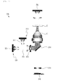
- FIG. 10 is a schematic diagram illustrating a fluorescent microscope according to the third embodiment of the present invention.
- FIG. 11 is a schematic diagram illustrating a principle of acquiring an image of a survey object with a first optical module of the fluorescent microscope of FIG. 10 .
- FIG. 12 is a schematic diagram illustrating a principle of acquiring an image of a survey object with a second optical module of the fluorescent microscope of FIG. 10 .
- FIG. 13 is a schematic diagram illustrating a principle of acquiring an image of a survey object by using a third optical light source of the fluorescent microscope of FIG. 10 .
- the fluorescent microscope 300 includes a first optical module 310 for acquiring an image of a survey object C by using a first light source 311, a second optical module 320 for acquiring an image of the survey object C by using a second light source 321, and a third light source 330 provided to obtain a bright field image of the survey object C.
- the first optical module 310 is configured to acquire a fluorescent image of the survey object C by using the first light source 311, and includes a first light source 311 for supplying first excitation light L1 having a first wavelength W1, a first dichroic filter 312 for reflecting the first excitation light L1 supplied from the first light source 311, an excitation filter 313 for selectively transmitting the first excitation light L1 reflected by the first dichroic filter 312, a second dichroic filter 314 for reflecting the first excitation light E1 having passed through the excitation filter 313 toward the survey object C, an objective lens O for condensing the first excitation light L1 reflected by the second dichroic filter 314 and transferring the condensed first excitation light L1 to the survey object C, a radiation filter 315 for selectively transmitting the first radiation light EM1 radiated from the survey object C, a and an image acquisition unit 316 for acquiring an image of the survey object by using the first radiation light EM1 having passed through the first radiation filter 315 to be supplied.
- a second optical module 320 is configured to acquire an image of a survey object C by using a second light source 321, and includes a second light source 321 for supplying second excitation light L2 having a second wavelength W2, and a third light source 330 is provided to obtain a bright field image of the survey object C.
- the items regarding the first light source 311, the first dichroic filter 312, the excitation filter 313, the second dichroic filter 314, the image acquisition unit 316, the second light source 321, and the third light source 330 are substantially the same as the items regarding the first light source 211, the first dichroic filter 212, the excitation filter 213, the second dichroic filter 214, the first image acquisition unit 217, the second light source 221, and the third light source 230 of the above-described second embodiment, respectively, and thus a repeated description thereof will be omitted.
- the radiation filter 315 is provided adjacent to the image acquisition unit 316 to selectively transmit the first radiation light EM1 and the second radiation light EM2.
- a dual band pass filter is provided as the radiation filter 315 of the present invention to remove optical noise contained in the first radiation light EM1 which is green light and the second radiation light EM2 which is red light while passing both the first radiation light EM1 and the second radiation light EM2.
- one dual band pass filter is provided as the radiation filter 315 to obtain both the fluorescent images (GFP and RFP) of the survey object C while removing the optical noise contained in the first radiation light EM1 and the second radiation light EM2.
- the other items regarding a method of using the fluorescent microscope 300 of the present embodiment are the same as the items regarding the method of using the fluorescent microscope 200 of the second embodiment, and a repeated description thereof will be omitted.
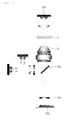
- FIG. 14 is a schematic diagram illustrating a fluorescent microscope according to the fourth embodiment of the present invention.
- FIG. 15 is a schematic diagram of a light source of the fluorescent microscope of FIG. 14 when viewed from the top.
- the fluorescent microscope 400 includes a plurality of light sources 411, 412, 413, and 414 provided to irradiate excitation light having different wavelengths to a survey object C, respectively, a bright field light source 415 provided to obtain a bright field image of the survey object C, a plurality of dichroic filters 421, 422, and 423 provided to reflect only light having short wavelengths of the light provided from the light sources 411, 412, 413, and 414, a plurality of image acquisition units 431, 432, 433, and 434 provided to obtain a fluorescent image of the survey object C by using the light reflected from the dichroic filters 421, 422, and 423, a plurality of excitation filters 441 and 442 provided between the light sources 411, 412, 413, and 414 and the survey object C, a plurality of radiation filters 451, 452, 453, and 454 provided between the dichroic filters 421, 422, and 423 and the image acquisition units 431, 432
- the light sources 411, 412, 413, and 414 are provided above the survey object C such that excitation light having different wavelengths is irradiated to the survey object C.
- the light sources 411, 412, 413, and 414 of the present embodiment are realized by LEDs spaced apart from each other by a predetermined interval to inclinedly irradiate excitation light of R (red), G (green), B (blue), and Y (yellow) colors.
- the bright field light source 415 is realized by white LEDs provided at central portions of the light sources 411, 412, 413, and 414 to obtain a bright field image of the survey object C in the same way as those of the above-described first to third embodiments.
- the surveyor desires to obtain a fluorescent image such as a GFP or an RFP of the survey object C, he or she selectively turns on the corresponding light sources 411, 412, 413, and 414, whereas when the surveyor desires to obtain a bright field image of the survey object C, he or she selectively turns off the light sources 411, 412, 413, and 414 and turns on the bright field light source 415.
- the dichroic filters 421, 422, and 423 are configured to reflect the radiation light radiated from the survey object C through the light supplied from the light sources 411, 412, 413, and 414 to the image acquisition units 431, 432, 433, and 434, respectively.
- the dichroic filter corresponding to the light source 414 provided in the red LED is omitted in the drawings.
- the dichroic filters 421, 422, and 423 of the present embodiment are provided to adjust optical paths of light sources like in all the other embodiments.
- the dichroic filters 421, 422, and 423 are disposed to be spaced apart from each other by a predetermined interval such that a dichroic filter reflecting radiation light having a short wavelength is closer to the survey object C than a dichroic filter reflecting radiation light having a relatively long wavelength. That is, the survey object C radiates green radiation light due to the light source 413 supplying blue light, and the dichroic filter 421 reflecting the green radiation light is located to be closest to the survey object C.
- a plurality of image acquisition units 431, 432, 433, and 434 are disposed to be spaced apart from each other such that a fluorescent image of the survey object C can be obtained through the radiation light reflected from the dichroic filters 421, 422, and 423, respectively.
- the image acquisition units 431, 432, 433, and 434 of the present embodiment are substantially the same as the first image acquisition unit 116 or the second image acquisition unit 124 of the above-described first embodiment, and a repeated description thereof will be omitted.
- the excitation filters 441 and 442 are provided between the light sources 411, 412, 413, and 414 and the survey object C, respectively to selectively transmit the excitation light supplied from the light sources 411, 412, 413, and 414, and the radiation filters 451, 452, 453, and 454 are provided between the 421, 422, and 423 and the image acquisition units 431, 432, 433, and 434 to remove optical noise of the radiation light radiated from the survey object C.
- the items regarding the excitation filters 441 and 442 and the radiation filters 451, 452, 453, and 454 can be seen with reference to the above-described first to third embodiments, a detailed description thereof will be described in detail.
- the image processing unit has a kind of software configuration for adjusting the images acquired through the image acquisition units 431, 432, 433, and 434.
- the items regarding the image processing performed by the image processing unit (not illustrated) can be seen with reference to a method of surveying a fluorescent image according to another embodiment of the present invention which will be described below, a detailed description thereof will be omitted.
- a process of acquiring a fluorescent image of the survey object C by using the fluorescent microscope 400 of the present invention is as follows.
- a surveyor turns on the light source 413, that is, a blue LED to irradiate blue light from the light source 413.
- the first excitation light L1 supplied from the light source 413 is irradiated to the survey object C after passing through the excitation filter 443, and green radiation light is radiated from the survey object C to which the first excitation light L1 is irradiated and passes through the objective lens O.
- the image acquisition unit 431 can obtain a fluorescent image GFP of the survey object C by using the radiation light.
- the fluorescent microscope 400 of the present embodiment includes the image acquisition units 431, 432, 433, and 434 corresponding to the plurality of light sources 411, 412, 413, and 414, so a plurality of fluorescent images can be simply and promptly surveyed without a mechanical movement.
- FIG. 16 is a flowchart of a fluorescent image surveying method according to an embodiment of the present invention.
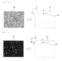
- FIGS. 17 to 21 are schematic diagrams illustrating a principle of the fluorescent image surveying method of FIG. 16 .
- the method of surveying a fluorescent image of the present embodiment may be applied to all the fluorescent microscopes of the above-described first to fourth embodiments, and the method of surveying a fluorescent image will be described below based on two images (a GFP and a bright field image) for clarity of description.
- the method of surveying a fluorescent image includes a step S11 of acquiring images of a survey object, respectively, a step S12 of extracting a first center area image forming a central portion of a first image, a step S13 of extracting a second center area image forming a central portion of a second image, a step S14 of comparing the first center area image and the second center area image to extract X and Y displacement values of the second center area image with respect to the first center area image, a step S15 of displacing the second image by using the X and Y displacement values to correct the second image, a step S16 of comparing an outskirt area of the first image and an outskirt area of the second image to extract a direction of a vector, and a step S17 of correcting the second image with reference to the first image, considering the direction of the vector.
- the step S11 of acquiring images of a survey object, respectively, is a step of acquiring a GFP image and a bright field image, respectively, by using the fluorescent microscopes 100, 200, 300, and 400 of the above-described first to fourth embodiments.
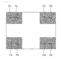
- the step S12 of extracting a first center area image forming a central portion of a first image is a step of extracting a central portion of a bright field image B1 acquired through the fluorescent microscopes 100, 200, 300, and 400, converting the extracted portion to a unicolor image, filter-processing the converted unicolor image, and selecting the filter-processed unicolor image as a first center area image C1
- the step S13 of extracting a second center area image forming a central portion of a second image is a step of extracting a central portion of a GFP image G2 acquired through the fluorescent microscopes 100, 200, 300, and 400, converting the extracted portion to a unicolor image, filter-processing the converted unicolor image, and selecting the filter-processed unicolor image as a second center area image C2.
- the central portions of the bright field image and the GFP image are extracted and selected as mutually comparable unicolor images.
- the step S14 of comparing the first center area image and the second center area image to extract X and Y displacement values of the second center area image with respect to the first center area image is a step of comparing the first center area image C1 and the second center area image C2 and catching a coordinate error value of the second center area image C2 with respect to the first center area image C1.
- a coordinate error value (X1-X2, Y1-Y2) of the pixel C21 of the second center area image C2 with respect to the pixel C11 of the first center area image C1 is extracted.
- the extracted coordinate error value (X1-X2, Y1-Y2) corresponds to X and Y displacement values which will be described below.
- step S14 through a process of not only comparing only one pixel C11 or C21 but also comparing a plurality of pixels forming the first center area image C1 and the second center area image C2 to find out an average error value, X and Y displacement values securing certainty are caught.
- the step S15 of displacing the second image by using the X and Y displacement values to correct the second image is a step of displacing the entire second image by using the X and Y displacement values found out in the former step S14 to match the GFP image with the bright field image. That is, in the present step S15, the pixels forming the GFP image are disposed at locations closest to the pixels forming the bright field image through adjustment of the entire image area of the GFP image.
- the step S16 of comparing an outskirt area of the first image and an outskirt area of the second image to extract a direction of a vector is a step of comparing the first image and the second image once again such that the locations of the pixels forming the second image corrected through the former step S15 may be closest to the locations of the pixels forming the first image, and a step S17 of correcting the second image with reference to the first image, considering the direction of the vector is a step of correcting the second image once again, considering the direction of the vector caught through the former step S16.
- the direction of the vector of the pixels contained in the outskirt areas is caught first by comparing the pixel values of the outskirt areas of the first image and the second image, and the second image is corrected through the steps S16 and S17.
- the step S12 of extracting a first center area image forming a central portion of a first image, the step S13 of extracting a second center area image forming a central portion of a second image, the step S14 of comparing the first center area image and the second center area image to extract X and Y displacement values of the second center area image with respect to the first center area image, and the step S15 of displacing the second image by using the X and Y displacement values to correct the second image may be omitted if necessary. That is, if necessary, a correction of the second image may be finished by comparing only the outskirt areas of the first image and the second image.
- the step S12 of extracting a first center area image forming a central portion of a first image, the step S13 of extracting a second center area image forming a central portion of a second image, the step S14 of comparing the first center area image and the second center area image to extract X and Y displacement values of the second center area image with respect to the first center area image, and the step S15 of displacing the second image by using the X and Y displacement values to correct the second image may be an independent image correcting method by themselves. That is, if necessary, a correction of the second image may be finished by comparing only the center areas of the first image and the second image.
- each of the above-described fluorescent microscopes 100, 200, 300, and 400 includes a plurality of image acquisition units (a kind of sensors), an alignment thereof cannot be accurately made due to mechanical tolerances and differences in precisions as the number of sensors increases, and accordingly, in order to solve the problem, in the method of surveying a fluorescent image of the present embodiment, a more precise fluorescent image can be obtained by supplementing images (a GFP image, an RFP image, and a bright field image) obtained through the fluorescent microscopes 100, 200, 300, and 400 in a software fashion.
- images a GFP image, an RFP image, and a bright field image
- a clearer and more accurate fluorescent image can be obtained by compensating an alignment of images (a GFP image, an RFP image, and a bright field image) obtained through the first to fourth embodiments in a software fashion.
Landscapes
- Physics & Mathematics (AREA)
- Chemical & Material Sciences (AREA)
- Analytical Chemistry (AREA)
- General Physics & Mathematics (AREA)
- Optics & Photonics (AREA)
- Spectroscopy & Molecular Physics (AREA)
- Health & Medical Sciences (AREA)
- Nuclear Medicine, Radiotherapy & Molecular Imaging (AREA)
- Life Sciences & Earth Sciences (AREA)
- Biochemistry (AREA)
- General Health & Medical Sciences (AREA)
- Immunology (AREA)
- Pathology (AREA)
- Microscoopes, Condenser (AREA)
- Investigating, Analyzing Materials By Fluorescence Or Luminescence (AREA)
Applications Claiming Priority (3)
| Application Number | Priority Date | Filing Date | Title |
|---|---|---|---|
| KR20100079932 | 2010-08-18 | ||
| PCT/KR2011/006084 WO2012023816A2 (fr) | 2010-08-18 | 2011-08-18 | Microscope à fluorescence pour observation d'image à fluorescence multiple, procédé d'observation d'image à fluorescence l'utilisant, et système d'observation d'image à fluorescence multiple |
| KR1020110082148A KR101287189B1 (ko) | 2010-08-18 | 2011-08-18 | 멀티 형광영상 관측용 형광현미경, 이를 이용한 형광영상의 관찰방법 및 멀티 형광영상 관측 시스템 |
Publications (2)
| Publication Number | Publication Date |
|---|---|
| EP2607889A2 true EP2607889A2 (fr) | 2013-06-26 |
| EP2607889A4 EP2607889A4 (fr) | 2016-11-09 |
Family
ID=46131433
Family Applications (1)
| Application Number | Title | Priority Date | Filing Date |
|---|---|---|---|
| EP11818416.7A Withdrawn EP2607889A4 (fr) | 2010-08-18 | 2011-08-18 | Microscope à fluorescence pour observation d'image à fluorescence multiple, procédé d'observation d'image à fluorescence l'utilisant, et système d'observation d'image à fluorescence multiple |
Country Status (4)
| Country | Link |
|---|---|
| US (1) | US9395527B2 (fr) |
| EP (1) | EP2607889A4 (fr) |
| KR (1) | KR101287189B1 (fr) |
| WO (1) | WO2012023816A2 (fr) |
Cited By (2)
| Publication number | Priority date | Publication date | Assignee | Title |
|---|---|---|---|---|
| CN111338067A (zh) * | 2020-03-27 | 2020-06-26 | 肯维捷斯(武汉)科技有限公司 | 一种微型荧光显微成像模块 |
| US12345868B2 (en) | 2020-11-25 | 2025-07-01 | Precipoint Gmbh | Digital microscope and method of operating a digital microscope |
Families Citing this family (21)
| Publication number | Priority date | Publication date | Assignee | Title |
|---|---|---|---|---|
| KR101675258B1 (ko) | 2013-02-20 | 2016-11-14 | 한국화학연구원 | 색선별 거울을 이용한 멀티발광 분광 분석방법 및 이를 이용한 발광 분광 분석장치 |
| KR101414248B1 (ko) * | 2013-03-27 | 2014-07-01 | (주)로고스바이오시스템스 | 형광 이미징 장치 |
| JP6252598B2 (ja) * | 2013-12-09 | 2017-12-27 | 株式会社ニコン | 光学装置、測定装置、測定方法、スクリーニング装置及びスクリーニング方法 |
| KR101450120B1 (ko) * | 2014-05-30 | 2014-10-13 | 리스광시스템(주) | 복수의 광원에 따른 이미지들을 동시에 획득하는 형광이미지 획득장치 |
| KR102412917B1 (ko) * | 2015-02-16 | 2022-06-27 | 한국전자통신연구원 | 현미경 |
| CN105486667A (zh) * | 2015-07-01 | 2016-04-13 | 上海睿钰生物科技有限公司 | 集成式荧光激发光源装置 |
| CN105629453A (zh) * | 2016-03-10 | 2016-06-01 | 德诺杰亿(北京)生物科技有限公司 | 荧光显微镜 |
| KR101951670B1 (ko) * | 2017-12-13 | 2019-02-25 | 한국과학기술원 | 미세액적 내 유전자 검출을 위한 광학장치 |
| JP2020143991A (ja) * | 2019-03-06 | 2020-09-10 | ソニー株式会社 | 微小粒子測定装置、微小粒子分取装置、微小粒子測定システム及び微小粒子分取システム |
| EP3928066B1 (fr) * | 2020-01-30 | 2022-11-30 | Outsight | Capteur à distance actif multispectral |
| WO2021169822A1 (fr) * | 2020-02-25 | 2021-09-02 | 上海交通大学 | Système d'imagerie approprié pour la détection multiple d'une biomolécule |
| KR20230124611A (ko) * | 2020-12-21 | 2023-08-25 | 소니그룹주식회사 | 화상 처리 장치 및 방법 |
| KR102545916B1 (ko) * | 2021-06-28 | 2023-06-21 | 주식회사 신코 | 마이크로플레이트 복합측정 장치 |
| KR102549929B1 (ko) * | 2021-08-05 | 2023-06-30 | 주식회사 메타플바이오 | 3차원 광 검출 장치 |
| CN114894113B (zh) * | 2022-04-27 | 2024-01-12 | 山东大学 | 基于荧光追踪样点的材料表层去除原位测量装置及方法 |
| CN119768677A (zh) | 2022-08-25 | 2025-04-04 | 易兹代亚科技股份有限公司 | 用于检测目标物质信号的图像获取设备及方法 |
| KR102825133B1 (ko) * | 2022-09-29 | 2025-06-26 | 재단법인대구경북과학기술원 | 매크로 형광 현미경 |
| EP4371472B1 (fr) * | 2022-11-15 | 2025-12-17 | Quest Photonic Devices B.V. | Dispositif de capture et de traitement d'image |
| KR102837876B1 (ko) * | 2022-11-29 | 2025-07-24 | 주식회사 스타노스 | 광학 현미경을 위한 자동 여기광 조절장치 및 자동 여기광 조절방법 |
| KR102674967B1 (ko) * | 2023-04-24 | 2024-06-13 | 주식회사 큐리오시스 | 다채널 형광 필터세트와 광원이 합쳐진 형광 필터블록 조립체 |
| EP4707893A1 (fr) * | 2023-04-24 | 2026-03-11 | Curiosis Inc. | Ensemble bloc de filtre et système optique l'utilisant |
Family Cites Families (15)
| Publication number | Priority date | Publication date | Assignee | Title |
|---|---|---|---|---|
| JP3796635B2 (ja) * | 1996-03-06 | 2006-07-12 | 富士写真フイルム株式会社 | 蛍光検出装置 |
| US6075643A (en) * | 1997-10-24 | 2000-06-13 | Olympus Optical Co., Ltd. | Reflected fluorescence microscope with multiple laser and excitation light sources |
| JP2000089124A (ja) * | 1998-09-14 | 2000-03-31 | Nikon Corp | 複合顕微鏡 |
| US6839454B1 (en) | 1999-09-30 | 2005-01-04 | Biodiscovery, Inc. | System and method for automatically identifying sub-grids in a microarray |
| US7187810B2 (en) * | 1999-12-15 | 2007-03-06 | Medispectra, Inc. | Methods and systems for correcting image misalignment |
| JP4185711B2 (ja) | 2002-06-10 | 2008-11-26 | 株式会社キーエンス | 複数の光源を備えた顕微鏡 |
| JP2005017282A (ja) | 2003-05-30 | 2005-01-20 | Olympus Corp | 受光ユニットおよびそれを含む測定装置 |
| WO2005083423A2 (fr) * | 2004-02-27 | 2005-09-09 | Board Of Regents, The University Of Texas System | Systeme et procede d'integration de fluides et de reactifs dans des cartouches autonomes contenant des detecteurs de membrane et de particules |
| JP2006220994A (ja) | 2005-02-10 | 2006-08-24 | Olympus Corp | 観察システム |
| US8078265B2 (en) * | 2006-07-11 | 2011-12-13 | The General Hospital Corporation | Systems and methods for generating fluorescent light images |
| EP2225600A2 (fr) * | 2007-09-05 | 2010-09-08 | Chroma Technology Corporation | Source de lumière |
| WO2009069675A1 (fr) * | 2007-11-27 | 2009-06-04 | Nikon Corporation | Microscope à fluorescence |
| US8054553B2 (en) * | 2008-06-12 | 2011-11-08 | Orbotech Ltd. | Illumination angle control using dichroic filters |
| JP4288323B1 (ja) * | 2008-09-13 | 2009-07-01 | 独立行政法人科学技術振興機構 | 顕微鏡装置及びそれを用いた蛍光観察方法 |
| JP5289884B2 (ja) | 2008-10-01 | 2013-09-11 | オリンパス株式会社 | レーザ顕微鏡装置 |
-
2011
- 2011-08-18 EP EP11818416.7A patent/EP2607889A4/fr not_active Withdrawn
- 2011-08-18 KR KR1020110082148A patent/KR101287189B1/ko active Active
- 2011-08-18 US US13/809,319 patent/US9395527B2/en active Active
- 2011-08-18 WO PCT/KR2011/006084 patent/WO2012023816A2/fr not_active Ceased
Cited By (2)
| Publication number | Priority date | Publication date | Assignee | Title |
|---|---|---|---|---|
| CN111338067A (zh) * | 2020-03-27 | 2020-06-26 | 肯维捷斯(武汉)科技有限公司 | 一种微型荧光显微成像模块 |
| US12345868B2 (en) | 2020-11-25 | 2025-07-01 | Precipoint Gmbh | Digital microscope and method of operating a digital microscope |
Also Published As
| Publication number | Publication date |
|---|---|
| WO2012023816A3 (fr) | 2012-05-10 |
| US20130201322A1 (en) | 2013-08-08 |
| WO2012023816A2 (fr) | 2012-02-23 |
| WO2012023816A9 (fr) | 2012-06-28 |
| US9395527B2 (en) | 2016-07-19 |
| KR20120024436A (ko) | 2012-03-14 |
| EP2607889A4 (fr) | 2016-11-09 |
| KR101287189B1 (ko) | 2013-07-17 |
Similar Documents
| Publication | Publication Date | Title |
|---|---|---|
| EP2607889A2 (fr) | Microscope à fluorescence pour observation d'image à fluorescence multiple, procédé d'observation d'image à fluorescence l'utilisant, et système d'observation d'image à fluorescence multiple | |
| US12468167B2 (en) | Systems and methods for illuminating and imaging objects | |
| US9377407B2 (en) | Reaction monitoring | |
| KR101260051B1 (ko) | 살아있는 세포에 대한 명시야 이미징 및 형광 이미징의 동시 수행이 가능한 세포 이미징 장치 및 방법 | |
| JP5806504B2 (ja) | 撮像装置およびこれを備える顕微鏡システム | |
| TWI574000B (zh) | 使用偏振光的檢查設備 | |
| CN107219207B (zh) | 一种ccd生物芯片荧光扫描仪的自动调焦方法 | |
| US20180372640A1 (en) | Imaging device and imaging method | |
| JP2014512548A5 (fr) | ||
| US20160061730A1 (en) | Fluorescence detection apparatus, test substance detection apparatus, and fluorescence detection method | |
| KR20210151815A (ko) | 교환 렌즈, 정보 처리 장치, 정보 처리 방법, 및 프로그램 | |
| US12345642B2 (en) | Optical system, and method of illuminating a sample plane | |
| JP2005091701A (ja) | 蛍光顕微鏡及び蛍光顕微鏡の励起光源制御方法 | |
| US20160054551A1 (en) | Method for imaging a sample by means of a microscope and microscope | |
| JP2007003323A (ja) | 撮影システム | |
| CN207908817U (zh) | 照明系统 | |
| US20190257753A1 (en) | Automatic fluorescence detection system | |
| US10627638B2 (en) | Devices, systems, and methods for illuminating objects | |
| JP2016225689A (ja) | 画像読取装置及び画像読取方法 | |
| US11977022B2 (en) | Optical inspection method, optical inspection device, and non-transitory computer-readable storage medium storing optical inspection program | |
| US12504324B2 (en) | Composite calibration plate | |
| JP2019176396A (ja) | 画像読取装置 | |
| WO2021117153A1 (fr) | Dispositif de détection de fluorescence et procédé de détection de fluorescence | |
| CN112730239A (zh) | 多色远心成像装置及其细胞分析系统 | |
| JP5119702B2 (ja) | 画像処理方法及び共焦点顕微鏡 |
Legal Events
| Date | Code | Title | Description |
|---|---|---|---|
| PUAI | Public reference made under article 153(3) epc to a published international application that has entered the european phase |
Free format text: ORIGINAL CODE: 0009012 |
|
| 17P | Request for examination filed |
Effective date: 20130318 |
|
| AK | Designated contracting states |
Kind code of ref document: A2 Designated state(s): AL AT BE BG CH CY CZ DE DK EE ES FI FR GB GR HR HU IE IS IT LI LT LU LV MC MK MT NL NO PL PT RO RS SE SI SK SM TR |
|
| AX | Request for extension of the european patent |
Extension state: BA ME |
|
| RIC1 | Information provided on ipc code assigned before grant |
Ipc: G02B 21/16 20060101ALI20160630BHEP Ipc: G01B 9/04 20060101ALI20160630BHEP Ipc: G01N 21/64 20060101AFI20160630BHEP Ipc: G02B 21/00 20060101ALI20160630BHEP |
|
| A4 | Supplementary search report drawn up and despatched |
Effective date: 20161011 |
|
| RIC1 | Information provided on ipc code assigned before grant |
Ipc: G01B 9/04 20060101ALI20161005BHEP Ipc: G01N 21/64 20060101AFI20161005BHEP Ipc: G02B 21/00 20060101ALI20161005BHEP Ipc: G02B 21/16 20060101ALI20161005BHEP |
|
| STAA | Information on the status of an ep patent application or granted ep patent |
Free format text: STATUS: REQUEST FOR EXAMINATION WAS MADE |
|
| STAA | Information on the status of an ep patent application or granted ep patent |
Free format text: STATUS: THE APPLICATION IS DEEMED TO BE WITHDRAWN |
|
| 18D | Application deemed to be withdrawn |
Effective date: 20170509 |