EP2609868B1 - Bereitstellung einer Benutzerschnittstelle in einem Ultraschallsystem - Google Patents
Bereitstellung einer Benutzerschnittstelle in einem Ultraschallsystem Download PDFInfo
- Publication number
- EP2609868B1 EP2609868B1 EP12199541.9A EP12199541A EP2609868B1 EP 2609868 B1 EP2609868 B1 EP 2609868B1 EP 12199541 A EP12199541 A EP 12199541A EP 2609868 B1 EP2609868 B1 EP 2609868B1
- Authority
- EP
- European Patent Office
- Prior art keywords
- ultrasound
- signals
- vector
- target object
- region
- Prior art date
- Legal status (The legal status is an assumption and is not a legal conclusion. Google has not performed a legal analysis and makes no representation as to the accuracy of the status listed.)
- Active
Links
Images






Classifications
-
- A—HUMAN NECESSITIES
- A61—MEDICAL OR VETERINARY SCIENCE; HYGIENE
- A61B—DIAGNOSIS; SURGERY; IDENTIFICATION
- A61B8/00—Diagnosis using ultrasonic, sonic or infrasonic waves
- A61B8/48—Diagnostic techniques
- A61B8/488—Diagnostic techniques involving Doppler signals
-
- A—HUMAN NECESSITIES
- A61—MEDICAL OR VETERINARY SCIENCE; HYGIENE
- A61B—DIAGNOSIS; SURGERY; IDENTIFICATION
- A61B8/00—Diagnosis using ultrasonic, sonic or infrasonic waves
- A61B8/06—Measuring blood flow
-
- A—HUMAN NECESSITIES
- A61—MEDICAL OR VETERINARY SCIENCE; HYGIENE
- A61B—DIAGNOSIS; SURGERY; IDENTIFICATION
- A61B8/00—Diagnosis using ultrasonic, sonic or infrasonic waves
- A61B8/08—Clinical applications
-
- A—HUMAN NECESSITIES
- A61—MEDICAL OR VETERINARY SCIENCE; HYGIENE
- A61B—DIAGNOSIS; SURGERY; IDENTIFICATION
- A61B8/00—Diagnosis using ultrasonic, sonic or infrasonic waves
- A61B8/13—Tomography
-
- A—HUMAN NECESSITIES
- A61—MEDICAL OR VETERINARY SCIENCE; HYGIENE
- A61B—DIAGNOSIS; SURGERY; IDENTIFICATION
- A61B8/00—Diagnosis using ultrasonic, sonic or infrasonic waves
- A61B8/13—Tomography
- A61B8/14—Echo-tomography
-
- A—HUMAN NECESSITIES
- A61—MEDICAL OR VETERINARY SCIENCE; HYGIENE
- A61B—DIAGNOSIS; SURGERY; IDENTIFICATION
- A61B8/00—Diagnosis using ultrasonic, sonic or infrasonic waves
- A61B8/46—Ultrasonic, sonic or infrasonic diagnostic devices with special arrangements for interfacing with the operator or the patient
- A61B8/461—Displaying means of special interest
- A61B8/463—Displaying means of special interest characterised by displaying multiple images or images and diagnostic data on one display
-
- A—HUMAN NECESSITIES
- A61—MEDICAL OR VETERINARY SCIENCE; HYGIENE
- A61B—DIAGNOSIS; SURGERY; IDENTIFICATION
- A61B8/00—Diagnosis using ultrasonic, sonic or infrasonic waves
- A61B8/46—Ultrasonic, sonic or infrasonic diagnostic devices with special arrangements for interfacing with the operator or the patient
- A61B8/461—Displaying means of special interest
- A61B8/465—Displaying means of special interest adapted to display user selection data, e.g. icons or menus
-
- A—HUMAN NECESSITIES
- A61—MEDICAL OR VETERINARY SCIENCE; HYGIENE
- A61B—DIAGNOSIS; SURGERY; IDENTIFICATION
- A61B8/00—Diagnosis using ultrasonic, sonic or infrasonic waves
- A61B8/46—Ultrasonic, sonic or infrasonic diagnostic devices with special arrangements for interfacing with the operator or the patient
- A61B8/467—Ultrasonic, sonic or infrasonic diagnostic devices with special arrangements for interfacing with the operator or the patient characterised by special input means
-
- A—HUMAN NECESSITIES
- A61—MEDICAL OR VETERINARY SCIENCE; HYGIENE
- A61B—DIAGNOSIS; SURGERY; IDENTIFICATION
- A61B8/00—Diagnosis using ultrasonic, sonic or infrasonic waves
- A61B8/46—Ultrasonic, sonic or infrasonic diagnostic devices with special arrangements for interfacing with the operator or the patient
- A61B8/467—Ultrasonic, sonic or infrasonic diagnostic devices with special arrangements for interfacing with the operator or the patient characterised by special input means
- A61B8/469—Ultrasonic, sonic or infrasonic diagnostic devices with special arrangements for interfacing with the operator or the patient characterised by special input means for selection of a region of interest
-
- G—PHYSICS
- G01—MEASURING; TESTING
- G01S—RADIO DIRECTION-FINDING; RADIO NAVIGATION; DETERMINING DISTANCE OR VELOCITY BY USE OF RADIO WAVES; LOCATING OR PRESENCE-DETECTING BY USE OF THE REFLECTION OR RERADIATION OF RADIO WAVES; ANALOGOUS ARRANGEMENTS USING OTHER WAVES
- G01S15/00—Systems using the reflection or reradiation of acoustic waves, e.g. sonar systems
- G01S15/88—Sonar systems specially adapted for specific applications
- G01S15/89—Sonar systems specially adapted for specific applications for mapping or imaging
- G01S15/8906—Short-range imaging systems; Acoustic microscope systems using pulse-echo techniques
- G01S15/8979—Combined Doppler and pulse-echo imaging systems
- G01S15/8984—Measuring the velocity vector
-
- G—PHYSICS
- G01—MEASURING; TESTING
- G01S—RADIO DIRECTION-FINDING; RADIO NAVIGATION; DETERMINING DISTANCE OR VELOCITY BY USE OF RADIO WAVES; LOCATING OR PRESENCE-DETECTING BY USE OF THE REFLECTION OR RERADIATION OF RADIO WAVES; ANALOGOUS ARRANGEMENTS USING OTHER WAVES
- G01S15/00—Systems using the reflection or reradiation of acoustic waves, e.g. sonar systems
- G01S15/88—Sonar systems specially adapted for specific applications
- G01S15/89—Sonar systems specially adapted for specific applications for mapping or imaging
- G01S15/8906—Short-range imaging systems; Acoustic microscope systems using pulse-echo techniques
- G01S15/8979—Combined Doppler and pulse-echo imaging systems
- G01S15/8988—Colour Doppler imaging
-
- G—PHYSICS
- G01—MEASURING; TESTING
- G01S—RADIO DIRECTION-FINDING; RADIO NAVIGATION; DETERMINING DISTANCE OR VELOCITY BY USE OF RADIO WAVES; LOCATING OR PRESENCE-DETECTING BY USE OF THE REFLECTION OR RERADIATION OF RADIO WAVES; ANALOGOUS ARRANGEMENTS USING OTHER WAVES
- G01S7/00—Details of systems according to groups G01S13/00, G01S15/00, G01S17/00
- G01S7/52—Details of systems according to groups G01S13/00, G01S15/00, G01S17/00 of systems according to group G01S15/00
- G01S7/52017—Details of systems according to groups G01S13/00, G01S15/00, G01S17/00 of systems according to group G01S15/00 particularly adapted to short-range imaging
- G01S7/52053—Display arrangements
- G01S7/52057—Cathode ray tube displays
- G01S7/5206—Two-dimensional coordinated display of distance and direction; B-scan display
- G01S7/52063—Sector scan display
-
- G—PHYSICS
- G01—MEASURING; TESTING
- G01S—RADIO DIRECTION-FINDING; RADIO NAVIGATION; DETERMINING DISTANCE OR VELOCITY BY USE OF RADIO WAVES; LOCATING OR PRESENCE-DETECTING BY USE OF THE REFLECTION OR RERADIATION OF RADIO WAVES; ANALOGOUS ARRANGEMENTS USING OTHER WAVES
- G01S7/00—Details of systems according to groups G01S13/00, G01S15/00, G01S17/00
- G01S7/52—Details of systems according to groups G01S13/00, G01S15/00, G01S17/00 of systems according to group G01S15/00
- G01S7/52017—Details of systems according to groups G01S13/00, G01S15/00, G01S17/00 of systems according to group G01S15/00 particularly adapted to short-range imaging
- G01S7/52053—Display arrangements
- G01S7/52057—Cathode ray tube displays
- G01S7/52071—Multicolour displays; using colour coding; Optimising colour or information content in displays, e.g. parametric imaging
-
- G—PHYSICS
- G01—MEASURING; TESTING
- G01S—RADIO DIRECTION-FINDING; RADIO NAVIGATION; DETERMINING DISTANCE OR VELOCITY BY USE OF RADIO WAVES; LOCATING OR PRESENCE-DETECTING BY USE OF THE REFLECTION OR RERADIATION OF RADIO WAVES; ANALOGOUS ARRANGEMENTS USING OTHER WAVES
- G01S7/00—Details of systems according to groups G01S13/00, G01S15/00, G01S17/00
- G01S7/52—Details of systems according to groups G01S13/00, G01S15/00, G01S17/00 of systems according to group G01S15/00
- G01S7/52017—Details of systems according to groups G01S13/00, G01S15/00, G01S17/00 of systems according to group G01S15/00 particularly adapted to short-range imaging
- G01S7/52053—Display arrangements
- G01S7/52057—Cathode ray tube displays
- G01S7/52073—Production of cursor lines, markers or indicia by electronic means
-
- G—PHYSICS
- G01—MEASURING; TESTING
- G01S—RADIO DIRECTION-FINDING; RADIO NAVIGATION; DETERMINING DISTANCE OR VELOCITY BY USE OF RADIO WAVES; LOCATING OR PRESENCE-DETECTING BY USE OF THE REFLECTION OR RERADIATION OF RADIO WAVES; ANALOGOUS ARRANGEMENTS USING OTHER WAVES
- G01S7/00—Details of systems according to groups G01S13/00, G01S15/00, G01S17/00
- G01S7/52—Details of systems according to groups G01S13/00, G01S15/00, G01S17/00 of systems according to group G01S15/00
- G01S7/52017—Details of systems according to groups G01S13/00, G01S15/00, G01S17/00 of systems according to group G01S15/00 particularly adapted to short-range imaging
- G01S7/52085—Details related to the ultrasound signal acquisition, e.g. scan sequences
- G01S7/52095—Details related to the ultrasound signal acquisition, e.g. scan sequences using multiline receive beamforming
-
- G—PHYSICS
- G06—COMPUTING OR CALCULATING; COUNTING
- G06T—IMAGE DATA PROCESSING OR GENERATION, IN GENERAL
- G06T5/00—Image enhancement or restoration
-
- G—PHYSICS
- G06—COMPUTING OR CALCULATING; COUNTING
- G06T—IMAGE DATA PROCESSING OR GENERATION, IN GENERAL
- G06T7/00—Image analysis
- G06T7/20—Analysis of motion
-
- G—PHYSICS
- G10—MUSICAL INSTRUMENTS; ACOUSTICS
- G10K—SOUND-PRODUCING DEVICES; METHODS OR DEVICES FOR PROTECTING AGAINST, OR FOR DAMPING, NOISE OR OTHER ACOUSTIC WAVES IN GENERAL; ACOUSTICS NOT OTHERWISE PROVIDED FOR
- G10K11/00—Methods or devices for transmitting, conducting or directing sound in general; Methods or devices for protecting against, or for damping, noise or other acoustic waves in general
- G10K11/18—Methods or devices for transmitting, conducting or directing sound
- G10K11/26—Sound-focusing or directing, e.g. scanning
- G10K11/34—Sound-focusing or directing, e.g. scanning using electrical steering of transducer arrays, e.g. beam steering
- G10K11/341—Circuits therefor
Definitions
- the present disclosure generally relates to ultrasound systems, and more particularly to providing a user interface for performing a filtering process upon a vector Doppler image in an ultrasound system.
- An ultrasound system has become an important and popular diagnostic tool since it has a wide range of applications. Specifically, due to its non-invasive and non-destructive nature, the ultrasound system has been extensively used in the medical profession. Modern high-performance ultrasound systems and techniques are commonly used to produce two-dimensional or three-dimensional ultrasound images of internal features of target objects (e.g., human organs).
- target objects e.g., human organs
- the ultrasound system provides ultrasound images of various modes including a brightness mode image representing reflection coefficients of ultrasound signals (i.e., ultrasound echo signals) reflected from a target object of a living body with a two-dimensional image, a Doppler mode image representing velocity of a moving target object with spectral Doppler by using a Doppler effect, a color Doppler mode image representing velocity of the moving target object with colors by using the Doppler effect, an elastic image representing mechanical characteristics of tissues before and after applying compression thereto and the like.
- a brightness mode image representing reflection coefficients of ultrasound signals (i.e., ultrasound echo signals) reflected from a target object of a living body with a two-dimensional image
- a Doppler mode image representing velocity of a moving target object with spectral Doppler by using a Doppler effect
- a color Doppler mode image representing velocity of the moving target object with colors by using the Doppler effect
- an elastic image representing mechanical characteristics of tissues before and after applying compression thereto and the like.
- the ultrasound system transmits the ultrasound signals to the living body and receives the ultrasound echo signals from the living body to form Doppler signals corresponding to a region of interest, which is set on the brightness mode image.
- the ultrasound system further forms the color Doppler mode image representing the velocity of the moving target object with colors based on the Doppler signals.
- the color Doppler image represents the motion of the target object (e.g., blood flow) with the colors.
- the color Doppler image is used to diagnose diseases of blood vessels, heart and the like.
- the target object e.g., blood flow
- the respective colors indicated by a motion value is a function of the velocity of the target object, which moves forward in a transmission direction of the ultrasound signals and moves backward in the transmission direction of the ultrasound signals.
- the true velocity vector, or a projection thereof onto a scan plane, for blood flowing at a location in a vessel is determined from multiple Doppler velocity components.
- the true velocity vector is displayed as an arrowlike directional marker on an image comprising the vessel.
- the true velocity magnitude and angle, and scalar blood flow characteristics derived therefrom, are plotted as a functions of time and/or position across the depiction of the blood vessel in the image.
- US 2003/013959 A1 discloses a graphical user interface for an ultrasound system.
- the ultrasound system has operational modes, and the graphical user interface has corresponding icons, tabs, and menu items Image and information fields.
- the user interface provides several types of graphical elements in a tool bar with intelligent behavior, such as being context sensitive and adaptive, called active objects, for example, tabs, menus, icons, windows of user interaction and data display, and an alphanumeric keyboard.
- US2009/030321 A1 , US 4,768,515 A and US2010/069757 A1 refer to ultrasound systems providing a user interface for performing a filtering process upon a vector Doppler image in an ultrasound system.
- an ultrasound system with the features of claim 1 and a method of providing a user interface with the features of claim 5 are provided. Accordingly, a vector Doppler method capable of obtaining the velocity and direction of the blood flow is used.
- a cross beam-based method of the vector Doppler method acquires velocity magnitude components from at least two different directions, and combine the velocity magnitude components to detect vector information having a two-dimensional or three-dimensional direction information and a magnitude information.
- an ultrasound system comprises the features of claim 1.
- an ultrasound imaging method comprising the method steps of claim 4.
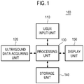
- an ultrasound system 100 in accordance with an illustrative embodiment is shown. As depicted therein, the ultrasound system 100 includes a user input unit 110.
- the user input unit 110 is configured to receive input information from a user.
- the input information includes first input information for setting a first region of interest ROI 1 on a brightness mode image BI, as shown in FIG. 2 .
- the first region of interest ROI 1 includes a color box for obtaining a Doppler mode image.
- the Doppler mode image includes a vector Doppler image corresponding to motion (i.e., velocity and direction) of a target object.
- the input information further includes second input information for setting at least one region for representing only the motion of target in a specific direction on the vector Doppler image.
- the reference numeral BV represents a blood vessel.
- the user input unit 110 includes a control panel, a track ball, a touch screen, a keyboard, a mouse and the like.
- the ultrasound system 100 further includes an ultrasound data acquiring unit 120.
- the ultrasound data acquiring unit 120 is configured to transmit ultrasound signals to a living body.
- the living body includes the target object (e.g., blood flow, blood vessel, heart, etc.).
- the ultrasound data acquiring unit 120 is further configured to receive ultrasound signals (i.e., ultrasound echo signals) from the living body to acquire ultrasound data corresponding to an ultrasound image.
- FIG. 3 is a block diagram showing an illustrative embodiment of the ultrasound data acquiring unit 120.
- the ultrasound data acquiring unit 120 includes an ultrasound probe 310.
- the ultrasound probe 310 includes a plurality of elements 311 ( see FIG. 4 ) for reciprocally converting between ultrasound signals and electrical signals.
- the ultrasound probe 310 is configured to transmit the ultrasound signals to the living body.
- the ultrasound signals transmitted from the ultrasound probe 310 are plane wave signals that the ultrasound signals are not focused at a focusing point, or focused signals that the ultrasound signals are focused at the focusing point. However, it should be noted herein that the ultrasound signals may not be limited thereto.
- the ultrasound probe 310 is further configured to receive the ultrasound echo signals from the living body to output electrical signals (hereinafter referred to as "reception signals").
- the reception signals are analog signals.
- the ultrasound probe 310 includes a convex probe, a linear probe and the like.
- the ultrasound data acquiring unit 120 further includes a transmitting section 320.
- the transmitting section 320 is configured to control the transmission of the ultrasound signals.
- the transmitting section 320 is also configured to generate electrical signals (hereinafter referred to as "transmission signals") in consideration of the elements 311.
- the transmitting section 320 is configured to generate transmission signals (hereinafter referred to as "brightness mode transmission signals”) for obtaining the brightness mode image BI in consideration of the elements 311.
- the ultrasound probe 310 is configured to convert the brightness mode transmission signals provided from the transmitting section 320 into the ultrasound signals, transmit the ultrasound signals to the living body, and receive the ultrasound echo signals from the living body to output reception signals (hereinafter referred to as “brightness mode reception signals").
- the transmitting section 320 is further configured to generate transmission signals (hereinafter referred to as "Doppler mode transmission signals”) corresponding to an ensemble number in consideration of the elements 311 and at least one transmission direction of the ultrasound signals (i.e., transmission beam).
- Doppler mode transmission signals transmission signals
- the ultrasound probe 310 is configured to convert the Doppler mode transmission signals provided from the transmitting section 320 into the ultrasound signals, transmit the ultrasound signals to the living body in the at least one transmission direction, and receive the ultrasound echo signals from the living body to output reception signals (hereinafter referred to as "Doppler mode reception signals").
- the ensemble number represents the number of transmitting and receiving the ultrasound signals to and from the living body.
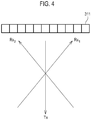
- the transmitting section 320 is configured to generate the Doppler mode transmission signals corresponding to the ensemble number in consideration of a transmission direction Tx and the elements 311, as shown in FIG. 4 .
- the transmission direction is one of a direction (i.e., 0 degree) perpendicular to a longitudinal direction of the elements 311 to a maximum steering direction of the transmission beam.
- the transmitting section 320 is configured to generate first Doppler mode transmission signals corresponding to the ensemble number in consideration of a first transmission direction Tx 1 and the elements 311, as shown in FIG. 5 .
- the ultrasound probe 310 is configured to convert the first Doppler mode transmission signals provided from the transmitting section 320 into the ultrasound signals, transmit the ultrasound signals to the living body in the first transmission direction Tx 1 , and receive the ultrasound echo signals from the living body to output first Doppler mode reception signals.
- the transmitting section 320 is further configured to generate second Doppler mode transmission signals corresponding to the ensemble number in consideration of a second transmission direction Tx 2 and the elements 311, as shown in FIG. 5 .
- the ultrasound probe 310 is configured to convert the second Doppler mode transmission signals provided from the transmitting section 320 into the ultrasound signals, transmit the ultrasound signals to the living body in the second transmission direction Tx 2 , and receive the ultrasound echo signals from the living body to output second Doppler mode reception signals.
- the reference numeral PRI represents a pulse repeat interval.
- the transmitting section 320 is configured to generate the brightness mode transmission signals for obtaining the brightness mode image BI in consideration of the elements 311.
- the ultrasound probe 310 is configured to convert the brightness mode transmission signals provided from the transmitting section 320 into the ultrasound signals, transmit the ultrasound signals to the living body, and receive the ultrasound echo signals from the living body to output the brightness mode reception signals.
- the transmitting section 320 is further configured to generate the Doppler mode transmission signals corresponding to the ensemble number in consideration of the at least one transmission direction and the elements 311.
- the ultrasound probe 310 is configured to convert the Doppler mode transmission signals provided from the transmitting section 320 into the ultrasound signals, transmit the ultrasound signals to the living body, and receive the ultrasound echo signals from the living body to output the Doppler mode reception signals.
- the ultrasound signals are transmitted in an interleaved transmission scheme. The interleaved transmission scheme will be described below in detail.
- the transmitting section 320 is configured to generate the first Doppler mode transmission signals in consideration of the first transmission direction Tx 1 and the elements 311, as shown in FIG. 6 .
- the ultrasound probe 310 is configured to convert the first Doppler mode transmission signals provided from the transmitting section 320 into the ultrasound signals, and transmit the ultrasound signals to the living body in the first transmission direction Tx 1 .
- the transmitting section 320 is further configured to generate the second Doppler mode transmission signals in consideration of the second transmission direction Tx 2 and the elements 311, as shown in FIG. 6 .
- the ultrasound probe 310 is configured to convert the second Doppler mode transmission signals provided from the transmitting section 320 into the ultrasound signals, and transmit the ultrasound signals to the living body in the second transmission direction Tx 2 .
- the ultrasound probe 310 is further configured to receive the ultrasound echo signals (i.e., ultrasound echo signals corresponding to first Doppler mode transmission signals) from the living body to output the first Doppler mode reception signals.
- the ultrasound probe 310 is further configured to receive the ultrasound echo signals (i.e., ultrasound echo signals corresponding to second Doppler mode transmission signals) from the living body to output the second Doppler mode reception signals.
- the transmitting section 320 is configured to generate the first Doppler mode transmission signals based on the pulse repeat interval, as shown in FIG. 6 .
- the ultrasound probe 310 is configured to convert the first Doppler mode transmission signals provided from the transmitting section 320 into the ultrasound signals, and transmit the ultrasound signals to the living body in the first transmission direction Tx 1 .
- the transmitting section 320 is further configured to generate the second Doppler mode transmission signals based on the pulse repeat interval, as shown in FIG. 6 .
- the ultrasound probe 310 is configured to convert the second Doppler mode transmission signals provided from the transmitting section 320 into the ultrasound signals, and transmit the ultrasound signals to the living body in the second transmission direction Tx 2 .
- the ultrasound probe 310 is further configured to receive the ultrasound echo signals (i.e., ultrasound echo signals corresponding to first Doppler mode transmission signals) from the living body to output the first Doppler mode reception signals.
- the ultrasound probe 310 is further configured to receive the ultrasound echo signals (i.e., ultrasound echo signals corresponding to second Doppler mode transmission signals) from the living body to output the second Doppler mode reception signals.
- the transmitting section 320 is configured to generate the first Doppler mode transmission signals and the second Doppler mode transmission signals corresponding to the ensemble number.
- the transmitting section 320 is configured to generate the brightness mode transmission signals for obtaining the brightness mode image BI in consideration of the elements 311.
- the ultrasound probe 310 is configured to convert the brightness mode transmission signals provided from the transmitting section 320 into the ultrasound signals, transmit the ultrasound signals to the living body, and receive the ultrasound echo signals from the living body to output the brightness mode reception signals.
- the transmitting section 320 is further configured to generate the Doppler mode transmission signals corresponding to the ensemble number in consideration of the at least one transmission direction and the elements 311.
- the ultrasound probe 310 is configured to convert the Doppler mode transmission signals provided from the transmitting section 320 into the ultrasound signals, transmit the ultrasound signals to the living body in the at least one transmission direction, and receive the ultrasound echo signals from the living body to output the Doppler mode reception signals.
- the ultrasound signals are transmitted according to the pulse repeat interval.
- the transmitting section 320 is configured to generate the first Doppler mode transmission signals in consideration of the first transmission direction Tx 1 and the elements 311 based on the pulse repeat interval, as shown in FIG. 7 .
- the ultrasound probe 310 is configured to convert the first Doppler mode transmission signals provided from the transmitting section 320 into the ultrasound signals, transmit the ultrasound signals to living body in the first transmission direction Tx 1 , and receive the ultrasound echo signals from the living body to output the first Doppler mode reception signals.
- the transmitting section 320 is further configured to generate the second Doppler mode transmission signals in consideration of the second transmission direction Tx 2 and the elements 311 based on the pulse repeat interval, as shown in FIG. 7 .
- the ultrasound probe 310 is configured to convert the second Doppler mode transmission signals provided from the transmitting section 320 into the ultrasound signals, transmit the ultrasound signals to the living body in the second transmission direction Tx 2 , and receive the ultrasound echo signals from the living body to output the second Doppler mode reception signals.
- the transmitting section 320 is configured to generate the first Doppler mode transmission signals and the second Doppler mode transmission signals corresponding to the ensemble number based on the pulse repeat interval.
- the ultrasound data acquiring unit 120 further includes a receiving section 330.
- the receiving section 330 is configured to perform an analog-digital conversion upon the reception signals provided from the ultrasound probe 310 to form sampling data.
- the receiving section 330 is further configured to perform a reception beam-forming upon the sampling data in consideration of the elements 311 to form reception-focused data. The reception beam-forming will be described below in detail.
- the receiving section 330 is configured to perform the analog-digital conversion upon the brightness mode reception signals provided from the ultrasound probe 310 to form sampling data (hereinafter referred to as “brightness mode sampling data").
- the receiving section 330 is further configured to perform the reception beam-forming upon the brightness mode sampling data to form reception-focused data (hereinafter referred to as “brightness mode reception-focused data").
- the receiving section 330 is further configured to perform the analog-digital conversion upon the Doppler mode reception signals provided from the ultrasound probe 310 to form sampling data (hereinafter referred to as "Doppler mode sampling data").
- the receiving section 330 is further configured to perform the reception beam-forming upon the Doppler mode sampling data to form reception-focused data (hereinafter referred to as "Doppler mode reception-focused data") corresponding to at least one reception direction of the ultrasound echo signals (i.e., reception beam).
- the receiving section 330 is configured to perform the analog-digital conversion upon the Doppler mode reception signals provided from the ultrasound probe 310 to form the Doppler mode sampling data.
- the receiving section 330 is further configured to perform the reception beam-forming upon the Doppler mode sampling data to form first Doppler mode reception-focused data corresponding to a first reception direction Rx 1 and second Doppler mode reception-focused data corresponding to a second reception direction Rx 2 , as shown in FIG. 4 .
- the receiving section 330 is configured to perform the analog-digital conversion upon the first Doppler mode reception signals provided from the ultrasound probe 310 to form first Doppler mode sampling data corresponding to the first transmission direction Tx 1 , as shown in FIG. 5 .
- the receiving section 330 is further configured to perform the reception beam-forming upon the first Doppler mode sampling data to form the first Doppler mode reception-focused data corresponding to the first reception direction Rx 1 .
- the receiving section 330 is also configured to perform the analog-digital conversion upon the second Doppler mode reception signals provided from the ultrasound probe 310 to form second Doppler mode sampling data corresponding to the second transmission direction Tx 2 , as shown in FIG. 5 .
- the receiving section 330 is further configured to perform the reception beam-forming upon the second Doppler mode sampling data to form the second Doppler mode reception-focused data corresponding to the second reception direction Rx 2 . If the reception direction is perpendicular to the elements 311 of the ultrasound probe 310, then a maximum aperture size is used.
- the receiving section 330 is configured to perform the analog-digital conversion upon the reception signals provided through a plurality of channels CH k , wherein 1 ⁇ k ⁇ N, from the ultrasound probe 310 to form sampling data S i,j , wherein the i and j are a positive integer, as shown in FIG. 8 .
- the sampling data S i,j are stored in a storage unit 140.
- the receiving section 330 is further configured to detect pixels corresponding to the sampling data based on positions of the elements 311 and positions (orientation) of pixels of the ultrasound image UI with respect to the elements 311.
- the receiving section 330 selects the pixels, which the respective sampling data are used as pixel data thereof, during the reception beam-forming based on the positions of the elements 311 and the orientation of the respective pixels of the ultrasound image UI with respect to the elements 311.
- the receiving section 330 is configured to cumulatively assign the sampling data corresponding to the selected pixels as the pixel data.
- the receiving section 330 is configured to set a curve (hereinafter referred to as "reception beam-forming curve") CV 6,3 for selecting pixels, which the sampling data S 6,3 are used as the pixel data thereof, during the reception beam-forming based on the positions of the elements 311 and the orientation of the respective pixels of the ultrasound image UI with respect to the elements 311, as shown in FIG. 9 .
- the receiving section 330 is further configured to detect the pixels P 3,1 , P 3,2 , P 4,2 , P 4,3 , P 4,4 , P 4,5 , P 4,6 , P 4,7 , P 4,8 , P 4,9 , ...
- the receiving section 330 selects the pixels P 3,1 , P 3,2 , P 4,2 , P 4,3 , P 4,4 , P 4,5 , P 4,6 , P 4,7 , P 4,8 , P 4,9 , ... P 3,N on which the reception beam-forming curve CV 6,3 passes among the pixels P a,b of the ultrasound image UI.
- the receiving section 330 is also configured to assign the sampling data S 6,3 to the selected pixels P 3,1 , P 3,2 , P 4,2 , P 4,3 , P 4,4 , P 4,5 , P 4,6 , P 4,7 , P 4,8 , P 4,9 , ... P 3,N , as shown in FIG. 10 .
- the receiving section 330 is configured to set a reception beam-forming curve CV 6,4 for selecting pixels, which the sampling data S 6,4 are used as the pixel data thereof, during the reception beam-forming based on the positions of the elements 311 and the orientation of the respective pixels of the ultrasound image UI with respect to the elements 311, as shown in FIG. 11 .
- the receiving section 330 is further configured to detect the pixels P 2,1 , P 3,1 , P 3,2 , P 4,2 , P 4,3 , P 4,4 , P S,4 , P 5,5 , P 5,6 , P 5,7 , P 5,8 , P 4,9 , P 5,9 , ...
- the receiving section 330 selects the pixels P 2,1 , P 3,1 , P 3,2 , P 4,2 , P 4,3 , P 4,4 , P 5,4 , P 5,5 , P 5,6 , P 5,7 , P 5,8 , P 4,9 , P 5,9 , ... P 4,N , P 3,N on which the reception beam-forming curve CV 6,4 passes among the pixels P a,b of the ultrasound image UI.
- the receiving section 330 is additionally configured to assign the sampling data S 6,4 to the selected pixels P 2,1 , P 3,1 , P 3,2 , P 4,2 , P 4,3 , P 4,4 , P 5,4 , P 5,5 , P 5,6 , P 5,7 , P 5,8 , P 4,9 , P 5,9 , ... P 4,N , P 3,N , as shown in FIG. 12 .
- the respective sampling data which are used as the pixel data, are cumulatively assigned to the pixels as the pixel data.
- the receiving section 330 is configured to perform the reception beam-forming (i.e., summing) upon the sampling data, which are cumulatively assigned to the respective pixels P a,b of the ultrasound image UI to form the reception-focused data.
- the receiving section 330 is configured to perform the analog-digital conversion upon the reception signals provided through the plurality of cannels CH k from the ultrasound probe 310 to form the sampling data S i,j , as shown in FIG. 8 .
- the sampling data S i,j are stored in the storage unit 140.
- the receiving section 330 is further configured to detect pixels corresponding to the sampling data based on the positions of the elements 311 and the positions (orientation) of the pixels of the ultrasound image UI with respect to the elements 311. That is, the receiving section 330 selects the pixels, which the respective sampling data are used as the pixel data thereof, during the reception beam-forming based on the positions of the elements 311 and the orientation of the respective pixels of the ultrasound image UI with respect to the elements 311.
- the receiving section 330 is configured to cumulatively assign the sampling data corresponding to the selected pixels as the pixel data.
- the receiving section 330 is further configured to determine pixels existing in the same column among the selected pixels.
- the receiving section 330 is also configured to set weights corresponding to the respective determined pixels.
- the receiving section 330 is additionally configured to apply the weights to the sampling data of the respective pixels.
- the receiving section 330 is configured to set the reception beam-forming curve CV 6,3 for selecting pixels, which the sampling data S 6,3 are used as the pixel data thereof, during the reception beam-forming based on the positions of the elements 311 and the orientation of the respective pixels of the ultrasound image UI with respect to the elements 311, as shown in FIG. 9 .
- the receiving section 330 is further configured to detect the pixels P 3,1 , P 3,2 , P 4,2 , P 4,3 , P 4,4 , P 4,5 , P 4,6 , P 4,7 , P 4,8 , P 4,9 , ...
- the receiving section 330 selects the pixels P 3,1 , P 3,2 P 4,2 , P 4,3 , P 4,4 , P 4,5 , P 4,6 , P 4,7 , P 4,8 , P 4,9 , ... P 3,N on which the reception beam-forming curve CV 6,3 passes among the pixels P a,b of the ultrasound image UI.
- the receiving section 330 is also configured to assign the sampling data S 6,3 to the selected pixels P 3,1 , P 3,2 , P 4,2 , P 4,3 , P 4,4 , P 4,5 , P 4,6 , P 4,7 , P 4,8 , P 4,9 , ... P 3,N as shown in FIG. 10 .
- the receiving section 330 is further configured to determine pixels P 3,2 and P 4,2 , which exist in the same column among the selected pixels P 3,1 , P 3,2 , P 4,2 , P 4,3 , P 4,4 , P 4,5 , P 4,6 , P 4,7 , P 4,8 , P 4,9 , ... P 3,N .
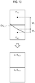
- the receiving section 330 is further configured to calculate a distance W 1 from a center of the determined pixel P 3,2 to the reception beam-forming curve CV 6,3 and a distance W 2 from a center of the determined pixel P 4,2 to the reception beam-forming curve CV 6,3 , as shown in FIG. 13 .
- the receiving section 330 is additionally configured to set a first weight ⁇ 1 corresponding to the pixel P 3,2 based on the distance W 1 and a second weight ⁇ 2 corresponding to the pixel P 4,2 based on the distance W 2 .
- the first weight ⁇ 1 and the second weight ⁇ 2 are set to be in proportional to or in inverse proportional to the calculated distances.
- the receiving section 330 is further configured to apply the first weight ⁇ 1 to the sampling data S 6,3 assigned to the pixel P 3,2 and to apply the second weight ⁇ 2 to the sampling data S 6,3 assigned to the pixel P 4,2 .
- the receiving section 330 is configured to perform the above process upon the remaining sampling data.
- the receiving section 330 is configured to perform the reception beam-forming upon the sampling data, which are cumulatively assigned to the respective pixels P a,b of the ultrasound image UI to form the reception-focused data.
- the receiving section 330 is configured to perform the analog-digital conversion upon the reception signals provided through the plurality of channels CH k from the ultrasound probe 310 to form the sampling data S i,j , as shown in FIG. 8 .
- the sampling data S i,j are stored in the storage unit 140.
- the receiving section 330 is further configured to set a sampling data set based on the sampling data S i,j . That is, the receiving section 330 sets the sampling data set for selecting pixels, which the sampling data S i,j are used as the pixel data thereof, during the reception beam-forming.
- the receiving section 330 is configured to set the sampling data S 1,1 S 1,4 , ... S 1,t , S 2,1 , S 2,4 , ... S 2,t , ... S p,t as the sampling data set (denoted by a box) for selecting the pixels, which the sampling data S i,j are used as the pixel data thereof, during the reception beam-forming, as shown in FIG. 14 .
- the receiving section 330 is further configured to detect the pixels corresponding to the respective sampling data of the sampling data set based on the positions of the elements 311 and the positions (orientation) of the respective pixels of the ultrasound image UI with respect to the elements 311. That is, the receiving section 330 selects the pixels, which the respective sampling data of the sampling data set are used as the pixel data thereof, during the reception beam-forming based on the positions of the elements 311 and the orientation of the respective pixels of the ultrasound image UI with respect to the elements 311.
- the receiving section 330 is further configured to cumulatively assign the sampling data to the selected pixels in the same manner as the above embodiments.
- the receiving section 330 is also configured to perform the reception beam-forming upon the sampling data, which are cumulatively assigned to the respective pixels of the ultrasound image UI to form the reception-focused data.
- the receiving section 330 is configured to perform down-sampling upon the reception signals provided through the plurality of channels CH k from the ultrasound probe 310 to form down-sampled data. As described above, the receiving section 330 is further configured to detect the pixels corresponding to the respective sampling data based on the positions of the elements 311 and the positions (orientation) of the respective pixels of the ultrasound image UI with respect to the elements 311. That is, the receiving section 330 selects the pixels, which the respective sampling data are used as the pixel data thereof, during the reception beam-forming based on the positions of the elements 311 and the orientation of the pixels of the ultrasound image UI with respect to the elements 311.
- the receiving section 330 is further configured to cumulatively assign the respective sampling data to the selected pixels in the same manner as the above embodiments.
- the receiving section 330 is further configured to perform the reception beam-forming upon the sampling data, which are cumulatively assigned to the respective pixels of the ultrasound image UI to form the reception-focused data.
- reception beam-forming may not be limited thereto.
- the ultrasound data acquiring unit 120 further includes an ultrasound data forming section 340.
- the ultrasound data forming section 340 is configured to form the ultrasound data corresponding to the ultrasound image based on the reception-focused data provided from the receiving section 330.
- the ultrasound data forming section 340 is further configured to perform a signal process (e.g., gain control, etc) upon the reception-focused data.
- a signal process e.g., gain control, etc
- the ultrasound data forming section 340 is configured to form ultrasound data (hereinafter referred to as "brightness mode ultrasound data") corresponding to the brightness mode image based on the brightness mode reception-focused data provided from the receiving section 330.
- the brightness mode ultrasound data include radio frequency data.
- the ultrasound data forming section 340 is further configured to form ultrasound data (hereinafter referred to as "Doppler mode ultrasound data") corresponding to the first region of interest ROI 1 based on the Doppler mode reception-focused data provided from the receiving section 330.
- the Doppler mode ultrasound data include in-phase/quadrature data. However, it should be noted herein that the Doppler mode ultrasound data may not be limited thereto.
- the ultrasound data forming section 340 forms first Doppler mode ultrasound data based on the first Doppler mode reception-focused data provided from the receiving section 330.
- the ultrasound data forming section 340 further forms second Doppler mode ultrasound data based on the second Doppler mode reception-focused data provided from the receiving section 330.
- the ultrasound system 100 further includes a processing unit 130 in communication with the user input unit 110 and the ultrasound data acquiring unit 120.
- the processing unit 130 includes a central processing unit, a microprocessor, a graphic processing unit and the like.
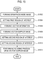
- FIG. 15 is a flow chart showing a process of providing the user interface.
- the processing unit 130 is configured to form the brightness mode image BI based on the brightness mode ultrasound data provided from the ultrasound data acquiring unit 120, at step S1502 in FIG. 15 .
- the brightness mode image BI is displayed on a display unit 150.
- the processing unit 130 is configured to set the first region of interest ROI 1 on the brightness mode image BI based on the input information (i.e., first input information) provided from the user input unit 110, at step S1504 in FIG. 15 .
- the ultrasound data acquiring unit 120 is configured to transmit the ultrasound signals to the living body and receive the ultrasound echo signals from the living body to acquire the Doppler mode ultrasound data corresponding to the first region of interest ROI 1 .
- the processing unit 130 is configured to form vector information based on the Doppler mode ultrasound data provided from the ultrasound data acquiring unit 120, at step S1506 in FIG. 15 . That is, the processing unit 130 forms the vector information corresponding to the motion (i.e., velocity and direction) of the target object based on the Doppler mode ultrasound data.
- X represents a reflector velocity (i.e., velocity of target object)
- Co represents a sound speed in the living body
- f d represents a Doppler shift frequency
- f 0 represents an ultrasound frequency
- the Doppler shift frequency f d is calculated by the difference between a frequency of the ultrasound signals (i.e., transmission beam) and a frequency of the ultrasound echo signals (i.e., reception beam). Also, the velocity component Xcos ⁇ projected to the transmission direction is calculated by equation 1.
- ⁇ T represents an angle between the ultrasound signals (i.e., transmission beam) and the blood flow
- ⁇ R represents an angle between the ultrasound echo signals (i.e., reception beam) and the blood flow.
- FIG. 16 is a schematic diagram showing an example of the transmission directions, the reception directions, the vector information and an over-determined problem.
- the ultrasound signals i.e., transmission beam
- the ultrasound echo signals i.e., reception beam
- ⁇ 1 ( ⁇ 11 , ⁇ 12 ) represents a unit vector of the first direction D1
- X ( x 1 , x 2 ) represents variables
- y 1 is calculated by equation 1.
- the ultrasound signals i.e., transmission beam
- the ultrasound echo signals i.e., reception beam
- the reception beam-forming is performed in at least two angles (i.e., at least two reception directions), at least two equations are obtained and represented as the over-determined problem, as shown in FIG. 16 .
- the over-determined problem is well known in the art. Thus, it has not been described in detail so as not to unnecessarily obscure the present disclosure.
- the over-determined problem is solved by a pseudo inverse method, a weighted least square method and the like based on noise characteristics added to the Doppler shift frequency. That is, M ⁇ N equations are obtained by M transmission directions and the reception beam-forming of N reception directions at every transmission.
- the processing unit 130 is configured to form a vector Doppler image VDI as shown in FIG. 17 based on the vector information, at step S1508 in FIG. 15 .
- the methods of forming the vector Doppler image VDI are well known in the art. Thus, they have not been described in detail so as not to unnecessarily obscure the present disclosure.
- the processing unit 130 is configured to compound the brightness mode image BI and the vector Doppler image VDI to form a compound image.
- the processing unit 130 is configured to form the user interface GUI as shown in FIG. 17 based on the vector information, at step S1510 in FIG. 15 .
- the user interface GUI is an interface mapping the vector information corresponding to the motion (i.e., velocity and direction) of the target object to colors. That is, the user interface GUI is an interface for performing a filtering process upon the vector Doppler image VDI.
- the user interface GUI is displayed on the display unit 150.
- the processing unit 130 is configured to set a second region of interest on the user interface GUI based on the input information (i.e., second input information), at step S1512 in FIG. 15 .
- the processing unit 130 is configured to set the second region of interest ROI 2 including the region RG corresponding to the second input information with respect to a center of the user interface GUI.
- the second input information for setting two regions RG 1 , RG 2 on the user interface GUI in the touch type as shown in FIG. 20 is provided from the user input unit 110, and the processing unit 130 is configured to set the second region of interest ROI 2 including the two regions RG 1 , RG 2 corresponding to the second input information based on the center of the user interface GUI.
- the processing unit 130 is configured to perform a filtering process upon the vector Doppler image VDI based on the second region of interest ROI 2 , at step S1514 in FIG. 15 .
- the processing unit 130 is configured to perform the filtering process for representing only the vector information (i.e., velocity and direction of the target object) corresponding to the second region of interest ROI 2 upon the vector Doppler image VDI. That is, the processing unit 130 performs the filtering process for not representing the vector information not corresponding to the second region of interest ROI 2 upon the vector Doppler image VDI.
- the filtering process for representing only the vector information corresponding to the second region of interest ROI 2 is performed upon the vector Doppler image VDI.
- the ultrasound system 100 further includes the storage unit 140.
- the storage unit 140 stores the ultrasound data (i.e., brightness mode ultrasound data and Doppler mode ultrasound data) acquired by the ultrasound data acquiring unit 120.
- the storage unit 140 additionally stores the vector information formed by the processing unit 130.
- the ultrasound system 100 further includes the display unit 150.
- the display unit 150 is configured to display the brightness mode image BI formed by the processing unit 130.
- the display unit 150 is also configured to display the vector Doppler image VDI formed by the processing unit 130.
- the display unit 150 is additionally configured to display the user interface GUI formed by the processing unit 130.
Landscapes
- Health & Medical Sciences (AREA)
- Life Sciences & Earth Sciences (AREA)
- Engineering & Computer Science (AREA)
- Physics & Mathematics (AREA)
- Heart & Thoracic Surgery (AREA)
- Medical Informatics (AREA)
- Veterinary Medicine (AREA)
- Public Health (AREA)
- General Health & Medical Sciences (AREA)
- Biophysics (AREA)
- Nuclear Medicine, Radiotherapy & Molecular Imaging (AREA)
- Pathology (AREA)
- Radiology & Medical Imaging (AREA)
- Biomedical Technology (AREA)
- Animal Behavior & Ethology (AREA)
- Surgery (AREA)
- Molecular Biology (AREA)
- Radar, Positioning & Navigation (AREA)
- Remote Sensing (AREA)
- General Physics & Mathematics (AREA)
- Computer Networks & Wireless Communication (AREA)
- Acoustics & Sound (AREA)
- Multimedia (AREA)
- Hematology (AREA)
- Human Computer Interaction (AREA)
- Theoretical Computer Science (AREA)
- Computer Vision & Pattern Recognition (AREA)
- Ultra Sonic Daignosis Equipment (AREA)
Claims (6)
- Ein Ultraschallsystem (100), umfassend:eine Ultraschalldaten-Erfassungseinheit (120), die so konfiguriert ist, dass sie Ultraschallsignale an einen lebenden Körper sendet, wobei der lebende Körper ein Zielobjekt enthält, und dass sie Ultraschalldaten von dem lebenden Körper empfängt;eine Benutzereingabe (110);eine Anzeigeeinheit (150);eine Verarbeitungseinheit (130), die dazu konfiguriert ist:ein Helligkeitsmodusbild auf der Grundlage der Ultraschalldaten zu bilden,eine erste Region von Interesse (ROI1) auf dem Bild des Helligkeitsmodus auf der Grundlage der ersten Eingabeinformationen, die von der Benutzereingabeeinheit (110) bereitgestellt werden, einzustellen;
Vektorinformationen eines Zielobjekts zu bilden, das dem ersten Bereich von Interesse (ROI1) entspricht, auf der Grundlage von Doppler-Modus-Ultraschalldaten, die der Bewegung des Zielobjekts entsprechen, wobei die Vektorinformationen eine Richtung und eine Geschwindigkeit des Zielobjekts umfassen;ein Vektor-Doppler-Bild basierend auf der Vektorinformation zu bilden, das Bild des Helligkeitsmodus und das Vektor-Doppler-Bild zu einem zusammengesetzten Bild zusammenzusetzen;eine Benutzerschnittstelle zu bilden, die die Vektorinformation einschließlich der Geschwindigkeit und der Richtung der Bewegung des Zielobjekts in Farben abbildet, wobei die Benutzerschnittstelle kreisförmig und berührend ist,einen zweiten Bereich von Interesse (ROI2) auf der Benutzerschnittstelle auf der Grundlage von zweiten Eingabeinformationen festzulegen, wobei der zweite Bereich von Interesse (ROI2) einen Bereich enthält, der den zweiten Eingabeinformationen in Bezug auf die Mitte der Benutzerschnittstelle entspricht; undwobei als Reaktion auf die Auswahl des zweiten interessierenden Bereichs (ROI2) die Verarbeitungseinheit (130) ferner so konfiguriert ist, dass sie einen Filterprozess an dem Vektor-Doppler-Bild durchführt, indem sie das Vektor-Doppler-Bild anzeigt, das nur Geschwindigkeiten und Richtungen entsprechend dem zweiten interessierenden Bereich aus den Vektorinformationen des Zielobjekts darstellt,wobei die Anzeigeeinheit (150) konfiguriert ist, um das Bild im Helligkeitsmodus, den Vektor-Doppler und die Benutzerschnittstelle anzuzeigen; unddie Benutzereingabeeinheit (110) so konfiguriert ist, dass sie Eingabeinformationen von einem Benutzer empfängt, wobei die Eingabeinformationen erste Eingabeinformationen zum Einstellen eines ersten Bereichs von Interesse (ROI1) auf einem Bild im Helligkeitsmodus und zweite Eingabeinformationen zum Auswählen des zweiten Bereichs von Interesse (ROI2) auf der Benutzerschnittstelle umfassen. - Ultraschallsystem (100) nach Anspruch 1, wobei die Verarbeitungseinheit (130) so konfiguriert ist, dass sie die der Geschwindigkeit und der Richtung des Zielobjektes entsprechende Vektorinformation unter Berücksichtigung mindestens einer Senderichtung und mindestens einer der mindestens einen Senderichtung entsprechenden Empfangsrichtung auf Basis der Ultraschalldaten bildet.
- Ultraschallsystem (100) nach Anspruch 1, wobei die Ultraschalldatenerfassungseinheit (120) konfiguriert ist, um Ultraschallsignale zu dem lebenden Körper einschließlich des Zielobjekts in mindestens einer Senderichtung zu senden, wobei die Ultraschalldatenerfassungseinheit (120) ferner konfiguriert ist, um Ultraschallechosignale von dem lebenden Körper in mindestens einer Empfangsrichtung zu empfangen, um die der mindestens einen Empfangsrichtung entsprechenden Ultraschalldaten zu erfassen.
- Ultraschall-Abbildungsverfahren für das System nach Anspruch 1, umfassend die Schritte:Übertragen von Ultraschallsignalen an einen lebenden Körper, wobei der lebende Körper ein Zielobjekt enthält, und Empfangen von Ultraschalldaten von dem lebenden Körper;Erzeugen eines Helligkeitsmodusbildes auf der Grundlage der Ultraschalldaten;Einstellen eines ersten Bereichs von Interesse (ROI1) auf dem Bild im Helligkeitsmodus auf der Grundlage von ersten Eingabeinformationen, die von der Benutzereingabeeinheit (110) bereitgestellt werden;Bilden von Vektorinformationen eines Zielobjekts, die dem ersten Bereich von Interesse (ROI1) entsprechen, auf der Grundlage von Doppler-Modus-Ultraschalldaten, die der Bewegung des Zielobjekts entsprechen, wobei die Vektorinformationen eine Richtung und eine Geschwindigkeit des Zielobjekts enthalten;Bilden eines Vektor-Doppler-Bildes basierend auf der Vektorinformation, Zusammensetzen des Helligkeitsmodus-Bildes und des Vektor-Doppler-Bildes zu einem zusammengesetzten Bild;Bilden einer Benutzerschnittstelle, Abbilden der Vektorinformation einschließlich der Geschwindigkeit und der Richtung der Bewegung des Zielobjekts in Farben, wobei die Benutzerschnittstelle kreisförmig und berührend ist,Festlegen eines zweiten Bereichs von Interesse (ROI2) auf der Benutzerschnittstelle auf der Grundlage von zweiten Eingabeinformationen, wobei der zweite Bereich von Interesse (ROI2) einen Bereich enthält, der den zweiten Eingabeinformationen in Bezug auf die Mitte der Benutzerschnittstelle entspricht; undals Reaktion auf die Auswahl des zweiten interessierenden Bereichs (ROI2), Durchführen eines Filterprozesses auf dem Vektor-Doppler-Bild durch Anzeigen des Vektor-Doppler-Bildes, das nur Geschwindigkeiten und Richtungen entsprechend dem zweiten Bereich von Interesse aus den Vektorinformationen des Zielobjekts darstellt, und ferner Anzeigen des Bildes im Helligkeitsmodus, des Vektor-Dopplers und der Benutzerschnittstelle; unddie Eingabeinformationen umfassen erste Eingabeinformationen zur Einstellung eines ersten Bereichs von Interesse (ROI1) auf einem Bild im Helligkeitsmodus und eine zweite Eingabeinformation zur Auswahl des zweiten Bereichs von Interesse (ROI2) auf der Benutzeroberfläche.
- Verfahren nach Anspruch 4, wobei der Schritt des Bildens von Vektorinformation umfasst:
Bilden der der Geschwindigkeit und der Richtung des Zielobjektes entsprechenden Vektorinformation unter Berücksichtigung mindestens einer Senderichtung und mindestens einer der mindestens einen Senderichtung entsprechenden Empfangsrichtung auf der Basis der Ultraschalldaten. - Verfahren nach Anspruch 4, weiter umfassend:
Senden von Ultraschallsignalen zu einem lebenden Körper, der das Zielobjekt enthält, in mindestens einer Senderichtung und Empfangen von Ultraschall-Echosignalen von dem lebenden Körper in mindestens einer Empfangsrichtung, um die Ultraschalldaten entsprechend der mindestens einen Empfangsrichtung zu erfassen, bevor der Schritt der Bildung eines Helligkeitsmodusbildes durchgeführt wird.
Applications Claiming Priority (1)
| Application Number | Priority Date | Filing Date | Title |
|---|---|---|---|
| KR1020110144476A KR101406807B1 (ko) | 2011-12-28 | 2011-12-28 | 사용자 인터페이스를 제공하는 초음파 시스템 및 방법 |
Publications (2)
| Publication Number | Publication Date |
|---|---|
| EP2609868A1 EP2609868A1 (de) | 2013-07-03 |
| EP2609868B1 true EP2609868B1 (de) | 2020-03-18 |
Family
ID=47713776
Family Applications (1)
| Application Number | Title | Priority Date | Filing Date |
|---|---|---|---|
| EP12199541.9A Active EP2609868B1 (de) | 2011-12-28 | 2012-12-27 | Bereitstellung einer Benutzerschnittstelle in einem Ultraschallsystem |
Country Status (3)
| Country | Link |
|---|---|
| US (2) | US20130172748A1 (de) |
| EP (1) | EP2609868B1 (de) |
| KR (1) | KR101406807B1 (de) |
Families Citing this family (12)
| Publication number | Priority date | Publication date | Assignee | Title |
|---|---|---|---|---|
| US10667790B2 (en) | 2012-03-26 | 2020-06-02 | Teratech Corporation | Tablet ultrasound system |
| US9877699B2 (en) | 2012-03-26 | 2018-01-30 | Teratech Corporation | Tablet ultrasound system |
| WO2016012572A1 (en) * | 2014-07-24 | 2016-01-28 | Hze Aps | Flow estimation |
| EP3220828B1 (de) | 2014-11-18 | 2021-12-22 | C.R. Bard, Inc. | Ultraschallbildgebungssystem mit automatischer bilddarstellung |
| US10646201B2 (en) | 2014-11-18 | 2020-05-12 | C. R. Bard, Inc. | Ultrasound imaging system having automatic image presentation |
| CN108882916B (zh) * | 2016-09-30 | 2022-06-10 | 深圳迈瑞生物医疗电子股份有限公司 | 超声血流的参数显示方法及其超声成像系统 |
| US10945706B2 (en) | 2017-05-05 | 2021-03-16 | Biim Ultrasound As | Hand held ultrasound probe |
| US12102475B2 (en) * | 2020-06-26 | 2024-10-01 | Siemens Medical Solutions Usa, Inc. | Image classification-dependent user interface in ultrasound imaging |
| WO2022219631A1 (en) * | 2021-04-13 | 2022-10-20 | Tel Hashomer Medical Research Infrastructure And Services Ltd. | Systems and methods for reconstruction of 3d images from ultrasound and camera images |
| EP4195014A1 (de) * | 2021-12-13 | 2023-06-14 | Dassault Systèmes | Benutzerschnittstelle für mehrfach-rendering |
| US20230225711A1 (en) * | 2022-01-17 | 2023-07-20 | Clarius Mobile Health Corp. | Systems and methods for automatically determining and displaying a vascular depth measurement on an ultrasound image displayed on a device |
| JP7828222B2 (ja) * | 2022-04-07 | 2026-03-11 | 富士フイルム株式会社 | 超音波診断装置及びビーム形成方法 |
Family Cites Families (32)
| Publication number | Priority date | Publication date | Assignee | Title |
|---|---|---|---|---|
| JPS62152439A (ja) * | 1985-12-26 | 1987-07-07 | アロカ株式会社 | 超音波画像形成装置 |
| US5123417A (en) * | 1990-07-19 | 1992-06-23 | Diasonics, Inc. | Apparatus and method for displaying ultrasonic data |
| US5622174A (en) * | 1992-10-02 | 1997-04-22 | Kabushiki Kaisha Toshiba | Ultrasonic diagnosis apparatus and image displaying system |
| JP3610129B2 (ja) | 1995-09-18 | 2005-01-12 | ジーイー横河メディカルシステム株式会社 | 画像表示方法および装置並びに超音波診断装置 |
| JP3784109B2 (ja) | 1996-07-08 | 2006-06-07 | 株式会社日立メディコ | 超音波映像装置 |
| JP4074705B2 (ja) | 1998-04-20 | 2008-04-09 | フクダ電子株式会社 | 超音波診断装置 |
| US5910119A (en) * | 1998-05-12 | 1999-06-08 | Diasonics, Inc. | Ultrasonic color doppler velocity and direction imaging |
| JP2000139914A (ja) | 1998-11-04 | 2000-05-23 | Aloka Co Ltd | 超音波診断装置 |
| US6176828B1 (en) * | 1998-12-24 | 2001-01-23 | General Electric Company | Method and apparatus for optimal data mapping of power doppler images |
| US20020173721A1 (en) * | 1999-08-20 | 2002-11-21 | Novasonics, Inc. | User interface for handheld imaging devices |
| US20030013959A1 (en) * | 1999-08-20 | 2003-01-16 | Sorin Grunwald | User interface for handheld imaging devices |
| JP2002017685A (ja) | 2000-07-10 | 2002-01-22 | Ge Yokogawa Medical Systems Ltd | 医用画像表示方法および医用画像表示装置 |
| US6755789B2 (en) * | 2002-02-05 | 2004-06-29 | Inceptio Medical Technologies, Llc | Ultrasonic vascular imaging system and method of blood vessel cannulation |
| WO2004109330A1 (en) * | 2003-06-10 | 2004-12-16 | Koninklijke Philips Electronics, N.V. | User interface for a three-dimensional colour ultrasound imaging system |
| JP4713862B2 (ja) * | 2004-08-23 | 2011-06-29 | 株式会社東芝 | 超音波診断装置 |
| KR100825054B1 (ko) | 2005-06-28 | 2008-04-28 | 주식회사 메디슨 | 컬러 플로우 영상을 촬상하는 방법 및 초음파 진단 시스템 |
| US20070083099A1 (en) * | 2005-09-29 | 2007-04-12 | Henderson Stephen W | Path related three dimensional medical imaging |
| KR100951595B1 (ko) | 2006-10-17 | 2010-04-09 | 주식회사 메디슨 | 초음파 영상을 형성하는 초음파 시스템 및 방법 |
| AU2008200011B2 (en) * | 2007-01-05 | 2012-08-23 | Olympus Medical Systems Corp. | Ultrasonic diagnostic equipment and method for processing signal of ultrasonic diagnostic equipment |
| CN101636113B (zh) * | 2007-04-27 | 2011-09-21 | 株式会社日立医药 | 超声波诊断装置 |
| JP5063216B2 (ja) | 2007-06-27 | 2012-10-31 | 日立アロカメディカル株式会社 | 超音波診断装置及び処理プログラム |
| JP5214920B2 (ja) * | 2007-07-24 | 2013-06-19 | 株式会社東芝 | 超音波診断装置及び超音波診断装置の音響出力方法 |
| CN102006828B (zh) | 2008-03-03 | 2014-08-27 | 柯尼卡美能达株式会社 | 超声波诊断装置 |
| JP2009285244A (ja) | 2008-05-30 | 2009-12-10 | Panasonic Corp | 超音波診断装置 |
| KR101027566B1 (ko) | 2008-11-17 | 2011-04-06 | (주)메디슨 | 초음파 진단기 및 초음파 진단기에서의 명령 신호 생성 방법 |
| KR101313218B1 (ko) * | 2008-12-08 | 2013-09-30 | 삼성메디슨 주식회사 | 휴대형 초음파 시스템 |
| KR101167248B1 (ko) | 2009-05-22 | 2012-07-23 | 삼성메디슨 주식회사 | 터치 인터랙션을 사용하는 초음파 진단 장치 |
| EP2264483B1 (de) | 2009-06-01 | 2017-11-29 | Samsung Medison Co., Ltd. | Ultraschallsystem und Verfahren zur Bereitstellung eines Bewegungsvektors |
| KR101120812B1 (ko) * | 2009-06-01 | 2012-03-22 | 삼성메디슨 주식회사 | 움직임 벡터를 제공하는 초음파 시스템 및 방법 |
| US9204858B2 (en) * | 2010-02-05 | 2015-12-08 | Ultrasonix Medical Corporation | Ultrasound pulse-wave doppler measurement of blood flow velocity and/or turbulence |
| US20110246217A1 (en) * | 2010-04-05 | 2011-10-06 | MobiSante Inc. | Sampling Patient Data |
| WO2014058929A1 (en) * | 2012-10-08 | 2014-04-17 | Fujifilm Sonosite, Inc. | Systems and methods for touch-based input on ultrasound devices |
-
2011
- 2011-12-28 KR KR1020110144476A patent/KR101406807B1/ko active Active
-
2012
- 2012-12-27 EP EP12199541.9A patent/EP2609868B1/de active Active
- 2012-12-28 US US13/730,501 patent/US20130172748A1/en not_active Abandoned
-
2017
- 2017-03-23 US US15/467,882 patent/US11406362B2/en active Active
Non-Patent Citations (1)
| Title |
|---|
| VERA N ET AL: "Visualization of complex flow fields, with application to the interpretation of colour flow doppler images", ULTRASOUND IN MEDICINE AND BIOLOGY, NEW YORK, NY, US, vol. 18, no. 1, 1 January 1992 (1992-01-01), pages 1 - 9, XP026450892, ISSN: 0301-5629, [retrieved on 19920101] * |
Also Published As
| Publication number | Publication date |
|---|---|
| KR101406807B1 (ko) | 2014-06-12 |
| US20170188998A1 (en) | 2017-07-06 |
| US20130172748A1 (en) | 2013-07-04 |
| KR20130076064A (ko) | 2013-07-08 |
| US11406362B2 (en) | 2022-08-09 |
| EP2609868A1 (de) | 2013-07-03 |
Similar Documents
| Publication | Publication Date | Title |
|---|---|---|
| EP2609868B1 (de) | Bereitstellung einer Benutzerschnittstelle in einem Ultraschallsystem | |
| EP2609871A1 (de) | Bereitstellung eines Vektordopplerbildes auf Grundlage von Entscheidungsdaten in einem Ultraschallsystem | |
| US20130165784A1 (en) | Providing motion profile information of target object in ultrasound system | |
| EP2609870A1 (de) | Bereitstellung von Wirbelströmungsinformationen auf Grundlage eines Vektordopplers in einem Ultraschallsystem | |
| EP2610635A2 (de) | Erstellung von spektralen Doppler Bildern, die mindestens zwei Probenvolumen entsprechen | |
| EP2610639A2 (de) | Einschätzung der Bewegung eines Teilchens basierend auf dem Vektordoppler in einem Ultraschallsystem | |
| EP2609866B1 (de) | Bereitstellung von Bewegungsmodusbildern in einem Ultraschallsystem | |
| US8306296B2 (en) | Clutter signal filtering using eigenvectors in an ultrasound system | |
| US9474510B2 (en) | Ultrasound and system for forming an ultrasound image | |
| EP2610638B1 (de) | Erzeugung von Vektorinformationen basierend auf dem Vektordoppler in einem Ultraschallsystem | |
| US9510803B2 (en) | Providing compound image of doppler spectrum images in ultrasound system | |
| US20130165793A1 (en) | Providing doppler information of target object based on vector doppler in ultrasound system | |
| EP2609869A1 (de) | Bereitstellung von Partikelflussbildern in einem Ultraschallsystem | |
| EP2610640B1 (de) | Ultraschallsystem und Verfahren zur Vektorinformationserkennung mittels Übertragungsverzögerungen |
Legal Events
| Date | Code | Title | Description |
|---|---|---|---|
| PUAI | Public reference made under article 153(3) epc to a published international application that has entered the european phase |
Free format text: ORIGINAL CODE: 0009012 |
|
| AK | Designated contracting states |
Kind code of ref document: A1 Designated state(s): AL AT BE BG CH CY CZ DE DK EE ES FI FR GB GR HR HU IE IS IT LI LT LU LV MC MK MT NL NO PL PT RO RS SE SI SK SM TR |
|
| AX | Request for extension of the european patent |
Extension state: BA ME |
|
| 17P | Request for examination filed |
Effective date: 20140103 |
|
| RBV | Designated contracting states (corrected) |
Designated state(s): AL AT BE BG CH CY CZ DE DK EE ES FI FR GB GR HR HU IE IS IT LI LT LU LV MC MK MT NL NO PL PT RO RS SE SI SK SM TR |
|
| STAA | Information on the status of an ep patent application or granted ep patent |
Free format text: STATUS: EXAMINATION IS IN PROGRESS |
|
| 17Q | First examination report despatched |
Effective date: 20171020 |
|
| GRAP | Despatch of communication of intention to grant a patent |
Free format text: ORIGINAL CODE: EPIDOSNIGR1 |
|
| STAA | Information on the status of an ep patent application or granted ep patent |
Free format text: STATUS: GRANT OF PATENT IS INTENDED |
|
| INTG | Intention to grant announced |
Effective date: 20191022 |
|
| GRAS | Grant fee paid |
Free format text: ORIGINAL CODE: EPIDOSNIGR3 |
|
| GRAA | (expected) grant |
Free format text: ORIGINAL CODE: 0009210 |
|
| STAA | Information on the status of an ep patent application or granted ep patent |
Free format text: STATUS: THE PATENT HAS BEEN GRANTED |
|
| AK | Designated contracting states |
Kind code of ref document: B1 Designated state(s): AL AT BE BG CH CY CZ DE DK EE ES FI FR GB GR HR HU IE IS IT LI LT LU LV MC MK MT NL NO PL PT RO RS SE SI SK SM TR |
|
| REG | Reference to a national code |
Ref country code: GB Ref legal event code: FG4D |
|
| REG | Reference to a national code |
Ref country code: DE Ref legal event code: R096 Ref document number: 602012068546 Country of ref document: DE |
|
| REG | Reference to a national code |
Ref country code: AT Ref legal event code: REF Ref document number: 1244967 Country of ref document: AT Kind code of ref document: T Effective date: 20200415 Ref country code: IE Ref legal event code: FG4D |
|
| PG25 | Lapsed in a contracting state [announced via postgrant information from national office to epo] |
Ref country code: FI Free format text: LAPSE BECAUSE OF FAILURE TO SUBMIT A TRANSLATION OF THE DESCRIPTION OR TO PAY THE FEE WITHIN THE PRESCRIBED TIME-LIMIT Effective date: 20200318 Ref country code: RS Free format text: LAPSE BECAUSE OF FAILURE TO SUBMIT A TRANSLATION OF THE DESCRIPTION OR TO PAY THE FEE WITHIN THE PRESCRIBED TIME-LIMIT Effective date: 20200318 Ref country code: NO Free format text: LAPSE BECAUSE OF FAILURE TO SUBMIT A TRANSLATION OF THE DESCRIPTION OR TO PAY THE FEE WITHIN THE PRESCRIBED TIME-LIMIT Effective date: 20200618 |
|
| REG | Reference to a national code |
Ref country code: NL Ref legal event code: MP Effective date: 20200318 |
|
| PG25 | Lapsed in a contracting state [announced via postgrant information from national office to epo] |
Ref country code: SE Free format text: LAPSE BECAUSE OF FAILURE TO SUBMIT A TRANSLATION OF THE DESCRIPTION OR TO PAY THE FEE WITHIN THE PRESCRIBED TIME-LIMIT Effective date: 20200318 Ref country code: LV Free format text: LAPSE BECAUSE OF FAILURE TO SUBMIT A TRANSLATION OF THE DESCRIPTION OR TO PAY THE FEE WITHIN THE PRESCRIBED TIME-LIMIT Effective date: 20200318 Ref country code: GR Free format text: LAPSE BECAUSE OF FAILURE TO SUBMIT A TRANSLATION OF THE DESCRIPTION OR TO PAY THE FEE WITHIN THE PRESCRIBED TIME-LIMIT Effective date: 20200619 Ref country code: HR Free format text: LAPSE BECAUSE OF FAILURE TO SUBMIT A TRANSLATION OF THE DESCRIPTION OR TO PAY THE FEE WITHIN THE PRESCRIBED TIME-LIMIT Effective date: 20200318 Ref country code: BG Free format text: LAPSE BECAUSE OF FAILURE TO SUBMIT A TRANSLATION OF THE DESCRIPTION OR TO PAY THE FEE WITHIN THE PRESCRIBED TIME-LIMIT Effective date: 20200618 |
|
| REG | Reference to a national code |
Ref country code: LT Ref legal event code: MG4D |
|
| PG25 | Lapsed in a contracting state [announced via postgrant information from national office to epo] |
Ref country code: NL Free format text: LAPSE BECAUSE OF FAILURE TO SUBMIT A TRANSLATION OF THE DESCRIPTION OR TO PAY THE FEE WITHIN THE PRESCRIBED TIME-LIMIT Effective date: 20200318 |
|
| PG25 | Lapsed in a contracting state [announced via postgrant information from national office to epo] |
Ref country code: IS Free format text: LAPSE BECAUSE OF FAILURE TO SUBMIT A TRANSLATION OF THE DESCRIPTION OR TO PAY THE FEE WITHIN THE PRESCRIBED TIME-LIMIT Effective date: 20200718 Ref country code: EE Free format text: LAPSE BECAUSE OF FAILURE TO SUBMIT A TRANSLATION OF THE DESCRIPTION OR TO PAY THE FEE WITHIN THE PRESCRIBED TIME-LIMIT Effective date: 20200318 Ref country code: SM Free format text: LAPSE BECAUSE OF FAILURE TO SUBMIT A TRANSLATION OF THE DESCRIPTION OR TO PAY THE FEE WITHIN THE PRESCRIBED TIME-LIMIT Effective date: 20200318 Ref country code: RO Free format text: LAPSE BECAUSE OF FAILURE TO SUBMIT A TRANSLATION OF THE DESCRIPTION OR TO PAY THE FEE WITHIN THE PRESCRIBED TIME-LIMIT Effective date: 20200318 Ref country code: SK Free format text: LAPSE BECAUSE OF FAILURE TO SUBMIT A TRANSLATION OF THE DESCRIPTION OR TO PAY THE FEE WITHIN THE PRESCRIBED TIME-LIMIT Effective date: 20200318 Ref country code: CZ Free format text: LAPSE BECAUSE OF FAILURE TO SUBMIT A TRANSLATION OF THE DESCRIPTION OR TO PAY THE FEE WITHIN THE PRESCRIBED TIME-LIMIT Effective date: 20200318 Ref country code: LT Free format text: LAPSE BECAUSE OF FAILURE TO SUBMIT A TRANSLATION OF THE DESCRIPTION OR TO PAY THE FEE WITHIN THE PRESCRIBED TIME-LIMIT Effective date: 20200318 Ref country code: PT Free format text: LAPSE BECAUSE OF FAILURE TO SUBMIT A TRANSLATION OF THE DESCRIPTION OR TO PAY THE FEE WITHIN THE PRESCRIBED TIME-LIMIT Effective date: 20200812 |
|
| REG | Reference to a national code |
Ref country code: AT Ref legal event code: MK05 Ref document number: 1244967 Country of ref document: AT Kind code of ref document: T Effective date: 20200318 |
|
| REG | Reference to a national code |
Ref country code: DE Ref legal event code: R097 Ref document number: 602012068546 Country of ref document: DE |
|
| PLBE | No opposition filed within time limit |
Free format text: ORIGINAL CODE: 0009261 |
|
| STAA | Information on the status of an ep patent application or granted ep patent |
Free format text: STATUS: NO OPPOSITION FILED WITHIN TIME LIMIT |
|
| PG25 | Lapsed in a contracting state [announced via postgrant information from national office to epo] |
Ref country code: DK Free format text: LAPSE BECAUSE OF FAILURE TO SUBMIT A TRANSLATION OF THE DESCRIPTION OR TO PAY THE FEE WITHIN THE PRESCRIBED TIME-LIMIT Effective date: 20200318 Ref country code: AT Free format text: LAPSE BECAUSE OF FAILURE TO SUBMIT A TRANSLATION OF THE DESCRIPTION OR TO PAY THE FEE WITHIN THE PRESCRIBED TIME-LIMIT Effective date: 20200318 Ref country code: ES Free format text: LAPSE BECAUSE OF FAILURE TO SUBMIT A TRANSLATION OF THE DESCRIPTION OR TO PAY THE FEE WITHIN THE PRESCRIBED TIME-LIMIT Effective date: 20200318 |
|
| 26N | No opposition filed |
Effective date: 20201221 |
|
| PG25 | Lapsed in a contracting state [announced via postgrant information from national office to epo] |
Ref country code: PL Free format text: LAPSE BECAUSE OF FAILURE TO SUBMIT A TRANSLATION OF THE DESCRIPTION OR TO PAY THE FEE WITHIN THE PRESCRIBED TIME-LIMIT Effective date: 20200318 |
|
| PG25 | Lapsed in a contracting state [announced via postgrant information from national office to epo] |
Ref country code: SI Free format text: LAPSE BECAUSE OF FAILURE TO SUBMIT A TRANSLATION OF THE DESCRIPTION OR TO PAY THE FEE WITHIN THE PRESCRIBED TIME-LIMIT Effective date: 20200318 |
|
| REG | Reference to a national code |
Ref country code: CH Ref legal event code: PL |
|
| GBPC | Gb: european patent ceased through non-payment of renewal fee |
Effective date: 20201227 |
|
| PG25 | Lapsed in a contracting state [announced via postgrant information from national office to epo] |
Ref country code: MC Free format text: LAPSE BECAUSE OF FAILURE TO SUBMIT A TRANSLATION OF THE DESCRIPTION OR TO PAY THE FEE WITHIN THE PRESCRIBED TIME-LIMIT Effective date: 20200318 |
|
| REG | Reference to a national code |
Ref country code: BE Ref legal event code: MM Effective date: 20201231 |
|
| PG25 | Lapsed in a contracting state [announced via postgrant information from national office to epo] |
Ref country code: IE Free format text: LAPSE BECAUSE OF NON-PAYMENT OF DUE FEES Effective date: 20201227 Ref country code: LU Free format text: LAPSE BECAUSE OF NON-PAYMENT OF DUE FEES Effective date: 20201227 |
|
| PG25 | Lapsed in a contracting state [announced via postgrant information from national office to epo] |
Ref country code: LI Free format text: LAPSE BECAUSE OF NON-PAYMENT OF DUE FEES Effective date: 20201231 Ref country code: GB Free format text: LAPSE BECAUSE OF NON-PAYMENT OF DUE FEES Effective date: 20201227 Ref country code: CH Free format text: LAPSE BECAUSE OF NON-PAYMENT OF DUE FEES Effective date: 20201231 |
|
| PG25 | Lapsed in a contracting state [announced via postgrant information from national office to epo] |
Ref country code: TR Free format text: LAPSE BECAUSE OF FAILURE TO SUBMIT A TRANSLATION OF THE DESCRIPTION OR TO PAY THE FEE WITHIN THE PRESCRIBED TIME-LIMIT Effective date: 20200318 Ref country code: MT Free format text: LAPSE BECAUSE OF FAILURE TO SUBMIT A TRANSLATION OF THE DESCRIPTION OR TO PAY THE FEE WITHIN THE PRESCRIBED TIME-LIMIT Effective date: 20200318 Ref country code: CY Free format text: LAPSE BECAUSE OF FAILURE TO SUBMIT A TRANSLATION OF THE DESCRIPTION OR TO PAY THE FEE WITHIN THE PRESCRIBED TIME-LIMIT Effective date: 20200318 |
|
| PG25 | Lapsed in a contracting state [announced via postgrant information from national office to epo] |
Ref country code: MK Free format text: LAPSE BECAUSE OF FAILURE TO SUBMIT A TRANSLATION OF THE DESCRIPTION OR TO PAY THE FEE WITHIN THE PRESCRIBED TIME-LIMIT Effective date: 20200318 Ref country code: AL Free format text: LAPSE BECAUSE OF FAILURE TO SUBMIT A TRANSLATION OF THE DESCRIPTION OR TO PAY THE FEE WITHIN THE PRESCRIBED TIME-LIMIT Effective date: 20200318 |
|
| PG25 | Lapsed in a contracting state [announced via postgrant information from national office to epo] |
Ref country code: BE Free format text: LAPSE BECAUSE OF NON-PAYMENT OF DUE FEES Effective date: 20201231 |
|
| PGFP | Annual fee paid to national office [announced via postgrant information from national office to epo] |
Ref country code: DE Payment date: 20251105 Year of fee payment: 14 |
|
| PGFP | Annual fee paid to national office [announced via postgrant information from national office to epo] |
Ref country code: IT Payment date: 20251106 Year of fee payment: 14 |
|
| PGFP | Annual fee paid to national office [announced via postgrant information from national office to epo] |
Ref country code: FR Payment date: 20251111 Year of fee payment: 14 |