EP3220828B1 - Ultraschallbildgebungssystem mit automatischer bilddarstellung - Google Patents
Ultraschallbildgebungssystem mit automatischer bilddarstellung Download PDFInfo
- Publication number
- EP3220828B1 EP3220828B1 EP15709069.7A EP15709069A EP3220828B1 EP 3220828 B1 EP3220828 B1 EP 3220828B1 EP 15709069 A EP15709069 A EP 15709069A EP 3220828 B1 EP3220828 B1 EP 3220828B1
- Authority
- EP
- European Patent Office
- Prior art keywords
- ultrasound
- dimensional
- probe
- ultrasound transducer
- transducer array
- Prior art date
- Legal status (The legal status is an assumption and is not a legal conclusion. Google has not performed a legal analysis and makes no representation as to the accuracy of the status listed.)
- Active
Links
Images


Classifications
-
- A—HUMAN NECESSITIES
- A61—MEDICAL OR VETERINARY SCIENCE; HYGIENE
- A61B—DIAGNOSIS; SURGERY; IDENTIFICATION
- A61B8/00—Diagnosis using ultrasonic, sonic or infrasonic waves
- A61B8/42—Details of probe positioning or probe attachment to the patient
- A61B8/4245—Details of probe positioning or probe attachment to the patient involving determining the position of the probe, e.g. with respect to an external reference frame or to the patient
- A61B8/4254—Details of probe positioning or probe attachment to the patient involving determining the position of the probe, e.g. with respect to an external reference frame or to the patient using sensors mounted on the probe
-
- A—HUMAN NECESSITIES
- A61—MEDICAL OR VETERINARY SCIENCE; HYGIENE
- A61B—DIAGNOSIS; SURGERY; IDENTIFICATION
- A61B8/00—Diagnosis using ultrasonic, sonic or infrasonic waves
- A61B8/08—Clinical applications
- A61B8/0833—Clinical applications involving detecting or locating foreign bodies or organic structures
- A61B8/0841—Clinical applications involving detecting or locating foreign bodies or organic structures for locating instruments
-
- A—HUMAN NECESSITIES
- A61—MEDICAL OR VETERINARY SCIENCE; HYGIENE
- A61B—DIAGNOSIS; SURGERY; IDENTIFICATION
- A61B8/00—Diagnosis using ultrasonic, sonic or infrasonic waves
- A61B8/42—Details of probe positioning or probe attachment to the patient
- A61B8/4245—Details of probe positioning or probe attachment to the patient involving determining the position of the probe, e.g. with respect to an external reference frame or to the patient
- A61B8/4263—Details of probe positioning or probe attachment to the patient involving determining the position of the probe, e.g. with respect to an external reference frame or to the patient using sensors not mounted on the probe, e.g. mounted on an external reference frame
-
- A—HUMAN NECESSITIES
- A61—MEDICAL OR VETERINARY SCIENCE; HYGIENE
- A61B—DIAGNOSIS; SURGERY; IDENTIFICATION
- A61B8/00—Diagnosis using ultrasonic, sonic or infrasonic waves
- A61B8/44—Constructional features of the ultrasonic, sonic or infrasonic diagnostic device
- A61B8/4405—Device being mounted on a trolley
-
- A—HUMAN NECESSITIES
- A61—MEDICAL OR VETERINARY SCIENCE; HYGIENE
- A61B—DIAGNOSIS; SURGERY; IDENTIFICATION
- A61B8/00—Diagnosis using ultrasonic, sonic or infrasonic waves
- A61B8/44—Constructional features of the ultrasonic, sonic or infrasonic diagnostic device
- A61B8/4444—Constructional features of the ultrasonic, sonic or infrasonic diagnostic device related to the probe
- A61B8/4461—Features of the scanning mechanism, e.g. for moving the transducer within the housing of the probe
-
- A—HUMAN NECESSITIES
- A61—MEDICAL OR VETERINARY SCIENCE; HYGIENE
- A61B—DIAGNOSIS; SURGERY; IDENTIFICATION
- A61B8/00—Diagnosis using ultrasonic, sonic or infrasonic waves
- A61B8/46—Ultrasonic, sonic or infrasonic diagnostic devices with special arrangements for interfacing with the operator or the patient
- A61B8/461—Displaying means of special interest
- A61B8/466—Displaying means of special interest adapted to display 3D data
-
- A—HUMAN NECESSITIES
- A61—MEDICAL OR VETERINARY SCIENCE; HYGIENE
- A61B—DIAGNOSIS; SURGERY; IDENTIFICATION
- A61B8/00—Diagnosis using ultrasonic, sonic or infrasonic waves
- A61B8/48—Diagnostic techniques
- A61B8/483—Diagnostic techniques involving the acquisition of a 3D volume of data
-
- A—HUMAN NECESSITIES
- A61—MEDICAL OR VETERINARY SCIENCE; HYGIENE
- A61B—DIAGNOSIS; SURGERY; IDENTIFICATION
- A61B8/00—Diagnosis using ultrasonic, sonic or infrasonic waves
- A61B8/52—Devices using data or image processing specially adapted for diagnosis using ultrasonic, sonic or infrasonic waves
- A61B8/5215—Devices using data or image processing specially adapted for diagnosis using ultrasonic, sonic or infrasonic waves involving processing of medical diagnostic data
- A61B8/5238—Devices using data or image processing specially adapted for diagnosis using ultrasonic, sonic or infrasonic waves involving processing of medical diagnostic data for combining image data of patient, e.g. merging several images from different acquisition modes into one image
- A61B8/5246—Devices using data or image processing specially adapted for diagnosis using ultrasonic, sonic or infrasonic waves involving processing of medical diagnostic data for combining image data of patient, e.g. merging several images from different acquisition modes into one image combining images from the same or different imaging techniques, e.g. color Doppler and B-mode
-
- A—HUMAN NECESSITIES
- A61—MEDICAL OR VETERINARY SCIENCE; HYGIENE
- A61B—DIAGNOSIS; SURGERY; IDENTIFICATION
- A61B8/00—Diagnosis using ultrasonic, sonic or infrasonic waves
- A61B8/46—Ultrasonic, sonic or infrasonic diagnostic devices with special arrangements for interfacing with the operator or the patient
- A61B8/461—Displaying means of special interest
Definitions
- the present invention relates to ultrasound imaging, and, more particularly, to an ultrasound imaging system that assists in the positioning of an ultrasound probe.
- an ultrasound imaging system as in the present invention, which assists a person not experienced in ultrasound imaging in successful image acquisition, via system assisted positioning of an ultrasound probe, such that an image of a location of interest under, i.e., in the imaging view of, the ultrasound probe can be displayed.
- US 2014/0187919 A1 discloses a system which employs an interventional tool, ultrasound imaging system and a multi-planar reformatting module.
- the interventional tool has one or more image tracking points.
- the ultrasound imaging system includes an ultrasound probe operable for generating an ultrasound volume image of a portion or an entirety of the interventional tool within an anatomical region.
- the multi-planar reformatting imaging module generates two or more multi-planar reformatting images of the interventional tool within the anatomical region.
- a generation of the two multi-planar reformatting images includes an identification of each image tracking point within the ultrasound volume image, and a utilization of each identified image tracking point as an origin of the multi-planar reformatting images.
- US 2014/0187950 A1 discloses an ultrasound imaging system and method including acquiring data from a motion sensing system on a probe while acquiring ultrasound data with the probe.
- the system and method includes detecting a pre-determined motion pattern of the probe, accessing a subset of the ultrasound data corresponding to the predetermined motion pattern, and displaying an image based on the subset of the ultrasound data on a display advice.
- the present invention provides an ultrasound imaging system that assists in image acquisition, and in positioning of an ultrasound probe, such that an image of a location of interest under, i.e., in the imaging view of, the probe can be displayed.
- the ultrasound imaging system assists in the positioning of an ultrasound probe such that a specific image containing a medical device and/or the surrounding area can automatically be presented to the user.
- the system may further be used to create three-dimensional (3D) images of underlying structures, which may convey additional information regarding the state of the underlying anatomy. This may assist one performing peripheral arterial disease (PAD) or other interventional procedures.
- PID peripheral arterial disease
- the invention in one form is directed to an ultrasound imaging system that includes an electromagnetic (EM) field generator configured to generate an EM locator field.
- An interventional medical device is defined by an elongate body having a distal tip and a distal end portion extending proximally from the distal tip.
- the interventional medical device has a first tracking element mounted at the distal end portion of the interventional medical device.
- the first tracking element is configured to generate tip location data based on the EM locator field.
- An ultrasound probe has a probe housing, an ultrasound transducer mechanism, and a second tracking element.
- the probe housing has a handle portion and a head portion. The ultrasound transducer mechanism and the second tracking element are mounted to the probe housing.
- the ultrasound transducer mechanism has an active ultrasound transducer array configured to generate two-dimensional ultrasound slice data at any of a plurality of discrete imaging locations within a three-dimensional imaging volume associated with the head portion.
- the second tracking element is configured to generate probe location data based on the EM locator field.
- a display screen is configured to display an ultrasound image.
- a processor circuit is communicatively coupled to the first tracking element, the second tracking element, the ultrasound transducer mechanism, and the display screen.
- the processor circuit is configured to execute program instructions to process the two-dimensional ultrasound slice data to generate the ultrasound image for display at the display screen.
- the processor circuit is configured to generate a positioning signal based on the tip location data and the probe location data to dynamically position the active ultrasound transducer array at a desired imaging location of the plurality of discrete imaging locations so that the two-dimensional ultrasound slice data includes at least the distal tip of the interventional medical device so long as a location of the distal tip of the interventional medical device remains in the three-dimensional imaging volume.
- a further version of the invention lies in the electromagnetic field generator adapted for use in such a system, the interventional medical device adapted for use in such a system, an ultrasound probe adapted for use in such a system, a display screen adapted for use in such a system, and a processor circuit adapted for use in such a system.
- An alternative version of the invention lies in a system comprising a combination of any of the objects recited in the previous sentence.
- the invention in another form is directed to a method of operating an ultrasound imaging system, including acquiring a position of a first tracking element associated with an interventional medical device; acquiring a position of a second tracking element associated with an ultrasound probe; determining an ultrasound imaging plane position of the ultrasound probe based on the position of the second tracking element; determining an offset distance between the position of first tracking element of the interventional medical device and the ultrasound plane position; and driving an ultrasound transducer mechanism to position an active ultrasound transducer array of the ultrasound probe at a determined point of convergence as defined by the offset distance.
- a motion indicator is located on at least one of the ultrasound probe and the display screen.
- the processor circuit is operably coupled to the motion indicator, wherein if the distal tip of the interventional medical device is presently located outside the three-dimensional imaging volume, a visual prompt is generated at the motion indicator to prompt the user to move the head portion of the ultrasound probe in a particular direction to a general location such that the distal tip of the interventional medical device resides in the three-dimensional imaging volume.
- a third tracking element is attached to a patient, wherein when the third tracking element is energized by the EM field generator.
- the third tracking element generates six axis patient location data, which is supplied to the processor circuit.
- the processor circuit processes the six-axis patient location data and assigns location information for images captured by the active ultrasound transducer array to known positions within a 3D volume referenced from the third tracking element.
- the ultrasound imaging system has a three-dimensional imaging mode, wherein with the ultrasound probe held in a fixed position over an area of interest, a scanning signal is supplied to the ultrasound transducer mechanism to scan the active ultrasound transducer array over at least a portion of the possible imaging volume located below the transducer array.
- the active transducer array is repeatedly actuated during the scan to generate a plurality of sequential two-dimensional ultrasound data slices which are combined to form three-dimensional ultrasound volumetric data from which a three-dimensional ultrasound image is generated.
- the active ultrasound transducer array is operated to generate multiple sets of ultrasound image data that includes metadata describing the location of the scan within the three-dimensional volume.
- the multiple sets of ultrasound image data are summed to generate composite ultrasound image data.
- a desired image plane is defined in the three-dimensional ultrasound volumetric data. At least one synthetic scan plane is generated corresponding to the desired image plane.
- a first two-dimensional ultrasound image slice is generated from a series of two-dimensional B-scan ultrasound image slices acquired from the three-dimensional ultrasound volumetric data.
- the first two-dimensional ultrasound image slice includes a particular region of interest.
- the first two-dimensional ultrasound image slice lies in a first imaging plane different from that of the native B-scan imaging plane of the series of two-dimensional ultrasound image slices.
- At least one slice selection slider provides a sequential parallel variation from the first two-dimensional ultrasound image slice to manually select a second two-dimensional ultrasound image slice parallel to the first two-dimensional ultrasound image, wherein the second two-dimensional ultrasound image slice lies on either side of the first two-dimensional ultrasound image slice.
- an orientation of the ultrasound image that is displayed on a display screen is adjusted such that a vertical top of the acquired ultrasound image data is always rendered as "up” on the display screen relative to the position of the patient, and regardless of the actual orientation of ultrasound probe relative to the patient.
- Another aspect of the invention is directed to a method of operating an ultrasound imaging system, including acquiring a position of a first tracking element associated with an interventional medical device; acquiring a position of a second tracking element associated with an ultrasound probe; determining an ultrasound imaging plane position of the ultrasound probe based on the position of the second tracking element; determining an offset distance between the position of first tracking element of the interventional medical device and the ultrasound plane position; and using the offset distance to dynamically control at least one ultrasound imaging setting of the ultrasound imaging system in near real time.
- near real time means real time as limited by data acquisition and processing speed of the processing system.
- the at least one ultrasound imaging setting may include ultrasound focus, such that a lateral resolution is optimized at a depth that contains the interventional medical device.
- the at least one ultrasound imaging setting may include a depth setting, such that a depth of imaging is automatically adjusted to match a depth of the interventional medical device.
- the at least one ultrasound imaging setting may include zoom, wherein an imaging window can be "zoomed” such that a larger view of an area of interest is automatically displayed to the user.
- FIG. 1 there is shown an ultrasound imaging system 10 in accordance with the present invention.
- Ultrasound imaging system 10 includes an electromagnetic (EM) field generator 12, an ultrasound console 14, and an ultrasound probe 16 (handheld). Ultrasound probe 16 is connected to an ultrasound console 14 by a flexible electrical cable 17. Supplemental to ultrasound imaging system 10 is an interventional medical device 18.
- EM electromagnetic
- ultrasound console 14 includes an ultrasound console 14 and an ultrasound probe 16 (handheld).
- ultrasound probe 16 is connected to an ultrasound console 14 by a flexible electrical cable 17.
- interventional medical device 18 Supplemental to ultrasound imaging system 10 is an interventional medical device 18.
- interventional medical device is an elongate intrusive medical device that is configured to be inserted into the tissue, vessel or cavity of a patient.
- interventional medical device 18 may be, for example, a catheter, a lesion crossing catheter such as the CROSSER ® Catheter available from C. R. Bard, Inc., a guide wire, a sheath, an angioplasty balloon, a stent delivery catheter, or a needle. It is intended that the interventional medical device 18 may be considered as a part of the overall ultrasound imaging system 10, but alternatively, also may be considered as an auxiliary part of ultrasound imaging system 10 as a separately provided item.
- Ultrasound imaging system 10 is configured to track the location of the ultrasound probe 16 and interventional medical device 18, and in turn, to operate ultrasound probe 16 such that an active ultrasound transducer array of ultrasound probe 16 is dynamically positioned to image a desired portion of interventional medical device 18, as further described below.
- ultrasound console 14 includes a mobile housing 20, to which is mounted a graphical user interface 22, and a processor circuit 24.
- Graphical user interface 22 may be in the form of a touch-screen display 26 having a display screen 28.
- Graphical user interface 22 is used in displaying information to the user, and accommodates user input via the touch-screen 26.
- touch-screen 26 is configured to display an ultrasound image formed from two-dimensional ultrasound slice data provided by ultrasound probe 16, to display virtual location information of tracked elements within a 3D volume, and to display prompts intended to guide the user in the correct positioning of the ultrasound probe 16 above the area of interest.
- Processor circuit 24 is an electrical circuit that has data processing capability and command generating capability, and in the present embodiment has a microprocessor 24-1 and associated non-transitory electronic memory 24-2.
- Microprocessor 24-1 and associated non-transitory electronic memory 24-2 are commercially available components, as will be recognized by one skilled in the art.
- Microprocessor 24-1 may be in the form of a single microprocessor, or two or more parallel microprocessors, as is known in the art.
- Non-transitory electronic memory 24-2 may include multiple types of digital data memory, such as random access memory (RAM), non-volatile RAM (NVRAM), read only memory (ROM), and/or electrically erasable programmable read-only memory (EEPROM).
- RAM random access memory
- NVRAM non-volatile RAM
- ROM read only memory
- EEPROM electrically erasable programmable read-only memory
- Non-transitory electronic memory 24-2 may further include mass data storage in one or more of the electronic memory forms described above, or on a
- Processor circuit 24 processes program instructions received from a program source, such as software or firmware, to which processor circuit 24 has electronic access. More particularly, processor circuit 24 is configured, as more fully described below, to process location signals received from ultrasound probe 16 and interventional medical device 18, and to generate a digital positioning signal that is conditioned and provided as a control output to ultrasound probe 16. More particularly, the digital positioning signal and control output correspond to a coordinate in the scan axis, e.g., the y-axis, of ultrasound probe 16 where the active ultrasound transducer array of ultrasound probe 16 is to be positioned.
- a program source such as software or firmware
- Processor circuit 24 is communicatively coupled to a probe input/output (I/O) interface circuit 30, a probe position control circuit 31, and a device input/output (I/O) interface circuit 32 via an internal bus structure 30-1, 31-1, and 32-1, respectively.
- the term "communicatively coupled” means connected for communication over a communication medium, wherein the communication medium may be a direct wired connection having electrical conductors and/or printed circuit electrical conduction paths, or a wireless connection, and may be an indirect wired or wireless connection having intervening electrical circuits, such as amplifiers or repeaters.
- Probe input/output (I/O) interface circuit 30 and probe position control circuit 31 are configured to connect to electrical cable 17, which in turn is connected to ultrasound probe 16.
- device input/output (I/O) interface circuit 32 is configured to connect to a flexible electrical cable 34, which in turn is connected to interventional medical device 18.
- EM field generator 12 is placed near the area of interest of the patient P, and is used in triangulating the location of one or more tracked elements, such as the position of ultrasound probe 16 and interventional medical device 18.
- EM field generator 12 may be, for example, the field generator of an Aurora ® Electromagnetic Tracking System available from Northern Digital Inc. (NDI), which generates a base electromagnetic field that radiates in a known orientation to facilitate electromagnetic spatial measurement, which will be referred to hereinafter as an EM locator field 36 (see Fig. 2 ).
- NDI Northern Digital Inc.
- the field strength of the EM locator field 36 defines a detection volume 38, as diagrammatically illustrated as a cube volume, for convenience, in Fig. 1 .
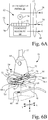
- interventional medical device 18 has a distal tip 40 and a distal end portion 42 extending proximally from the distal tip 40.
- a tracking element 44 i.e., a wire electrical tracking coil
- the term "near" is a range of zero to 2 centimeters (cm)
- the extent of distal end portion 42 is in a range of 1 millimeter (mm) to 3 cm.
- Tracking element 44 allows the location of interventional medical device 18 to be known relative to ultrasound probe 16, as more fully described below.
- Tracking element 44 is configured to generate tip location data defining five degrees of freedom based on the EM locator field 36 generated by EM field generator 12.
- the five degrees of freedom are the X-axis, Y-axis, Z-axis, pitch, and yaw.
- a sixth degree of freedom, i.e., roll, may be also included, if desired.
- Tracking element 44 of interventional medical device 18 is communicatively coupled to processor circuit 24 of ultrasound console 14 via electrical cable 34, serving as a communication link 46 between processor circuit 24 and tracking element 44.
- “communications link” refers to an electrical transmission of data, i.e., information, and/or electrical power signals, over a wired or wireless communication medium.
- the communication link 46 provided by electrical cable 34 is a multi-conductor electrical cable that physically connects tracking element 44 to the ultrasound console 14, and in turn to processor circuit 24.
- communication link 46 may be in the form of a short range wireless connection, such as Bluetooth, via a Bluetooth dongle 48 attached to interventional medical device 18.
- the Bluetooth dongle 48 is configured as a Bluetooth transmitter using Bluetooth protocol, and a corresponding Bluetooth receiver is connected to processor circuit 24.
- Bluetooth dongle 48 communicates tracking information from tracking element 44, and other information associated with interventional medical device 18, such as an operating state, to processor circuit 24 of ultrasound imaging system 10.
- Bluetooth dongle 48 may be used to provide power to the EM tracking components incorporated into interventional medical device 18, in the case where the EM tracking component is an active circuit requiring a power source.
- Bluetooth dongle 48 may be disposable, and included with each interventional medical device 18. Alternatively, Bluetooth dongle 48 may be reusable. Sterility requirements for the reusable dongle are addressed by placing the sterilized dongle in a sterile bag through which a sterile connection to interventional medical device 18 is made.
- ultrasound probe 16 includes a probe housing 50 having a handle portion 52 joined with a head portion 54.
- handle portion 52 has an extent that is generally perpendicular (range of + 5 degrees) to the extent of head portion 54.
- Ultrasound probe 16 is communicatively coupled to processor circuit 24 of ultrasound console 14 via electrical cable 17, which may be a wired or a wireless connection.
- electrical cable 17 is depicted as a multi-conductor electrical cable that physically connects ultrasound probe 16 to ultrasound console 14, and includes a communication link 56, a communication link 58, and a communication link 60, each formed with wire conductors.
- communication link 56, communication link 58, and communication link 60 may be in the form of a (short range) wireless connection, such as Bluetooth.
- Portions of the processor circuit 24 could also be embedded in the ultrasound probe to analyze or process the received/transmitted signal to the ultrasound emitting element. The analyzed or processed signal is then transmitted back to the console via electrical cable.
- ultrasound probe 16 includes an ultrasound transducer mechanism 62 and a tracking element 64. Both ultrasound transducer mechanism 62 and tracking element 64 are mounted to probe housing 50 (see also Fig. 5A ), and may be contained within probe housing 50, which may be formed from plastic. Also, tracking element 64 may be embedded in the plastic of probe housing 50. Ultrasound transducer mechanism 62 is communicatively coupled to processor circuit 24 via communication links 56 and 58.
- ultrasound transducer mechanism 62 has an active ultrasound transducer array 66 configured to generate two-dimensional ultrasound slice data representing a two-dimensional ultrasound imaging slice 67 at any of a plurality of discrete imaging locations within a three-dimensional imaging volume 68 associated with head portion 54 of ultrasound probe 16.
- the three-dimensional imaging volume 68 is defined by a depth 68-1 of penetration of the ultrasound emission in the direction of the z-axis, a width 68-2 of ultrasound emission in the x-axis, and an ultrasound transducer scan extent 68-3 along the y-axis.
- Active ultrasound transducer array 66 may be, for example, a one-dimensional transducer array in the form of a linear ultrasound transducer array, or alternatively, may be in the form of a convex or concave ultrasound transducer array.
- one-dimensional transducer array is an array of ultrasound transducer elements arranged in a single row, wherein the row may be linear or curved.
- Active ultrasound transducer array 66 is communicatively coupled to processor circuit 24 via communication link 58, and supplies two-dimensional ultrasound data to processor circuit 24 via communication link 58. Automatically, or alternatively based on a user input at graphical user interface 22, processor circuit 24 executes program instructions to store the two-dimensional ultrasound data in mass storage provided in non-transitory electronic memory 24-2.
- processor circuit 24 includes circuitry, or alternatively executes program instructions, to convert the two-dimensional ultrasound data to a form for viewing as a two-dimensional ultrasound image 69 on display screen 28 of graphical user interface 22.
- the two-dimensional ultrasound image 69 depicts interventional medical device 18 having tracking element 44 located in a blood vessel BV, and depicts distal tip 40 of distal end portion 42 of interventional medical device 18 engaged with an intravascular occlusion IC.
- tracking element 64 i.e., a wire electrical tracking coil
- Tracking element 64 is configured to generate probe location data defining six degrees of freedom based on the EM locator field 36 generated by EM field generator 12.
- the six degrees of freedom are the X-axis, Y-axis, Z-axis, pitch, yaw, and roll.
- Tracking element 64 is communicatively coupled to processor circuit 24 via communication link 60, and supplies probe location data to processor circuit 24 via communication link 60. Tracking element 64 allows for the determination of the location of ultrasound probe 16 within detection volume 38 as depicted in Fig. 1 , wherein detection volume 38 is considerably larger (more than 20 times larger) than the three-dimensional imaging volume 68 of ultrasound probe 16 depicted in Fig. 5A .
- active ultrasound transducer array 66 of ultrasound transducer mechanism 62 of ultrasound probe 16 may incorporate a movable one-dimensional (1D) transducer array, as in the embodiment depicted in Figs. 6A and 6B .
- active ultrasound transducer array 66 of ultrasound transducer mechanism 62 of ultrasound probe 16 may be in the form of a selectable portion of a two-dimensional (2D) matrix transducer array.
- active ultrasound transducer array 66 is physically movable relative to the probe housing 50, i.e., is dynamically positioned within probe housing 50, in order to capture ultrasound images of locations within the three-dimensional imaging volume 68 (diagrammatically illustrated cube volume, for convenience) beneath ultrasound probe 16.
- ultrasound transducer mechanism 62 includes a one-dimensional (1D) ultrasound transducer array 70, a carriage 72, and a stepper motor 74.
- one-dimensional ultrasound transducer array 70 serves as the active ultrasound transducer array 66.
- the one-dimensional ultrasound transducer array 70 has a row of a plurality of discrete ultrasound transducer elements.
- Carriage 72 is connected to one-dimensional ultrasound transducer array 70, such that one-dimensional ultrasound transducer array 70 moves in unison with carriage 72.
- Carriage 72 converts a rotation of a rotatable shaft 74-1 of stepper motor 74 into a linear translation of carriage 72, and in turn, into a linear translation of one-dimensional ultrasound transducer array 70 relative to head portion 54 of probe housing 50, in a determined one of two translation directions D1, D2.
- Stepper motor 74 is operably connected (electrically and communicatively) to probe position control circuit 31 (see Fig. 2 ) via communication link 56 of electrical cable 17.
- probe position control circuit 31 is in the form of a motor control circuit, which converts the digital positioning signal supplied by processor circuit 24 into a stepper motor positioning signal, which may include multiple stepper motor control signals, and which are supplied by motor control circuit 76 to stepper motor 74 to command rotation of rotatable shaft 74-1 by an amount corresponding to the amount and position dictated by the digital positioning signal.
- the digital positioning signal and the stepper motor positioning signal may be referred to herein collectively as the "positioning signal", since the stepper motor positioning signal is a form change of the digital positioning signal, and the "positioning signal” is considered herein to have been generated by processor circuit 24.
- Carriage 72 converts the rotation of rotatable shaft 74-1 of stepper motor 74 into a linear translation of carriage 72, and in turn, moves one-dimensional ultrasound transducer array 70 relative to head portion 54 of probe housing 50 in a determined one of two translation directions D1, D2, to a location thus dictated by the digital positioning signal generated by processor circuit 24.
- the one-dimensional ultrasound transducer array 70 may be moved to a desired position relative to head portion 54 of probe housing 50.
- Fig. 6B shows an embodiment of carriage 72, wherein carriage 72 has an endless toothed belt 78 suspended between two longitudinally spaced idler gears/pulleys 80-1, 80-2.
- Rotatable shaft 74-1 of stepper motor 74 is connected to a drive gear 82.
- Drive gear 82 is drivably engaged with the teeth of endless toothed belt 78.
- One-dimensional ultrasound transducer array 70 is attached to the lower run 78-1 of endless toothed belt 78, and is movable along the longitudinal extent between the two longitudinally spaced idler gears/pulleys 80-1, 80-2.
- the arrangement of toothed belt 78 suspended between two longitudinally spaced idler gears/pulleys 80-1, 80-2 converts a rotation of the rotatable shaft 74-1 of the stepper motor 74 into a translation of the one-dimensional ultrasound transducer array 70 in a selectable one of the two translation directions D1, D2.
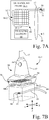
- an alternative ultrasound transducer mechanism 62-1 includes a two-dimensional (2D) ultrasound transducer array 84, and probe position control circuit 31 (see Fig. 2 ) is in the form of a matrix address circuit of the type used in addressing electronic memory.
- Two-dimensional ultrasound transducer array 84 has a plurality of columns 84-1 and a plurality of addressable rows 84-2 of discrete ultrasound transducer elements arranged in a matrix pattern.
- the two-dimensional ultrasound transducer array 84 may be a planar transducer arrangement, or alternatively may be a concave or convex arrangement.
- Two-dimensional ultrasound transducer array 84 is communicatively coupled to processor circuit 24 via communications link 58 to supply two-dimensional ultrasound data from two-dimensional ultrasound transducer array 84 to processor circuit 24.
- probe position control circuit 31 is electrically connected to processor circuit 24 to receive the digital positioning signal generated by processor circuit 24.
- probe position control circuit 31 operates as a matrix address circuit to convert the digital positioning signal supplied by processor circuit 24 into a row selection positioning signal which is supplied to two-dimensional (2D) ultrasound transducer array 84 via communications link 56 to dynamically select one row of the plurality of rows 84-2 of discrete ultrasound transducer elements as the active linear ultrasound transducer array 66.
- the row selection positioning signal corresponds to the position dictated by the digital positioning signal generated by processor circuit 24.
- the row selection positioning signal is a form change of the digital positioning signal
- the digital positioning signal and the row selection positioning signal may be referred to herein collectively as the "positioning signal”, and the "positioning signal” is considered herein to have been generated by processor circuit 24.
- Figs. 7A and 7B emulates the dynamic positioning of the one-dimensional ultrasound transducer array 70 discussed above with respect to Figs. 6A and 6B , and allows for similar control of where the ultrasound probe will image within the three-dimensional imaging volume 68 beneath the ultrasound probe (see Fig. 5A ).
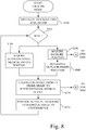
- ultrasound imaging system 10 provides a "lock-on" functionality, wherein the position of each of the ultrasound probe 16 and interventional medical device 18 are tracked, and the active ultrasound transducer array 66 in ultrasound probe 16 is dynamically positioned at a convergence of the tracking information, which is further described with reference to the flowchart of Fig. 8 .
- processor circuit 24 is communicatively coupled to each of the tracking element 44 of interventional medical device 18, tracking element 64 of ultrasound probe 16, ultrasound transducer mechanism 62 of ultrasound probe 16, and to the graphical user interface 22 having display screen 28.
- processor circuit 24 executes program instructions to determine the type of tracking elements that are associated with each of ultrasound probe 16 and interventional medical device 18, the communications rate between processor circuit 24 and each of ultrasound probe 16 and interventional medical device 18, the rate of data acquisition updating, and probe parameters.
- probe parameters may include, scan extent start point and end point, and the desired velocity of the movement of active ultrasound transducer array 66, with respect to the origin point 71 (see Fig. 5A ), defining the 0, 0, 0 location in the X, Y, and Z axes.
- the location of tracking elements of ultrasound probe 16 and interventional medical device 18 may be calibrated with respect to the 3D detection volume 38 defined by EM field generator 12 (see Fig. 1 ).
- WHILE defines the entry into a continuous loop to virtually converge the position of the ultrasound imaging plane of active ultrasound transducer array 66 of ultrasound probe 16 with the position of tracking element 44, and in turn distal tip 40, of interventional medical device 18.
- Processor circuit 24 remains in this continuous loop until the program execution is stopped.
- the current position of tracking element 44 of interventional medical device 18 is determined in relation to the 3D detection volume 38 defined by EM field generator 12.
- tracking element 44 of interventional medical device 18 generates tip location data as physical coordinates based on the EM locator field 36 generated by EM field generator 12, and provides the tip location data associated with the physical coordinates to processor circuit 24.
- step S106 in parallel to step S104, the current position of tracking element 64 of ultrasound (US) probe 16 is determined in relation to the 3D detection volume 38 defined by EM field generator 12.
- tracking element 64 of ultrasound probe 16 generates probe location data as physical coordinates based on the EM locator field 36 generated by EM field generator 12, and provides the probe location data associated with the physical coordinates to processor circuit 24.
- an ultrasound plane position (B-scan position) is determined based on the probe location data.
- processor circuit 24 executes program instructions to define a unit vector, i.e., the Z-axis at origin point 71 (0,0,0) of Fig. 5A , that is perpendicular to (e.g., points downwardly from) the surface of head portion 54 of ultrasound probe 16, wherein the unit vector initially lies on a current ultrasound image plane.
- Processor circuit 24 executes program instructions to virtually rotate the vector to be normal to the current ultrasound image plane.
- Processor circuit 24 then executes program instructions to rotate the normal vector about the Z-axis using the probe location data acquired at step S106, which corresponds to the orientation angle of ultrasound probe 16.
- the Equation 2 offset calculation gives the minimum, or perpendicular, distance from tracking element 44 of interventional medical device 18 to the ultrasound plane position, which is the distance (and direction) that ultrasound transducer mechanism 62 needs to move active ultrasound transducer array 66 so that there is a convergence (intersection) of the ultrasound position plane with the tracking element 44, and in turn distal tip 40, of interventional medical device 18.
- the calculation determines the offset used to achieve a convergence of the tip location data with the ultrasound plane position associated with the probe location data.
- ultrasound transducer mechanism 62 is driven to position active ultrasound transducer array 66 at the determined point of convergence as defined by the OFFSET calculated at step S110.
- processor circuit 24 executes program instructions to process the OFFSET to generate the positioning signal corresponding to the point of convergence, and the positioning signal is communicatively coupled to ultrasound transducer mechanism 62 to dynamically position active ultrasound transducer array 66 at a desired imaging location of the plurality of discrete imaging locations, so that the two-dimensional ultrasound slice data captured by active ultrasound transducer array 66 includes an image of at least the distal tip 40 of interventional medical device 18, so long as distal tip 40 of the interventional medical device 18 remains in the three-dimensional imaging volume 68 under the surface of the head portion of ultrasound probe 16.
- the positioning signal will culminate in stepper motor control signal that are supplied to stepper motor 74.
- the positioning signal will culminate in a row selection signal supplied to two-dimensional ultrasound transducer array 84.
- under or underlying with respect to ultrasound probe 16, means within the possible imaging view extent of ultrasound probe 16.
- step S102 "WHILE"
- WHILE WHILE
- FIG. 9 there is shown a flowchart describing the acquisition of ultrasound data concurrently with, i.e., during, the "lock-on" function described above with respect to Fig. 8 .
- ultrasound probe 16 is configured for acquisition of ultrasound data. For example, parameters such as the desired resolution, and emission strength of active ultrasound transducer array 66 to achieve a desired depth of penetration, may be set.
- ultrasound imaging system 10 is configured to collect a series of two-dimensional ultrasound imaging slices (ultrasound B-scan) data.
- ultrasound imaging system 10 is configured to collect a series of ultrasound B-scan data to form three-dimensional ultrasound volumetric data representing the three-dimensional imaging volume 68, from which C-scan data, or other plane oriented data, may be derived.
- WHILE defines the entry into a continuous loop for acquisition of ultrasound data with active ultrasound transducer array 66 of ultrasound probe 16.
- processor circuit 24 is configured to execute program instructions, or alternatively includes circuitry, to process two-dimensional ultrasound slice data generated by the active ultrasound transducer array 66 of ultrasound transducer mechanism 62 of ultrasound probe 16, and to generate the ultrasound image for display at display screen 28 of graphical user interface 22. Also, processor circuit 24 may execute program instructions to automatically store the two-dimensional ultrasound slice data in non-transitory electronic memory 24-2, and thus accumulate multiple image data sets of the location of interest. Alternatively, graphical user interface 22 may provide a user command to processor circuit 24 to store the two-dimensional ultrasound slice data in non-transitory electronic memory 24-2 on demand at the command from a user.
- a series of two-dimensional ultrasound imaging slices (ultrasound B-scan) data is collected and stored in non-transitory electronic memory 24-2.
- active ultrasound transducer array 66 is scanned along the Y-axis across all, or a selected portion, of the three-dimensional imaging volume 68 to take a detailed volumetric scan of the underlying area beneath head portion 54 of ultrasound probe 16, such that a series of ultrasound B-scan data representing the three-dimensional imaging volume is collected and stored in non-transitory electronic memory 24-2.
- step S202 "WHILE"
- ultrasound imaging system 10 is able to dynamically position active ultrasound transducer array 66 to converge at a desired imaging location of the plurality of discrete imaging locations in the three-dimensional imaging volume 68 so that the two-dimensional ultrasound slice data includes an image of at least the distal tip 40 of interventional medical device 18 in generating the ultrasound image displayed on display screen 28.
- a motion indicator 88 located on at least one of the ultrasound probe 16 and the display screen 28 of graphical user interface 22 (see also Fig. 2 ) is provided to guide the user to an acceptable placement of ultrasound probe 16 relative to the tracked interventional medical device 18.
- Motion indicator 88 is operably coupled to processor 24, and may be in the form of directional arrows that may be selectively illuminated by processor circuit 24 so as to guide the user to an acceptable placement of ultrasound probe 16 relative to the tracked interventional medical device 18.
- processor circuit 24 executes program logic to determine whether tracking element 44 of interventional medical device 18 is outside the three-dimensional imaging volume 68, and thus is outside the imageable range of ultrasound probe 16.
- processor circuit 24 executes program instructions to determine whether the distal tip 40 of the interventional medical device 18 is presently located outside the three-dimensional imaging volume 68.
- processor circuit 24 of ultrasound imaging system 10 further executes program instructions to generate a visual prompt at motion indicator 88 to prompt the user to move head portion 54 of ultrasound probe 16 in a particular direction to a general location such that tracking element 44, and thus distal tip 40, of interventional medical device 18 resides in the three-dimensional imaging volume 68 under ultrasound probe 16, thereby permitting the active ultrasound transducer array 66 of ultrasound probe 16 to automatically capture ultrasound image data containing the tracking element 44 and distal tip 40 of interventional medical device 18 for display on display screen 28.
- ultrasound imaging system 10 uses ultrasound imaging system 10 to converge on a two-dimensional ultrasound image slice that includes the underlying interventional medical device 18, even if ultrasound probe 16 is not placed directly over tracking element 44/distal tip 40 of interventional medical device 18.
- the position of the active ultrasound transducer array 66 of ultrasound probe 16 is dynamically adjusted in near real time, limited by data acquisition and processing speed, which allows ultrasound imaging system 10 to adapt to small changes in position of ultrasound probe 16, the position of the tracking element 44 of interventional medical device 18, and/or the patient position, such that an ultrasound image of the underlying interventional medical device 18 is maintained within view of ultrasound probe 16.
- positioning prompts in the form of motion indicator 88 are again generated and used to prompt the user to move ultrasound probe 16 in a direction that allows ultrasound imaging system 10 to again converge on, and display, an ultrasound image of the underlying interventional medical device 18.
- Ultrasound imaging system 10 also may be operated in a three-dimensional (3D) high resolution scan imaging mode, with reference to step S204 of Fig. 9 .
- the ultrasound probe 16 in the three-dimensional (3D) high resolution imaging mode the ultrasound probe 16 is held in a fixed position over an area of interest, and the active ultrasound transducer array 66 is scanned along the Y-axis across all, or a selected portion, of the three-dimensional imaging volume 68 to take a detailed volumetric scan of the underlying area beneath head portion 54 of ultrasound probe 16.
- Ultrasound probe 16 may be held in the fixed position by the hand of the user. Metadata containing the position location from each two-dimensional slice obtained in the high resolution mode is further used to identify images taken from the same point in space, and subsequently used for image integration processing.
- processor circuit 24 of ultrasound console 14 is configured to execute program instructions to generate a scanning signal that is supplied to ultrasound transducer mechanism 62 to scan active ultrasound transducer array 66 over at least a portion of the three-dimensional imaging volume 68.
- the active ultrasound transducer array 66 is repeatedly actuated during the scan to generate a plurality, i.e., a series, of sequential two-dimensional ultrasound slices, which are stored in memory 24-2, and combined to form the 3D ultrasound volumetric data from which a three-dimensional (3D) high resolution ultrasound image is formed and displayed on display screen 28 of graphical user interface 22 (see also Fig. 2 ).
- the quality of the high resolution 3D images may be improved by generating a composite ultrasound image of the location of interest. Because the location of the ultrasound probe 16 is known by processor circuit 24, multiple sets of 2D or 3D, ultrasound images of a particular location in the three-dimensional imaging volume 68 underlying, e.g., perpendicular to, the surface of the head portion 54 of ultrasound probe 16 may be taken, and stored in non-transitory electronic memory 24-2, from which a compound composite ultrasound image may be generated from the multiple sets of 2D, or 3D, ultrasound images by summing together the multiple sets of ultrasound images of the same location.
- processor circuit 24 is configured to execute program instructions to operate the active ultrasound transducer array 66 to generate multiple sets of ultrasound image data that includes metadata corresponding to a particular location, i.e., metadata describing the location of the scan within the three-dimensional volume 68, and save the multiple sets in non-transitory electronic memory 24-2.
- Processor circuit 24 is further configured to execute program instructions to sum the multiple sets of ultrasound image data to generate composite (compound) ultrasound image data, which is then stored in non-transitory memory 24-2 and/or is displayed on display screen 28 of graphical user interface 22.
- the quality of the high resolution 3D images also may be improved by tracking the position of the patient P in relation to the position of ultrasound probe 16 to reduce motion artifacts in the 3D images.
- a third EM tracking element 90 i.e., a wire electrical tracking coil
- Tracking element 90 is communicatively coupled to processor circuit 24 of ultrasound console 14 by a communication link 92, such as a wired or wireless connection.
- Tracking element 90 when energized by electromagnetic (EM) field generator 12, generates three-axis patient location data, which is supplied via communications link 92 to processor circuit 24.
- EM electromagnetic
- Processor circuit 24 processes the three-axis patient location data to further adjust the position of the active ultrasound transducer array 66 of ultrasound probe 16 in response to any motion of the patient.
- tracking element 90 allows for the position of the patient to be known, which in turn allows ultrasound imaging system 10 to adjust the position of the active ultrasound transducer array 66 of ultrasound probe 16 to any motion created by the patient.
- Ultrasound imaging system 10 also may be operated to render and display one or more synthetic (user chosen) scan planes.
- a plurality, i.e., a series, of sequential two-dimensional ultrasound slices may be generated and combined to generate 3D ultrasound volumetric data defining a three-dimensional imaging volume.
- the user may select for rendering and display one or more synthetic (user chosen) scan planes, such as a coronal scan plane 98 and an axial (sagittal) scan plane 100.
- the user may define, using user controls 96, a desired synthetic plane orientation with respect to the 3D ultrasound volumetric data associated with three-dimensional ultrasound image 94.
- processor circuit 24 of ultrasound imaging system 10 executes program instructions to identify within the 3D ultrasound volumetric data of three-dimensional ultrasound image 94 the image data associated with the desired synthetic plane orientation.
- the desired synthetic plane may pass through multiple two-dimensional image data slices in the 3D ultrasound volumetric data.
- the desired one or more synthetic (user chosen) scan planes may be rendered and displayed on display screen 28 of graphical user interface 22 within the generated three-dimensional ultrasound image 94 as shown in Fig. 11 , or as standalone two-dimensional images.
- Various views such as those associated with the sagittal plane, the transverse plane, and the coronal plane, may be visualized, and a slice from one or more, or all, of the planes, as defined by the location of the tracked device(s), e.g., tracking element 44 of interventional medical device 18 and/or tracking element 64 of ultrasound probe 16, can be displayed, individually or as a group.
- the tracked device(s) e.g., tracking element 44 of interventional medical device 18 and/or tracking element 64 of ultrasound probe 16
- scan planes that do not exist at 90 degrees from each other could also be defined and selected by the user. Additionally, the user defined scan planes may not be planar, and may follow a curved path.
- Another aspect of the present invention provides for a focusing of the three-dimensional imaging volume around a determined region of interest, i.e., the region around the location of tracking element 44 of interventional medical device 18, by reducing the scan extent along the Y-axis (see Fig. 5A ), thus reducing the amount of three-dimensional ultrasound volumetric data required to adequately view the region surrounding interventional medical device 18.
- the scan extent of active ultrasound transducer array 66 along the Y-axis is reduced, i.e., focused, to that of most interest, thus reducing scanning time and the amount of data required to adequately represent the three-dimensional volume of interest.
- processor circuit 24 executes program instructions to determine a region of interest in the three-dimensional ultrasound volumetric data defining the three-dimensional imaging volume 68.
- Processor circuit 24 also executes program instructions to reduce the scan range of the active ultrasound transducer array 66 of the ultrasound transducer mechanism 62 along the Y-axis for acquisition of subsequent three-dimensional ultrasound volumetric data at the region of interest from that of the scan range of the previous scan, so as to reduce the amount of acquired three-dimensional ultrasound volumetric data from that of the prior scan.
- user controls 96 of graphical user interface 22 may include one or more slice selection sliders 102, such as a coronal slider 102-1 and a sagittal slider 102-2, to provide a sequential variation from an automatically, or manually, selected two-dimensional ultrasound image slice being displayed.
- slice selection sliders 102 such as a coronal slider 102-1 and a sagittal slider 102-2
- a plurality, i.e., a series, of sequential two-dimensional ultrasound B-scan imaging slices 67 may be generated and combined to generate 3D ultrasound volumetric data defining a three-dimensional imaging volume 68.
- a desired two-dimensional ultrasound image slice on a desired imaging plane may be generated from the 3D ultrasound volumetric data that includes a particular region of interest, such as distal tip 40 of interventional medical device 18.
- the desired two-dimensional ultrasound image slice may be in an imaging plane different from that of the native B-scan imaging plane of the sequential two-dimensional ultrasound imaging slices 67 that when combined form the 3D ultrasound volumetric data defining the three-dimensional imaging volume 68.
- slice selection sliders 102 permit the user to select a slice in each of one or more imaging planes for display, if desired, wherein the selected two-dimensional ultrasound image slice may intersect, or lie on either side of, the two-dimensional ultrasound image slice that was automatically, or manually, selected.
- the slice selection sliders 102 are configured to provide a sequential parallel variation from the initially selected two-dimensional ultrasound image slice to manually select a second two-dimensional ultrasound image slice parallel to the initially selected two-dimensional ultrasound image, wherein the second two-dimensional ultrasound image slice lies on either side of the initially selected two-dimensional ultrasound image slice.
- Fig. 12 is a pictorial representation at graphical user interface 22 depicting a selection of a sagittal plane slice 104 extending through a series of two-dimensional ultrasound image slices 67 in the three-dimensional imaging volume 68 at sagittal slice location 270.
- sagittal slider 102-2 By manipulation of sagittal slider 102-2 using one of the up-down arrows, sagittal slice location 271, or others 1-269 or 272-560, parallel to the sagittal slice location 270 may be selected for display.
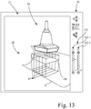
- Fig. 13 is a pictorial representation depicting a selection of a coronal plane slice 106 extending through a series of two-dimensional ultrasound image slices 67 in a three-dimensional imaging volume 68 at coronal slice location 150.
- coronal slider 102-1 By manipulation of coronal slider 102-1 using one of the up-down arrows, coronal slice location 151, or others 1-149 or 152-560, may be selected for display.
- FIG. 14 there is shown a flowchart describing the generation of a 3D ultrasound image as a set of three orthogonal ultrasound images.
- ultrasound imaging system 10 is initialized for rendering a 3D ultrasound image as a set of three orthogonal images, such as setting up processor circuit 24 and graphical user interface 22 for construction of 3D models.
- WHILE defines the entry into a continuous loop for generation and updating of the displayed 3D ultrasound image.
- an ultrasound (US) volume transform node is updated based on the position of ultrasound probe 16, as determined at step S106 of Fig. 8 .
- processor circuit 24 executes program instructions to move the 3D model of the three-dimensional imaging volume 68 to match the current position of ultrasound probe 16.
- processor circuit 24 executes program instructions to choose a two-dimensional ultrasound imaging slice 67 (B-scan) from a C-scan data slice that includes the tracking element 44, and in turn the distal tip 40, of interventional medical device 18.
- B-scan two-dimensional ultrasound imaging slice 67
- processor circuit 24 executes program instructions to generate 3D display data representative of three orthogonal images in a virtual 3D environment associated with the three-dimensional imaging volume 68 matched to the current position of ultrasound probe 16.
- Processor circuit 24 sends the 3D display data to user interface 22 for display on display screen 28 as three orthogonal images that include the tracking element 44, and in turn the distal tip 40, of interventional medical device 18.
- Figs. 15A, 15B , 15C and 16 there is described below a patient oriented imaging window mode.
- that which was rendered as "up” on the ultrasound display screen followed the orientation of the ultrasound probe.
- the orientation of the displayed ultrasound image is true to the orientation of the patient, regardless of the actual orientation of the ultrasound probe.
- Fig. 15A shows a diagrammatic illustration of ultrasound probe 16 taking a two-dimensional ultrasound imaging slice 67 of a portion of a leg L of a patient.
- Fig. 15B is a diagrammatic illustration of graphical user interface 22 having a patient oriented imaging window 108 depicting a patient oriented virtual environment on display screen 28 of graphical user interface 22, wherein the location and orientation of the acquired ultrasound image data is rendered on the display screen 28 to correspond to the orientation of the patient P, wherein the orientation and location of where the ultrasound image is being acquired relative to a position of the patient P is indicated and communicated to the clinician via use of the virtual environment.
- Fig. 15B shows a diagrammatic illustration of graphical user interface 22 having patient oriented imaging window 108 including an image of leg L, rendered as an actual image of patient leg L or as a computer generated virtual rendering, and including a virtual rendering of ultrasound probe 16 and two-dimensional ultrasound imaging slice 67 that is generated by ultrasound probe 16.
- a secondary imaging window 110 including a computer generated virtual rendering, i.e., a graphic, of the orientation of the body of patient P, as well as an UP arrow indicating the orientation of the UP relative to the patient.
- the display of the ultrasound image on display screen 28 of graphical user interface 22 may be adjusted such that a vertical "top” 67-1 of the acquired ultrasound image data of two-dimensional ultrasound imaging slice 67, or the vertical top of the acquired volumetric data in 3D data acquisition, is always rendered as "UP" on display screen 28 relative to the position of the patient P, and regardless of the actual orientation of ultrasound probe 16 relative to the patient. In other words, even if the actual orientation of ultrasound probe 16 is changed relative to the position of the leg L from that depicted in Fig.
- the orientation of the ultrasound image on display screen 28 of graphical user interface 22 remains as depicted in Fig. 15C .
- features of the displayed image such as the upper blood vessel 107-1, and the lower-left blood vessel 107-2, are always displayed in the correct orientation relative to the patient P.
- FIG. 15D depicts the ultrasound image generated in Fig. 15A as it would be rendered in accordance with the prior art, wherein the orientation of the acquired ultrasound image data rendered on the display screen does not correspond to the orientation of the patient.
- the image is rendered on the display screen wherein the ultrasound probe head is in a virtual position at the top of the display screen and the bottom on the display screen always corresponds to the distal extent of the generated ultrasound image. More particularly, with the ultrasound probe oriented as depicted in Figs. 15A and 15B , the prior art rendered ultrasound image would position the upper blood vessel 107-1 and the lower-left blood vessel 107-2 on the display screen as shown in Fig.
- the displayed image no longer corresponds to the orientation of the patient P. Rather, as shown in Fig. 15D , using arrow 112 to designate the true "up" orientation, the prior art ultrasound image is actually rendered to face toward the left on the display screen. Accordingly, in the prior art, the ultrasound technician was required to mentally associate the orientation of the displayed image with that of the actual orientation of the patient.
- the patient oriented imaging window aspect of the present invention described above with respect to Figs. 15A, 15B and 15C , generates a virtual environment that aids a clinician, including a person not experienced in ultrasound imaging, in successful image acquisition.
- Fig. 16 is a flowchart of a patient oriented imaging window mode, i.e., a virtual environment imaging mode, associated with the generation of the patient oriented imaging window as depicted above with respect to Figs. 15A, 15B and 15C .
- a patient oriented imaging window mode i.e., a virtual environment imaging mode
- ultrasound imaging system 10 is initialized for rendering a 3D ultrasound image, such as setting up processor circuit 24 and graphical user interface 22 for construction of 3D models, initializing a camera video data transfer, and configuring appropriate patient lighting for video.
- WHILE defines the entry into a continuous loop for generation and updating of the displayed patient oriented imaging window 108 as depicted in Figs. 15B and 15C .
- an ultrasound (US) volume transform node is updated based on the position of ultrasound probe 16, as determined at step S106 of Fig. 8 .
- processor circuit 24 executes program instructions to move the 3D model of the three-dimensional imaging volume 68 (see Fig. 5A ) to match the current position of ultrasound probe 16.
- an ultrasound (US) image transform node is updated based on the calculated OFFSET from step S110 of Fig. 8 .
- processor circuit 24 executes program instructions to update the ultrasound image transform node by moving a 3D model of the three-dimensional ultrasound imaging data to match the current two-dimensional ultrasound imaging slice 67 (B-scan) acquired from ultrasound probe 16.
- processor circuit 24 executes program instructions to display the two-dimensional ultrasound imaging slice 67 (B-scan) in a 3-D environment in the patient oriented imaging window 108, such that the vertical "top” 67-1 of the acquired ultrasound image data of two-dimensional ultrasound imaging slice 67, or the vertical top of the acquired volumetric data in 3D data acquisition, is always rendered as "up” on display screen 28 relative to the position of the patient, and regardless of the actual orientation of ultrasound probe 16 relative to the patient.
- step 402 "WHILE"
- this offset, or depth information can further be used to dynamically control some of the ultrasound imaging settings in near real time, as identified below. This allows the system to optimize the image quality settings such that the best image of the interventional medical device 18 is displayed to the user at display screen 28.
- the ultrasound imaging settings that may be dynamically controlled because the z-axis offset from the ultrasound probe 16 can be calculated may include:
Landscapes
- Health & Medical Sciences (AREA)
- Life Sciences & Earth Sciences (AREA)
- Engineering & Computer Science (AREA)
- Medical Informatics (AREA)
- Surgery (AREA)
- Pathology (AREA)
- Radiology & Medical Imaging (AREA)
- Biophysics (AREA)
- Biomedical Technology (AREA)
- Heart & Thoracic Surgery (AREA)
- Physics & Mathematics (AREA)
- Molecular Biology (AREA)
- Nuclear Medicine, Radiotherapy & Molecular Imaging (AREA)
- Animal Behavior & Ethology (AREA)
- General Health & Medical Sciences (AREA)
- Public Health (AREA)
- Veterinary Medicine (AREA)
- Computer Vision & Pattern Recognition (AREA)
- Computer Graphics (AREA)
- General Engineering & Computer Science (AREA)
- Ultra Sonic Daignosis Equipment (AREA)
Claims (15)
- Ultraschallbildgebungssystem (10), umfassend:einen elektromagnetischen (EM-) Feldgenerator (12), der dazu konfiguriert ist, ein EM-Lokalisierungsfeld (36) zu generieren;eine medizinische Interventionsvorrichtung (18), die durch einen länglichen Körper definiert ist, der eine distale Spitze (40) und einen distalen Endabschnitt (42) aufweist, der sich proximal von der distalen Spitze erstreckt, und die ein erstes Nachführungselement (44), das in dem distalen Endabschnitt der medizinischen Interventionsvorrichtung angebracht ist, aufweist, wobei das erste Nachführungselement dazu konfiguriert ist, Lokalisierungsdaten der Spitze auf der Grundlage des EM-Lokalisierungsfeldes zu generieren;eine Ultraschallsonde (16), die ein Sondengehäuse (50), einen Ultraschallwandlermechanismus (62) und ein zweites Nachführungselement (64) aufweist, wobei das Sondengehäuse einen Griffabschnitt (52) und einen Kopfabschnitt (54) aufweist, wobei der Ultraschallwandlermechanismus und das zweite Nachführungselement an dem Sondengehäuse angebracht sind, wobei der Ultraschallwandlermechanismus eine aktive Ultraschallwandleranordnung (66) aufweist, die dazu konfiguriert ist, zweidimensionale Ultraschallschnittdaten an einem von einer Vielzahl von diskreten Bildgebungslokalisierungen innerhalb eines dreidimensionalen Bildgebungsvolumens (68) zu generieren, das dem Kopfabschnitt zugeordnet ist, wobei das zweite Nachführungselement dazu konfiguriert ist, Lokalisierungsdaten der Sonde auf der Grundlage des EM-Lokalisierungsfeldes zu generieren;einen Anzeigebildschirm (28), der dazu konfiguriert ist, ein Ultraschallbild in einer virtuellen 3D-Umgebung anzuzeigen, die es ermöglicht, dem Benutzer die Lokalisierung und die Ausrichtung des Ultraschallbildes zu beschreiben; undeine Prozessorschaltung (24), die kommunikativ mit dem ersten Nachführungselement, dem zweiten Nachführungselement, dem Ultraschallwandlermechanismus und dem Anzeigebildschirm gekoppelt ist, wobei die Prozessorschaltung dazu konfiguriert ist, Programmanweisungen zum Verarbeiten der zweidimensionalen Ultraschallschnittdaten auszuführen, um das Ultraschallbild zur Anzeige an dem Anzeigebildschirm zu generieren, unddadurch gekennzeichnet, dass die Prozessorschaltung dazu konfiguriert ist, ein Positionierungssignal auf der Grundlage der Lokalisierungsdaten der Spitze und der Lokalisierungsdaten der Sonde zu generieren, um die aktive Ultraschallwandleranordnung an einer gewünschten Bildgebungslokalisierung der Vielzahl von diskreten Bildgebungslokalisierungen dynamisch zu positionieren, sodass die zweidimensionalen Ultraschallschnittdaten mindestens die distale Spitze der medizinischen Interventionsvorrichtung einschließen, solange eine Lokalisierung der distalen Spitze der medizinischen Interventionsvorrichtung in dem dreidimensionalen Bildgebungsvolumen verbleibt.
- Ultraschall-Bildgebungssystem nach Anspruch 1, wobei eine Relativbewegung der Ultraschallsonde und der distalen Spitze der medizinischen Interventionsvorrichtung in einer Bewegung der distalen Spitze der medizinischen Interventionsvorrichtung in Bezug auf das dreidimensionale Bildgebungsvolumen resultiert, wobei das System weiter umfasst:einen Bewegungsanzeiger (88), der sich auf mindestens einem von der Ultraschallsonde und dem Anzeigebildschirm befindet; unddie Prozessorschaltung, die betriebsfähig mit dem Bewegungsanzeiger gekoppelt ist, wobei, wenn die Prozessorschaltung bestimmt, dass sich die distale Spitze der medizinischen Interventionsvorrichtung gegenwärtig außerhalb des dreidimensionalen Bildgebungsvolumens befindet, die Prozessorschaltung weiter Programmanweisungen ausführt, um eine visuelle Aufforderung an dem Bewegungsanzeiger zu generieren, um den Benutzer aufzufordern, den Kopfabschnitt der Ultraschallsonde in einer bestimmten Richtung zu einer allgemeinen Lokalisierung zu bewegen, sodass die distale Spitze der medizinischen Interventionsvorrichtung in dem dreidimensionalen Bildgebungsvolumen liegt, wobei der Ultraschallwandlermechanismus einschließt:eine Bewegungseinheit zum Durchführen einer linearen Bewegung, vorzugsweise einen Schlitten (72), der dazu konfiguriert ist, eine Umwandlung von einer Rotation in eine lineare Translation zu bewirken;eine eindimensionale Ultraschallwandleranordnung (70) als die aktive Ultraschallwandleranordnung, wobei die eindimensionale Ultraschallwandleranordnung für eine mit der Bewegungseinheit übereinstimmende Bewegung mit der Bewegungseinheit verbunden ist;vorzugsweise weiter einen Schrittmotor (74) einschließend, der eine drehbare Welle (74-1) aufweist, wobei der Schrittmotor betriebsfähig mit der Prozessorschaltung verbunden ist, um die drehbare Welle auf der Grundlage des von der Prozessorschaltung generierten Positionierungssignals zu drehen, wobei die drehbare Welle antriebsmäßig mit dem Schlitten gekoppelt ist, wobei der Schlitten eine Rotation der drehbaren Welle des Schrittmotors in eine Translation der eindimensionalen Ultraschallwandleranordnung umwandelt, um die eindimensionale Ultraschallwandleranordnung an einer durch das Positionierungssignal vorgegebenen Lokalisierung zu positionieren.
- Ultraschall-Bildgebungssystem nach Anspruch 1 oder 2, wobei der Wandlermechanismus eine zweidimensionale Ultraschallwandleranordnung (84) einschließt, die eine Vielzahl von Spalten (84-1) und einer Vielzahl von Reihen (84-2) von Ultraschallwandlerelementen aufweist, die in einem Matrixmuster angeordnet sind, wobei eine Reihe der Vielzahl von Reihen von diskreten Ultraschallwandlerelementen auf der Grundlage des Positionierungssignals als die aktive Ultraschallwandleranordnung ausgewählt ist.
- Ultraschall-Bildgebungssystem nach Anspruch 1, 2 oder 3, wobei die medizinische Interventionsvorrichtung eines von einem Katheter, einem Läsionsdurchgangskatheter, einem Führungsdraht, einer Schleuse, einem Angioplastieballon, einem Stenteinführungskatheter und einer Nadel ist.
- Ultraschall-Bildgebungssystem nach einem der Ansprüche 1 bis 4, wobei die Prozessorschaltung dazu konfiguriert ist, Programmanweisungen auszuführen, um die aktive Ultraschallwandleranordnung zu betreiben, um mehrere Sätze von Ultraschallbilddaten zu generieren, die Metadaten einschließen, die einer bestimmten Lokalisierung entsprechen, wobei die Prozessorschaltung dazu konfiguriert ist, Programmanweisungen auszuführen, um die mehreren Sätze von Ultraschallbilddaten zu summieren, um zusammengesetzte Ultraschallbilddaten zu generieren, wobei das Ultraschall-Bildgebungssystem ein drittes Nachführungselement (90) umfasst, das zur Befestigung an einem Patienten konfiguriert ist, wobei, wenn das dritte Nachführungselement durch den EM-Feldgenerator erregt wird, das dritte Nachführungselement Sechsachsen-Patientenlokalisierungsdaten generiert, die der Prozessorschaltung zugeführt werden, wobei die Prozessorschaltung Programmanweisungen ausführt, um die Sechsachsen-Patientenlokalisierungsdaten zu verarbeiten und Lokalisierungsinformationen für von der aktiven Ultraschallwandleranordnung aufgenommene Bilder bekannten Positionen innerhalb eines 3D-Volumens zuzuweisen, das von dem dritten Nachführungselement referenziert ist.
- Ultraschall-Bildgebungssystem nach einem der Ansprüche 1-5, wobei die Prozessorschaltung dazu konfiguriert ist, Programmanweisungen auszuführen, um mindestens eine synthetische Abtastebene durch Definieren einer gewünschten Bildebene in den dreidimensionalen volumetrischen Ultraschalldaten zu rendern und anzuzeigen.
- Ultraschall-Bildgebungssystem nach Anspruch 6, wobei die gewünschte Bildebene eine von einer koronalen Abtastebene und einer axialen Abtastebene ist.
- Ultraschall-Bildgebungssystem nach Anspruch 6 oder 7, wobei die Prozessorschaltung dazu konfiguriert ist, Programmanweisungen auszuführen, um einen Bereich von Interesse in den dreidimensionalen volumetrischen Ultraschalldaten, die das dreidimensionale Bildgebungsvolumen definieren, zu bestimmen, und dazu konfiguriert ist, Programmanweisungen auszuführen, um den Abtastbereich der aktiven Ultraschallwandleranordnung des Ultraschallwandlermechanismus zur Erfassung von nachfolgenden dreidimensionalen volumetrischen Ultraschalldaten in dem Bereich von Interesse von dem des Abtastbereichs der vorherigen Abtastung zu reduzieren.
- Ultraschall-Bildgebungssystem nach Anspruch 6, 7 oder 8, wobei die Prozessorschaltung dazu konfiguriert ist, Programmanweisungen auszuführen, um einen ersten zweidimensionalen Ultraschallbildschnitt aus einer Reihe von zweidimensionalen Ultraschallbildschnitten in den dreidimensionalen volumetrischen Ultraschalldaten zu generieren, wobei der erste zweidimensionale Ultraschallbildschnitt einen bestimmten Bereich von Interesse einschließt und der erste zweidimensionale Ultraschallbildschnitt in einer ersten Bildgebungsebene liegt, die sich von der der Bildgebungsebene der Reihe von zweidimensionalen Ultraschallbildschnitten unterscheidet, und weiter eine grafische Benutzerschnittstelle (22) umfasst, die kommunikativ mit der Prozessorschaltung gekoppelt ist, wobei die grafische Benutzerschnittstelle mindestens einen Schnittauswahlschieber (102) aufweist, der dazu konfiguriert ist, eine sequentielle parallele Variation von dem ersten zweidimensionalen Ultraschallbildschnitt bereitzustellen, um manuell einen zu dem ersten zweidimensionalen Ultraschallbild parallelen zweiten zweidimensionalen Ultraschallbildschnitt auszuwählen, wobei der zweite zweidimensionale Ultraschallbildschnitt auf einer von beiden Seiten des ersten zweidimensionalen Ultraschallbildschnitts liegt.
- Ultraschallsonde, die zur Verwendung mit dem System nach einem der Ansprüche 1 bis 9 angepasst ist.
- Verfahren zum Betreiben eines Ultraschall-Bildgebungssystems (10), umfassend:Erfassen einer Position eines ersten Nachführungselements (44), das einer medizinischen Interventionsvorrichtung (18) zugeordnet ist;Erfassen einer Position eines zweiten Nachführungselements (64), das einer Ultraschallsonde (16) zugeordnet ist,Bestimmen einer Position einer Ultraschall-Bildgebungsebene der Ultraschallsonde auf der Grundlage der Position des zweiten Nachführungselements;Bestimmen eines Versatzabstandes zwischen der Position des ersten Nachführungselements der medizinischen Interventionsvorrichtung und der Ultraschallebenenposition; undgekennzeichnet durchAnsteuern eines Ultraschallwandlermechanismus (62) zum Positionieren einer aktiven Ultraschallwandleranordnung (66) der Ultraschallsonde an einem bestimmten Konvergenzpunkt, wie er durch den Versatzabstand definiert wird.
- Verfahren nach Anspruch 11, wobei das erste Nachführungselement einer distalen Spitze (40) der medizinischen Interventionsvorrichtung zugeordnet ist, wobei das Verfahren umfasst:Bestimmen, ob sich die distale Spitze der medizinischen Interventionsvorrichtung gegenwärtig außerhalb eines dreidimensionalen Bildgebungsvolumens (68) befindet, das durch die Ultraschallsonde definiert wird; undGenerieren einer visuellen Aufforderung, um den Benutzer aufzufordern, einen Kopfabschnitt (54) der Ultraschallsonde in einer bestimmten Richtung zu einer allgemeinen Lokalisierung zu bewegen, sodass die distale Spitze der medizinischen Interventionsvorrichtung in dem dreidimensionalen Bildgebungsvolumen der Ultraschallsonde liegt.
- Verfahren nach Anspruch 11 oder 12, wobei der Ultraschallwandlermechanismus einschließt:eine Bewegungseinheit, die dazu angeordnet ist, eine lineare Bewegung auszuführen, vorzugsweise einen Schlitten (72), der dazu konfiguriert ist, eine Umwandlung von einer Rotation in eine lineare Translation zu bewirken;eine eindimensionale Ultraschallwandleranordnung (70) als die aktive Ultraschallwandleranordnung, wobei die eindimensionale Ultraschallwandleranordnung für eine gemeinsame Bewegung mit der Bewegungseinheit mit der Bewegungseinheit verbunden ist; undweiter vorzugsweise einen Schrittmotor (74) umfassend, der eine drehbare Welle (74-1) aufweist, die um einen dem Versatzabstand entsprechenden Drehbetrag gedreht wird, wobei die drehbare Welle antriebsmäßig mit dem Schlitten gekoppelt ist, wobei der Schlitten eine Rotation der drehbaren Welle des Schrittmotors in eine Translation der eindimensionalen Ultraschallwandleranordnung umwandelt, um die eindimensionale Ultraschallwandleranordnung an dem bestimmten Konvergenzpunkt zu positionieren.
- Verfahren nach Anspruch 11, 12 oder 13, wobei der Wandlermechanismus eine zweidimensionale Ultraschallwandleranordnung (84) einschließt, die eine Vielzahl von Spalten (84-1) und eine Vielzahl von Reihen (84-2) von Ultraschallwandlerelementen aufweist, die in einem Matrixmuster angeordnet sind, wobei eine Reihe der Vielzahl von Reihen von diskreten Ultraschallwandlerelementen auf der Grundlage des Versatzabstandes als die aktive Ultraschallwandleranordnung ausgewählt wird, um die aktive Ultraschallwandleranordnung an dem Konvergenzpunkt zu positionieren.
- Verfahren nach einem der Ansprüche 11 bis 14, umfassend:
Abtasten der aktiven Ultraschallwandleranordnung über mindestens einen Abschnitt des dreidimensionalen Bildgebungsvolumens; und wiederholtes Betätigen der aktiven Ultraschallwandleranordnung während des Abtastens, um eine Vielzahl von sequentiellen zweidimensionalen Ultraschalldatenschnitten zu generieren, die kombiniert werden, um dreidimensionale volumetrische Ultraschalldaten zu bilden, aus denen ein dreidimensionales Ultraschallbild generiert wird.
Applications Claiming Priority (2)
| Application Number | Priority Date | Filing Date | Title |
|---|---|---|---|
| US201462081275P | 2014-11-18 | 2014-11-18 | |
| PCT/US2015/018068 WO2016081023A1 (en) | 2014-11-18 | 2015-02-27 | Ultrasound imaging system having automatic image presentation |
Publications (2)
| Publication Number | Publication Date |
|---|---|
| EP3220828A1 EP3220828A1 (de) | 2017-09-27 |
| EP3220828B1 true EP3220828B1 (de) | 2021-12-22 |
Family
ID=52633725
Family Applications (1)
| Application Number | Title | Priority Date | Filing Date |
|---|---|---|---|
| EP15709069.7A Active EP3220828B1 (de) | 2014-11-18 | 2015-02-27 | Ultraschallbildgebungssystem mit automatischer bilddarstellung |
Country Status (4)
| Country | Link |
|---|---|
| US (2) | US10905396B2 (de) |
| EP (1) | EP3220828B1 (de) |
| CN (1) | CN106999146B (de) |
| WO (1) | WO2016081023A1 (de) |
Families Citing this family (54)
| Publication number | Priority date | Publication date | Assignee | Title |
|---|---|---|---|---|
| EP3220828B1 (de) | 2014-11-18 | 2021-12-22 | C.R. Bard, Inc. | Ultraschallbildgebungssystem mit automatischer bilddarstellung |
| WO2016081321A2 (en) | 2014-11-18 | 2016-05-26 | C.R. Bard, Inc. | Ultrasound imaging system having automatic image presentation |
| WO2016201006A1 (en) * | 2015-06-08 | 2016-12-15 | The Board Of Trustees Of The Leland Stanford Junior University | 3d ultrasound imaging, associated methods, devices, and systems |
| US20170203053A1 (en) * | 2016-01-19 | 2017-07-20 | Joseph Choate Burkett | Visual-Assisted Insertion Device |
| KR20170093632A (ko) * | 2016-02-05 | 2017-08-16 | 삼성전자주식회사 | 전자 장치 및 그의 동작 방법 |
| JP2019514652A (ja) * | 2016-04-27 | 2019-06-06 | ニュクス テクノロジーズ インコーポレイテッドNeux Technologies, Inc. | 電気治療処置 |
| WO2017202795A1 (en) * | 2016-05-23 | 2017-11-30 | Koninklijke Philips N.V. | Correcting probe induced deformation in an ultrasound fusing imaging system |
| CN107518917A (zh) * | 2017-08-21 | 2017-12-29 | 慈溪立声科技有限公司 | 一种可变形的手持三维超声探头及应用该探头的成像装置 |
| US20200367856A1 (en) * | 2017-08-22 | 2020-11-26 | C. R. Bard, Inc. | Ultrasound imaging probe for use in an ultrasound imaging system |
| US11911144B2 (en) | 2017-08-22 | 2024-02-27 | C. R. Bard, Inc. | Ultrasound imaging system and interventional medical device for use therewith |
| BR112020006146A8 (pt) | 2017-09-29 | 2023-03-21 | Bard Inc C R | Sistema e método para rastrear um objeto ultrassônico médico |
| EP3482691A1 (de) * | 2017-11-14 | 2019-05-15 | Koninklijke Philips N.V. | Katheter zur intracardialen echokardiographie mit mehreren wandlerarrays |
| CN111655156B (zh) * | 2017-12-19 | 2024-05-07 | 皇家飞利浦有限公司 | 组合基于图像的和惯性探头跟踪 |
| JP7299228B2 (ja) * | 2018-02-22 | 2023-06-27 | コーニンクレッカ フィリップス エヌ ヴェ | インターベンション医療デバイスの追跡 |
| EP3574841A1 (de) * | 2018-05-28 | 2019-12-04 | Koninklijke Philips N.V. | Ultraschallsondenpositionierungssystem |
| EP3809977A1 (de) * | 2018-06-22 | 2021-04-28 | Koninklijke Philips N.V. | Intravaskuläre ultraschallpositionserkennung |
| US10685439B2 (en) * | 2018-06-27 | 2020-06-16 | General Electric Company | Imaging system and method providing scalable resolution in multi-dimensional image data |
| WO2020038758A1 (en) * | 2018-08-22 | 2020-02-27 | Koninklijke Philips N.V. | 3d tracking of interventional medical devices |
| US11278312B2 (en) | 2018-08-29 | 2022-03-22 | Andrew J. Butki | Introducer assembly with reverberation feature to facilitate ultrasound guidance |
| US10966750B2 (en) | 2018-08-29 | 2021-04-06 | Andrew J. Butki | Needle assembly with reverberation feature to facilitate ultrasound guidance of the needle assembly |
| US12070354B2 (en) * | 2018-10-16 | 2024-08-27 | General Electric Company | Methods and system for detecting medical imaging scan planes using probe position feedback |
| CN113015489B (zh) * | 2018-10-25 | 2024-07-16 | 皇家飞利浦有限公司 | 用于在声学成像中估计介入设备的尖端的位置的系统和方法 |
| CN109701168B (zh) * | 2018-12-27 | 2022-03-18 | 成植温 | 一种伽马放射的肿瘤治疗系统 |
| US11272980B2 (en) * | 2019-04-04 | 2022-03-15 | Biosense Webster (Israel) Ltd. | Medical instrument with coagulation |
| CN111789630B (zh) * | 2019-04-08 | 2023-06-20 | 中慧医学成像有限公司 | 超声探头三维空间信息测量装置 |
| JP7171948B2 (ja) * | 2019-05-17 | 2022-11-15 | コーニンクレッカ フィリップス エヌ ヴェ | 対象の移動を追跡するための超音波システム及び方法 |
| WO2021028467A1 (en) * | 2019-08-15 | 2021-02-18 | Koninklijke Philips N.V. | Ultrasound-based device localization |
| CA3152545A1 (en) | 2019-09-20 | 2021-03-25 | Bard Access Systems, Inc. | Automatic vessel detection tools and methods |
| US12263033B2 (en) * | 2019-11-12 | 2025-04-01 | Biosense Webster (Israel) Ltd. | Historical ultrasound data for display of live location data |
| US20210196230A1 (en) * | 2019-12-29 | 2021-07-01 | Biosense Webster (Israel) Ltd. | Position registered sideview ultrasound (us) imager inserted into brain via trocar |
| US12329580B2 (en) * | 2020-03-05 | 2025-06-17 | Koninklijke Philips N.V. | Contextual multiplanar reconstruction of three-dimensional ultrasound imaging data and associated devices, systems, and methods |
| CN111436937B (zh) * | 2020-03-16 | 2024-06-11 | 北京东软医疗设备有限公司 | 导管/导丝跟踪方法、装置及扫描设备 |
| WO2022055887A1 (en) | 2020-09-08 | 2022-03-17 | Bard Access Systems, Inc. | Dynamically adjusting ultrasound-imaging systems and methods thereof |
| CN216257185U (zh) | 2020-09-10 | 2022-04-12 | 巴德阿克塞斯系统股份有限公司 | 超声探测器和超声系统 |
| CN112155595B (zh) * | 2020-10-10 | 2023-07-07 | 达闼机器人股份有限公司 | 超声波诊断设备、超声探头、图像的生成方法及存储介质 |
| CN121221162A (zh) * | 2020-10-15 | 2025-12-30 | 巴德阿克塞斯系统股份有限公司 | 超声成像系统和使用其创建目标区域的三维超声图像的方法 |
| EP4247267A1 (de) | 2020-11-24 | 2023-09-27 | Bard Access Systems, Inc. | Ultraschallsystem mit ziel- und medizinischem instrumentenbewusstsein |
| US12165315B2 (en) | 2020-12-01 | 2024-12-10 | Bard Access Systems, Inc. | Ultrasound system with pressure and flow determination capability |
| WO2022119853A1 (en) | 2020-12-01 | 2022-06-09 | Bard Access Systems, Inc. | Ultrasound probe with target tracking capability |
| CN114680940B (zh) * | 2020-12-30 | 2025-05-16 | 深圳迈瑞生物医疗电子股份有限公司 | 基于超声图像的血管斑块的呈现方法及超声成像系统 |
| CN217960146U (zh) | 2021-04-15 | 2022-12-06 | 巴德阿克塞斯系统股份有限公司 | 超声成像系统 |
| US20220346881A1 (en) * | 2021-04-30 | 2022-11-03 | Manikantan Shanmugham | System and device to provide umbilical catheter tracking navigation and confirmation |
| CN113425325A (zh) * | 2021-06-24 | 2021-09-24 | 北京理工大学 | 术前肝脏三维超声拼接系统及方法 |
| CN113855071B (zh) * | 2021-09-28 | 2023-05-30 | 核工业总医院 | 一种改进的超声诊断设备和显示超声图像的方法 |
| WO2023076268A1 (en) * | 2021-10-25 | 2023-05-04 | Bard Access Systems, Inc. | High fidelity doppler ultrasound using vessel detection for relative orientation |
| EP4422507B1 (de) | 2021-11-03 | 2026-04-15 | Bard Access Systems, Inc. | Optimierte funktionalität durch interoperation von doppler- und bildbasierter gefässdifferenzierung |
| US12059293B2 (en) * | 2022-02-25 | 2024-08-13 | GE Precision Healthcare LLC | Motion control locking mechanism for interventional imaging probe |
| US12514533B2 (en) | 2022-03-01 | 2026-01-06 | Bard Access Systems, Inc. | Ultrasound imaging system |
| US12514532B2 (en) | 2022-03-01 | 2026-01-06 | Bard Access Systems, Inc. | Ultrasound imaging system |
| CN116763338A (zh) | 2022-03-16 | 2023-09-19 | 巴德阿克塞斯系统股份有限公司 | 超声成像系统 |
| CN114947947B (zh) * | 2022-06-20 | 2025-08-29 | 武汉维视医学影像有限公司 | 一种四肢超声断层扫描系统 |
| US12390199B2 (en) | 2022-10-07 | 2025-08-19 | Koninklijke Philips N.V. | Microdevice and registration apparatus |
| US20250319281A1 (en) * | 2024-04-11 | 2025-10-16 | GE Precision Healthcare LLC | Transcatheter therapy image guidance using trackers |
| CN119235467B (zh) * | 2024-10-31 | 2026-01-06 | 深圳先进技术研究院 | 一种基于移动超声成像的磁控介入导丝机器人 |
Family Cites Families (290)
| Publication number | Priority date | Publication date | Assignee | Title |
|---|---|---|---|---|
| GB1484699A (en) | 1973-10-15 | 1977-09-01 | Tokyo Shibaura Electric Co | Ultrasonic wave diagnosis apparatus |
| EP0038055A3 (de) | 1980-04-16 | 1982-08-18 | Georg Fischer Aktiengesellschaft | Ultraschallprüfverfahren |
| US4483344A (en) | 1980-12-30 | 1984-11-20 | Atkov Oleg J | Device for positioning cardiographic sensor |
| US4431007A (en) | 1981-02-04 | 1984-02-14 | General Electric Company | Referenced real-time ultrasonic image display |
| US4669482A (en) | 1985-10-28 | 1987-06-02 | Board Of Regents, The University Of Texas System | Pulse echo method and apparatus for sound velocity estimation in vivo |
| US4821731A (en) | 1986-04-25 | 1989-04-18 | Intra-Sonix, Inc. | Acoustic image system and method |
| US4796632A (en) | 1986-08-11 | 1989-01-10 | General Electric Company | Standoff adapter for ultrasound probe |
| US4920966A (en) | 1986-10-02 | 1990-05-01 | Hon Edward H | Ultrasound transducer holder |
| US4831601A (en) | 1986-10-31 | 1989-05-16 | Siemens Aktiengesellschaft | Apparatus for transmitting and receiving ultrasonic signals |
| FR2626773A1 (fr) | 1988-02-05 | 1989-08-11 | Puy Philippe | Support de sonde echographique, notamment de sonde echocardiographique |
| US5372138A (en) | 1988-03-21 | 1994-12-13 | Boston Scientific Corporation | Acousting imaging catheters and the like |
| US4974593A (en) | 1989-11-24 | 1990-12-04 | Ng Raymond C | Holder apparatus for transducer applicable to human body |
| DE69027284T2 (de) | 1989-12-14 | 1996-12-05 | Aloka Co Ltd | Dreidimensionaler Ultraschallabtaster |
| DE9004824U1 (de) | 1990-04-27 | 1990-08-02 | Hewlett-Packard GmbH, 71034 Böblingen | Wandlerkopf für ein medizinisches Gerät |
| JPH0773576B2 (ja) | 1992-05-27 | 1995-08-09 | アロカ株式会社 | 三次元データ取込み用超音波探触子 |
| US6757557B1 (en) | 1992-08-14 | 2004-06-29 | British Telecommunications | Position location system |
| US5622174A (en) | 1992-10-02 | 1997-04-22 | Kabushiki Kaisha Toshiba | Ultrasonic diagnosis apparatus and image displaying system |
| US5335663A (en) * | 1992-12-11 | 1994-08-09 | Tetrad Corporation | Laparoscopic probes and probe sheaths useful in ultrasonic imaging applications |
| US5381794A (en) | 1993-01-21 | 1995-01-17 | Aloka Co., Ltd. | Ultrasonic probe apparatus |
| IL116699A (en) | 1996-01-08 | 2001-09-13 | Biosense Ltd | Method of building a heart map |
| US5615680A (en) | 1994-07-22 | 1997-04-01 | Kabushiki Kaisha Toshiba | Method of imaging in ultrasound diagnosis and diagnostic ultrasound system |
| US5503152A (en) | 1994-09-28 | 1996-04-02 | Tetrad Corporation | Ultrasonic transducer assembly and method for three-dimensional imaging |
| US6690963B2 (en) | 1995-01-24 | 2004-02-10 | Biosense, Inc. | System for determining the location and orientation of an invasive medical instrument |
| US5626554A (en) | 1995-02-21 | 1997-05-06 | Exogen, Inc. | Gel containment structure |
| US5592939A (en) | 1995-06-14 | 1997-01-14 | Martinelli; Michael A. | Method and system for navigating a catheter probe |
| US6048323A (en) | 1995-10-02 | 2000-04-11 | Hon; Edward H. | Transducer support plate and tocodynamometer attachment system |
| US5598845A (en) | 1995-11-16 | 1997-02-04 | Stellartech Research Corporation | Ultrasound transducer device for continuous imaging of the heart and other body parts |
| US5769843A (en) | 1996-02-20 | 1998-06-23 | Cormedica | Percutaneous endomyocardial revascularization |
| AU1983397A (en) | 1996-02-29 | 1997-09-16 | Acuson Corporation | Multiple ultrasound image registration system, method and transducer |
| US5669385A (en) | 1996-03-13 | 1997-09-23 | Advanced Technology Laboratories, Inc. | Ultrasonic scanning of tissue motion in three dimensions |
| US5727553A (en) | 1996-03-25 | 1998-03-17 | Saad; Saad A. | Catheter with integral electromagnetic location identification device |
| US5860929A (en) | 1996-06-07 | 1999-01-19 | The Regents Of The University Of Michigan | Fractional moving blood volume estimation with power doppler ultrasound |
| US6443974B1 (en) | 1996-07-28 | 2002-09-03 | Biosense, Inc. | Electromagnetic cardiac biostimulation |
| US6490474B1 (en) | 1997-08-01 | 2002-12-03 | Cardiac Pathways Corporation | System and method for electrode localization using ultrasound |
| US6248074B1 (en) | 1997-09-30 | 2001-06-19 | Olympus Optical Co., Ltd. | Ultrasonic diagnosis system in which periphery of magnetic sensor included in distal part of ultrasonic endoscope is made of non-conductive material |
| US6081738A (en) | 1998-01-15 | 2000-06-27 | Lumend, Inc. | Method and apparatus for the guided bypass of coronary occlusions |
| US6505062B1 (en) | 1998-02-09 | 2003-01-07 | Stereotaxis, Inc. | Method for locating magnetic implant by source field |
| JP3218216B2 (ja) | 1998-03-20 | 2001-10-15 | アロカ株式会社 | 三次元画像処理装置 |
| US6241675B1 (en) | 1998-06-09 | 2001-06-05 | Volumetrics Medical Imaging | Methods and systems for determining velocity of tissue using three dimensional ultrasound data |
| AUPP431898A0 (en) | 1998-06-24 | 1998-07-16 | Northern Cardiac Sonography Pty Ltd | Ultrasonic cardiac output monitor |
| US7806829B2 (en) | 1998-06-30 | 2010-10-05 | St. Jude Medical, Atrial Fibrillation Division, Inc. | System and method for navigating an ultrasound catheter to image a beating heart |
| AU4644799A (en) | 1998-08-02 | 2000-03-14 | Super Dimension Ltd. | Intrabody navigation system for medical applications |
| US6132378A (en) | 1998-08-10 | 2000-10-17 | Marino; Sharon | Cover for ultrasound probe |
| US6261231B1 (en) | 1998-09-22 | 2001-07-17 | Dupont Pharmaceuticals Company | Hands-free ultrasound probe holder |
| US6080108A (en) | 1998-11-17 | 2000-06-27 | Atl Ultrasound, Inc. | Scanning aid for quantified three dimensional ultrasonic diagnostic imaging |
| US6312380B1 (en) | 1998-12-23 | 2001-11-06 | Radi Medical Systems Ab | Method and sensor for wireless measurement of physiological variables |
| US7194294B2 (en) | 1999-01-06 | 2007-03-20 | Scimed Life Systems, Inc. | Multi-functional medical catheter and methods of use |
| US6911026B1 (en) | 1999-07-12 | 2005-06-28 | Stereotaxis, Inc. | Magnetically guided atherectomy |
| DE19922056A1 (de) | 1999-05-14 | 2000-11-23 | Heinz Lehr | Instrument für medizinische Zwecke |
| US7778688B2 (en) | 1999-05-18 | 2010-08-17 | MediGuide, Ltd. | System and method for delivering a stent to a selected position within a lumen |
| US20040015079A1 (en) | 1999-06-22 | 2004-01-22 | Teratech Corporation | Ultrasound probe with integrated electronics |
| US6527718B1 (en) | 1999-08-20 | 2003-03-04 | Brian G Connor | Ultrasound system for continuous imaging and delivery of an encapsulated agent |
| US6464642B1 (en) | 1999-08-20 | 2002-10-15 | Kabushiki Kaisha Toshiba | Ultrasonic diagnosis apparatus |
| US6423006B1 (en) | 2000-01-21 | 2002-07-23 | Siemens Medical Solutions Usa, Inc. | Method and apparatus for automatic vessel tracking in ultrasound systems |
| US6413218B1 (en) | 2000-02-10 | 2002-07-02 | Acuson Corporation | Medical diagnostic ultrasound imaging system and method for determining an acoustic output parameter of a transmitted ultrasonic beam |
| US6716166B2 (en) | 2000-08-18 | 2004-04-06 | Biosense, Inc. | Three-dimensional reconstruction using ultrasound |
| US6524303B1 (en) | 2000-09-08 | 2003-02-25 | Stereotaxis, Inc. | Variable stiffness magnetic catheter |
| US7210223B2 (en) | 2000-12-13 | 2007-05-01 | Image-Guided Neurologics, Inc. | Method of manufacturing a microcoil construction |
| US8214015B2 (en) | 2001-02-06 | 2012-07-03 | Medtronic Vascular, Inc. | In vivo localization and tracking of tissue penetrating catheters using magnetic resonance imaging |
| DE10115341A1 (de) | 2001-03-28 | 2002-10-02 | Philips Corp Intellectual Pty | Verfahren und bildgebendes Ultraschallsystem zur Besimmung der Position eines Katheters |
| US6685644B2 (en) | 2001-04-24 | 2004-02-03 | Kabushiki Kaisha Toshiba | Ultrasound diagnostic apparatus |
| US6773402B2 (en) | 2001-07-10 | 2004-08-10 | Biosense, Inc. | Location sensing with real-time ultrasound imaging |
| US6895267B2 (en) | 2001-10-24 | 2005-05-17 | Scimed Life Systems, Inc. | Systems and methods for guiding and locating functional elements on medical devices positioned in a body |
| US6735465B2 (en) | 2001-10-24 | 2004-05-11 | Scimed Life Systems, Inc. | Systems and processes for refining a registered map of a body cavity |
| JP2003180697A (ja) | 2001-12-18 | 2003-07-02 | Olympus Optical Co Ltd | 超音波診断装置 |
| EP1665998A3 (de) | 2002-01-08 | 2010-10-20 | Bio Scan Ltd. | Ultraschallsonde |
| DE10203372A1 (de) | 2002-01-29 | 2003-09-04 | Siemens Ag | Medizinisches Untersuchungs- und/oder Behandlungssystem |
| DE10203371A1 (de) | 2002-01-29 | 2003-08-07 | Siemens Ag | Katheter, insbesondere intravaskulärer Katheter |
| US7806828B2 (en) | 2002-02-05 | 2010-10-05 | Inceptio Medical Technologies, Lc | Multiplanar ultrasonic vascular sensor assembly and apparatus for movably affixing a sensor assembly to a body |
| US6755789B2 (en) | 2002-02-05 | 2004-06-29 | Inceptio Medical Technologies, Llc | Ultrasonic vascular imaging system and method of blood vessel cannulation |
| KR100437974B1 (ko) | 2002-05-11 | 2004-07-02 | 주식회사 메디슨 | 측면거리 상관함수를 이용한 3차원 초음파 영상 형성 방법및 장치 |
| WO2003102614A1 (en) | 2002-05-29 | 2003-12-11 | Surgi-Vision, Inc. | Magnetic resonance probes |
| JP4233808B2 (ja) | 2002-06-04 | 2009-03-04 | 株式会社日立メディコ | 超音波診断装置 |
| US7520857B2 (en) | 2002-06-07 | 2009-04-21 | Verathon Inc. | 3D ultrasound-based instrument for non-invasive measurement of amniotic fluid volume |
| US7477763B2 (en) | 2002-06-18 | 2009-01-13 | Boston Scientific Scimed, Inc. | Computer generated representation of the imaging pattern of an imaging device |
| US6957098B1 (en) | 2002-06-27 | 2005-10-18 | Advanced Cardiovascular Systems, Inc. | Markers for interventional devices in magnetic resonant image (MRI) systems |
| US7769427B2 (en) | 2002-07-16 | 2010-08-03 | Magnetics, Inc. | Apparatus and method for catheter guidance control and imaging |
| JP4202697B2 (ja) | 2002-08-12 | 2008-12-24 | 株式会社東芝 | 超音波診断装置、超音波画像表示装置および超音波画像表示方法 |
| US7493154B2 (en) | 2002-10-23 | 2009-02-17 | Medtronic, Inc. | Methods and apparatus for locating body vessels and occlusions in body vessels |
| US7881769B2 (en) | 2002-11-18 | 2011-02-01 | Mediguide Ltd. | Method and system for mounting an MPS sensor on a catheter |
| US20040097803A1 (en) | 2002-11-20 | 2004-05-20 | Dorin Panescu | 3-D catheter localization using permanent magnets with asymmetrical properties about their longitudinal axis |
| AU2003295968A1 (en) | 2002-11-27 | 2004-06-23 | Wang Shih-Ping | Volumetric ultrasound scanning of smaller-sized breast |
| US8591417B2 (en) | 2003-05-20 | 2013-11-26 | Panasonic Corporation | Ultrasonic diagnostic apparatus |
| US7090639B2 (en) | 2003-05-29 | 2006-08-15 | Biosense, Inc. | Ultrasound catheter calibration system |
| US8335555B2 (en) | 2003-05-30 | 2012-12-18 | Lawrence Livermore National Security, Llc | Radial reflection diffraction tomography |
| US20060174065A1 (en) | 2003-06-10 | 2006-08-03 | Kuzara David J | System and method for annotating an ultrasound image |
| US6951543B2 (en) | 2003-06-24 | 2005-10-04 | Koninklijke Philips Electronics N.V. | Automatic setup system and method for ultrasound imaging systems |
| US20050027195A1 (en) | 2003-08-01 | 2005-02-03 | Assaf Govari | Calibration data compression |
| US7803116B2 (en) | 2003-10-03 | 2010-09-28 | University of Washington through its Center for Commericalization | Transcutaneous localization of arterial bleeding by two-dimensional ultrasonic imaging of tissue vibrations |
| US7951081B2 (en) | 2003-10-20 | 2011-05-31 | Boston Scientific Scimed, Inc. | Transducer/sensor assembly |
| JP4594610B2 (ja) | 2003-10-21 | 2010-12-08 | 株式会社東芝 | 超音波画像処理装置及び超音波診断装置 |
| US20050085718A1 (en) | 2003-10-21 | 2005-04-21 | Ramin Shahidi | Systems and methods for intraoperative targetting |
| DE10354496B4 (de) | 2003-11-21 | 2011-03-31 | Siemens Ag | Medizinisches Untersuchungs- und/oder Behandlungssystem |
| US7727151B2 (en) | 2003-11-28 | 2010-06-01 | U-Systems Inc. | Navigation among multiple breast ultrasound volumes |
| US7081093B2 (en) | 2003-12-05 | 2006-07-25 | Vermon | Array transducer for 3D tilting probes |
| US20050154308A1 (en) | 2003-12-30 | 2005-07-14 | Liposonix, Inc. | Disposable transducer seal |
| CN101141929B (zh) | 2004-02-10 | 2013-05-08 | 皇家飞利浦电子股份有限公司 | 用于为介入设备生成空间路线图的方法、系统和用于保护其空间精度的质量控制系统 |
| DE102004008371B4 (de) | 2004-02-20 | 2006-05-24 | Siemens Ag | Atherektomiekatheter |
| DE102004015640B4 (de) | 2004-03-31 | 2007-05-03 | Siemens Ag | Vorrichtung zum Durchführen einer "Cutting-Balloon"-Intervention mit OCT-Überwachung |
| US8900149B2 (en) | 2004-04-02 | 2014-12-02 | Teratech Corporation | Wall motion analyzer |
| US20060282081A1 (en) | 2004-04-16 | 2006-12-14 | Fanton Gary S | Apparatus and method for securing tissue to bone with a suture |
| US7197354B2 (en) | 2004-06-21 | 2007-03-27 | Mediguide Ltd. | System for determining the position and orientation of a catheter |
| US20060004291A1 (en) | 2004-06-22 | 2006-01-05 | Andreas Heimdal | Methods and apparatus for visualization of quantitative data on a model |
| US7433504B2 (en) | 2004-08-27 | 2008-10-07 | General Electric Company | User interactive method for indicating a region of interest |
| WO2006024975A1 (en) | 2004-08-30 | 2006-03-09 | Koninklijke Philips Electronics N.V. | Adjustable tracing of flow velocities in doppler velocity spectra |
| US8303507B2 (en) | 2004-09-07 | 2012-11-06 | Kabushiki Kaisha Toshiba | Ultrasonic doppler diagnostic apparatus and measuring method of diagnostic parameter |
| US8412311B2 (en) | 2004-09-13 | 2013-04-02 | The Regents Of The University Of California | Fluoroscopy-free guidewire systems and methods |
| WO2006042047A1 (en) | 2004-10-07 | 2006-04-20 | Flea Street Translational, Llc | Methods, systems and devices for establishing communication between hollow organs and tissue lumens |
| US7713210B2 (en) | 2004-11-23 | 2010-05-11 | St. Jude Medical, Atrial Fibrillation Division, Inc. | Method and apparatus for localizing an ultrasound catheter |
| EP1815795B1 (de) | 2004-11-24 | 2012-11-21 | Hitachi Medical Corporation | Ultraschallgerät |
| DE102004058008B4 (de) | 2004-12-01 | 2007-08-23 | Siemens Ag | Führungsdraht für Gefäßkatheter mit verbesserter Ortungs- und Navigiermöglichkeit |
| WO2006073088A1 (ja) | 2005-01-04 | 2006-07-13 | Hitachi Medical Corporation | 超音波診断装置、超音波撮像プログラム及び超音波撮像方法 |
| US20060184029A1 (en) | 2005-01-13 | 2006-08-17 | Ronen Haim | Ultrasound guiding system and method for vascular access and operation mode |
| KR100562886B1 (ko) | 2005-03-24 | 2006-03-22 | 주식회사 프로소닉 | 4차원 영상 초음파 프로브 |
| JP2008534159A (ja) | 2005-04-01 | 2008-08-28 | ビジュアルソニックス インコーポレイテッド | 超音波を使用した脈間構造の3dによる視覚化のためのシステムおよび方法 |
| GB0508250D0 (en) | 2005-04-23 | 2005-06-01 | Smith & Nephew | Composition |
| US10143398B2 (en) | 2005-04-26 | 2018-12-04 | Biosense Webster, Inc. | Registration of ultrasound data with pre-acquired image |
| US7517318B2 (en) | 2005-04-26 | 2009-04-14 | Biosense Webster, Inc. | Registration of electro-anatomical map with pre-acquired image using ultrasound |
| US20060247522A1 (en) | 2005-04-28 | 2006-11-02 | Boston Scientific Scimed, Inc. | Magnetic navigation systems with dynamic mechanically manipulatable catheters |
| US8212554B2 (en) | 2005-05-11 | 2012-07-03 | The University Of Houston System | Intraluminal magneto sensor system and method of use |
| DE102005027951A1 (de) | 2005-06-16 | 2007-01-04 | Siemens Ag | Medizinisches System zur Einführung eines Katheters in ein Gefäß |
| DE102005028226A1 (de) | 2005-06-17 | 2006-12-28 | Siemens Ag | Vorrichtung zur Steuerung eines magnetischen Elements im Körper eines Patienten |
| JP4920302B2 (ja) | 2005-06-20 | 2012-04-18 | 株式会社東芝 | 超音波診断装置及び超音波計測方法 |
| US9314222B2 (en) | 2005-07-07 | 2016-04-19 | Stereotaxis, Inc. | Operation of a remote medical navigation system using ultrasound image |
| US7536218B2 (en) | 2005-07-15 | 2009-05-19 | Biosense Webster, Inc. | Hybrid magnetic-based and impedance-based position sensing |
| CN100445488C (zh) | 2005-08-01 | 2008-12-24 | 邱则有 | 一种现浇砼成型用空腔构件 |
| US7969142B2 (en) | 2005-08-04 | 2011-06-28 | Koninklijke Philips Electronics N.V. | System and method for magnetic tracking of a sensor having an asymmetric magnetic core |
| US20070038113A1 (en) | 2005-08-11 | 2007-02-15 | Kabushiki Kaisha Toshiba | Puncture adaptor, ultrasonic probe for puncture, ultrasonic diagnostic apparatus for puncture, method for detecting angle of puncture needle |
| US7740584B2 (en) | 2005-08-16 | 2010-06-22 | The General Electric Company | Method and system for mapping physiology information onto ultrasound-based anatomic structure |
| JP4972648B2 (ja) | 2005-10-11 | 2012-07-11 | カーネギー−メロン ユニバーシティ | センサに案内されるカテーテル誘導システム |
| EP1938754A4 (de) | 2005-10-19 | 2011-01-05 | Hitachi Medical Corp | Ultraschallgerät zur erzeugung eines elastischen bildes |
| US20070233185A1 (en) | 2005-10-20 | 2007-10-04 | Thomas Anderson | Systems and methods for sealing a vascular opening |
| US7766833B2 (en) | 2005-11-23 | 2010-08-03 | General Electric Company | Ablation array having independently activated ablation elements |
| DE102005059261B4 (de) | 2005-12-12 | 2013-09-05 | Siemens Aktiengesellschaft | Kathetervorrichtung zur Behandlung eines teilweisen und/oder vollständigen Gefässverschlusses und Röntgeneinrichtung |
| JP2007175431A (ja) | 2005-12-28 | 2007-07-12 | Olympus Medical Systems Corp | 超音波診断装置 |
| US20070239020A1 (en) * | 2006-01-19 | 2007-10-11 | Kazuhiro Iinuma | Ultrasonography apparatus |
| US7677078B2 (en) | 2006-02-02 | 2010-03-16 | Siemens Medical Solutions Usa, Inc. | Line-based calibration of ultrasound transducer integrated with a pose sensor |
| US20070238979A1 (en) | 2006-03-23 | 2007-10-11 | Medtronic Vascular, Inc. | Reference Devices for Placement in Heart Structures for Visualization During Heart Valve Procedures |
| US9612142B2 (en) | 2006-04-27 | 2017-04-04 | General Electric Company | Method and system for measuring flow through a heart valve |
| WO2008115188A2 (en) | 2006-05-08 | 2008-09-25 | C. R. Bard, Inc. | User interface and methods for sonographic display device |
| KR20090010995A (ko) | 2006-05-26 | 2009-01-30 | 코닌클리케 필립스 일렉트로닉스 엔.브이. | 의료 이미징 데이터를 이용하는 카테터 추적 시스템을 위한향상된 교정 방법 |
| JP4745133B2 (ja) | 2006-05-30 | 2011-08-10 | 株式会社東芝 | 超音波診断装置、医用画像処理装置及び医用画像処理プログラム |
| JP5019562B2 (ja) | 2006-06-01 | 2012-09-05 | 株式会社東芝 | 超音波診断装置及び該装置の診断プログラム |
| US7961924B2 (en) | 2006-08-21 | 2011-06-14 | Stereotaxis, Inc. | Method of three-dimensional device localization using single-plane imaging |
| US8652086B2 (en) | 2006-09-08 | 2014-02-18 | Abbott Medical Optics Inc. | Systems and methods for power and flow rate control |
| EP2068716B1 (de) | 2006-10-02 | 2011-02-09 | Hansen Medical, Inc. | System für dreidimensionale ultraschall-abbildung |
| US9241683B2 (en) | 2006-10-04 | 2016-01-26 | Ardent Sound Inc. | Ultrasound system and method for imaging and/or measuring displacement of moving tissue and fluid |
| US8211025B2 (en) | 2006-10-20 | 2012-07-03 | General Electric Company | Four-way steerable catheter system and method of use |
| US7794407B2 (en) | 2006-10-23 | 2010-09-14 | Bard Access Systems, Inc. | Method of locating the tip of a central venous catheter |
| US8388546B2 (en) | 2006-10-23 | 2013-03-05 | Bard Access Systems, Inc. | Method of locating the tip of a central venous catheter |
| WO2008050334A2 (en) | 2006-10-26 | 2008-05-02 | Cardiogal Ltd. | Non-invasive cardiac parameter measurement |
| US7831076B2 (en) | 2006-12-08 | 2010-11-09 | Biosense Webster, Inc. | Coloring electroanatomical maps to indicate ultrasound data acquisition |
| US20080161840A1 (en) | 2006-12-29 | 2008-07-03 | Vascure Ltd. | Atherectomy methods and apparatus |
| CN100581479C (zh) * | 2007-01-10 | 2010-01-20 | 华中科技大学 | 三维超声影像的重建方法 |
| US20120046553A9 (en) | 2007-01-18 | 2012-02-23 | General Electric Company | Ultrasound catheter housing with electromagnetic shielding properties and methods of manufacture |
| US7996057B2 (en) | 2007-01-31 | 2011-08-09 | Biosense Webster, Inc. | Ultrasound catheter calibration with enhanced accuracy |
| US7735349B2 (en) | 2007-01-31 | 2010-06-15 | Biosense Websters, Inc. | Correlation of ultrasound images and gated position measurements |
| US8292817B2 (en) | 2007-03-05 | 2012-10-23 | Yamaguchi University | Ultrasonograph |
| US20080249395A1 (en) | 2007-04-06 | 2008-10-09 | Yehoshua Shachar | Method and apparatus for controlling catheter positioning and orientation |
| US8452376B2 (en) | 2007-04-26 | 2013-05-28 | Koninklijke Philips Electronics N.V. | Electromagnetic localization system |
| US9757036B2 (en) | 2007-05-08 | 2017-09-12 | Mediguide Ltd. | Method for producing an electrophysiological map of the heart |
| US8527032B2 (en) | 2007-05-16 | 2013-09-03 | General Electric Company | Imaging system and method of delivery of an instrument to an imaged subject |
| US8428690B2 (en) | 2007-05-16 | 2013-04-23 | General Electric Company | Intracardiac echocardiography image reconstruction in combination with position tracking system |
| US9055883B2 (en) | 2007-05-16 | 2015-06-16 | General Electric Company | Surgical navigation system with a trackable ultrasound catheter |
| JP2010527678A (ja) | 2007-05-23 | 2010-08-19 | オスシロン リミテッド | 慢性完全閉塞の誘導貫通のための装置及び方法 |
| US9173638B2 (en) | 2007-06-04 | 2015-11-03 | Biosense Webster, Inc. | Cardiac mechanical assessment using ultrasound |
| JP4934513B2 (ja) | 2007-06-08 | 2012-05-16 | 株式会社日立メディコ | 超音波撮像装置 |
| US8172757B2 (en) | 2007-06-18 | 2012-05-08 | Sunnybrook Health Sciences Centre | Methods and devices for image-guided manipulation or sensing or anatomic structures |
| US7854237B2 (en) | 2007-06-28 | 2010-12-21 | Nancy Beck Irland | Fetal monitoring transducer aligning device |
| WO2009006616A1 (en) | 2007-07-03 | 2009-01-08 | Irvine Biomedical, Inc. | Magnetically guided catheter |
| JP2009018115A (ja) | 2007-07-13 | 2009-01-29 | Toshiba Corp | 3次元超音波診断装置 |
| JP5394620B2 (ja) | 2007-07-23 | 2014-01-22 | ジーイー・メディカル・システムズ・グローバル・テクノロジー・カンパニー・エルエルシー | 超音波撮像装置および画像処理装置 |
| DE102008031146B4 (de) | 2007-10-05 | 2012-05-31 | Siemens Aktiengesellschaft | Vorrichtung zur Navigation eines Katheters durch eine Verschlussregion eines Gefäßes |
| US20090105579A1 (en) | 2007-10-19 | 2009-04-23 | Garibaldi Jeffrey M | Method and apparatus for remotely controlled navigation using diagnostically enhanced intra-operative three-dimensional image data |
| EP2207483B1 (de) | 2007-10-19 | 2016-06-01 | Metritrack, Inc. | Dreidimensionales mapping-display-system für diagnostische ultraschallgeräte und verfahren |
| US8885897B2 (en) | 2007-10-26 | 2014-11-11 | Koninklijke Philips N.V. | Closed loop registration control for multi-modality soft tissue imaging |
| EP2205991B1 (de) | 2007-10-29 | 2018-08-29 | Koninklijke Philips N.V. | Ultraschall-einheit mit mehreren wandlerarrays zur bilderzeugung |
| US20090118620A1 (en) | 2007-11-06 | 2009-05-07 | General Electric Company | System and method for tracking an ultrasound catheter |
| US8034075B2 (en) | 2007-11-09 | 2011-10-11 | Micrus Endovascular Corporation | Tethered coil for treatment of body lumens |
| KR101132531B1 (ko) | 2007-11-14 | 2012-04-03 | 삼성메디슨 주식회사 | 서로 마주 보는 트랜스듀서를 구비하는 초음파 진단 장치 |
| US9649048B2 (en) | 2007-11-26 | 2017-05-16 | C. R. Bard, Inc. | Systems and methods for breaching a sterile field for intravascular placement of a catheter |
| US8781555B2 (en) | 2007-11-26 | 2014-07-15 | C. R. Bard, Inc. | System for placement of a catheter including a signal-generating stylet |
| US9521961B2 (en) | 2007-11-26 | 2016-12-20 | C. R. Bard, Inc. | Systems and methods for guiding a medical instrument |
| CN101925333B (zh) | 2007-11-26 | 2014-02-12 | C·R·巴德股份有限公司 | 用于脉管系统内的导管放置的集成系统 |
| US8320711B2 (en) | 2007-12-05 | 2012-11-27 | Biosense Webster, Inc. | Anatomical modeling from a 3-D image and a surface mapping |
| US8175679B2 (en) | 2007-12-26 | 2012-05-08 | St. Jude Medical, Atrial Fibrillation Division, Inc. | Catheter electrode that can simultaneously emit electrical energy and facilitate visualization by magnetic resonance imaging |
| US20130237826A1 (en) | 2012-03-12 | 2013-09-12 | Arcscan, Inc. | Precision ultrasonic scanner for body parts with extended imaging depth |
| US20090192385A1 (en) | 2008-01-25 | 2009-07-30 | Oliver Meissner | Method and system for virtual roadmap imaging |
| US8478382B2 (en) | 2008-02-11 | 2013-07-02 | C. R. Bard, Inc. | Systems and methods for positioning a catheter |
| US8352015B2 (en) | 2008-05-27 | 2013-01-08 | Kyma Medical Technologies, Ltd. | Location tracking of a metallic object in a living body using a radar detector and guiding an ultrasound probe to direct ultrasound waves at the location |
| US20100016726A1 (en) | 2008-07-18 | 2010-01-21 | Meier Joseph H | Handheld Imaging Device And Method For Manufacture Thereof |
| US8485976B2 (en) | 2008-08-29 | 2013-07-16 | Hitachi Medical Corporation | Ultrasonic diagnostic apparatus |
| US8414495B2 (en) * | 2008-09-10 | 2013-04-09 | General Electric Company | Ultrasound patch probe with micro-motor |
| US8086298B2 (en) | 2008-09-29 | 2011-12-27 | Civco Medical Instruments Co., Inc. | EM tracking systems for use with ultrasound and other imaging modalities |
| EP2346560A2 (de) | 2008-10-10 | 2011-07-27 | Vasostar, Inc. | Medizinische vorrichtung mit einem führungsdraht zur penetration von verschlüssen |
| WO2010044385A1 (ja) | 2008-10-14 | 2010-04-22 | 株式会社 日立メディコ | 超音波診断装置、及び超音波画像表示方法 |
| DE102008054297A1 (de) | 2008-11-03 | 2010-05-06 | Siemens Aktiengesellschaft | Katheter-Anordnung zum Einführen in ein Blutgefäß, medizinische Untersuchungs- und Behandlungseinrichtung mit einer solchen Katheter-Anordnung und Verfahren zum minimalinvasiven Eingriff an einem Blutgefäß im Gehirn |
| CN102202580B (zh) | 2008-11-10 | 2013-11-20 | 株式会社日立医疗器械 | 超声波图像处理方法及装置、超声波图像处理程序 |
| JPWO2010055816A1 (ja) | 2008-11-14 | 2012-04-12 | 株式会社日立メディコ | 超音波診断装置、超音波診断装置の規格画像データ生成方法 |
| JP5147656B2 (ja) | 2008-11-20 | 2013-02-20 | キヤノン株式会社 | 画像処理装置、画像処理方法、プログラム、及び記憶媒体 |
| US20100160781A1 (en) | 2008-12-09 | 2010-06-24 | University Of Washington | Doppler and image guided device for negative feedback phased array hifu treatment of vascularized lesions |
| CN101564304B (zh) * | 2009-01-19 | 2013-08-21 | 北京汇影互联科技有限公司 | 一种进行标准化精确超声扫查的方法和设备 |
| US20100191101A1 (en) | 2009-01-23 | 2010-07-29 | Yoav Lichtenstein | Catheter with isolation between ultrasound transducer and position sensor |
| FR2942338B1 (fr) | 2009-02-13 | 2011-08-26 | Univ Paris Descartes | Navigateur echographique |
| JP5537171B2 (ja) | 2009-02-27 | 2014-07-02 | 株式会社東芝 | 超音波撮影装置、画像処理装置、画像処理方法及び画像処理プログラム |
| US8298149B2 (en) | 2009-03-31 | 2012-10-30 | Boston Scientific Scimed, Inc. | Systems and methods for making and using a motor distally-positioned within a catheter of an intravascular ultrasound imaging system |
| WO2010117025A1 (ja) | 2009-04-10 | 2010-10-14 | 株式会社 日立メディコ | 超音波診断装置、および、血流動態の分布像の構成方法 |
| DK200900527A (en) | 2009-04-24 | 2010-10-25 | Region Nordjylland Aalborg Syg | Device for holding an imaging probe and use of such device |
| US8945147B2 (en) | 2009-04-27 | 2015-02-03 | Smith & Nephew, Inc. | System and method for identifying a landmark |
| WO2010134512A1 (ja) | 2009-05-20 | 2010-11-25 | 株式会社 日立メディコ | 医用画像診断装置とその関心領域設定方法 |
| KR101121286B1 (ko) | 2009-07-31 | 2012-03-23 | 한국과학기술원 | 센서의 교정을 수행하는 초음파 시스템 및 방법 |
| US9216299B2 (en) | 2009-10-21 | 2015-12-22 | Thomas J. Wolfe | Electromagnetic pathologic lesion treatment system and method |
| US20110125022A1 (en) * | 2009-11-25 | 2011-05-26 | Siemens Medical Solutions Usa, Inc. | Synchronization for multi-directional ultrasound scanning |
| US9445780B2 (en) | 2009-12-04 | 2016-09-20 | University Of Virginia Patent Foundation | Tracked ultrasound vessel imaging |
| KR101188593B1 (ko) | 2009-12-15 | 2012-10-05 | 삼성메디슨 주식회사 | 복수의 3차원 초음파 영상을 제공하는 초음파 시스템 및 방법 |
| US20110196238A1 (en) | 2010-02-05 | 2011-08-11 | Jacobson Nathan A | System and Method for Fetal Heart Monitoring Using Ultrasound |
| CA2733621C (en) | 2010-03-10 | 2017-10-10 | Northern Digital Inc. | Multi-field magnetic tracking |
| JP5906200B2 (ja) | 2010-03-19 | 2016-04-20 | コーニンクレッカ フィリップス エヌ ヴェKoninklijke Philips N.V. | 超音波撮像における撮像平面の自動配置 |
| JP5965894B2 (ja) | 2010-03-23 | 2016-08-10 | コーニンクレッカ フィリップス エヌ ヴェKoninklijke Philips N.V. | 画像平面シーケンスとして再フォーマット化されるボリュメトリック超音波画像データ |
| JP5762076B2 (ja) | 2010-03-30 | 2015-08-12 | 株式会社東芝 | 超音波診断装置、超音波画像処理装置及び医用画像診断装置 |
| US20110255762A1 (en) | 2010-04-15 | 2011-10-20 | Harald Deischinger | Method and system for determining a region of interest in ultrasound data |
| CN102869308B (zh) * | 2010-05-03 | 2015-04-29 | 皇家飞利浦电子股份有限公司 | 用于对介入工具上的(一个或多个)超声换能器进行超声跟踪的设备和方法 |
| US8439840B1 (en) | 2010-05-04 | 2013-05-14 | Sonosite, Inc. | Ultrasound imaging system and method with automatic adjustment and/or multiple sample volumes |
| JP5234671B2 (ja) | 2010-05-19 | 2013-07-10 | ジーイー・メディカル・システムズ・グローバル・テクノロジー・カンパニー・エルエルシー | 超音波診断装置 |
| EP2912999B1 (de) | 2010-05-28 | 2022-06-29 | C. R. Bard, Inc. | Vorrichtung zur Verwendung mit einem Nadeleinsatz-Führungssystem |
| CA3054544C (en) | 2010-05-28 | 2022-01-04 | C.R. Bard, Inc. | Apparatus for use with needle insertion guidance system |
| US20110301460A1 (en) | 2010-06-04 | 2011-12-08 | Doris Nkiruka Anite | Self-administered medical ultrasonic imaging systems |
| JP5868067B2 (ja) | 2010-08-11 | 2016-02-24 | 株式会社東芝 | 医用画像診断装置、画像処理装置及び方法 |
| US9314306B2 (en) | 2010-09-17 | 2016-04-19 | Hansen Medical, Inc. | Systems and methods for manipulating an elongate member |
| CN103189009B (zh) | 2010-10-29 | 2016-09-07 | C·R·巴德股份有限公司 | 医疗设备的生物阻抗辅助放置 |
| WO2012076918A1 (en) | 2010-12-10 | 2012-06-14 | B-K Medical Aps | Imaging transducer probe |
| US9308041B2 (en) | 2010-12-22 | 2016-04-12 | Biosense Webster (Israel) Ltd. | Lasso catheter with rotating ultrasound transducer |
| US20120165671A1 (en) | 2010-12-27 | 2012-06-28 | Hill Anthony D | Identification of objects in ultrasound |
| US9107607B2 (en) | 2011-01-07 | 2015-08-18 | General Electric Company | Method and system for measuring dimensions in volumetric ultrasound data |
| US9993304B2 (en) * | 2011-01-13 | 2018-06-12 | Koninklijke Philips N.V. | Visualization of catheter of three-dimensional ultrasound |
| US9700280B2 (en) | 2011-01-31 | 2017-07-11 | Sunnybrook Health Sciences Centre | Ultrasonic probe with ultrasonic transducers addressable on common electrical channel |
| JP5759197B2 (ja) | 2011-02-09 | 2015-08-05 | キヤノン株式会社 | 情報処理装置及び情報処理方法 |
| US20120245457A1 (en) | 2011-03-25 | 2012-09-27 | Crowley Robert J | Ultrasound imaging catheters and guidewires with non-interfering and coordinated position and orientation sensors |
| JP6005905B2 (ja) | 2011-04-06 | 2016-10-12 | 東芝メディカルシステムズ株式会社 | 画像処理システム、画像処理装置及び画像処理方法 |
| US20120259209A1 (en) | 2011-04-11 | 2012-10-11 | Harhen Edward P | Ultrasound guided positioning of cardiac replacement valves |
| US10918307B2 (en) | 2011-09-13 | 2021-02-16 | St. Jude Medical, Atrial Fibrillation Division, Inc. | Catheter navigation using impedance and magnetic field measurements |
| CN103607959B (zh) * | 2011-04-21 | 2016-07-27 | 皇家飞利浦有限公司 | 用于三维超声中导管的可视化的mpr 切片选择 |
| DE102011018954B4 (de) | 2011-04-29 | 2017-12-14 | Fraunhofer-Gesellschaft zur Förderung der angewandten Forschung e.V. | Ultraschallprüfkopf und Verfahren zur zerstörungsfreien Prüfung eines flächig ausgebildeten Prüfkörpers |
| US20120289830A1 (en) | 2011-05-10 | 2012-11-15 | General Electric Company | Method and ultrasound imaging system for image-guided procedures |
| US20120289836A1 (en) | 2011-05-12 | 2012-11-15 | Osamu Ukimura | Automatic real-time display system for the orientation and location of an ultrasound tomogram in a three-dimensional organ model |
| CN102893306B (zh) | 2011-05-19 | 2016-11-16 | 东芝医疗系统株式会社 | 医用图像诊断装置及图像处理装置 |
| CN102813532A (zh) | 2011-06-06 | 2012-12-12 | 富士胶片株式会社 | 超声波图像产生方法和超声波图像诊断装置 |
| JP5788229B2 (ja) | 2011-06-06 | 2015-09-30 | 株式会社東芝 | 超音波診断装置 |
| EP2717772B1 (de) * | 2011-06-13 | 2021-05-26 | Koninklijke Philips N.V. | Dreidimensionale nadellokalisation mit einer zweidimensionalen bildgebungssonde |
| JP2013017577A (ja) | 2011-07-08 | 2013-01-31 | Toshiba Corp | 画像処理システム、装置、方法及び医用画像診断装置 |
| US20130018264A1 (en) | 2011-07-15 | 2013-01-17 | General Electric Company | Method and system for ultrasound imaging |
| JP6054089B2 (ja) | 2011-08-19 | 2016-12-27 | 東芝メディカルシステムズ株式会社 | 超音波診断装置、医用画像処理装置および医用画像処理プログラム |
| US10791950B2 (en) | 2011-09-30 | 2020-10-06 | Biosense Webster (Israel) Ltd. | In-vivo calibration of contact force-sensing catheters using auto zero zones |
| TWI555772B (zh) | 2011-10-21 | 2016-11-01 | 索爾維美國有限公司 | 經由氧化聚合之共軛聚合物之改良合成法及相關組合物 |
| WO2013065310A1 (ja) | 2011-11-02 | 2013-05-10 | パナソニック株式会社 | 超音波探触子 |
| US11109835B2 (en) * | 2011-12-18 | 2021-09-07 | Metritrack Llc | Three dimensional mapping display system for diagnostic ultrasound machines |
| JP2013132354A (ja) | 2011-12-26 | 2013-07-08 | Ge Medical Systems Global Technology Co Llc | 超音波診断装置及びその制御プログラム |
| KR101364527B1 (ko) | 2011-12-27 | 2014-02-19 | 삼성메디슨 주식회사 | 대상체의 움직임 프로파일 정보를 제공하는 초음파 시스템 및 방법 |
| KR101406807B1 (ko) | 2011-12-28 | 2014-06-12 | 삼성메디슨 주식회사 | 사용자 인터페이스를 제공하는 초음파 시스템 및 방법 |
| KR101323330B1 (ko) | 2011-12-28 | 2013-10-29 | 삼성메디슨 주식회사 | 결정 데이터에 기초하여 벡터 도플러 영상을 제공하는 초음파 시스템 및 방법 |
| KR101348771B1 (ko) | 2011-12-28 | 2014-01-07 | 삼성메디슨 주식회사 | 벡터 도플러를 이용하여 파티클의 움직임을 추정하는 초음파 시스템 및 방법 |
| KR101368750B1 (ko) | 2012-01-16 | 2014-02-28 | 삼성메디슨 주식회사 | 복수의 도플러 영상 제공 방법 및 복수의 도플러 영상 제공 장치 |
| US9295449B2 (en) | 2012-01-23 | 2016-03-29 | Ultrasonix Medical Corporation | Landmarks for ultrasound imaging |
| WO2013116240A1 (en) | 2012-01-30 | 2013-08-08 | Inneroptic Technology, Inc. | Multiple medical device guidance |
| US20130197365A1 (en) | 2012-01-31 | 2013-08-01 | Toshiba Medical Systems Corporation | Ultrasonic diagnostic apparatus and ultrasonic diagnostic apparatus control method |
| WO2013116807A1 (en) | 2012-02-03 | 2013-08-08 | Los Alamos National Security, Llc | Systems and methods for synthetic aperture ultrasound tomography |
| US20130253319A1 (en) | 2012-03-23 | 2013-09-26 | Ultrasound Medical Devices, Inc. | Method and system for acquiring and analyzing multiple image data loops |
| WO2013163591A1 (en) | 2012-04-26 | 2013-10-31 | Dbmedx Inc. | Apparatus to removably secure an ultrasound probe to tissue |
| WO2013163605A1 (en) | 2012-04-26 | 2013-10-31 | Dbmedx Inc. | Ultrasound apparatus and methods to monitor bodily vessels |
| KR101516992B1 (ko) | 2012-05-03 | 2015-05-04 | 삼성메디슨 주식회사 | 초음파 이미지 표시 장치 및 방법 |
| US20130296691A1 (en) | 2012-05-04 | 2013-11-07 | Ascension Technology Corporation | Magnetically tracked surgical needle assembly |
| US20130303886A1 (en) | 2012-05-09 | 2013-11-14 | Doron Moshe Ludwin | Locating a catheter sheath end point |
| US10588543B2 (en) | 2012-05-23 | 2020-03-17 | Biosense Webster (Israel), Ltd. | Position sensing using electric dipole fields |
| KR101501518B1 (ko) | 2012-06-11 | 2015-03-11 | 삼성메디슨 주식회사 | 3차원(3d) 초음파 영상과 2차원(2d) 초음파 영상을 디스플레이하는 방법 및 장치 |
| US9474465B2 (en) | 2012-06-27 | 2016-10-25 | Ascension Technology Corporation | System and method for magnetic position tracking |
| EP2883079B1 (de) | 2012-08-10 | 2017-09-27 | Maui Imaging, Inc. | Kalibrierung von ultraschallsonden mit mehreren öffnungen |
| KR20140024190A (ko) | 2012-08-20 | 2014-02-28 | 삼성메디슨 주식회사 | 초음파 영상 관리 방법, 표시 방법 및 그 장치 |
| KR20140046754A (ko) | 2012-10-11 | 2014-04-21 | 삼성메디슨 주식회사 | 초음파 프로브의 움직임에 기초하여 초음파 프로브를 자동으로 활성화하는 초음파 시스템 및 방법 |
| US9375163B2 (en) | 2012-11-28 | 2016-06-28 | Biosense Webster (Israel) Ltd. | Location sensing using a local coordinate system |
| US8994366B2 (en) * | 2012-12-12 | 2015-03-31 | Ascension Technology Corporation | Magnetically tracked sensor |
| US20140187950A1 (en) * | 2012-12-31 | 2014-07-03 | General Electric Company | Ultrasound imaging system and method |
| US9204820B2 (en) | 2012-12-31 | 2015-12-08 | Biosense Webster (Israel) Ltd. | Catheter with combined position and pressure sensing structures |
| JP2015008777A (ja) | 2013-06-27 | 2015-01-19 | ジーイー・メディカル・システムズ・グローバル・テクノロジー・カンパニー・エルエルシー | 超音波診断装置及びその制御プログラム |
| US10098565B2 (en) | 2013-09-06 | 2018-10-16 | Covidien Lp | System and method for lung visualization using ultrasound |
| US10772489B2 (en) | 2014-07-09 | 2020-09-15 | Acclarent, Inc. | Guidewire navigation for sinuplasty |
| CN104083178A (zh) * | 2014-07-22 | 2014-10-08 | 汕头市超声仪器研究所有限公司 | 乳腺超声自动扫查装置 |
| EP3220828B1 (de) | 2014-11-18 | 2021-12-22 | C.R. Bard, Inc. | Ultraschallbildgebungssystem mit automatischer bilddarstellung |
| WO2016081321A2 (en) | 2014-11-18 | 2016-05-26 | C.R. Bard, Inc. | Ultrasound imaging system having automatic image presentation |
| US10675006B2 (en) | 2015-05-15 | 2020-06-09 | Siemens Medical Solutions Usa, Inc. | Registration for multi-modality medical imaging fusion with narrow field of view |
| JP6662578B2 (ja) | 2015-05-18 | 2020-03-11 | キヤノンメディカルシステムズ株式会社 | 超音波プローブ及び超音波診断装置 |
-
2015
- 2015-02-27 EP EP15709069.7A patent/EP3220828B1/de active Active
- 2015-02-27 WO PCT/US2015/018068 patent/WO2016081023A1/en not_active Ceased
- 2015-02-27 CN CN201580062540.5A patent/CN106999146B/zh active Active
- 2015-02-27 US US15/525,307 patent/US10905396B2/en active Active
-
2020
- 2020-12-22 US US17/131,073 patent/US20210106310A1/en not_active Abandoned
Also Published As
| Publication number | Publication date |
|---|---|
| EP3220828A1 (de) | 2017-09-27 |
| CN106999146B (zh) | 2020-11-10 |
| US20210106310A1 (en) | 2021-04-15 |
| CN106999146A (zh) | 2017-08-01 |
| US10905396B2 (en) | 2021-02-02 |
| WO2016081023A1 (en) | 2016-05-26 |
| US20180296185A1 (en) | 2018-10-18 |
Similar Documents
| Publication | Publication Date | Title |
|---|---|---|
| EP3220828B1 (de) | Ultraschallbildgebungssystem mit automatischer bilddarstellung | |
| US12274581B2 (en) | Ultrasound imaging system having automatic image presentation | |
| CN217907826U (zh) | 医学分析系统 | |
| EP3125768B1 (de) | Haptische rückkopplung für ultraschallbildaufnahme | |
| US20180344286A1 (en) | System and methods for at-home ultrasound imaging | |
| JP5417609B2 (ja) | 医用画像診断装置 | |
| US20120108960A1 (en) | Method and system for organizing stored ultrasound data | |
| CN112752545B (zh) | 各向异性组织的剪切波弹性成像的超声系统和方法 | |
| CN117582288A (zh) | 配置用于执行插入路径近似的空间感知医疗设备 | |
| US20150320391A1 (en) | Ultrasonic diagnostic device and medical image processing device | |
| EP3192447B1 (de) | Medizinische bildgebungsvorrichtung und steuerungsverfahren dafür | |
| CN101681516A (zh) | 标记超声成像系统的2d显示器上的3d体积图像的系统和方法 | |
| JP6548110B2 (ja) | 医用観察支援システム及び臓器の3次元模型 | |
| CN112545551B (zh) | 用于医学成像设备的方法和系统 | |
| US20100261999A1 (en) | System and method to determine the position of a medical instrument | |
| US20200367856A1 (en) | Ultrasound imaging probe for use in an ultrasound imaging system | |
| US20190388061A1 (en) | Ultrasound diagnosis apparatus displaying shear wave data for object and method for operating same | |
| US20250041628A1 (en) | Display device for hifu therapy | |
| US20260026782A1 (en) | Two-way haptic sensing for robotic ultrasound scanning |
Legal Events
| Date | Code | Title | Description |
|---|---|---|---|
| STAA | Information on the status of an ep patent application or granted ep patent |
Free format text: STATUS: THE INTERNATIONAL PUBLICATION HAS BEEN MADE |
|
| PUAI | Public reference made under article 153(3) epc to a published international application that has entered the european phase |
Free format text: ORIGINAL CODE: 0009012 |
|
| STAA | Information on the status of an ep patent application or granted ep patent |
Free format text: STATUS: REQUEST FOR EXAMINATION WAS MADE |
|
| 17P | Request for examination filed |
Effective date: 20170606 |
|
| AK | Designated contracting states |
Kind code of ref document: A1 Designated state(s): AL AT BE BG CH CY CZ DE DK EE ES FI FR GB GR HR HU IE IS IT LI LT LU LV MC MK MT NL NO PL PT RO RS SE SI SK SM TR |
|
| AX | Request for extension of the european patent |
Extension state: BA ME |
|
| DAX | Request for extension of the european patent (deleted) | ||
| STAA | Information on the status of an ep patent application or granted ep patent |
Free format text: STATUS: EXAMINATION IS IN PROGRESS |
|
| 17Q | First examination report despatched |
Effective date: 20200911 |
|
| GRAP | Despatch of communication of intention to grant a patent |
Free format text: ORIGINAL CODE: EPIDOSNIGR1 |
|
| STAA | Information on the status of an ep patent application or granted ep patent |
Free format text: STATUS: GRANT OF PATENT IS INTENDED |
|
| INTG | Intention to grant announced |
Effective date: 20210629 |
|
| GRAS | Grant fee paid |
Free format text: ORIGINAL CODE: EPIDOSNIGR3 |
|
| GRAA | (expected) grant |
Free format text: ORIGINAL CODE: 0009210 |
|
| STAA | Information on the status of an ep patent application or granted ep patent |
Free format text: STATUS: THE PATENT HAS BEEN GRANTED |
|
| RAP3 | Party data changed (applicant data changed or rights of an application transferred) |
Owner name: C.R. BARD, INC. |
|
| AK | Designated contracting states |
Kind code of ref document: B1 Designated state(s): AL AT BE BG CH CY CZ DE DK EE ES FI FR GB GR HR HU IE IS IT LI LT LU LV MC MK MT NL NO PL PT RO RS SE SI SK SM TR |
|
| REG | Reference to a national code |
Ref country code: GB Ref legal event code: FG4D |
|
| REG | Reference to a national code |
Ref country code: CH Ref legal event code: EP |
|
| REG | Reference to a national code |
Ref country code: DE Ref legal event code: R096 Ref document number: 602015075905 Country of ref document: DE |
|
| REG | Reference to a national code |
Ref country code: AT Ref legal event code: REF Ref document number: 1456560 Country of ref document: AT Kind code of ref document: T Effective date: 20220115 |
|
| REG | Reference to a national code |
Ref country code: IE Ref legal event code: FG4D |
|
| REG | Reference to a national code |
Ref country code: LT Ref legal event code: MG9D |
|
| PG25 | Lapsed in a contracting state [announced via postgrant information from national office to epo] |
Ref country code: RS Free format text: LAPSE BECAUSE OF FAILURE TO SUBMIT A TRANSLATION OF THE DESCRIPTION OR TO PAY THE FEE WITHIN THE PRESCRIBED TIME-LIMIT Effective date: 20211222 Ref country code: LT Free format text: LAPSE BECAUSE OF FAILURE TO SUBMIT A TRANSLATION OF THE DESCRIPTION OR TO PAY THE FEE WITHIN THE PRESCRIBED TIME-LIMIT Effective date: 20211222 Ref country code: FI Free format text: LAPSE BECAUSE OF FAILURE TO SUBMIT A TRANSLATION OF THE DESCRIPTION OR TO PAY THE FEE WITHIN THE PRESCRIBED TIME-LIMIT Effective date: 20211222 Ref country code: BG Free format text: LAPSE BECAUSE OF FAILURE TO SUBMIT A TRANSLATION OF THE DESCRIPTION OR TO PAY THE FEE WITHIN THE PRESCRIBED TIME-LIMIT Effective date: 20220322 |
|
| REG | Reference to a national code |
Ref country code: NL Ref legal event code: MP Effective date: 20211222 |
|
| REG | Reference to a national code |
Ref country code: AT Ref legal event code: MK05 Ref document number: 1456560 Country of ref document: AT Kind code of ref document: T Effective date: 20211222 |
|
| PG25 | Lapsed in a contracting state [announced via postgrant information from national office to epo] |
Ref country code: SE Free format text: LAPSE BECAUSE OF FAILURE TO SUBMIT A TRANSLATION OF THE DESCRIPTION OR TO PAY THE FEE WITHIN THE PRESCRIBED TIME-LIMIT Effective date: 20211222 Ref country code: NO Free format text: LAPSE BECAUSE OF FAILURE TO SUBMIT A TRANSLATION OF THE DESCRIPTION OR TO PAY THE FEE WITHIN THE PRESCRIBED TIME-LIMIT Effective date: 20220322 Ref country code: LV Free format text: LAPSE BECAUSE OF FAILURE TO SUBMIT A TRANSLATION OF THE DESCRIPTION OR TO PAY THE FEE WITHIN THE PRESCRIBED TIME-LIMIT Effective date: 20211222 Ref country code: HR Free format text: LAPSE BECAUSE OF FAILURE TO SUBMIT A TRANSLATION OF THE DESCRIPTION OR TO PAY THE FEE WITHIN THE PRESCRIBED TIME-LIMIT Effective date: 20211222 Ref country code: GR Free format text: LAPSE BECAUSE OF FAILURE TO SUBMIT A TRANSLATION OF THE DESCRIPTION OR TO PAY THE FEE WITHIN THE PRESCRIBED TIME-LIMIT Effective date: 20220323 |
|
| PG25 | Lapsed in a contracting state [announced via postgrant information from national office to epo] |
Ref country code: NL Free format text: LAPSE BECAUSE OF FAILURE TO SUBMIT A TRANSLATION OF THE DESCRIPTION OR TO PAY THE FEE WITHIN THE PRESCRIBED TIME-LIMIT Effective date: 20211222 |
|
| PG25 | Lapsed in a contracting state [announced via postgrant information from national office to epo] |
Ref country code: SM Free format text: LAPSE BECAUSE OF FAILURE TO SUBMIT A TRANSLATION OF THE DESCRIPTION OR TO PAY THE FEE WITHIN THE PRESCRIBED TIME-LIMIT Effective date: 20211222 Ref country code: SK Free format text: LAPSE BECAUSE OF FAILURE TO SUBMIT A TRANSLATION OF THE DESCRIPTION OR TO PAY THE FEE WITHIN THE PRESCRIBED TIME-LIMIT Effective date: 20211222 Ref country code: RO Free format text: LAPSE BECAUSE OF FAILURE TO SUBMIT A TRANSLATION OF THE DESCRIPTION OR TO PAY THE FEE WITHIN THE PRESCRIBED TIME-LIMIT Effective date: 20211222 Ref country code: PT Free format text: LAPSE BECAUSE OF FAILURE TO SUBMIT A TRANSLATION OF THE DESCRIPTION OR TO PAY THE FEE WITHIN THE PRESCRIBED TIME-LIMIT Effective date: 20220422 Ref country code: ES Free format text: LAPSE BECAUSE OF FAILURE TO SUBMIT A TRANSLATION OF THE DESCRIPTION OR TO PAY THE FEE WITHIN THE PRESCRIBED TIME-LIMIT Effective date: 20211222 Ref country code: EE Free format text: LAPSE BECAUSE OF FAILURE TO SUBMIT A TRANSLATION OF THE DESCRIPTION OR TO PAY THE FEE WITHIN THE PRESCRIBED TIME-LIMIT Effective date: 20211222 Ref country code: CZ Free format text: LAPSE BECAUSE OF FAILURE TO SUBMIT A TRANSLATION OF THE DESCRIPTION OR TO PAY THE FEE WITHIN THE PRESCRIBED TIME-LIMIT Effective date: 20211222 |
|
| PG25 | Lapsed in a contracting state [announced via postgrant information from national office to epo] |
Ref country code: PL Free format text: LAPSE BECAUSE OF FAILURE TO SUBMIT A TRANSLATION OF THE DESCRIPTION OR TO PAY THE FEE WITHIN THE PRESCRIBED TIME-LIMIT Effective date: 20211222 Ref country code: AT Free format text: LAPSE BECAUSE OF FAILURE TO SUBMIT A TRANSLATION OF THE DESCRIPTION OR TO PAY THE FEE WITHIN THE PRESCRIBED TIME-LIMIT Effective date: 20211222 |
|
| REG | Reference to a national code |
Ref country code: DE Ref legal event code: R097 Ref document number: 602015075905 Country of ref document: DE |
|
| PG25 | Lapsed in a contracting state [announced via postgrant information from national office to epo] |
Ref country code: MC Free format text: LAPSE BECAUSE OF FAILURE TO SUBMIT A TRANSLATION OF THE DESCRIPTION OR TO PAY THE FEE WITHIN THE PRESCRIBED TIME-LIMIT Effective date: 20211222 Ref country code: IS Free format text: LAPSE BECAUSE OF FAILURE TO SUBMIT A TRANSLATION OF THE DESCRIPTION OR TO PAY THE FEE WITHIN THE PRESCRIBED TIME-LIMIT Effective date: 20220422 |
|
| REG | Reference to a national code |
Ref country code: CH Ref legal event code: PL |
|
| REG | Reference to a national code |
Ref country code: BE Ref legal event code: MM Effective date: 20220228 |
|
| PLBE | No opposition filed within time limit |
Free format text: ORIGINAL CODE: 0009261 |
|
| STAA | Information on the status of an ep patent application or granted ep patent |
Free format text: STATUS: NO OPPOSITION FILED WITHIN TIME LIMIT |
|
| PG25 | Lapsed in a contracting state [announced via postgrant information from national office to epo] |
Ref country code: LU Free format text: LAPSE BECAUSE OF NON-PAYMENT OF DUE FEES Effective date: 20220227 Ref country code: DK Free format text: LAPSE BECAUSE OF FAILURE TO SUBMIT A TRANSLATION OF THE DESCRIPTION OR TO PAY THE FEE WITHIN THE PRESCRIBED TIME-LIMIT Effective date: 20211222 Ref country code: AL Free format text: LAPSE BECAUSE OF FAILURE TO SUBMIT A TRANSLATION OF THE DESCRIPTION OR TO PAY THE FEE WITHIN THE PRESCRIBED TIME-LIMIT Effective date: 20211222 |
|
| 26N | No opposition filed |
Effective date: 20220923 |
|
| PG25 | Lapsed in a contracting state [announced via postgrant information from national office to epo] |
Ref country code: LI Free format text: LAPSE BECAUSE OF NON-PAYMENT OF DUE FEES Effective date: 20220228 Ref country code: IE Free format text: LAPSE BECAUSE OF NON-PAYMENT OF DUE FEES Effective date: 20220227 Ref country code: CH Free format text: LAPSE BECAUSE OF NON-PAYMENT OF DUE FEES Effective date: 20220228 |
|
| PG25 | Lapsed in a contracting state [announced via postgrant information from national office to epo] |
Ref country code: SI Free format text: LAPSE BECAUSE OF FAILURE TO SUBMIT A TRANSLATION OF THE DESCRIPTION OR TO PAY THE FEE WITHIN THE PRESCRIBED TIME-LIMIT Effective date: 20211222 Ref country code: BE Free format text: LAPSE BECAUSE OF NON-PAYMENT OF DUE FEES Effective date: 20220228 |
|
| PGFP | Annual fee paid to national office [announced via postgrant information from national office to epo] |
Ref country code: FR Payment date: 20230119 Year of fee payment: 9 |
|
| PG25 | Lapsed in a contracting state [announced via postgrant information from national office to epo] |
Ref country code: IT Free format text: LAPSE BECAUSE OF FAILURE TO SUBMIT A TRANSLATION OF THE DESCRIPTION OR TO PAY THE FEE WITHIN THE PRESCRIBED TIME-LIMIT Effective date: 20211222 |
|
| PGFP | Annual fee paid to national office [announced via postgrant information from national office to epo] |
Ref country code: GB Payment date: 20230120 Year of fee payment: 9 |
|
| PG25 | Lapsed in a contracting state [announced via postgrant information from national office to epo] |
Ref country code: HU Free format text: LAPSE BECAUSE OF FAILURE TO SUBMIT A TRANSLATION OF THE DESCRIPTION OR TO PAY THE FEE WITHIN THE PRESCRIBED TIME-LIMIT; INVALID AB INITIO Effective date: 20150227 |
|
| PG25 | Lapsed in a contracting state [announced via postgrant information from national office to epo] |
Ref country code: MK Free format text: LAPSE BECAUSE OF FAILURE TO SUBMIT A TRANSLATION OF THE DESCRIPTION OR TO PAY THE FEE WITHIN THE PRESCRIBED TIME-LIMIT Effective date: 20211222 Ref country code: CY Free format text: LAPSE BECAUSE OF FAILURE TO SUBMIT A TRANSLATION OF THE DESCRIPTION OR TO PAY THE FEE WITHIN THE PRESCRIBED TIME-LIMIT Effective date: 20211222 |
|
| PG25 | Lapsed in a contracting state [announced via postgrant information from national office to epo] |
Ref country code: TR Free format text: LAPSE BECAUSE OF FAILURE TO SUBMIT A TRANSLATION OF THE DESCRIPTION OR TO PAY THE FEE WITHIN THE PRESCRIBED TIME-LIMIT Effective date: 20211222 |
|
| PG25 | Lapsed in a contracting state [announced via postgrant information from national office to epo] |
Ref country code: MT Free format text: LAPSE BECAUSE OF FAILURE TO SUBMIT A TRANSLATION OF THE DESCRIPTION OR TO PAY THE FEE WITHIN THE PRESCRIBED TIME-LIMIT Effective date: 20211222 |
|
| GBPC | Gb: european patent ceased through non-payment of renewal fee |
Effective date: 20240227 |
|
| PG25 | Lapsed in a contracting state [announced via postgrant information from national office to epo] |
Ref country code: GB Free format text: LAPSE BECAUSE OF NON-PAYMENT OF DUE FEES Effective date: 20240227 |
|
| PG25 | Lapsed in a contracting state [announced via postgrant information from national office to epo] |
Ref country code: FR Free format text: LAPSE BECAUSE OF NON-PAYMENT OF DUE FEES Effective date: 20240229 |
|
| PG25 | Lapsed in a contracting state [announced via postgrant information from national office to epo] |
Ref country code: GB Free format text: LAPSE BECAUSE OF NON-PAYMENT OF DUE FEES Effective date: 20240227 Ref country code: FR Free format text: LAPSE BECAUSE OF NON-PAYMENT OF DUE FEES Effective date: 20240229 |
|
| PGFP | Annual fee paid to national office [announced via postgrant information from national office to epo] |
Ref country code: DE Payment date: 20260121 Year of fee payment: 12 |