EP2609986B1 - Gas-flüssigkeit-kontaktor und vorrichtung zur co2-gewinnung - Google Patents
Gas-flüssigkeit-kontaktor und vorrichtung zur co2-gewinnung Download PDFInfo
- Publication number
- EP2609986B1 EP2609986B1 EP11812139.1A EP11812139A EP2609986B1 EP 2609986 B1 EP2609986 B1 EP 2609986B1 EP 11812139 A EP11812139 A EP 11812139A EP 2609986 B1 EP2609986 B1 EP 2609986B1
- Authority
- EP
- European Patent Office
- Prior art keywords
- liquid
- gas
- nozzle
- wall
- absorber
- Prior art date
- Legal status (The legal status is an assumption and is not a legal conclusion. Google has not performed a legal analysis and makes no representation as to the accuracy of the status listed.)
- Active
Links
Images






Classifications
-
- B—PERFORMING OPERATIONS; TRANSPORTING
- B01—PHYSICAL OR CHEMICAL PROCESSES OR APPARATUS IN GENERAL
- B01D—SEPARATION
- B01D53/00—Separation of gases or vapours; Recovering vapours of volatile solvents from gases; Chemical or biological purification of waste gases, e.g. engine exhaust gases, smoke, fumes, flue gases, aerosols
- B01D53/14—Separation of gases or vapours; Recovering vapours of volatile solvents from gases; Chemical or biological purification of waste gases, e.g. engine exhaust gases, smoke, fumes, flue gases, aerosols by absorption
- B01D53/1456—Removing acid components
- B01D53/1475—Removing carbon dioxide
-
- C—CHEMISTRY; METALLURGY
- C01—INORGANIC CHEMISTRY
- C01B—NON-METALLIC ELEMENTS; COMPOUNDS THEREOF; METALLOIDS OR COMPOUNDS THEREOF NOT COVERED BY SUBCLASS C01C
- C01B32/00—Carbon; Compounds thereof
- C01B32/50—Carbon dioxide
-
- B—PERFORMING OPERATIONS; TRANSPORTING
- B01—PHYSICAL OR CHEMICAL PROCESSES OR APPARATUS IN GENERAL
- B01D—SEPARATION
- B01D2252/00—Absorbents, i.e. solvents and liquid materials for gas absorption
- B01D2252/20—Organic absorbents
- B01D2252/204—Amines
-
- B—PERFORMING OPERATIONS; TRANSPORTING
- B01—PHYSICAL OR CHEMICAL PROCESSES OR APPARATUS IN GENERAL
- B01D—SEPARATION
- B01D2257/00—Components to be removed
- B01D2257/50—Carbon oxides
- B01D2257/504—Carbon dioxide
-
- B—PERFORMING OPERATIONS; TRANSPORTING
- B01—PHYSICAL OR CHEMICAL PROCESSES OR APPARATUS IN GENERAL
- B01D—SEPARATION
- B01D2259/00—Type of treatment
- B01D2259/12—Methods and means for introducing reactants
- B01D2259/124—Liquid reactants
-
- Y—GENERAL TAGGING OF NEW TECHNOLOGICAL DEVELOPMENTS; GENERAL TAGGING OF CROSS-SECTIONAL TECHNOLOGIES SPANNING OVER SEVERAL SECTIONS OF THE IPC; TECHNICAL SUBJECTS COVERED BY FORMER USPC CROSS-REFERENCE ART COLLECTIONS [XRACs] AND DIGESTS
- Y02—TECHNOLOGIES OR APPLICATIONS FOR MITIGATION OR ADAPTATION AGAINST CLIMATE CHANGE
- Y02C—CAPTURE, STORAGE, SEQUESTRATION OR DISPOSAL OF GREENHOUSE GASES [GHG]
- Y02C20/00—Capture or disposal of greenhouse gases
- Y02C20/40—Capture or disposal of greenhouse gases of CO2
-
- Y—GENERAL TAGGING OF NEW TECHNOLOGICAL DEVELOPMENTS; GENERAL TAGGING OF CROSS-SECTIONAL TECHNOLOGIES SPANNING OVER SEVERAL SECTIONS OF THE IPC; TECHNICAL SUBJECTS COVERED BY FORMER USPC CROSS-REFERENCE ART COLLECTIONS [XRACs] AND DIGESTS
- Y02—TECHNOLOGIES OR APPLICATIONS FOR MITIGATION OR ADAPTATION AGAINST CLIMATE CHANGE
- Y02P—CLIMATE CHANGE MITIGATION TECHNOLOGIES IN THE PRODUCTION OR PROCESSING OF GOODS
- Y02P20/00—Technologies relating to chemical industry
- Y02P20/151—Reduction of greenhouse gas [GHG] emissions, e.g. CO2
Definitions
- the present invention relates to a gas-liquid contactor that supplies a processing liquid to a packed column in which absorption and distillation are performed by gas-liquid contact, and more particularly to a gas-liquid contactor such as a CO 2 absorber that absorbs CO 2 in flue gas and a CO 2 recovery unit.
- a gas-liquid contactor such as a CO 2 absorber that absorbs CO 2 in flue gas and a CO 2 recovery unit.
- gas absorber such as the CO 2 absorber in which flue gas having a gas form is brought into contact with the CO 2 absorbent having the form of a liquid
- the gas-liquid contact efficiency of gas and liquid in the gas absorber largely affects the processing performance of the gas in the gas absorber. Therefore, at the time of spraying liquid into the gas absorber, liquid needs to be brought into contact with gas efficiently.
- a liquid distributor that sprays liquid from an upper part of the column is used, and as a method of dispersing liquid in the gas absorber, for example, a spray-type liquid distributor (see, for example, Patent Literatures 2 and 3), a trough-type liquid distributor (see, for example, Non Patent Literature 1), and a channel-type liquid distributor that distributes liquid by an amount different from each other, an element-type liquid distributor, and a tubular liquid distributor can be used.
- a spray-type liquid distributor see, for example, Patent Literatures 2 and 3
- a trough-type liquid distributor see, for example, Non Patent Literature 1
- a channel-type liquid distributor that distributes liquid by an amount different from each other an element-type liquid distributor, and a tubular liquid distributor
- Non Patent Literature 1 Edited by Kakusaburo ONDA, "Chemical equipment design and operation series No. 2, Revised, Gas absorption", Kagaku Kogyo Sha, January 30, 2001, p. 138
- DE19736761 discloses a gas-liquid contactor according to the preamble of claim 1.
- a spray-type liquid distributor When a spray-type liquid distributor is used in the gas absorber, a plurality of nozzles are provided in the gas absorber so that liquid is uniformly dispersed into the gas absorber by overlapping liquid spray areas with each other.
- the gas absorber is a CO 2 absorber
- the gas absorbent is a CO 2 absorber
- the gas absorption performance of the CO 2 absorbent for absorbing CO 2 which is sprayed to near the wall surface of the CO 2 absorber is degraded.
- the amount of a CO 2 absorbent sprayed to the wall surface of the CO 2 absorber is large, an absorbed amount of CO 2 per amount of a CO 2 absorbent fed to the CO 2 absorber decreases.
- the CO 2 absorbent which has not absorbed CO 2 contained in flue gas, is fed to the regenerator, amine contained in the CO 2 absorbent is wastefully consumed, and the CO 2 absorbent is not efficiently used. Further, the amount of steam required for emitting CO 2 contained in the CO 2 absorbent in the regenerator increases, thereby degrading the operation efficiency of the CO 2 recovery unit.
- the spray-type liquid distributor when used in the gas absorber, a flow rate thereof can be changed according to an operation load.
- the flow rate is proportional to an atomizing pressure
- the spray atomizing pressure in a high flow rate region needs to be increased in order to accommodate from a low flow rate region to the high flow rate region, thereby causing a problem that if the spray atonzing pressure is high, the amount of mist in the air increases.
- the gas absorber is the CO 2 absorber
- CO 2 absorbent when CO 2 contained in flue gas is absorbed by the CO 2 absorbent, the CO 2 absorbent is entrained by flue gas, from which CO 2 has been recovered, thereby degrading the operation efficiency of the CO 2 recovery unit.
- the height of the distributor needs to be increased in order to perform a load operation according to a gas processing amount. Therefore, the material cost and manufacturing cost of the distributor, and the installation cost thereof in the gas absorber increase, and this leads to an increase of the facility cost.
- the present invention has been achieved to solve the above problems, and an object of the present invention is to provide a gas-liquid contactor and a CO 2 recovery unit that can bring gas and liquid fed to a column into contact with each other efficiently and can realize cost reduction by dispersing liquid substantially uniformly in the column and decreasing the amount of liquid to be sprayed onto a wall surface in the column.
- a gas-liquid contactor as defined by claim 1.
- a gas-liquid contactor sprays liquid downward into a contact column in which gas drifts upward and passes to bring the gas drifting upward and the liquid into contact with each other
- the gas-liquid contactor including: a wall-surface dedicated nozzle provided along a wall surface in the contact column to spray the liquid toward inside of the contact column; and a liquid dispersion nozzle provided more inside in the contact column than the wall-surface dedicated nozzle to uniformly spray the liquid into the contact column.
- the gas-liquid contactor according to the first aspect, wherein a cross-sectional shape of the contact column in a direction orthogonal to the flow direction of the gas is square.
- the gas-liquid contactor according to the second aspect including a corner-part dedicated nozzle provided at the corner part in section of the contact column to spray the liquid toward inside of the contact column.
- the gas-liquid contactor according to any one cf the first to third aspects, wherein the liquid dispersion nozzle and the wall-surface dedicated nozzle include two or more types of nozzles, which are used according to a flow rate of the gas.
- the gas-liquid contactor includes a high-load liquid-dispersion nozzle and a low-load liquid-dispersion nozzle
- the wall-surface dedicated nozzle includes a high-load wall-surface dedicated nozzle and a low-load wall-surface dedicated nozzle
- the gas-liquid contactor according to the fourth or fifth aspect, wherein liquid dispersion nozzles and wall-surface dedicated nczzles of different types are alternately provided in the direction orthogonal tc the flew direction of the gas in the contact column.
- the gas-liquid contactor according to the sixth aspect, where the liquid dispersion nozzles and the wall-surface dedicated nozzles of different types are alternately provided in the flow direction of the gas in the contact column with arrangement positions of the respective nozzles being changed.
- a CO 2 recovery unit including: a CO 2 absorber that includes the contact column of the gas-liquid contactor according tc any one of claims 1 to 7, and, by bringing flue gas containing CO 2 into contact with a CO 2 absorbent, that absorbs CO 2 to remove CO 2 from the flue gas; and a regenerator that emits CO 2 from the CO 2 absorbent having absorbed CO 2 to regenerate the CO 2 absorbent.
- the gas-liquid contactor of the present invention allows gas and liquid fed into a column to contact with each other efficiently and to realize cost reduction by dispersing liquid substantially uniformly in the column and decreasing the amount of liquid to be sprayed onto a wall surface in the column.
- a gas absorber is a CO 2 absorber
- a feed amount of the CO 2 absorbent can be made substantially uniform up to the vicinity of the wall surface of the CO 2 absorber, the absorption performance of tne CO 2 absorbent for absorbing CO 2 can be improved.
- the amount of the CO 2 absorbent sprayed onto the wall surface of the CO 2 absorber can be decreased, an absorbed amount of CO 2 per amount cf the CO 2 absorbent fed to the CO 2 absorber can be increased.
- the CO 2 absorbent By decreasing the CO 2 absorbent, which has not absorbed CO 2 contained in flue gas, to be fed to the regenerator, the CO 2 absorbent can be efficiently used without wastefully consuming amine contained in the CO 2 absorbent, and steam required for emitting CO 2 contained in the CO 2 absorbent in the regenerator can be used efficiently without any waste, thereby enabling to improve the operation efficiency of the CO 2 recovery unit.
- FIG. 1 depicts a configuration of a CO 2 recovery unit according to the first embodiment of the present invention including a gas-liquid contactor in a simplified manner. As shown in FIG.
- a CO 2 recovery unit 10 includes a cooling column 13 that cools flue gas 11 containing CO 2 by water 12, a CO 2 absorber 15 that brings the cooled flue gas 11 into contact with a CO 2 absorbent 14 that absorbs CO 2 , thereby removing CO 2 from the flue gas 11, and a regenerator 17 that causes CO 2 to be emitted from a CO 2 absorbent (a rich solution) 16 having absorbed CO 2 , thereby regenerating the CO 2 absorbent 14.
- the CO 2 absorbent 14 circulates between tne CO 2 absorber 15 and the regenerator 17, the CO 2 absorbent (the rich solution 16 having absorbed CO 2 is fed from the CO 2 absorber 15 to the regenerator 17, and the regenerated CO 2 absorbent (a lean solution) 14 in which almost all CO 2 has been removed from the rich solution 16 in the regenerator 17 is fed from the regenerator 17 to the CO 2 absorber 15.
- the flue gas 11 containing CO 2 discharged from an industrial facility such as a boiler or a gas turbine is boosted by a flue gas blower or the like, the flue gas 11 is fed to the cooling column 13 and is colled due tc countercurrent contact with the water 12 in the cooling column 13.
- the water 12 having a high temperature due to heat exchange with the flue gas 11 is extracted from the bottom of the cooling column 13 and is cooled by cooling water 18, and is circulated and used for cooling the flue gas 11.
- the cooled flue gas 11 is discharged from the cooling column 13 through a flue gas duct 19 that connects the cooling column 13 to the CO 2 absorber 15.
- the flue gas 11 discharged from the cooling column 13 passes through the flue gas duct 19, and is fed to the CO 2 absorber 15 from a feed port 20 provided on a side wall at the bottom of the CO 2 absorber 15.
- the CO 2 absorber 15 includes a gas-liquid contactor 21A that sprays the CO 2 absorbent 14 downward into the CO 2 absorber 15, in which the flue gas 11 drifts upward and passes therein, thereby bringing the flue gas 11 drifting upward into contact with the CO 2 absorbent 14.
- the gas-liquid contactor 21A includes spray nozzles 22A that sprays the CO 2 absorbent 14 into the CO 2 absorber 15, and an absorbent feed pipe 23 for feeding the CO 2 absorbent 14 to the respective spray nozzles 22A.
- the flue gas 11 comes into countercurrent contact with the CO 2 absorbent 14 containing a basic amine compound as a base, for example, and CO 2 in the flue gas 11 is absorbed by the CO 2 absorbent 14.
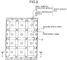
- FIG. 2 depicts an arrangement of the spray nozzles 22A in a simplified manner.
- FIG. 3 schematically depicts an atomized state of the CO 2 absorbent 14 sprayed from the spray nozzles 22A.
- the CO 2 absorber 15 has a square cross-sectional shape with respect to a flow direction of the flue gas 11. Accordingly, the number of liquid feed pipes can be increased by enlarging the cross-section in one direction without changing the arrangement cf the nozzles, thereby enabling to increase tne amount of processing gas and to easily realize scale-up of the CO 2 absorber 15.
- the spray nozzle 22A includes a liquid dispersion nozzle 25 and a wall-surface dedicated nozzle 26.
- the liquid dispersion nozzle 25 is provided inside of the wall-surface dedicated nozzle 26 in the CO 2 absorber 15.
- the wall-surface dedicated nozzle 26 is provided along the vicinity of a wall surface 27 in the CO 2 absorber 15.
- the vicinity of the wall surface 27 refers to a state where the wall-surface dedicated nozzle 26 does not come into contact with the wall surface 27 and there is a predetermined gap between the wall-surface dedicated nozzle 26 and the wall surface 27.
- the liquid dispersion nozzle 25 sprays the CO 2 absorbent 14 substantially uniformly in a square shape in the CO 2 absorber 15 (a first spray area A in FIGS. 2 and 3 ).
- the first spray area A of the CO 2 absorbent 14 sprayed from the liquid dispersion nozzle 25 overlaps on a part of the first spray area A of the CO 2 absorbent 14 sprayed from other adjacent liquid dispersion nozzles 25.
- the quantity of water of the CO 2 absorbent 14 sprayed from the liquid dispersion nozzle 25 decreases as moving away from the liquid dispersion nozzle 25. However, in an area in which the quantity of water of the CO 2 absorbent 14 sprayed from the liquid dispersion nozzle 25 decreases, because the CO 2 absorbent 14 overlaps with the CO 2 absorbent 14 sprayed from the other adjacent liquid dispersion nozzle 25, the quantity of water of the CO 2 absorbent 14 in the CO 2 absorber 15 can be maintained substantially uniform.
- the shape of the first spray area A of the CO 2 absorbent 14 sprayed from the liquid dispersion nozzle 25 is not limited to a square shape, and other shapes such as a circle and an elliptical shape can be also used.
- the wall-surface dedicated nozzle 26 sprays the CO 2 absorbent 14 toward inside of the CO 2 absorber 15.
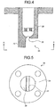
- FIG. 4 depicts a cross-sectional shape of the wall-surface dedicated nozzle 26 in a simplified manner
- FIG. 5 is a view from a direction of A-A in FIG. 4 .
- the wall-surface dedicated nozzle 26 includes a nozzle body 28 and a shield plate 29.
- the shield plate 29 is provided integral with the nozzle body 28 in an extended condition on a side of the wall surface 27 of the CO 2 absorber 15.
- the CO 2 absorbent 14 sprayed from a nozzle hole 30 of the wall-surface dedicated nozzle 26 hits the shield plate 29, and is sprayed to the inside of the CO 2 absorber 15 while suppressing that the CO 2 absorbent 14 is sprayed on the side of the wall surface 27 of the CO 2 absorber 15 (a second spray area B in FIGS. 2 and 3 ).
- the CO 2 absorbent 14 can be sprayed substantially uniformly into the CO 2 absorber 15, and by providing the wall-surface dedicated nozzles 26 along the wall surface 27 of the CO 2 absorber 15, it is suppressed that the CO 2 absorbent 14 comes into contact with the wall surface 27 of the CO 2 absorber 15. Accordingly, the CO 2 absorbent 14 sprayed into the CO 2 absorber 15 can be dispersed up to the vicinity of the wall surface 27 of the CO 2 absorber 15, with the quantity of water thereof being maintained substantially uniform.
- FIG. 6 schematically depicts water quantity distribution of the CO 2 absorbent 14 in the direction of A-A in FIG. 2 at a cross-section of the CO 2 absorber 15.
- the density of water in the CO 2 absorber 15, because density of water is in a range equal to or more than 90% to equal to or less than 110%, the density of water can be maintained in a distribution range of 100% ( ⁇ 10%), and the density of water can be maintained about 90% even on the wall surface 27 of the CO 2 absorber 15.
- the quantity of water of the CO 2 absorbent 14 to be fed into the CO 2 absorber 15 can be made substantially uniform up to the vicinity of the wall surface 27 of the CO 2 absorber 15.
- the flue gas 11 passes through the CO 2 absorber 15 without coming into contact with the CO 2 absorbent 14. Furthermore, because the amount of the CO 2 absorber 15 sprayed onto the wall surface 27 of the CO 2 absorber 15 decreases, the amount of the CO 2 absorbent 14 stored at the bottom of the CO 2 absorber 15 without absorbing CO 2 in the flue gas 11 can be decreased.
- the CO 2 absorbent 14 can be dispersed substantially uniformly in the CO 2 absorber 15, and by providing the wall-surface dedicated nozzles 26 along the wall surface 27 of the CO 2 absorber 15, it can be suppressed that the CO 2 absorbent 14 comes into contact with the wall surface 27 of the CO 2 absorber 15. Therefore, the CO 2 absorbent 14 sprayed into the CO 2 absorber 15 can be dispersed, with the quantity of water thereof being made substantially uniform up to the vicinity of the wall surface 27 of the CO 2 absorber 15, regardless of the size of the CO 2 recovery unit 10 or the like.
- the material cost and manufacturing cost of the distributor, and the installation cost thereof in the CO 2 absorber 15 are reduced as compared with a case where the trough-type liquid distributor or the like is used, thereby enabling to decrease the facility cost of the gas-liquid contactor.
- Gaps between the respective nozzle holes of the liquid dispersion nozzle 25 and the wall-surface dedicated nozzle 26 are relatively different depending on the size of the respective nozzle holes and a flow rate and a spray area of the CO 2 absorbent 14 sprayed from the respective nozzle holes.
- the gape between the respective nozzle holes of the liquid dispersion nozzle 25 and the wall-surface dedicated nozzle 26 can be set so that interference between the CO 2 absorbent 14 sprayed from the liquid dispersion nozzles 25 and the CO 2 absorbent 14 sprayed from the wall-surface dedicated nozzles 26 does not occur, for example, at the time of spraying, and the amount of the CO 2 absorbent 14 sprayed into the CO 2 absorber 15 becomes uniform.
- the spray nozzle 22A including the liquid dispersion nozzle 25 and the wall-surface dedicated nozzle 26 is used.
- a corner-part dedicated nozzle 31 can be provided at the corner part of tne wall surface 27 of the CO 2 absorber 15.
- FIG. 8 depicts a cross-sectional shape of the corner-part dedicated nozzle 31 in a simplified manner.
- FIG. 9 is a view from a direction of A-A in FIG. 8 .
- the corner-part dedicated nozzle 31 includes a nozzle body 32, and an L-shaped shield plate 33 having an L-shaped cross-sectional shape in the longitudinal direction of the nozzle body 32.
- the L-shaped shield plate 33 is provided integral with the nozzle body 32 in an extended condition on the side of the wall surface 27 of the CO 2 absorber 15. Therefore, the CO 2 absorbent 14 sprayed from a nozzle hole 34 of the corner-part dedicated nozzle 31 hits botn surfaces of the L-shaped shield plate 33, and is sprayed to the inside of the CO 2 absorber 15 while suppressing that the CO 2 absorbent 14 is sprayed to the corner side of the wall surface 27 of the CO 2 absorber 15 (a third spray area C in FIG. 7 ).
- the corner-part dedicated nozzle 31 sprays the CO 2 absorbent 14 to the inside of the CO 2 absorber 15, it can be suppressed that the CO 2 absorbent 14 sprayed from the corner-part dedicated nozzle 31 is dispersed to the corner part in a cross-section of the CO 2 absorber 15. Therefore, the CO 2 absorbent 14 can be dispersed uniformly up to the vicinity of the wall surface 27, and the amount of the CO 2 absorber 15 coming into contact with the wall surface 27 of the CO 2 absorber 15 can be decreased further. Accordingly, the amount of the CO 2 absorbent 14 stored at the bottcm of the CO 2 absorber 15 without absorbing CO 2 in the flue gas 11 can be further decreased.
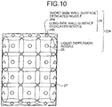
- FIGS. 10 and 11 are other configuration diagrams of the arrangement cf the spray nozzles 22A.
- nozzles of different types can be provided as a short-side wall-surface dedicated nozzle 26a provided near the wall surface 27 on the short side of the CO 2 absorber 15 and a long-side wall-surface dedicated nozzle 26b provided near the wall surface 27 on the long side of the CO 2 absorber 15. Accordingly, the CO 2 absorbent 14 can be sprayed at an arbitrary ratio onto the short side and the long side of the CO 2 absorber 15.
- a result of a CO 2 recovery rate when the gas-liquid contactor 21A according to the present embodiment is applied to the CO 2 absorber 15 is shown in Table 1.
- Table 1 when a CO 2 absorption rate at the time of decreasing the amount to be sprayed onto the wall surface without arranging the wall-surface dedicated nozzle 26 is designated as a reference value (1.0), the CO 2 absorption rate becomes about 1.1 by arranging the wall-surface dedicated nozzle 26.
- the cross-sectional shape of the CC absorber 15 with respect to the flow direction of the flue gas 11 is square.
- the cross-sectional shape of the CO 2 absorber 15 is not limited thereto, and it can be circular or elliptical.
- An atomizing pressure of the respective nozzles is set to equal to cr lower than 0.2 megapascal, preferably equal to cr lower than 0.15 megapascal, and more preferably equal to or lower than 0.1 megapascal. 3y decreasing the nozzle atomizing pressure, the pump power consumption can be decreased, and a mist scattering amount can be suppressed.
- the CO 2 absorber 15 includes a water washing unit 42 and a demister 43 in an upper part of the CO 2 recovering unit 24.
- CO 2 -removed flue gas 41 of which CO 2 has been removed is emitted to outside of the system from a column top part, after the CO 2 absorbent 14 entrained by the CO 2 -removed flue gas 41 is removed by the water washing unit 42 and the demister 43.
- the rich solution 16 having absorbed CO 2 in the flue gas 11 in the CO 2 recovering unit 24 is stored at the bottom of the CO 2 absorber 15.
- the rich solution 16 stored at the bottom of the CO 2 absorber 15 is pressure-fed from a column bottom part of the CO 2 absorber 15 by a rich solvent pump 44 provided outside, heat-exchanged with the CO 2 absorbent 14 regenerated in the regenerator 17 in a rich-lean solution heat exchanger 45, and fed into the column from the column top part of the regenerator 17.
- the regenerator 17 regenerates the CO 2 absorbent 14 as the lean solution 14 by emitting CO 2 from the rich solution 16. Most part of CO 2 in the rich solution 16 emitted into the column of the regenerator 17 from the column top part of the regenerator 17 is emitted due to the endoergic reaction, and the rich solution 16 becomes the CO 2 absorbent (the lean solution) 14 in which almost all CO 2 is removed, when reaching the column bottom part of the regenerator 17.
- the lean solution 14 stored at the bottom of the regenerator 17 as fed as a CO 2 absorbent by a lean solvent pump 46, cooled by neat exchange with cooling water 48 in a lean solvent cooler 47, and fed to the CO 2 absorber 15.
- CO 2 gas 51 accompanied by water vapor is emitted from the column top part of the regenerator 17.
- the CO 2 gas 51 accompanied by water vapor is derived from the column top part of the regenerator 17, water vapor contained in the CO 2 gas 51 is condensed by cooling water 53 in a capacitor 52.
- water 56 is separated in a separation drum 54, CO 2 gas 55 is emitted to outside of the system and recovered.
- the water 56 separated in the separation drum 54 is fed tc the upper part of the regenerator 17 by a condensed-water circulation pump 57.
- the wall-surface dedicated nozzles 26 are provided along the vicinity of the wall surface 27 in the CO 2 absorber 15, and the liquid dispersion nozzles 25 are provided inside of the wall-surface dedicated nozzles 26.
- the CO 2 absorbent 14 is sprayed into the CO 2 absorber 15 from the liquid dispersion nozzles 25 and the wall-surface dedicated nozzles 26, the amount of the CO 2 absorbent 14 sprayed onto the wall surface 27 in the column is decreased.
- the CO 2 absorbent 14 is dispersed substantially uniformly up to the vicinity of the wall surface 27 in the CO 2 absorber 15, and the flue gas 11 fed into the column can be efficiently brought into contact with the CO 2 absorbent 14. Accordingly, the absorption performance of the CO 2 absorbent 14 for absorbing CO 2 can be improved, it can be suppressed that the flue gas 11 passes through the CO 2 absorber 15 without coming into contact with the CO 2 absorbent 14, and the facility cost can be reduced. Further, because the amount of the CO 2 absorbent 14 sprayed onto the wall surface 27 of the CO 2 absorber 15 can be reduced, the absorbed amount of CO 2 per amount of the CO 2 absorbent 14 fed to the CO 2 absorber 15 can be increased.
- the CO 2 absorbent 14 which does not absorb CO 2 in the flue gas 11 and is stored at the bottom of the CO 2 absorber 15, is fed to the regenerator 17, the CO 2 absorbent 14 can be used efficiently without wastefully consuming amine contained in the CO 2 absorbent 14, and steam required for emitting CO 2 contained in the CO 2 absorbent 14 in the regenerator 17 can oe efficiently used without any waste. Consequently, the operation efficiency of the CO 2 recovery unit 10 can be increased.
- CO 2 in the flue gas 11 can be absorbed by the CO 2 absorbent 14 efficiently and stably, without being affected by the size of the CO 2 recovery unit 10 or the like.
- gas-liquid contactor according to the present embodiment is used for the CO 2 absorber 15 in the CO 2 recovery unit 10 is explained above.
- the present embodiment is not limited thereto, and for example, the gas-liquid contactor can be used in the cooling column 13 or the like.
- gas-liquid contactor is not limited to the case applied to the CO 2 recovery unit 10, and is applicable to any device having a spray nozzle to be used for spraying liquid downward to bring gas and liquid into contact with each other, such as a flue gas desulfurizer.
- a CO 2 recovery unit according to a second embodiment of the present invention in which a gas-liquid contactor is applied to a CO 2 absorber is explained below with reference to the drawings.
- the gas-liquid contactor according to the second embodiment is used as a CO 2 absorber as in the configuration of the CO 2 recovery unit shown in FIG. 1 .
- the configuration of the CO 2 recovery unit according to the present embodiment including the gas-liquid contactor is identical to that of the CO 2 recovery unit shown in FIG. 1 , a drawing of the configuration of the CO 2 recovery unit is omitted, and only a drawing of the configuration of the CO 2 absorber is used to explain the present embodiment.
- Constituent elements identical to those of the CO 2 recovery unit shown in FIG. 1 are denoted by like reference signs and explanations thereof will be omitted.
- FIG. 12 depicts a configuration of the gas-liquid contactor according to the second embodiment of the present invention in a simplified manner.
- a spray nozzle 22B of a gas-liquid contactor 21B according to the present embodiment includes two types of liquid dispersion nozzles 25 and wall-surface dedicated nozzles 26 that can be used according to the load operation of the CO 2 recovery unit 10.
- the two types of nozzles are alternately provided in a direction orthogonal to a gas flow direction of the flue gas 11 in the CO 2 absorber 15. That is, the liquid dispersion nozzle 25 includes a high-load liquid-dispersion nozzle 25A and a low-load liquid-dispersion nozzle 25B.
- the wall-surface dedicated nozzle 26 includes a high-load wall-surface dedicated nozzle 26A and a low-load wall-surface dedicated nozzle 26B.
- the high-load liquid-dispersion nozzles 25A and the low-lead liquid-dispersion nozzles 25B are alternately provided in the direction orthogonal to the gas flow direction of the flue gas 11 in the CO 2 absorber 15.
- the high-load wall-surface dedicated nozzles 26A and the low-load wall-surface dedicated nozzles 26B are alternately provided on the wall surface 27 of the CO 2 absorber 15 in the direction orthogonal to the gas flow direction of the flue gas 11.
- An absorbent feed pipe 22a feeds the CO 2 absorbent 14 to the high-load liquid-dispersion nozzles 25A and the low-load liquid-dispersion nozzles 25B, and an absorbent feed pipe 23b feeds the CO 2 absorbent 14 to the high-load wall-surface dedicated nozzles 26A and the low-load wall-surface dedicated nozzles 26B.
- the CO 2 absorbent 14 can be sprayed from the same height in the column of the CO 2 absorber 15 by providing tne high-load liquid-dispersion nozzles 25A and the high-load wall-surface dedicated nozzles 26A and the low-load liquid-dispersion nozzles 25B and the low-load wall-surface dedicated nozzles 26B in the CO 2 absorber 15.
- the gas-liquid contactor 21B uses the high-load liquid-dispersion nozzles 25A or the low-load liquid-dispersion nozzles 25B and uses the high-load wall-surface dedicated nozzles 26A cr the low-load wall-surface dedicated nozzles 26B according to the load operation of the CO 2 recovery unit 10. Accordingly, the CO 2 absorbent 14 can be fed in an appropriate quantity of water into the CO 2 absorber 15 according to the load operation of the CO 2 recovery unit 10.
- the load operation of the CO 2 recovery unit 10 can be determined based on a flow rate of the flue gas 11 fed into the CO 2 absorber 15.
- the CO 2 absorbent 14 is sprayed from the high-load liquid-dispersion nozzles 25A and the high-load wall-surface dedicated nozzles 26A.
- the CO 2 absorbent 14 is sprayed from the low-load liquid-dispersion nozzles 25B and the low-load wall-surface dedicated nozzles 26B.
- FIG. 13 is an example of a relation between a flow rate and an atomizing pressure of a nozzle to be used. In FIG.
- the predetermined threshold is 55%.
- the low-load liquid-dispersion nozzles 25B and the low-load wall-surface dedicated nozzles 26B are used to spray the CO 2 absorbent 14 into the CO 2 absorber 15.
- the high-load liquid-dispersion nozzles 25A and the high-load wall-surface dedicated nozzles 26A are used to spray the CO 2 absorbent 14 into the CO 2 absorber 15.
- the atomizing pressure can be decreased under all load conditions and liquid can be dispersed uniformly. Accordingly, the amount of mist of the CO 2 absorbent 14 in the air caused by countercurrent contact between the flue gas 11 and the CO 2 absorbent 14 can be decreased.
- the pump power of the lean solvent pump 46 and the like required for feeding the CO 2 absorbent 14 into the CO 2 absorber 15 can be decreased.
- the predetermined threshold of the flow rate of the flue gas 11 for changing the use of the high-load liquid-dispersion nozzles 25A or the low-load liquid-dispersion nozzles 25B and the high-load wall-surface dedicated nozzles 26A or the low-load wall-surface dedicated nozzles 26B is set to 55% of the flow rate of the flue gas 11 as a reference.
- tne threshold of the flow rate of the flue gas 11 is 55% is explained above with reference to FIG. 13 .
- the present embodiment is not limited thereto, and the flow rate can be appropriately changed according to the size of the CO 2 recovery unit 10 or the CO 2 absorber 15, and an operating condition.
- the CO 2 absorbent 14 can be fed into the CO 2 absorber 15 corresponding to the load operation of the CO 2 recovery unit 10, thereby enabling to absorb CO 2 in the flue gas 11 by the CO 2 absorbent 14 more efficiently and stably.
- the load operation of the CO 2 recovery unit 10 is determined based on the flow rate of the flue gas 11 fed into the CO 2 absorber 15.
- the present embodiment is not limited thereto, and the load operation of the CO 2 recovery unit 10 can be determined based on the CO 2 recovery amount, the consumption power of an air blower, or an aperture of a damper.
- the high-load liquid-dispersion nozzles 25A and the low-load liquid-dispersion nozzles 25B are alternately provided in the direction orthogonal to the gas flow direction of the flue gas 11 in the CO 2 absorber 15.
- the present embodiment is not limited thereto, and after a plurality of high-load liquid-dispersion nozzles 25A are continuously provided in the direction orthogonal to the gas flow direction of the flue gas 11 in the CO 2 absorber 15, and then the low-load liquid-dispersion nozzles 25B can be provided.
- the high-load liquid-dispersion nozzles 25A and the high-load wall-surface dedicated nozzles 26A are used.
- the present embodiment is not limited thereto, and the low-load liquid-dispersion nozzles 25B and the low-lead wall-surface dedicated nozzles 26B can be used, or the high-load liquid-dispersion nozzles 25A and the high-lead wall-surface dedicated nozzles 26A, and the low-load liquid-dispersion nozzles 25B and the low-load wall-surface dedicated nozzles 26B can be used.
- the spray nozzle 22B is not limited thereto, and more than three types of the spray nozzles 22B including a medium-load nozzle in addition to the high-load nozzle and the low-load nozzle can be used.
- a CO 2 recovery unit according to a third embodiment of the present invention in which a gas-liquid contactor is applied to a CO 2 absorber is explained with reference to the drawings.
- the gas-liquid contactor according to the present embodiment is used as a CO 2 absorber of the CO 2 recovery unit shown in FIG. 1 , as in the gas-liquid contactor according to the second embodiment.
- the configuration of the CO 2 recovery unit according to the present embodiment in which the gas-liquid contactor is applied to the CO 2 absorber is identical to that of the CO 2 recovery unit shown in FIG. 1 , a drawing of the configuration of the CO 2 recovery unit is omitted, and only a drawing of a part of the configuration of the CC 2 absorber is used to explain the present embodiment.
- Constituent elements identical to these of the CO 2 recovery unit shown in FIG. 1 are denoted by like reference signs and explanations thereof will be omitted.
- FIG. 14 depicts a configuration of the gas-liquid contactor according to the third embodiment of the present invention in a simplified manner.
- the high-load liquid-dispersion nozzles 25A and the low-load liquid-dispersion nozzles 25B are alternately provided in the gas flow direction cf the flue gas 11 in the CO 2 absorber 15, and the high-load wall-surface dedicated nozzles 26A and the low-load wall-surface dedicated nozzles 26E are alternately provided in the gas flew direction of the flue gas 11 near the wall surface 27 of the CO 2 absorber 15.
- the high-load liquid-dispersion nozzles 25A and the low-load liquid-dispersion nozzles 25B are alternately provided in the direction orthogonal to the gas flow direction of the flue gas 11 in the CO 2 absorber 15, with arrangement positions of the respective nozzles being changed.
- the high-load wall-surface dedicated nozzles 26A and the low-load wall-surface dedicated nozzles 26B are alternately provided in the direction orthogonal to the gas flow direction of the flue gas 11 in the CO 2 absorber 15, with arrangement positions of the respective nozzles being changed.
- the high-load liquid-dispersion nozzles 25A and the low-load liquid-dispersion nozzles 25B are alternately provided in the gas flow direction of the flue gas 11 in the CO 2 absorber 15 and arrangement positions in the direction orthogonal to the gas flow direction of the flue gas 11 are changed, and the high-load wall-surface dedicated nozzles 26A and the low-load wall-surface dedicated nozzles 26B are alternately provided in the gas flow direction of the flue gas 11 in the CO 2 absorber 15 and arrangement positions in the direction orthogonal tc the gas flow direction of the flue gas 11 are changed. Accordingly, the pressure less of the flue gas 11 at the tine of passing through the gas-liquid contactor according to the present embodiment can be decreased. Therefore, the power of the air blower required for feeding the flue gas 11 into the CO 2 absorber 15 can be decreased.
- the high-load liquid-dispersion nozzles 25A and the low-load liquid-dispersion nozzles 258 are provided alternately in the gas flow direction of the flue gas 11 in the CO 2 absorber 15, and the high-load wall-surface dedicated nozzles 26A and the low-load wall-surface dedicated nozzles 26B are provided alternately in the gas flow direction of the flue gas 11 on the wall surface 27 of the CO 2 absorber 15.
- the present embedment is not limited thereto.
- the low-load liquid-dispersion nozzles 25B or the low-load wall-surface dedicated nozzles 26B can be provided.
- the pressure loss of the flue gas 11 to be fed to the CO 2 absorber 15 can be decreased, thereby enabling to absorb CO 2 in the flue gas 11 into the CO 2 absorbent 14 more efficiently and stably corresponding to the load operation of the CO 2 recovery unit 10, while decreasing the power required for feeding the flue gas 11 into the CO 2 absorber 15.
Landscapes
- Chemical & Material Sciences (AREA)
- Chemical Kinetics & Catalysis (AREA)
- Organic Chemistry (AREA)
- Engineering & Computer Science (AREA)
- Analytical Chemistry (AREA)
- General Chemical & Material Sciences (AREA)
- Oil, Petroleum & Natural Gas (AREA)
- Inorganic Chemistry (AREA)
- Gas Separation By Absorption (AREA)
- Treating Waste Gases (AREA)
- Carbon And Carbon Compounds (AREA)
Claims (8)
- Gas-Flüssigkeits-Schütz (21A, 21B, 21C) zum Sprühen einer Flüssigkeit nach unten in eine Kontaktsäule, in der Gas aufsteigt und strömt, um das aufsteigende Gas und die Flüssigkeit miteinander in Kontakt zu bringen,
das Gas-Flüssigkeits-Schütz (21A, 21B, 21C) umfassend:eine für eine Wandfläche bestimmte Düse (26), die entlang einer Wandfläche (27) in der Kontaktsäule bereitgestellt ist, zum Sprühen der Flüssigkeit in Richtung der Innenseite der Kontaktsäule, undeine Flüssigkeitsdispergierdüse (25), die in der Kontaktsäule weiter innen als die für die Wandfläche bestimmte Düse (26) angeordnet ist, zum gleichmäßigen Sprühen der Flüssigkeit in die Kontaktsäule, dadurch gekennzeichnet, dassdie für die Wandfläche bestimmte Düse (26) einen Düsenkörper (28) und eine Abschirmplatte (29) beinhaltet, die mit dem Düsenkörper (28) in einem erweiterten Zustand an einer Seite der Wandfläche (27) einstückig bereitgestellt ist, sodass die Flüssigkeit, die aus einer Düsenöffnung (30) der für die Wand bestimmten Düse (26) gesprüht wird, auf die Abschirmplatte (29) trifft und auf die Innenseite der Kontaktsäule gesprüht wird, während verhindert wird, dass die Flüssigkeit auf die Seite der Wandfläche (27) der Kontaktsäule gesprüht wird. - Gas-Flüssigkeits-Schütz (21A, 21B, 21C) nach Anspruch 1, wobei eine Querschnittsform der Kontaktsäule in einer Richtung, die senkrecht zu der Strömungsrichtung des Gases ist, quadratisch ist.
- Gas-Flüssigkeits-Schütz (21A, 21B, 21C) nach Anspruch 2, ferner umfassend eine für einen Eckteil bestimmte Düse (31), die an dem Eckteil im Abschnitt der Kontaktsäule bereitgestellt ist, zum Sprühen der Flüssigkeit in Richtung der Innenseite der Kontaktsäule.
- Gas-Flüssigkeits-Schütz (21A, 21B, 21C) nach einem der Ansprüche 1 bis 3, wobei die Flüssigkeitsdispergierdüse (25) und die für die Wandfläche bestimmte Düse (26) zwei oder mehr Arten von Düsen beinhalten, und wobei das Gas-Flüssigkeits-Schütz derart ausgelegt ist, dass die zwei oder mehr Arten von Düsen gemäß einer Strömungsrate des Gases verwendet werden.
- Gas-Flüssigkeits-Schütz (21A, 21B, 21C) nach Anspruch 4, wobei
die Flüssigkeitsdispergierdüse (25) eine Hochlast-Flüssigkeitsdispergierdüse (25A) und eine Schwachlast-Flüssigkeitsdispergierdüse (25B) beinhaltet, und
die für die Wandfläche bestimmte Düse (26) eine für die Wandfläche bestimmte Hochlast-Düse (26A) und eine für die Wandfläche bestimmte Schwachlast-Düse (26B) beinhaltet, und wobei
wenn die Strömungsrate des Gases gleich oder höher als ein vorbestimmter Schwellenwert ist, die Flüssigkeit aus der Hochlast-Flüssigkeitsdispergierdüse (25A) und aus der für die Wandfläche bestimmten Hochlast-Düse (26A) gesprüht wird, und
wenn die Strömungsrate des Gases niedriger als ein vorbestimmter Schwellenwert ist, die Flüssigkeit aus der Schwachlast-Flüssigkeitsdispergierdüse (25B) und aus der für die Wandfläche bestimmten Hochlast-Düse (26B) gesprüht wird. - Gas-Flüssigkeits-Schütz (21A, 21B, 21C) nach Anspruch 4 oder 5, wobei Flüssigkeitsdispergierdüsen (25) und für Wandflächen bestimmte Düsen (26) verschiedener Arten in der zu der Strömungsrichtung des Gases in der Kontaktsäule senkrechten Richtung abwechselnd bereitgestellt sind.
- Gas-Flüssigkeits-Schütz (21A, 21B, 21C) nach Anspruch 6, wobei
die Flüssigkeitsdispergierdüsen (25) und die für die Wandfläche bestimmten Düsen (26) verschiedener Arten abwechselnd in der Strömungsrichtung des Gases in der Kontaktsäule bereitgestellt sind, und
die Flüssigkeitsdispergierdüsen (25) und die für die Wandfläche bestimmten Düsen (26) verschiedener Arten in der zu der Strömungsrichtung des Gases in der Kontaktsäule senkrechten Richtung abwechselnd bereitgestellt sind, wobei die Anordnungspositionen der jeweiligen Düsen verändert sind. - CO2-Rückgewinnungseinheit (10), umfassend:einen CO2-Absorber (15), der die Kontaktsäule des Gas-Flüssigkeits-Schützes (21A, 21B, 21C) nach einem der Ansprüche 1 bis 7 beinhaltet, wobei der CO2-Absorber dafür ausgelegt ist, Rauchgas, das CO2 enthält, in Kontakt mit einem CO2-Absorptionsmittel zu bringen, das CO2 absorbiert, um CO2 aus dem Rauchgas zu entfernen, undeinen Regenerator (17) zum Abgeben von CO2 aus dem CO2-Absorptionsmittel, das CO2 absorbiert hat, um das CO2-Absorptionsmittel zu regenerieren.
Applications Claiming Priority (2)
| Application Number | Priority Date | Filing Date | Title |
|---|---|---|---|
| JP2010171064A JP5693076B2 (ja) | 2010-07-29 | 2010-07-29 | 気液接触装置及びco2回収装置 |
| PCT/JP2011/060082 WO2012014544A1 (ja) | 2010-07-29 | 2011-04-25 | 気液接触装置及びco2回収装置 |
Publications (4)
| Publication Number | Publication Date |
|---|---|
| EP2609986A1 EP2609986A1 (de) | 2013-07-03 |
| EP2609986A4 EP2609986A4 (de) | 2014-04-09 |
| EP2609986B1 true EP2609986B1 (de) | 2018-08-29 |
| EP2609986B8 EP2609986B8 (de) | 2018-11-21 |
Family
ID=45529767
Family Applications (1)
| Application Number | Title | Priority Date | Filing Date |
|---|---|---|---|
| EP11812139.1A Active EP2609986B8 (de) | 2010-07-29 | 2011-04-25 | Gas-flüssigkeit-kontaktor und vorrichtung zur co2-gewinnung |
Country Status (7)
| Country | Link |
|---|---|
| US (1) | US9227154B2 (de) |
| EP (1) | EP2609986B8 (de) |
| JP (1) | JP5693076B2 (de) |
| AU (1) | AU2011284040B2 (de) |
| CA (2) | CA2804276C (de) |
| RU (1) | RU2532175C2 (de) |
| WO (1) | WO2012014544A1 (de) |
Families Citing this family (7)
| Publication number | Priority date | Publication date | Assignee | Title |
|---|---|---|---|---|
| US9492786B2 (en) * | 2011-11-22 | 2016-11-15 | Fluor Corporation | Multi-purpose absorber |
| US9623366B2 (en) | 2013-03-04 | 2017-04-18 | Mitsubishi Heavy Industries, Ltd. | CO2 recovery system and CO2 recovery method |
| US10338012B2 (en) | 2016-03-09 | 2019-07-02 | Toshiba Medical Systems Corporation | Photon counting detector and X-ray computed tomography (CT) apparatus |
| JP7524086B2 (ja) * | 2021-01-15 | 2024-07-29 | 株式会社東芝 | 二酸化炭素回収システムおよび二酸化炭素回収システムの運転方法 |
| JP7523078B2 (ja) * | 2022-11-21 | 2024-07-26 | 株式会社大気社 | 放出処理装置、及び二酸化炭素回収システム |
| JP7510479B2 (ja) * | 2022-11-21 | 2024-07-03 | 株式会社大気社 | 回収システム |
| EP4403249A1 (de) * | 2023-01-23 | 2024-07-24 | Technip Energies France | Industrieanlage zur gasbehandlung |
Family Cites Families (14)
| Publication number | Priority date | Publication date | Assignee | Title |
|---|---|---|---|---|
| JPS5060477A (de) * | 1973-09-28 | 1975-05-24 | ||
| JPS56136617A (en) * | 1980-03-25 | 1981-10-26 | Babcock Hitachi Kk | Gas absorption tower |
| JP2506351B2 (ja) * | 1986-12-16 | 1996-06-12 | バブコツク日立株式会社 | 脱硫装置 |
| JPH0773658B2 (ja) * | 1988-04-07 | 1995-08-09 | 三菱重工業株式会社 | 排ガスの脱硫方法 |
| DE19736761C2 (de) * | 1997-08-23 | 2002-06-27 | Lechler Gmbh & Co Kg | Reinigungseinrichtung zur Abscheidung gas- oder partikelförmiger Inhaltsstoffe aus Gasströmen |
| DE19755571A1 (de) * | 1997-12-15 | 1999-06-17 | Abb Research Ltd | Absorberturm |
| JP2001009237A (ja) * | 1999-07-02 | 2001-01-16 | Ishikawajima Harima Heavy Ind Co Ltd | スプレー式排煙脱硫装置 |
| RU2217221C2 (ru) * | 2001-06-27 | 2003-11-27 | Курский государственный технический университет | Способ и устройство для выделения двуокиси углерода из дымовых газов |
| WO2005072851A1 (ja) * | 2004-01-30 | 2005-08-11 | Kabushiki Kaisha Toshiba | 排ガス中の二酸化炭素の回収システムおよび回収方法 |
| JP5289668B2 (ja) * | 2005-05-18 | 2013-09-11 | バブコック日立株式会社 | 湿式排煙脱硫装置 |
| US7976622B2 (en) * | 2006-01-12 | 2011-07-12 | Babcock-Hitachi Kabushiki Kaisha | Wet flue gas desulfurization apparatus |
| JP5230088B2 (ja) * | 2006-09-06 | 2013-07-10 | 三菱重工業株式会社 | Co2回収装置及び方法 |
| JP5527742B2 (ja) * | 2007-09-04 | 2014-06-25 | シエル・インターナシヨネイル・リサーチ・マーチヤツピイ・ベー・ウイ | 噴射ノズルマニホールド及びその使用により高温ガスを急冷する方法 |
| JP4225517B1 (ja) * | 2008-09-30 | 2009-02-18 | 隆二 塩▲崎▼ | 二酸化炭素濃度低減装置 |
-
2010
- 2010-07-29 JP JP2010171064A patent/JP5693076B2/ja active Active
-
2011
- 2011-04-25 CA CA2804276A patent/CA2804276C/en active Active
- 2011-04-25 CA CA2883462A patent/CA2883462C/en active Active
- 2011-04-25 WO PCT/JP2011/060082 patent/WO2012014544A1/ja not_active Ceased
- 2011-04-25 EP EP11812139.1A patent/EP2609986B8/de active Active
- 2011-04-25 US US13/807,510 patent/US9227154B2/en active Active
- 2011-04-25 AU AU2011284040A patent/AU2011284040B2/en active Active
- 2011-04-25 RU RU2012157575/05A patent/RU2532175C2/ru active
Non-Patent Citations (1)
| Title |
|---|
| None * |
Also Published As
| Publication number | Publication date |
|---|---|
| US20130098248A1 (en) | 2013-04-25 |
| JP2012030168A (ja) | 2012-02-16 |
| AU2011284040B2 (en) | 2014-10-16 |
| EP2609986B8 (de) | 2018-11-21 |
| RU2532175C2 (ru) | 2014-10-27 |
| RU2012157575A (ru) | 2014-07-10 |
| US9227154B2 (en) | 2016-01-05 |
| EP2609986A1 (de) | 2013-07-03 |
| CA2804276A1 (en) | 2012-02-02 |
| EP2609986A4 (de) | 2014-04-09 |
| CA2804276C (en) | 2015-12-01 |
| CA2883462A1 (en) | 2012-02-02 |
| CA2883462C (en) | 2015-12-01 |
| JP5693076B2 (ja) | 2015-04-01 |
| WO2012014544A1 (ja) | 2012-02-02 |
| AU2011284040A1 (en) | 2013-01-24 |
Similar Documents
| Publication | Publication Date | Title |
|---|---|---|
| US9227154B2 (en) | Gas-liquid contactor and CO2 recovery unit | |
| US8080089B1 (en) | Method and apparatus for efficient gas treating system | |
| CA2770828C (en) | Co2 recovery system and recovery method for moisture containing co2 gas | |
| JP5881617B2 (ja) | 二酸化炭素捕捉プロセス用の水洗法及びシステム | |
| EP2883595A1 (de) | Abgasbehandlungssystem | |
| CA3008221C (en) | Co2 recovery device and co2 recovery method | |
| US20160310894A1 (en) | Gas-liquid contactor and co2 recovery device | |
| US10065149B2 (en) | Gas-liquid contactor and CO2-recovering apparatus provided therewith | |
| US9399189B2 (en) | CO2 recovery device | |
| JPH119956A (ja) | 湿式排煙脱硫装置の吸収塔 | |
| JP7524086B2 (ja) | 二酸化炭素回収システムおよび二酸化炭素回収システムの運転方法 | |
| JP7479788B2 (ja) | 二酸化炭素回収システムおよびその運転方法 | |
| KR101725555B1 (ko) | 흡수효율이 향상된 이산화탄소 회수장치 및 회수방법 | |
| JP2015502847A (ja) | 二酸化炭素の吸収のための方法及び装置 | |
| KR102960558B1 (ko) | 이산화탄소 포집용 흡수탑 | |
| CN217340752U (zh) | 一种燃煤锅炉烟气处理系统 | |
| CA3179020C (en) | Co2 recovery unit and co2 recovery method | |
| KR102960557B1 (ko) | 이산화탄소 포집용 흡수탑 | |
| CN203090742U (zh) | 一种设有气液再分布装置的脱硫吸收塔 |
Legal Events
| Date | Code | Title | Description |
|---|---|---|---|
| PUAI | Public reference made under article 153(3) epc to a published international application that has entered the european phase |
Free format text: ORIGINAL CODE: 0009012 |
|
| 17P | Request for examination filed |
Effective date: 20121228 |
|
| AK | Designated contracting states |
Kind code of ref document: A1 Designated state(s): AL AT BE BG CH CY CZ DE DK EE ES FI FR GB GR HR HU IE IS IT LI LT LU LV MC MK MT NL NO PL PT RO RS SE SI SK SM TR |
|
| DAX | Request for extension of the european patent (deleted) | ||
| A4 | Supplementary search report drawn up and despatched |
Effective date: 20140307 |
|
| RIC1 | Information provided on ipc code assigned before grant |
Ipc: B01D 53/14 20060101ALI20140304BHEP Ipc: B01D 53/18 20060101ALI20140304BHEP Ipc: C01B 31/20 20060101ALI20140304BHEP Ipc: B01D 53/62 20060101AFI20140304BHEP |
|
| GRAP | Despatch of communication of intention to grant a patent |
Free format text: ORIGINAL CODE: EPIDOSNIGR1 |
|
| STAA | Information on the status of an ep patent application or granted ep patent |
Free format text: STATUS: GRANT OF PATENT IS INTENDED |
|
| RIC1 | Information provided on ipc code assigned before grant |
Ipc: B01D 53/14 20060101ALI20180419BHEP Ipc: B01D 53/62 20060101AFI20180419BHEP Ipc: B01D 53/18 20060101ALI20180419BHEP |
|
| INTG | Intention to grant announced |
Effective date: 20180518 |
|
| GRAS | Grant fee paid |
Free format text: ORIGINAL CODE: EPIDOSNIGR3 |
|
| GRAA | (expected) grant |
Free format text: ORIGINAL CODE: 0009210 |
|
| STAA | Information on the status of an ep patent application or granted ep patent |
Free format text: STATUS: THE PATENT HAS BEEN GRANTED |
|
| AK | Designated contracting states |
Kind code of ref document: B1 Designated state(s): AL AT BE BG CH CY CZ DE DK EE ES FI FR GB GR HR HU IE IS IT LI LT LU LV MC MK MT NL NO PL PT RO RS SE SI SK SM TR |
|
| REG | Reference to a national code |
Ref country code: GB Ref legal event code: FG4D |
|
| REG | Reference to a national code |
Ref country code: CH Ref legal event code: EP |
|
| REG | Reference to a national code |
Ref country code: AT Ref legal event code: REF Ref document number: 1034464 Country of ref document: AT Kind code of ref document: T Effective date: 20180915 |
|
| REG | Reference to a national code |
Ref country code: IE Ref legal event code: FG4D |
|
| REG | Reference to a national code |
Ref country code: DE Ref legal event code: R096 Ref document number: 602011051581 Country of ref document: DE |
|
| RAP2 | Party data changed (patent owner data changed or rights of a patent transferred) |
Owner name: MITSUBISHI HEAVY INDUSTRIES ENGINEERING, LTD. |
|
| REG | Reference to a national code |
Ref country code: CH Ref legal event code: PK Free format text: BERICHTIGUNG B8 |
|
| REG | Reference to a national code |
Ref country code: DE Ref legal event code: R082 Ref document number: 602011051581 Country of ref document: DE Representative=s name: CBDL PATENTANWAELTE, DE |
|
| REG | Reference to a national code |
Ref country code: NL Ref legal event code: FP |
|
| REG | Reference to a national code |
Ref country code: LT Ref legal event code: MG4D |
|
| REG | Reference to a national code |
Ref country code: NO Ref legal event code: T2 Effective date: 20180829 |
|
| PG25 | Lapsed in a contracting state [announced via postgrant information from national office to epo] |
Ref country code: LT Free format text: LAPSE BECAUSE OF FAILURE TO SUBMIT A TRANSLATION OF THE DESCRIPTION OR TO PAY THE FEE WITHIN THE PRESCRIBED TIME-LIMIT Effective date: 20180829 Ref country code: IS Free format text: LAPSE BECAUSE OF FAILURE TO SUBMIT A TRANSLATION OF THE DESCRIPTION OR TO PAY THE FEE WITHIN THE PRESCRIBED TIME-LIMIT Effective date: 20181229 Ref country code: BG Free format text: LAPSE BECAUSE OF FAILURE TO SUBMIT A TRANSLATION OF THE DESCRIPTION OR TO PAY THE FEE WITHIN THE PRESCRIBED TIME-LIMIT Effective date: 20181129 Ref country code: GR Free format text: LAPSE BECAUSE OF FAILURE TO SUBMIT A TRANSLATION OF THE DESCRIPTION OR TO PAY THE FEE WITHIN THE PRESCRIBED TIME-LIMIT Effective date: 20181130 Ref country code: FI Free format text: LAPSE BECAUSE OF FAILURE TO SUBMIT A TRANSLATION OF THE DESCRIPTION OR TO PAY THE FEE WITHIN THE PRESCRIBED TIME-LIMIT Effective date: 20180829 Ref country code: RS Free format text: LAPSE BECAUSE OF FAILURE TO SUBMIT A TRANSLATION OF THE DESCRIPTION OR TO PAY THE FEE WITHIN THE PRESCRIBED TIME-LIMIT Effective date: 20180829 Ref country code: SE Free format text: LAPSE BECAUSE OF FAILURE TO SUBMIT A TRANSLATION OF THE DESCRIPTION OR TO PAY THE FEE WITHIN THE PRESCRIBED TIME-LIMIT Effective date: 20180829 |
|
| REG | Reference to a national code |
Ref country code: AT Ref legal event code: MK05 Ref document number: 1034464 Country of ref document: AT Kind code of ref document: T Effective date: 20180829 |
|
| PG25 | Lapsed in a contracting state [announced via postgrant information from national office to epo] |
Ref country code: LV Free format text: LAPSE BECAUSE OF FAILURE TO SUBMIT A TRANSLATION OF THE DESCRIPTION OR TO PAY THE FEE WITHIN THE PRESCRIBED TIME-LIMIT Effective date: 20180829 Ref country code: AL Free format text: LAPSE BECAUSE OF FAILURE TO SUBMIT A TRANSLATION OF THE DESCRIPTION OR TO PAY THE FEE WITHIN THE PRESCRIBED TIME-LIMIT Effective date: 20180829 Ref country code: HR Free format text: LAPSE BECAUSE OF FAILURE TO SUBMIT A TRANSLATION OF THE DESCRIPTION OR TO PAY THE FEE WITHIN THE PRESCRIBED TIME-LIMIT Effective date: 20180829 |
|
| PG25 | Lapsed in a contracting state [announced via postgrant information from national office to epo] |
Ref country code: PL Free format text: LAPSE BECAUSE OF FAILURE TO SUBMIT A TRANSLATION OF THE DESCRIPTION OR TO PAY THE FEE WITHIN THE PRESCRIBED TIME-LIMIT Effective date: 20180829 Ref country code: EE Free format text: LAPSE BECAUSE OF FAILURE TO SUBMIT A TRANSLATION OF THE DESCRIPTION OR TO PAY THE FEE WITHIN THE PRESCRIBED TIME-LIMIT Effective date: 20180829 Ref country code: ES Free format text: LAPSE BECAUSE OF FAILURE TO SUBMIT A TRANSLATION OF THE DESCRIPTION OR TO PAY THE FEE WITHIN THE PRESCRIBED TIME-LIMIT Effective date: 20180829 Ref country code: AT Free format text: LAPSE BECAUSE OF FAILURE TO SUBMIT A TRANSLATION OF THE DESCRIPTION OR TO PAY THE FEE WITHIN THE PRESCRIBED TIME-LIMIT Effective date: 20180829 Ref country code: RO Free format text: LAPSE BECAUSE OF FAILURE TO SUBMIT A TRANSLATION OF THE DESCRIPTION OR TO PAY THE FEE WITHIN THE PRESCRIBED TIME-LIMIT Effective date: 20180829 Ref country code: CZ Free format text: LAPSE BECAUSE OF FAILURE TO SUBMIT A TRANSLATION OF THE DESCRIPTION OR TO PAY THE FEE WITHIN THE PRESCRIBED TIME-LIMIT Effective date: 20180829 |
|
| PG25 | Lapsed in a contracting state [announced via postgrant information from national office to epo] |
Ref country code: DK Free format text: LAPSE BECAUSE OF FAILURE TO SUBMIT A TRANSLATION OF THE DESCRIPTION OR TO PAY THE FEE WITHIN THE PRESCRIBED TIME-LIMIT Effective date: 20180829 Ref country code: SM Free format text: LAPSE BECAUSE OF FAILURE TO SUBMIT A TRANSLATION OF THE DESCRIPTION OR TO PAY THE FEE WITHIN THE PRESCRIBED TIME-LIMIT Effective date: 20180829 Ref country code: SK Free format text: LAPSE BECAUSE OF FAILURE TO SUBMIT A TRANSLATION OF THE DESCRIPTION OR TO PAY THE FEE WITHIN THE PRESCRIBED TIME-LIMIT Effective date: 20180829 |
|
| REG | Reference to a national code |
Ref country code: DE Ref legal event code: R097 Ref document number: 602011051581 Country of ref document: DE |
|
| PLBE | No opposition filed within time limit |
Free format text: ORIGINAL CODE: 0009261 |
|
| STAA | Information on the status of an ep patent application or granted ep patent |
Free format text: STATUS: NO OPPOSITION FILED WITHIN TIME LIMIT |
|
| 26N | No opposition filed |
Effective date: 20190531 |
|
| PG25 | Lapsed in a contracting state [announced via postgrant information from national office to epo] |
Ref country code: SI Free format text: LAPSE BECAUSE OF FAILURE TO SUBMIT A TRANSLATION OF THE DESCRIPTION OR TO PAY THE FEE WITHIN THE PRESCRIBED TIME-LIMIT Effective date: 20180829 |
|
| REG | Reference to a national code |
Ref country code: CH Ref legal event code: PL |
|
| REG | Reference to a national code |
Ref country code: BE Ref legal event code: MM Effective date: 20190430 |
|
| PG25 | Lapsed in a contracting state [announced via postgrant information from national office to epo] |
Ref country code: MC Free format text: LAPSE BECAUSE OF FAILURE TO SUBMIT A TRANSLATION OF THE DESCRIPTION OR TO PAY THE FEE WITHIN THE PRESCRIBED TIME-LIMIT Effective date: 20180829 Ref country code: LU Free format text: LAPSE BECAUSE OF NON-PAYMENT OF DUE FEES Effective date: 20190425 |
|
| PG25 | Lapsed in a contracting state [announced via postgrant information from national office to epo] |
Ref country code: LI Free format text: LAPSE BECAUSE OF NON-PAYMENT OF DUE FEES Effective date: 20190430 Ref country code: CH Free format text: LAPSE BECAUSE OF NON-PAYMENT OF DUE FEES Effective date: 20190430 |
|
| PG25 | Lapsed in a contracting state [announced via postgrant information from national office to epo] |
Ref country code: BE Free format text: LAPSE BECAUSE OF NON-PAYMENT OF DUE FEES Effective date: 20190430 Ref country code: FR Free format text: LAPSE BECAUSE OF NON-PAYMENT OF DUE FEES Effective date: 20190430 |
|
| PG25 | Lapsed in a contracting state [announced via postgrant information from national office to epo] |
Ref country code: TR Free format text: LAPSE BECAUSE OF FAILURE TO SUBMIT A TRANSLATION OF THE DESCRIPTION OR TO PAY THE FEE WITHIN THE PRESCRIBED TIME-LIMIT Effective date: 20180829 |
|
| PG25 | Lapsed in a contracting state [announced via postgrant information from national office to epo] |
Ref country code: IE Free format text: LAPSE BECAUSE OF NON-PAYMENT OF DUE FEES Effective date: 20190425 |
|
| PG25 | Lapsed in a contracting state [announced via postgrant information from national office to epo] |
Ref country code: PT Free format text: LAPSE BECAUSE OF FAILURE TO SUBMIT A TRANSLATION OF THE DESCRIPTION OR TO PAY THE FEE WITHIN THE PRESCRIBED TIME-LIMIT Effective date: 20181229 |
|
| PG25 | Lapsed in a contracting state [announced via postgrant information from national office to epo] |
Ref country code: CY Free format text: LAPSE BECAUSE OF FAILURE TO SUBMIT A TRANSLATION OF THE DESCRIPTION OR TO PAY THE FEE WITHIN THE PRESCRIBED TIME-LIMIT Effective date: 20180829 |
|
| PG25 | Lapsed in a contracting state [announced via postgrant information from national office to epo] |
Ref country code: MT Free format text: LAPSE BECAUSE OF FAILURE TO SUBMIT A TRANSLATION OF THE DESCRIPTION OR TO PAY THE FEE WITHIN THE PRESCRIBED TIME-LIMIT Effective date: 20180829 Ref country code: HU Free format text: LAPSE BECAUSE OF FAILURE TO SUBMIT A TRANSLATION OF THE DESCRIPTION OR TO PAY THE FEE WITHIN THE PRESCRIBED TIME-LIMIT; INVALID AB INITIO Effective date: 20110425 |
|
| PG25 | Lapsed in a contracting state [announced via postgrant information from national office to epo] |
Ref country code: MK Free format text: LAPSE BECAUSE OF FAILURE TO SUBMIT A TRANSLATION OF THE DESCRIPTION OR TO PAY THE FEE WITHIN THE PRESCRIBED TIME-LIMIT Effective date: 20180829 |
|
| REG | Reference to a national code |
Ref country code: DE Ref legal event code: R082 Ref document number: 602011051581 Country of ref document: DE Representative=s name: CBDL PATENTANWAELTE GBR, DE Ref country code: DE Ref legal event code: R082 Ref document number: 602011051581 Country of ref document: DE Representative=s name: CBDL PATENTANWAELTE EGBR, DE |
|
| P01 | Opt-out of the competence of the unified patent court (upc) registered |
Effective date: 20230522 |
|
| REG | Reference to a national code |
Ref country code: DE Ref legal event code: R081 Ref document number: 602011051581 Country of ref document: DE Owner name: MITSUBISHI HEAVY INDUSTRIES, LTD., JP Free format text: FORMER OWNER: MITSUBISHI HEAVY INDUSTRIES ENGINEERING, LTD., YOKOHAMA-SHI, KANAGAWA, JP |
|
| REG | Reference to a national code |
Ref country code: NL Ref legal event code: PD Owner name: MITSUBISHI HEAVY INDUSTRIES, LTD.; JP Free format text: DETAILS ASSIGNMENT: CHANGE OF OWNER(S), ASSIGNMENT; FORMER OWNER NAME: MHI ENGINEERING, LTD. Effective date: 20231206 Ref country code: NL Ref legal event code: HC Owner name: MHI ENGINEERING, LTD.; JP Free format text: DETAILS ASSIGNMENT: CHANGE OF OWNER(S), CHANGE OF OWNER(S) NAME; FORMER OWNER NAME: MITSUBISHI HEAVY INDUSTRIES ENGINEERING, LTD. Effective date: 20231206 |
|
| REG | Reference to a national code |
Ref country code: GB Ref legal event code: 732E Free format text: REGISTERED BETWEEN 20240404 AND 20240410 |
|
| PGFP | Annual fee paid to national office [announced via postgrant information from national office to epo] |
Ref country code: DE Payment date: 20250305 Year of fee payment: 15 |
|
| PGFP | Annual fee paid to national office [announced via postgrant information from national office to epo] |
Ref country code: NO Payment date: 20250409 Year of fee payment: 15 |
|
| PGFP | Annual fee paid to national office [announced via postgrant information from national office to epo] |
Ref country code: GB Payment date: 20260313 Year of fee payment: 16 |
|
| PGFP | Annual fee paid to national office [announced via postgrant information from national office to epo] |
Ref country code: IT Payment date: 20260320 Year of fee payment: 16 |
|
| PGFP | Annual fee paid to national office [announced via postgrant information from national office to epo] |
Ref country code: NL Payment date: 20260317 Year of fee payment: 16 |