EP2610033B1 - Unité de mâchoires de fixation - Google Patents
Unité de mâchoires de fixation Download PDFInfo
- Publication number
- EP2610033B1 EP2610033B1 EP12195624.7A EP12195624A EP2610033B1 EP 2610033 B1 EP2610033 B1 EP 2610033B1 EP 12195624 A EP12195624 A EP 12195624A EP 2610033 B1 EP2610033 B1 EP 2610033B1
- Authority
- EP
- European Patent Office
- Prior art keywords
- holding
- fastening element
- holding jaw
- jaw unit
- mandrel
- Prior art date
- Legal status (The legal status is an assumption and is not a legal conclusion. Google has not performed a legal analysis and makes no representation as to the accuracy of the status listed.)
- Not-in-force
Links
Images


Classifications
-
- B—PERFORMING OPERATIONS; TRANSPORTING
- B25—HAND TOOLS; PORTABLE POWER-DRIVEN TOOLS; MANIPULATORS
- B25B—TOOLS OR BENCH DEVICES NOT OTHERWISE PROVIDED FOR, FOR FASTENING, CONNECTING, DISENGAGING, OR HOLDING
- B25B23/00—Details of, or accessories for, spanners, wrenches, screwdrivers
- B25B23/02—Arrangements for handling screws or nuts
- B25B23/04—Arrangements for handling screws or nuts for feeding screws or nuts
- B25B23/06—Arrangements for handling screws or nuts for feeding screws or nuts using built-in magazine
-
- B—PERFORMING OPERATIONS; TRANSPORTING
- B25—HAND TOOLS; PORTABLE POWER-DRIVEN TOOLS; MANIPULATORS
- B25B—TOOLS OR BENCH DEVICES NOT OTHERWISE PROVIDED FOR, FOR FASTENING, CONNECTING, DISENGAGING, OR HOLDING
- B25B23/00—Details of, or accessories for, spanners, wrenches, screwdrivers
- B25B23/02—Arrangements for handling screws or nuts
- B25B23/08—Arrangements for handling screws or nuts for holding or positioning screw or nut prior to or during its rotation
- B25B23/10—Arrangements for handling screws or nuts for holding or positioning screw or nut prior to or during its rotation using mechanical gripping means
Definitions
- the present invention relates to a holding jaw unit for a fastening element setting device, in particular for a stand-up tool, with which fastening elements which are supplied by a corresponding transport device, taken and at least temporarily held in view of an optimized setting process.
- a power driven Eintreibrace known, which is particularly for use in a stand-up tool, comprising a fastener guide and a holding device in which a fastener for driving by means of a driving tool can be automatically picked up and released, and a feed path, which the fastener guide with the holding device connects and in which an intermediate fixing is arranged, in which the fastening means is held in the direction of the same before the supply to the holding device.
- the intermediate fixing comprises in particular a jaw arrangement which has two jaw shells pivotable about a pin. The pin is arranged parallel to the adjoining the intermediate fixing orientation of a downpipe. Both jaw cups form between them a receiving space for the head of a fastener.
- the fastener is finally fed to a lower part of a guide tube over which it then passes to the holding device.
- the fastening means is then held in the direction of the driving axis until the fastening means is fastened in a subsequent assembly process by the driving tool to a workpiece. Due to the fact that pressure must already be exerted on the fastening means in the intermediate fixing in order to transport it further into the holding device for final assembly, a technically complex support or guidance of the fastening means is necessary, which must prevent it from premature tilting.
- the opening corresponds at least to the nominal diameter of the fastening element.
- nominal diameter is meant here the diameter of the fastener element shaft and in particular the diameter of the part of the fastener element shank which is directly adjacent to the fastener element head or to a disk pressed thereon.
- the depression corresponds at least to the corner dimension of the fastener element head or at least to the diameter of a disk pressed against the fastener element head.
- the fastener which slides from the transport device into the opening of the holding jaws is received or held in this way by the holding jaws.
- the underside of the fastener element head or the underside of a pressed-on disc is in particular on horizontal bearing surfaces, which are bounded by the opening on the one hand and the recess on the other hand, and thus can not fall out of the also horizontally arranged holding jaws when they are in the closed, i. unactuated state.
- the relative movement of the mandrel is brought about by a downward movement of the setting device.
- the mandrel which according to the invention for the actuation of the holding jaws in the Craigbackenbetutzsanowski can be introduced, is regularly directly or indirectly connected to a handle unit of the setting device, so that when an operator applies a downward pressure on the handle unit, the mandrel moves down into the Garbackenbetutzutzsanowski becomes. In this way, an active actuation of the holding jaws can be achieved by a predetermined relative movement of the mandrel relative to the holding jaws.
- the predetermined relative movement of the mandrel is usually measured so that the holding jaws open only when the drive train of the setting device has come into engagement with the fastener element head.
- the drive train of the setting device arrives at the same time or almost simultaneously engagement of the mandrel with the retainer jaw actuator assembly in engagement with the fastener head.
- the mandrel and the drive train regularly perform a common relative movement relative to the setting tool at this stage of operation of the setting device. They can then be decoupled from each other via a suitable coupling mechanism.
- the holding jaw actuating arrangement can also be actuated, for example, by means of a linkage or a Bowden cable or the like, which interact in a corresponding manner with the drive train.
- the opening movement of the holding jaws corresponds at least to the corner dimension of the fastener element head or at least the diameter of a pressed-on to the fastener element head disc. This ensures that the fastener does not catch on the holding jaws, if it is to be brought further into the mounting position or if it comes into engagement with the drive train of the setting device. Should the diameter of the drive train be greater than the corner dimension of the fastener element head or, in particular, be larger than the diameter of a pressed-on disk, the opening movement of the holding jaws will be regularly dimensioned such that the drive train can also pass through the open holding jaws.
- the holding jaw unit is arranged in the axial direction X movable within the setting device.
- the fastening element can preferably be introduced into a mouthpiece arrangement of the setting device.
- the holding jaw unit for example, after having received a separated fastening element, can be moved in the direction of a mouthpiece arrangement arranged, for example, in the base of the setting tool, in order to transfer the fastening element into this mouthpiece arrangement for final assembly.
- the mandrel still does not engage the retainer jaw actuator assembly and the driveline still does not engage the fastener head.
- the transport device has a curved guide track for the fastening element.
- the isolated fasteners can slide smoothly into the holding jaw unit whose opening is aligned with the guideway accordingly.
- the curved guideway is divided into two by a bridge. This is particularly important in the use of such fasteners having a patch on the fastener shank sealing washer.
- the fastener head and the sealing washer are then each guided in a separate web.
- the part of the fastener element shaft which lies between the sealing disk and the fastener element head or a sealing disk pressed thereon, slides along the web. This ensures a particularly secure guidance of such fasteners.
- At least one spring element connected to the holding jaws is actuated by the engagement of the mandrel in the holding jaw actuating arrangement. This represents a particularly simple and effective form of actuation of the holding jaws.
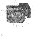
- Fig. 1 the holding jaw unit 1 according to the invention for a fastening element power supply, in particular for a stand-up tool, shown in the closed ground state.
- the holding jaw unit 1 is used to receive a via a corresponding transport device 5 (for reasons of clarity, only one half shown) supplied and previously isolated fastener 3, which has a fastener head 3a and a fastener element shaft 3b.
- the fastening element 3 may optionally, as shown here, also comprise a disk 3c pressed onto the fastening element head 3a.
- a sealing washer 13 can furthermore be applied to the fastening element shaft 3b.
- the holding jaw unit 1 has at least two holding jaws 2 and a holding jaw actuating arrangement 4, wherein the holding jaws 2 comprise an opening 6, which is open in the transport direction of the fastening element, for inserting the fastening element 3 and a recess 7 for receiving the fastening element head 3a.
- the opening 6 and the recess 7 define two bearing surfaces 14, of which the fastener head 3a is kept in the closed state.
- the opening 6 corresponds at least to the nominal diameter of the fastening element 3 or the diameter of the part of the fastening element shaft 3b adjacent to the pressed-on disk 3c.
- the depression 7 corresponds at least to the corner dimension of the fastener element head 3a or at least to the diameter of the washer 3c pressed onto the fastener element head 3a.
- the holding jaw actuating arrangement 4 is arranged. This can be actuated by a guided inside the device mandrel 8 (see. Fig. 3 ).
- the transport device 5 has a curved guideway 10 for the fastening element 3, in which the fastening element 3 slides from the separating element 15, which is rotatably mounted inside the device, into the closed holding jaws 2.
- the curved guide track 10 is divided into two by a web 11, wherein in the upper part of the guide track 10 a of the fastener head 3 a and the pressed-disc 3 c slide and in the The lower part of the guide track 10, the sealing disc 13.
- the web 11 is located on the between the pressed-disc 3c and the sealing washer 13 located part of the fastener element shaft 3b.
- Below the holding jaw unit 1 is a mouthpiece assembly 9 of the setting tool, in the mouthpiece 16, the fastening means 3 can be kept centered for the assembly process.
- the fastening element 3 has been transferred from the guideway 10 of the transport device 5 in the opening 6 of the closed holding jaws 2.
- the head 3a of the fastening element 3 together with the pressed-on disc 3c was received by the recess 7, so that the pressed-on disc 3c rests on the bearing surfaces 14.
- the thickness of the opening 6 corresponds to the length of the part of the fastener shank 3b, which runs between the top of the sealing washer 13 and the underside of the pressed disc 3c. That is, the wall thickness of the opening 6 corresponds approximately to the wall thickness of the web 11.
- the fastening element 3 is held by the holding jaw unit 1 centered along the axis X of the setting device.
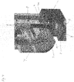
- the mandrel 8 in the axial direction X ie, parallel to the axis X of the setting tool, has moved down relative to the holding jaw unit 1, but has not yet engaged the rear engaging portion 4a of the holding jaw actuating assembly 4.
- the relative or downward movement of the mandrel 8 is brought about by a downward movement of the setting device.
- an operator exerts a compressive force on a grip part (not shown) of the setting device, which is coupled with the mandrel 8 and possibly also the drive train 12 in a suitable manner.
- the drive train 12 can also be moved downwards in order to engage with the fastener element head 3a.
- the holding jaw unit 1 assumes the same position as in the Fig. 1 and 2 ,
- Fig. 4 illustrates how the holding jaws 2 are actuated by means of the mandrel 8, when the mandrel 8 by a (further) relative to the holding jaw unit 1 in the axial direction X (ie parallel to the X-axis of the setting device) with the holding jaw actuating assembly 4 is engaged is, and thereby causes an opening movement of the holding jaws 2 in the horizontal direction Y (within the plane of the holding jaws).
- the mandrel 8 is pressed into the rear engaging portion 4a of the holding jaw actuating assembly 4
- at least one spring element (not shown) connected to the holding jaws 2 is actuated. By actuating this spring element, the holding jaws 2 are pulled apart in the horizontal direction Y.
- the opening 6 is thereby enlarged such that the pressed onto the fastener head 3a disc 3c and possibly also the drive train 12 of the setting device can pass through them.
- the centered fastener 3 may then fall into, for example, the funnel-shaped mouthpiece 16 in the mouthpiece assembly 9, where it is kept centered until it is assembled by the drive train 12.
- the diameter of the mouthpiece 16 is accordingly slightly larger than the diameter of the sealing disc 13.
- the sealing disc 13 rests against the conical walls of the mouthpiece 16, so that the fastening element 3 can not tilt.
- the unopened holding jaw unit 1 preferably leads according to FIG Fig. 3 First, a downward movement and inserts the fastener 3 in the mouthpiece 16, before the holding jaws 2 are opened, ie before the mandrel 8 is pressed into the rear engaging portion 4a of the holding jaw actuating assembly 4 and before the drive train 12 engages with the fastener element head 3a.
- the holding jaw unit 1 is arranged in this case in a suitable manner in the axial direction X movable within the setting device. This downward movement, if appropriate, can be carried out by the holding jaw unit together with the mandrel 8 and the drive train 12, which are then decoupled from the holding jaw unit 1 in a suitable manner.
Landscapes
- Engineering & Computer Science (AREA)
- Mechanical Engineering (AREA)
- Slide Fasteners (AREA)
- Mounting, Exchange, And Manufacturing Of Dies (AREA)
- Automatic Assembly (AREA)
- Portable Nailing Machines And Staplers (AREA)
Claims (11)
- Unité à mâchoires de retenue (1) pour un appareil de pose d'éléments de fixation, en particulier pour un outil utilisé debout, destiné à loger un élément de fixation (3) amené par l'intermédiaire d'un dispositif de transport correspondant (5) et comportant une tête d'élément de fixation (3a) et une tige d'élément de fixation (3b), munie d'au moins deux mâchoires de retenue (2) ainsi que d'un agencement de manoeuvre des mâchoires de retenue (4), les mâchoires de retenue (2) présentant une ouverture (6) pour l'introduction d'un élément de fixation (3) ainsi qu'un renfoncement (7) pour le logement de la tête d'élément de fixation (3a),
caractérisée en ce que
les mâchoires de retenue (2) peuvent être manoeuvrées à l'aide d'un mandrin (8), le mandrin (8) pouvant entrer en prise avec l'agencement de manoeuvre (4) des mâchoires de retenue grâce à un déplacement relatif dans la direction axiale par rapport à l'unité de mâchoires de retenue (1), ce qui provoque un déplacement de l'ouverture des mâchoires de retenue (2) dans la direction horizontale Y, l'ouverture (6) subissant un agrandissement tel qu'une barre d'entrainement (12) de l'appareil de pose puisse traverser les mâchoires de retenue (2), le mandrin (8) étant alors dissocié de la barre d'entrainement (12), et la barre d'entrainement (12) exerçant lors de sa traversée, au moins d'une manière temporaire, un déplacement relatif découplé du mandrin. - Unité à mâchoires de retenue (1) selon la revendication 1, caractérisée en ce que l'ouverture (6) correspond au moins au diamètre nominal de l'élément de fixation (3).
- Unité à mâchoires de retenue (1) selon l'une des revendications précédentes, caractérisée en ce que le renfoncement (7) correspond au moins à l'ouverture angulaire de la tête d'élément de fixation (3a), ou mais au moins au diamètre d'un disque (3c) qui est appuyé contre la tête d'élément de fixation (3a).
- Unité à mâchoires de retenue (1) selon l'une des revendications précédentes, caractérisée en ce que le déplacement relatif du mandrin (8) est provoqué par le déplacement de recul de l'appareil de pose.
- Unité à mâchoires de retenue (1) selon l'une des revendications précédentes, caractérisée en ce que le déplacement de l'ouverture des mâchoires de retenue (2) correspond au moins à l'ouverture angulaire de la tête d'élément de fixation (3a), ou mais au moins au diamètre d'un disque (3c) qui est appuyé contre la tête d'élément de fixation (3a).
- Unité à mâchoires de retenue (1) selon l'une des revendications précédentes, caractérisée en ce que l'unité de mâchoires de retenue (1) est disposée dans la direction axiale X de façon à pouvoir se déplacer à l'intérieur de l'appareil de pose.
- Unité à mâchoires de retenue (1) selon la revendication 6, caractérisée en ce que, sous l'effet d'un déplacement de recul dans la direction axiale X de l'unité de mâchoires de retenue (1) non ouverte, l'élément de fixation (3) peut être inséré dans un agencement d'embouchure (9) de l'appareil de pose.
- Unité de mâchoires de retenue (1) selon l'une des revendications précédentes, caractérisée en ce que le dispositif de transport (5) est muni d'un chemin de guidage incurvé (10) pour l'élément de fixation (3).
- Unité à mâchoires de retenue (1) selon la revendication 8, caractérisée en ce que le chemin de guidage incurvé (10) est divisé en deux par une traverse (11).
- Unité à mâchoires de retenue (1) selon l'une des revendications précédentes, caractérisée en ce que les éléments de fixation (3) sont munis d'un disque d'étanchéité (13) disposé sur la tige d'élément de fixation (3b).
- Unité à mâchoires de retenue (1) selon l'une des revendications précédentes, caractérisée en ce que la venue en prise du mandrin (8) dans l'agencement (4) de manoeuvre des mâchoires de retenue manoeuvre au moins un élément de ressort relié aux mâchoires de retenue (2).
Priority Applications (1)
| Application Number | Priority Date | Filing Date | Title |
|---|---|---|---|
| PL12195624T PL2610033T3 (pl) | 2011-12-27 | 2012-12-05 | Jednostka szczęk mocujących |
Applications Claiming Priority (1)
| Application Number | Priority Date | Filing Date | Title |
|---|---|---|---|
| DE102011089954A DE102011089954A1 (de) | 2011-12-27 | 2011-12-27 | Haltebackeneinheit |
Publications (3)
| Publication Number | Publication Date |
|---|---|
| EP2610033A2 EP2610033A2 (fr) | 2013-07-03 |
| EP2610033A3 EP2610033A3 (fr) | 2015-08-05 |
| EP2610033B1 true EP2610033B1 (fr) | 2019-09-11 |
Family
ID=47290749
Family Applications (1)
| Application Number | Title | Priority Date | Filing Date |
|---|---|---|---|
| EP12195624.7A Not-in-force EP2610033B1 (fr) | 2011-12-27 | 2012-12-05 | Unité de mâchoires de fixation |
Country Status (3)
| Country | Link |
|---|---|
| EP (1) | EP2610033B1 (fr) |
| DE (1) | DE102011089954A1 (fr) |
| PL (1) | PL2610033T3 (fr) |
Family Cites Families (6)
| Publication number | Priority date | Publication date | Assignee | Title |
|---|---|---|---|---|
| DE190951C (fr) * | ||||
| US3662797A (en) * | 1970-06-18 | 1972-05-16 | Behring Corp | Screwdriving apparatus |
| US3929176A (en) * | 1974-10-25 | 1975-12-30 | Dixon Babette | Machine for automatically driving threaded fasteners |
| DE4407155A1 (de) * | 1994-03-04 | 1995-09-07 | Joerg R Bauer | Vorrichtung zum Beschicken eines Schraubendrehers mit Schrauben |
| DE10305041A1 (de) | 2003-02-07 | 2004-08-19 | Hilti Ag | Zwischenfestlegung |
| FR2898069B1 (fr) * | 2006-03-02 | 2008-05-23 | L R Etanco Soc Par Actions Sim | Appareil pour le vissage, semi-automatique, d'elements de fixation |
-
2011
- 2011-12-27 DE DE102011089954A patent/DE102011089954A1/de not_active Withdrawn
-
2012
- 2012-12-05 PL PL12195624T patent/PL2610033T3/pl unknown
- 2012-12-05 EP EP12195624.7A patent/EP2610033B1/fr not_active Not-in-force
Non-Patent Citations (1)
| Title |
|---|
| None * |
Also Published As
| Publication number | Publication date |
|---|---|
| DE102011089954A1 (de) | 2013-08-29 |
| EP2610033A3 (fr) | 2015-08-05 |
| PL2610033T3 (pl) | 2020-01-31 |
| EP2610033A2 (fr) | 2013-07-03 |
Similar Documents
| Publication | Publication Date | Title |
|---|---|---|
| DE3448219C2 (fr) | ||
| EP0003004B1 (fr) | Dispositif pour placer des vis avec des rondelles | |
| DE2823766C3 (de) | Spannfutter | |
| EP0633825B1 (fr) | Dispositif d'amenee de pieces d'assemblage | |
| EP2632629B1 (fr) | Dispositif de positionnement et d'amenée d'éléments de fixation | |
| DE102009049616B4 (de) | Setzgerät, Zuführmodul des Setzgeräts und Fügeverfahren zum Verbinden von mindestens zwei Bauteilen | |
| EP1366304A2 (fr) | Rivet autoperforant, procede et dispositif pour poser un element rivet et utilisation de ce dernier | |
| EP2608905B1 (fr) | Appareil de rivetage avec collecte des tiges cassées | |
| EP2476518B1 (fr) | Unité d'insertion d'un élément de fixation | |
| EP1799390B1 (fr) | Mandrin pour serrer des elements de fixation pour une liaison de soudage par friction | |
| DE102013006315A1 (de) | Kleinteil-Vereinzelungsverfahren und -vorrichtung | |
| DE102013008653B4 (de) | Verfahren und Werkzeug zum Setzen von Blindnietmuttern | |
| DE19506336C2 (de) | An eine Antriebseinheit anbaubare Vorrichtung zum Eindrehen von Schrauben | |
| EP2208579A1 (fr) | Dispositif de retenue pour moyen de fixation | |
| DE102013012075B4 (de) | Restbehälter für Stückabfälle, insbesondere für Restdorne von Blindnieten | |
| EP1445069B1 (fr) | Dispositif de mise-en-place intermédiaire | |
| DE10208865B4 (de) | Werkzeug zum Bereitstellen von Blindnietmuttern sowie Vorrichtung zum Einbringen von Blindnietmuttern in Werkstücke mit einem solchen Bereitstellungswerkzeug | |
| DE10035427B4 (de) | Vorrichtung zum Eindrücken von Schrauben | |
| EP2610033A2 (fr) | Unité de mâchoires de fixation | |
| DE19928703B4 (de) | Verfahren und Vorrichtung zur Herstellung eines Bolzens | |
| EP1305126A1 (fr) | Dispositif et procede pour charger un module de rivetage avec des rivets borgnes cassables a mandrin ou avec des rivets creux | |
| DE102006045394B4 (de) | Einschraubvorrichtung und Vereinzelungsverfahren für Befestigungselemente | |
| DE19536350A1 (de) | Werkzeug zum Herausdrehen und Herausziehen von Bolzen aus Schnellverschlüssen | |
| DE10102694C1 (de) | Vorrichtung zum Einschrauben von magaziniert vorbereiteten Befestigungselementen | |
| DE69209355T2 (de) | Einrichtung für eine Maschine zum Eintreiben von Nägeln |
Legal Events
| Date | Code | Title | Description |
|---|---|---|---|
| PUAI | Public reference made under article 153(3) epc to a published international application that has entered the european phase |
Free format text: ORIGINAL CODE: 0009012 |
|
| AK | Designated contracting states |
Kind code of ref document: A2 Designated state(s): AL AT BE BG CH CY CZ DE DK EE ES FI FR GB GR HR HU IE IS IT LI LT LU LV MC MK MT NL NO PL PT RO RS SE SI SK SM TR |
|
| AX | Request for extension of the european patent |
Extension state: BA ME |
|
| PUAL | Search report despatched |
Free format text: ORIGINAL CODE: 0009013 |
|
| AK | Designated contracting states |
Kind code of ref document: A3 Designated state(s): AL AT BE BG CH CY CZ DE DK EE ES FI FR GB GR HR HU IE IS IT LI LT LU LV MC MK MT NL NO PL PT RO RS SE SI SK SM TR |
|
| AX | Request for extension of the european patent |
Extension state: BA ME |
|
| RIC1 | Information provided on ipc code assigned before grant |
Ipc: B25B 23/10 20060101ALI20150702BHEP Ipc: B25B 23/04 20060101AFI20150702BHEP Ipc: B25B 23/06 20060101ALI20150702BHEP |
|
| 17P | Request for examination filed |
Effective date: 20150817 |
|
| RBV | Designated contracting states (corrected) |
Designated state(s): AL AT BE BG CH CY CZ DE DK EE ES FI FR GB GR HR HU IE IS IT LI LT LU LV MC MK MT NL NO PL PT RO RS SE SI SK SM TR |
|
| 17Q | First examination report despatched |
Effective date: 20151123 |
|
| GRAP | Despatch of communication of intention to grant a patent |
Free format text: ORIGINAL CODE: EPIDOSNIGR1 |
|
| STAA | Information on the status of an ep patent application or granted ep patent |
Free format text: STATUS: GRANT OF PATENT IS INTENDED |
|
| INTG | Intention to grant announced |
Effective date: 20190426 |
|
| GRAS | Grant fee paid |
Free format text: ORIGINAL CODE: EPIDOSNIGR3 |
|
| GRAA | (expected) grant |
Free format text: ORIGINAL CODE: 0009210 |
|
| STAA | Information on the status of an ep patent application or granted ep patent |
Free format text: STATUS: THE PATENT HAS BEEN GRANTED |
|
| AK | Designated contracting states |
Kind code of ref document: B1 Designated state(s): AL AT BE BG CH CY CZ DE DK EE ES FI FR GB GR HR HU IE IS IT LI LT LU LV MC MK MT NL NO PL PT RO RS SE SI SK SM TR |
|
| REG | Reference to a national code |
Ref country code: GB Ref legal event code: FG4D Free format text: NOT ENGLISH Ref country code: DE Ref legal event code: R082 Ref document number: 502012015280 Country of ref document: DE Representative=s name: BARDEHLE PAGENBERG PARTNERSCHAFT MBB PATENTANW, DE |
|
| REG | Reference to a national code |
Ref country code: CH Ref legal event code: EP Ref country code: CH Ref legal event code: NV Representative=s name: HEPP WENGER RYFFEL AG, CH |
|
| REG | Reference to a national code |
Ref country code: AT Ref legal event code: REF Ref document number: 1177837 Country of ref document: AT Kind code of ref document: T Effective date: 20190915 |
|
| REG | Reference to a national code |
Ref country code: DE Ref legal event code: R096 Ref document number: 502012015280 Country of ref document: DE |
|
| REG | Reference to a national code |
Ref country code: IE Ref legal event code: FG4D Free format text: LANGUAGE OF EP DOCUMENT: GERMAN |
|
| REG | Reference to a national code |
Ref country code: NL Ref legal event code: FP |
|
| REG | Reference to a national code |
Ref country code: LT Ref legal event code: MG4D |
|
| PG25 | Lapsed in a contracting state [announced via postgrant information from national office to epo] |
Ref country code: LT Free format text: LAPSE BECAUSE OF FAILURE TO SUBMIT A TRANSLATION OF THE DESCRIPTION OR TO PAY THE FEE WITHIN THE PRESCRIBED TIME-LIMIT Effective date: 20190911 Ref country code: FI Free format text: LAPSE BECAUSE OF FAILURE TO SUBMIT A TRANSLATION OF THE DESCRIPTION OR TO PAY THE FEE WITHIN THE PRESCRIBED TIME-LIMIT Effective date: 20190911 Ref country code: BG Free format text: LAPSE BECAUSE OF FAILURE TO SUBMIT A TRANSLATION OF THE DESCRIPTION OR TO PAY THE FEE WITHIN THE PRESCRIBED TIME-LIMIT Effective date: 20191211 Ref country code: NO Free format text: LAPSE BECAUSE OF FAILURE TO SUBMIT A TRANSLATION OF THE DESCRIPTION OR TO PAY THE FEE WITHIN THE PRESCRIBED TIME-LIMIT Effective date: 20191211 Ref country code: SE Free format text: LAPSE BECAUSE OF FAILURE TO SUBMIT A TRANSLATION OF THE DESCRIPTION OR TO PAY THE FEE WITHIN THE PRESCRIBED TIME-LIMIT Effective date: 20190911 Ref country code: HR Free format text: LAPSE BECAUSE OF FAILURE TO SUBMIT A TRANSLATION OF THE DESCRIPTION OR TO PAY THE FEE WITHIN THE PRESCRIBED TIME-LIMIT Effective date: 20190911 |
|
| REG | Reference to a national code |
Ref country code: SK Ref legal event code: T3 Ref document number: E 32608 Country of ref document: SK |
|
| PG25 | Lapsed in a contracting state [announced via postgrant information from national office to epo] |
Ref country code: RS Free format text: LAPSE BECAUSE OF FAILURE TO SUBMIT A TRANSLATION OF THE DESCRIPTION OR TO PAY THE FEE WITHIN THE PRESCRIBED TIME-LIMIT Effective date: 20190911 Ref country code: GR Free format text: LAPSE BECAUSE OF FAILURE TO SUBMIT A TRANSLATION OF THE DESCRIPTION OR TO PAY THE FEE WITHIN THE PRESCRIBED TIME-LIMIT Effective date: 20191212 Ref country code: LV Free format text: LAPSE BECAUSE OF FAILURE TO SUBMIT A TRANSLATION OF THE DESCRIPTION OR TO PAY THE FEE WITHIN THE PRESCRIBED TIME-LIMIT Effective date: 20190911 Ref country code: AL Free format text: LAPSE BECAUSE OF FAILURE TO SUBMIT A TRANSLATION OF THE DESCRIPTION OR TO PAY THE FEE WITHIN THE PRESCRIBED TIME-LIMIT Effective date: 20190911 Ref country code: ES Free format text: LAPSE BECAUSE OF FAILURE TO SUBMIT A TRANSLATION OF THE DESCRIPTION OR TO PAY THE FEE WITHIN THE PRESCRIBED TIME-LIMIT Effective date: 20190911 |
|
| PG25 | Lapsed in a contracting state [announced via postgrant information from national office to epo] |
Ref country code: EE Free format text: LAPSE BECAUSE OF FAILURE TO SUBMIT A TRANSLATION OF THE DESCRIPTION OR TO PAY THE FEE WITHIN THE PRESCRIBED TIME-LIMIT Effective date: 20190911 Ref country code: PT Free format text: LAPSE BECAUSE OF FAILURE TO SUBMIT A TRANSLATION OF THE DESCRIPTION OR TO PAY THE FEE WITHIN THE PRESCRIBED TIME-LIMIT Effective date: 20200113 Ref country code: RO Free format text: LAPSE BECAUSE OF FAILURE TO SUBMIT A TRANSLATION OF THE DESCRIPTION OR TO PAY THE FEE WITHIN THE PRESCRIBED TIME-LIMIT Effective date: 20190911 |
|
| PG25 | Lapsed in a contracting state [announced via postgrant information from national office to epo] |
Ref country code: SM Free format text: LAPSE BECAUSE OF FAILURE TO SUBMIT A TRANSLATION OF THE DESCRIPTION OR TO PAY THE FEE WITHIN THE PRESCRIBED TIME-LIMIT Effective date: 20190911 Ref country code: IS Free format text: LAPSE BECAUSE OF FAILURE TO SUBMIT A TRANSLATION OF THE DESCRIPTION OR TO PAY THE FEE WITHIN THE PRESCRIBED TIME-LIMIT Effective date: 20200224 |
|
| REG | Reference to a national code |
Ref country code: DE Ref legal event code: R097 Ref document number: 502012015280 Country of ref document: DE |
|
| PLBE | No opposition filed within time limit |
Free format text: ORIGINAL CODE: 0009261 |
|
| STAA | Information on the status of an ep patent application or granted ep patent |
Free format text: STATUS: NO OPPOSITION FILED WITHIN TIME LIMIT |
|
| PG2D | Information on lapse in contracting state deleted |
Ref country code: IS |
|
| PG25 | Lapsed in a contracting state [announced via postgrant information from national office to epo] |
Ref country code: DK Free format text: LAPSE BECAUSE OF FAILURE TO SUBMIT A TRANSLATION OF THE DESCRIPTION OR TO PAY THE FEE WITHIN THE PRESCRIBED TIME-LIMIT Effective date: 20190911 Ref country code: CZ Free format text: LAPSE BECAUSE OF NON-PAYMENT OF DUE FEES Effective date: 20191205 Ref country code: IS Free format text: LAPSE BECAUSE OF FAILURE TO SUBMIT A TRANSLATION OF THE DESCRIPTION OR TO PAY THE FEE WITHIN THE PRESCRIBED TIME-LIMIT Effective date: 20200112 |
|
| REG | Reference to a national code |
Ref country code: CH Ref legal event code: PL |
|
| REG | Reference to a national code |
Ref country code: NL Ref legal event code: MM Effective date: 20200101 |
|
| 26N | No opposition filed |
Effective date: 20200615 |
|
| REG | Reference to a national code |
Ref country code: BE Ref legal event code: MM Effective date: 20191231 |
|
| PG25 | Lapsed in a contracting state [announced via postgrant information from national office to epo] |
Ref country code: SI Free format text: LAPSE BECAUSE OF FAILURE TO SUBMIT A TRANSLATION OF THE DESCRIPTION OR TO PAY THE FEE WITHIN THE PRESCRIBED TIME-LIMIT Effective date: 20190911 Ref country code: MC Free format text: LAPSE BECAUSE OF FAILURE TO SUBMIT A TRANSLATION OF THE DESCRIPTION OR TO PAY THE FEE WITHIN THE PRESCRIBED TIME-LIMIT Effective date: 20190911 |
|
| GBPC | Gb: european patent ceased through non-payment of renewal fee |
Effective date: 20191211 |
|
| REG | Reference to a national code |
Ref country code: SK Ref legal event code: MM4A Ref document number: E 32608 Country of ref document: SK Effective date: 20191205 |
|
| PG25 | Lapsed in a contracting state [announced via postgrant information from national office to epo] |
Ref country code: NL Free format text: LAPSE BECAUSE OF NON-PAYMENT OF DUE FEES Effective date: 20200101 |
|
| PG25 | Lapsed in a contracting state [announced via postgrant information from national office to epo] |
Ref country code: GB Free format text: LAPSE BECAUSE OF NON-PAYMENT OF DUE FEES Effective date: 20191211 Ref country code: IE Free format text: LAPSE BECAUSE OF NON-PAYMENT OF DUE FEES Effective date: 20191205 Ref country code: LU Free format text: LAPSE BECAUSE OF NON-PAYMENT OF DUE FEES Effective date: 20191205 Ref country code: IT Free format text: LAPSE BECAUSE OF NON-PAYMENT OF DUE FEES Effective date: 20191205 Ref country code: FR Free format text: LAPSE BECAUSE OF NON-PAYMENT OF DUE FEES Effective date: 20191231 Ref country code: SK Free format text: LAPSE BECAUSE OF NON-PAYMENT OF DUE FEES Effective date: 20191205 |
|
| PG25 | Lapsed in a contracting state [announced via postgrant information from national office to epo] |
Ref country code: CH Free format text: LAPSE BECAUSE OF NON-PAYMENT OF DUE FEES Effective date: 20191231 Ref country code: LI Free format text: LAPSE BECAUSE OF NON-PAYMENT OF DUE FEES Effective date: 20191231 Ref country code: BE Free format text: LAPSE BECAUSE OF NON-PAYMENT OF DUE FEES Effective date: 20191231 |
|
| PG25 | Lapsed in a contracting state [announced via postgrant information from national office to epo] |
Ref country code: CY Free format text: LAPSE BECAUSE OF FAILURE TO SUBMIT A TRANSLATION OF THE DESCRIPTION OR TO PAY THE FEE WITHIN THE PRESCRIBED TIME-LIMIT Effective date: 20190911 |
|
| PG25 | Lapsed in a contracting state [announced via postgrant information from national office to epo] |
Ref country code: HU Free format text: LAPSE BECAUSE OF FAILURE TO SUBMIT A TRANSLATION OF THE DESCRIPTION OR TO PAY THE FEE WITHIN THE PRESCRIBED TIME-LIMIT; INVALID AB INITIO Effective date: 20121205 Ref country code: MT Free format text: LAPSE BECAUSE OF FAILURE TO SUBMIT A TRANSLATION OF THE DESCRIPTION OR TO PAY THE FEE WITHIN THE PRESCRIBED TIME-LIMIT Effective date: 20190911 |
|
| PG25 | Lapsed in a contracting state [announced via postgrant information from national office to epo] |
Ref country code: PL Free format text: LAPSE BECAUSE OF NON-PAYMENT OF DUE FEES Effective date: 20191205 |
|
| REG | Reference to a national code |
Ref country code: DE Ref legal event code: R082 Ref document number: 502012015280 Country of ref document: DE Representative=s name: BARDEHLE PAGENBERG PARTNERSCHAFT MBB PATENTANW, DE |
|
| PG25 | Lapsed in a contracting state [announced via postgrant information from national office to epo] |
Ref country code: MK Free format text: LAPSE BECAUSE OF FAILURE TO SUBMIT A TRANSLATION OF THE DESCRIPTION OR TO PAY THE FEE WITHIN THE PRESCRIBED TIME-LIMIT Effective date: 20190911 |
|
| PGFP | Annual fee paid to national office [announced via postgrant information from national office to epo] |
Ref country code: AT Payment date: 20231214 Year of fee payment: 12 |
|
| PGFP | Annual fee paid to national office [announced via postgrant information from national office to epo] |
Ref country code: DE Payment date: 20231221 Year of fee payment: 12 |
|
| PG25 | Lapsed in a contracting state [announced via postgrant information from national office to epo] |
Ref country code: TR Free format text: LAPSE BECAUSE OF NON-PAYMENT OF DUE FEES Effective date: 20191205 |
|
| REG | Reference to a national code |
Ref country code: DE Ref legal event code: R119 Ref document number: 502012015280 Country of ref document: DE |
|
| REG | Reference to a national code |
Ref country code: AT Ref legal event code: MM01 Ref document number: 1177837 Country of ref document: AT Kind code of ref document: T Effective date: 20241205 |
|
| PG25 | Lapsed in a contracting state [announced via postgrant information from national office to epo] |
Ref country code: DE Free format text: LAPSE BECAUSE OF NON-PAYMENT OF DUE FEES Effective date: 20250701 |
|
| PG25 | Lapsed in a contracting state [announced via postgrant information from national office to epo] |
Ref country code: AT Free format text: LAPSE BECAUSE OF NON-PAYMENT OF DUE FEES Effective date: 20241205 |