EP2610081A2 - Pneu - Google Patents
Pneu Download PDFInfo
- Publication number
- EP2610081A2 EP2610081A2 EP20120197103 EP12197103A EP2610081A2 EP 2610081 A2 EP2610081 A2 EP 2610081A2 EP 20120197103 EP20120197103 EP 20120197103 EP 12197103 A EP12197103 A EP 12197103A EP 2610081 A2 EP2610081 A2 EP 2610081A2
- Authority
- EP
- European Patent Office
- Prior art keywords
- shoulder
- land portion
- vehicle
- groove
- longitudinal groove
- Prior art date
- Legal status (The legal status is an assumption and is not a legal conclusion. Google has not performed a legal analysis and makes no representation as to the accuracy of the status listed.)
- Granted
Links
Images



Classifications
-
- B—PERFORMING OPERATIONS; TRANSPORTING
- B60—VEHICLES IN GENERAL
- B60C—VEHICLE TYRES; TYRE INFLATION; TYRE CHANGING; CONNECTING VALVES TO INFLATABLE ELASTIC BODIES IN GENERAL; DEVICES OR ARRANGEMENTS RELATED TO TYRES
- B60C11/00—Tyre tread bands; Tread patterns; Anti-skid inserts
- B60C11/03—Tread patterns
- B60C11/032—Patterns comprising isolated recesses
-
- B—PERFORMING OPERATIONS; TRANSPORTING
- B60—VEHICLES IN GENERAL
- B60C—VEHICLE TYRES; TYRE INFLATION; TYRE CHANGING; CONNECTING VALVES TO INFLATABLE ELASTIC BODIES IN GENERAL; DEVICES OR ARRANGEMENTS RELATED TO TYRES
- B60C11/00—Tyre tread bands; Tread patterns; Anti-skid inserts
- B60C11/03—Tread patterns
- B60C11/04—Tread patterns in which the raised area of the pattern consists only of continuous circumferential ribs, e.g. zig-zag
-
- B—PERFORMING OPERATIONS; TRANSPORTING
- B60—VEHICLES IN GENERAL
- B60C—VEHICLE TYRES; TYRE INFLATION; TYRE CHANGING; CONNECTING VALVES TO INFLATABLE ELASTIC BODIES IN GENERAL; DEVICES OR ARRANGEMENTS RELATED TO TYRES
- B60C11/00—Tyre tread bands; Tread patterns; Anti-skid inserts
- B60C11/03—Tread patterns
- B60C11/0304—Asymmetric patterns
-
- B—PERFORMING OPERATIONS; TRANSPORTING
- B60—VEHICLES IN GENERAL
- B60C—VEHICLE TYRES; TYRE INFLATION; TYRE CHANGING; CONNECTING VALVES TO INFLATABLE ELASTIC BODIES IN GENERAL; DEVICES OR ARRANGEMENTS RELATED TO TYRES
- B60C11/00—Tyre tread bands; Tread patterns; Anti-skid inserts
- B60C11/01—Shape of the shoulders between tread and sidewall, e.g. rounded, stepped or cantilevered
-
- B—PERFORMING OPERATIONS; TRANSPORTING
- B60—VEHICLES IN GENERAL
- B60C—VEHICLE TYRES; TYRE INFLATION; TYRE CHANGING; CONNECTING VALVES TO INFLATABLE ELASTIC BODIES IN GENERAL; DEVICES OR ARRANGEMENTS RELATED TO TYRES
- B60C11/00—Tyre tread bands; Tread patterns; Anti-skid inserts
- B60C11/03—Tread patterns
-
- B—PERFORMING OPERATIONS; TRANSPORTING
- B60—VEHICLES IN GENERAL
- B60C—VEHICLE TYRES; TYRE INFLATION; TYRE CHANGING; CONNECTING VALVES TO INFLATABLE ELASTIC BODIES IN GENERAL; DEVICES OR ARRANGEMENTS RELATED TO TYRES
- B60C11/00—Tyre tread bands; Tread patterns; Anti-skid inserts
- B60C11/03—Tread patterns
- B60C11/0306—Patterns comprising block rows or discontinuous ribs
-
- B—PERFORMING OPERATIONS; TRANSPORTING
- B60—VEHICLES IN GENERAL
- B60C—VEHICLE TYRES; TYRE INFLATION; TYRE CHANGING; CONNECTING VALVES TO INFLATABLE ELASTIC BODIES IN GENERAL; DEVICES OR ARRANGEMENTS RELATED TO TYRES
- B60C11/00—Tyre tread bands; Tread patterns; Anti-skid inserts
- B60C11/03—Tread patterns
- B60C11/11—Tread patterns in which the raised area of the pattern consists only of isolated elements, e.g. blocks
-
- B—PERFORMING OPERATIONS; TRANSPORTING
- B60—VEHICLES IN GENERAL
- B60C—VEHICLE TYRES; TYRE INFLATION; TYRE CHANGING; CONNECTING VALVES TO INFLATABLE ELASTIC BODIES IN GENERAL; DEVICES OR ARRANGEMENTS RELATED TO TYRES
- B60C11/00—Tyre tread bands; Tread patterns; Anti-skid inserts
- B60C11/03—Tread patterns
- B60C11/12—Tread patterns characterised by the use of narrow slits or incisions, e.g. sipes
-
- B—PERFORMING OPERATIONS; TRANSPORTING
- B60—VEHICLES IN GENERAL
- B60C—VEHICLE TYRES; TYRE INFLATION; TYRE CHANGING; CONNECTING VALVES TO INFLATABLE ELASTIC BODIES IN GENERAL; DEVICES OR ARRANGEMENTS RELATED TO TYRES
- B60C11/00—Tyre tread bands; Tread patterns; Anti-skid inserts
- B60C11/03—Tread patterns
- B60C11/13—Tread patterns characterised by the groove cross-section, e.g. for buttressing or preventing stone-trapping
-
- B—PERFORMING OPERATIONS; TRANSPORTING
- B60—VEHICLES IN GENERAL
- B60C—VEHICLE TYRES; TYRE INFLATION; TYRE CHANGING; CONNECTING VALVES TO INFLATABLE ELASTIC BODIES IN GENERAL; DEVICES OR ARRANGEMENTS RELATED TO TYRES
- B60C11/00—Tyre tread bands; Tread patterns; Anti-skid inserts
- B60C11/03—Tread patterns
- B60C11/13—Tread patterns characterised by the groove cross-section, e.g. for buttressing or preventing stone-trapping
- B60C11/1369—Tie bars for linking block elements and bridging the groove
-
- B—PERFORMING OPERATIONS; TRANSPORTING
- B60—VEHICLES IN GENERAL
- B60C—VEHICLE TYRES; TYRE INFLATION; TYRE CHANGING; CONNECTING VALVES TO INFLATABLE ELASTIC BODIES IN GENERAL; DEVICES OR ARRANGEMENTS RELATED TO TYRES
- B60C11/00—Tyre tread bands; Tread patterns; Anti-skid inserts
- B60C11/03—Tread patterns
- B60C2011/0337—Tread patterns characterised by particular design features of the pattern
- B60C2011/0339—Grooves
- B60C2011/0341—Circumferential grooves
-
- B—PERFORMING OPERATIONS; TRANSPORTING
- B60—VEHICLES IN GENERAL
- B60C—VEHICLE TYRES; TYRE INFLATION; TYRE CHANGING; CONNECTING VALVES TO INFLATABLE ELASTIC BODIES IN GENERAL; DEVICES OR ARRANGEMENTS RELATED TO TYRES
- B60C11/00—Tyre tread bands; Tread patterns; Anti-skid inserts
- B60C11/03—Tread patterns
- B60C2011/0337—Tread patterns characterised by particular design features of the pattern
- B60C2011/0339—Grooves
- B60C2011/0341—Circumferential grooves
- B60C2011/0348—Narrow grooves, i.e. having a width of less than 4 mm
-
- B—PERFORMING OPERATIONS; TRANSPORTING
- B60—VEHICLES IN GENERAL
- B60C—VEHICLE TYRES; TYRE INFLATION; TYRE CHANGING; CONNECTING VALVES TO INFLATABLE ELASTIC BODIES IN GENERAL; DEVICES OR ARRANGEMENTS RELATED TO TYRES
- B60C11/00—Tyre tread bands; Tread patterns; Anti-skid inserts
- B60C11/03—Tread patterns
- B60C2011/0337—Tread patterns characterised by particular design features of the pattern
- B60C2011/0339—Grooves
- B60C2011/0341—Circumferential grooves
- B60C2011/0353—Circumferential grooves characterised by width
-
- B—PERFORMING OPERATIONS; TRANSPORTING
- B60—VEHICLES IN GENERAL
- B60C—VEHICLE TYRES; TYRE INFLATION; TYRE CHANGING; CONNECTING VALVES TO INFLATABLE ELASTIC BODIES IN GENERAL; DEVICES OR ARRANGEMENTS RELATED TO TYRES
- B60C11/00—Tyre tread bands; Tread patterns; Anti-skid inserts
- B60C11/03—Tread patterns
- B60C2011/0337—Tread patterns characterised by particular design features of the pattern
- B60C2011/0339—Grooves
- B60C2011/0358—Lateral grooves, i.e. having an angle of 45 to 90 degees to the equatorial plane
- B60C2011/036—Narrow grooves, i.e. having a width of less than 3 mm
-
- B—PERFORMING OPERATIONS; TRANSPORTING
- B60—VEHICLES IN GENERAL
- B60C—VEHICLE TYRES; TYRE INFLATION; TYRE CHANGING; CONNECTING VALVES TO INFLATABLE ELASTIC BODIES IN GENERAL; DEVICES OR ARRANGEMENTS RELATED TO TYRES
- B60C11/00—Tyre tread bands; Tread patterns; Anti-skid inserts
- B60C11/03—Tread patterns
- B60C2011/0337—Tread patterns characterised by particular design features of the pattern
- B60C2011/0339—Grooves
- B60C2011/0358—Lateral grooves, i.e. having an angle of 45 to 90 degees to the equatorial plane
- B60C2011/0367—Lateral grooves, i.e. having an angle of 45 to 90 degees to the equatorial plane characterised by depth
- B60C2011/0369—Lateral grooves, i.e. having an angle of 45 to 90 degees to the equatorial plane characterised by depth with varying depth of the groove
-
- B—PERFORMING OPERATIONS; TRANSPORTING
- B60—VEHICLES IN GENERAL
- B60C—VEHICLE TYRES; TYRE INFLATION; TYRE CHANGING; CONNECTING VALVES TO INFLATABLE ELASTIC BODIES IN GENERAL; DEVICES OR ARRANGEMENTS RELATED TO TYRES
- B60C11/00—Tyre tread bands; Tread patterns; Anti-skid inserts
- B60C11/03—Tread patterns
- B60C2011/0337—Tread patterns characterised by particular design features of the pattern
- B60C2011/0339—Grooves
- B60C2011/0381—Blind or isolated grooves
-
- B—PERFORMING OPERATIONS; TRANSPORTING
- B60—VEHICLES IN GENERAL
- B60C—VEHICLE TYRES; TYRE INFLATION; TYRE CHANGING; CONNECTING VALVES TO INFLATABLE ELASTIC BODIES IN GENERAL; DEVICES OR ARRANGEMENTS RELATED TO TYRES
- B60C11/00—Tyre tread bands; Tread patterns; Anti-skid inserts
- B60C11/03—Tread patterns
- B60C2011/0337—Tread patterns characterised by particular design features of the pattern
- B60C2011/0386—Continuous ribs
-
- B—PERFORMING OPERATIONS; TRANSPORTING
- B60—VEHICLES IN GENERAL
- B60C—VEHICLE TYRES; TYRE INFLATION; TYRE CHANGING; CONNECTING VALVES TO INFLATABLE ELASTIC BODIES IN GENERAL; DEVICES OR ARRANGEMENTS RELATED TO TYRES
- B60C11/00—Tyre tread bands; Tread patterns; Anti-skid inserts
- B60C11/03—Tread patterns
- B60C2011/0337—Tread patterns characterised by particular design features of the pattern
- B60C2011/0386—Continuous ribs
- B60C2011/0388—Continuous ribs provided at the equatorial plane
-
- B—PERFORMING OPERATIONS; TRANSPORTING
- B60—VEHICLES IN GENERAL
- B60C—VEHICLE TYRES; TYRE INFLATION; TYRE CHANGING; CONNECTING VALVES TO INFLATABLE ELASTIC BODIES IN GENERAL; DEVICES OR ARRANGEMENTS RELATED TO TYRES
- B60C11/00—Tyre tread bands; Tread patterns; Anti-skid inserts
- B60C11/03—Tread patterns
- B60C2011/0337—Tread patterns characterised by particular design features of the pattern
- B60C2011/0386—Continuous ribs
- B60C2011/039—Continuous ribs provided at the shoulder portion
-
- B—PERFORMING OPERATIONS; TRANSPORTING
- B60—VEHICLES IN GENERAL
- B60C—VEHICLE TYRES; TYRE INFLATION; TYRE CHANGING; CONNECTING VALVES TO INFLATABLE ELASTIC BODIES IN GENERAL; DEVICES OR ARRANGEMENTS RELATED TO TYRES
- B60C11/00—Tyre tread bands; Tread patterns; Anti-skid inserts
- B60C11/03—Tread patterns
- B60C2011/0337—Tread patterns characterised by particular design features of the pattern
- B60C2011/0386—Continuous ribs
- B60C2011/0393—Narrow ribs, i.e. having a rib width of less than 8 mm
-
- B—PERFORMING OPERATIONS; TRANSPORTING
- B60—VEHICLES IN GENERAL
- B60C—VEHICLE TYRES; TYRE INFLATION; TYRE CHANGING; CONNECTING VALVES TO INFLATABLE ELASTIC BODIES IN GENERAL; DEVICES OR ARRANGEMENTS RELATED TO TYRES
- B60C11/00—Tyre tread bands; Tread patterns; Anti-skid inserts
- B60C11/03—Tread patterns
- B60C11/12—Tread patterns characterised by the use of narrow slits or incisions, e.g. sipes
- B60C11/1236—Tread patterns characterised by the use of narrow slits or incisions, e.g. sipes with special arrangements in the tread pattern
- B60C2011/1254—Tread patterns characterised by the use of narrow slits or incisions, e.g. sipes with special arrangements in the tread pattern with closed sipe, i.e. not extending to a groove
Definitions
- the present invention relates to a pneumatic tire capable of improving drainage performance, on-snow performance, and on-ice performance, while maintaining steering stability on a dry road surface.
- a pneumatic tire (which is also referred to as an all-season tire) with improved driving performance for a dry road surface as well as an icy or snowy road and the like has been known.
- This type of tire has a tread portion including multiple blocks which are sectioned by circumferentially extending longitudinal grooves and axially extending lateral grooves.
- Such longitudinal grooves and lateral grooves can smoothly discharge a water film interposed between the tire and a road surface.
- the longitudinal and lateral grooves can dig into a snowy road and obtain snow column shearing force. Consequently, the drainage performance and on-ice performance are improved.
- axi all y extending si pes are provided in the blocks. Edges of such sipes can generate considerable friction force on an icy road, thereby improving the on-ice performance. Listed below are related technologies.
- Patent Document 1 Japanese Patent Application Publication No. 2008-6987
- the present invention has been made in view of the actual circumstances as described above, and it is a main object of the present invention to provide a pneumatic tire capable of improving the drainage performance, on-snow performance, and on-ice performance while maintaining the steering stability on a dry road surface.
- a first aspect of the present invention is a pneumatic tire having a designated mounting orientation with respect to a vehicle, wherein a tread portion includes a pair of center longitudinal grooves which continuously extends in a circumferential direction on both sides of a tire equator and a pair of shoulder longitudinal grooves which continuously extends in the circumferential direction on both sides of the pair of center longitudinal grooves,
- the pair of center longitudinal grooves consists of an outer center longitudinal groove and an inner center longitudinal groove, the outer center longitudinal groove and the inner center longitudinal groove being respectively located on an outer side and an inner si de of the vehi cl e when the ti re is mounted to the vehi cl e
- the pair of shoul der longitudinal grooves consists of an outer shoulder longitudinal groove disposed on the vehicle outer side of the outer center longitudinal groove and an inner shoulder longitudinal groove disposed on a vehicle inner side of the inner center longitudinal groove
- the tread portion is divided into:
- dimensions of respective parts of a tire are values specified in an unloaded standard state in which a tire is mounted around a standard rim and filled with a standard internal pressure.
- the "standard rim” is a rim defined for each tire by a standard in a standard system including the standard on which the tire is based. For example, it means a normal rim in JATMA, "Design Rim” in TRA, and “Measuring Rim” in ETRTO.
- the "standard internal pressure” is an air pressure defined by the standard for each tire, and shall be a maximum air pressure in JATMA, a maximum value described in the table "TIRE LOAD LIMITS AT VARIOUS COLD INFLATION PRESSURES" in TRA, and "INFLATION PRESSURE” in ETRTO. It shall be 180 kPa for a tire for a passenger vehicle.
- a pneumatic tire of the present invention is a tire having a designated mounting orientation with respect to a vehicle, and having a tread portion in which are provided a pair of center longitudinal grooves which continuously extend in a circumferential direction on both sides of a tire equator and a pair of shoulder longitudinal grooves which continuously extend in the circumferential direction on both sides of the pair of center longitudinal grooves.
- the pair of center longitudinal grooves consists of an outer center longitudinal groove and an inner center longitudinal groove, the outer center longitudinal groove and the inner center longitudinal groove being respectively located on an outer side and an inner side of the vehicle when a tire is mounted to the vehicle.
- the pair of shoulder longitudinal grooves consists of an outer shoulder longitudinal groove disposed on a vehicle outer side of the outer center longitudinal groove and an inner shoulder longitudinal groove disposed on a vehicle inner side of the inner center longitudinal groove.
- the tread portion is further divided into a center land portion located between the pair of center longitudinal grooves, an outer middle land portion located between the outer center longitudinal groove and the outer shoulder longitudinal groove, an inner middle land portion located between the inner center longitudinal groove and the inner shoulder longitudinal groove, an outer shoulder land portion located on the vehicle outer side of the outer shoulder longitudinal groove , and an inner shoulder land portion located on the vehicle inner side of the inner shoulder longitudinal groove.
- the outer shoulder land portion includes outer shoulder lateral grooves which extend from a vehicle-outer-side tread ground-contact end to the inner side of the vehicle and traverse the outer shoulder land portion.
- the outer shoulder lateral grooves divide the outer shoulder land portion into multiple outer shoulder blocks.
- the outer shoulder lateral grooves allow a water film between the tire and a road surface to be discharged smoothly.
- the outer shoulder lateral grooves dig into a snowy road, the snow column shearing force is obtained, thereby improving the drainage performance and on-snow performance.
- the inner shoulder land portion includes inner shoulder lateral grooves and inner shoulder auxiliary grooves.
- the inner shoulder lateral grooves extend to the outer si de of the vehi cl e from an inner end which is spaced from the vehicle-inner-side tread ground-contact end, and the outer end terminates within the inner shoulder land portion.
- the inner shoulder auxiliary grooves are disposed between the inner shoul der lateral grooves whi ch are circumferentially adjacent to each other, extending to the outer side of the vehicle from an inner end which is spaced from the vehicle-inner side tread ground-contact end, and having the outer end terminating within the inner shoulder land portion.
- the inner middle land potion includes an inner middle sub-groove and inner middle sipes.
- the inner middle sub-groove continuously extends in the circumferential direction at a position on a vehicle inner side of a width center of the inner middle land portion.
- the inner middle sipes extend between the inner middle sub-groove and inner center longitudinal groove with an inclination with respect to the circumferential direction.
- a pneumatic tire 1 of the embodi ment (which may be simply referred to as a tire hereinafter) is constituted as so-called an all-season tire having improved driving performance on a dry road surface as well as an icy or snowy road, for example.
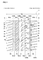
- a tread portion 2 of the tire 1 includes a pair of center longitudinal grooves 3 which continuously extends in a circumferential direction on both sides of a tire equator C and a pair of shoulder longitudinal grooves 4 which continuously extends in the ci rcumferenti al direction on both sides of the pair of center longitudinal grooves 3.
- the tread portion 2 includes lateral grooves 5 which extend in a direction intersecting with the center longitudinal grooves 3 and the shoulder longitudinal grooves 4 and are provided at intervals in the circumferential direction.
- the center longitudinal grooves 3 consist of an outer center longitudinal groove 3A and an inner center longitudinal groove 3B, the outer center longitudinal groove 3A and the inner center longitudinal groove 3B being respectively located on an outer side and an inner si de of the vehi cl e when a tire is mounted to the vehicle.
- the shoulder longitudinal grooves 4 consist of an outer shoulder longitudinal groove 4A disposed on a vehicle outer side of the outer center longitudinal groove 3A and an inner shoulder longitudinal groove 4B disposed on the vehicle inner side of the inner center longitudinal groove 3B.
- the outer center longitudinal groove 3A and the inner center longitudinal groove 3B are formed as a straight groove linearly extending in the circumferential direction. With such an outer center longitudinal groove 3A and an inner center longitudinal groove 3B, a water film between the tread portion 2 and a road surface is smoothly guided to the circumferential direction in a neighborhood of the ti re equator C. Additionally, the outer center longitudinal groove 3A and the inner center longitudinal groove 3B dig into a snowy road and snow column shearing force is obtained. This improves drainage performance and on-snow performance.
- a groove width w1a of the outer center longitudinal groove 3A and a grove width w1b of the inner center longitudinal groove 3B are in the range of 4 to 10% of a tread ground-contact width TW, which is an axial distance between tread ground-contact ends 2t, 2t. It is also preferable that a maximum groove depth D1a (as shown in Fig. 2 ) of the outer center longitudinal groove 3A and a maximum groove depth D1b of the inner center longitudinal groove 3B (as shown in Fig. 2 ) are in the range of 6 to 10 mm.
- the "tread ground-contact end 2t" shall be an axial outermost end of a tread ground-contact surface when the ti re 1 in a state in which it is mounted on the standard rim and filled with the standard internal pressure is given normal load and brought into contact with a flat surface at a camber angle of 0 degree.
- the "normal load” is a load defined for each tire by the standard, and is a maximum air pressure in JATMA, a maximum value described in the table "TIRE LOAD LIMITS AT VARIOUS COLD INFLATION PRESSURES" in TRA, and "LOAD CAPACITY" in ETRTO.
- the groove width w1a of the outer center longitudinal groove 3A is set larger than the groove width w1b of the inner center longitudinal groove 3B.
- the outer center longitudinal groove 3A improves the drainage performance and on-snow performance when a vehicle travels in a straight line or when it is revolving in which a ground-contact pressure of the outer side of the vehicle increases.
- a ratio (w1a/w1b) of the groove width w1a of the outer center longitudinal groove 3A to the groove width w1b of the inner center longitudinal groove 3B is preferably 105 to 120%.
- the outer shoulder longitudinal groove 4A and the inner shoulder longitudinal groove 4B are also formed as a straight groove. This improves the drainage performance and on-snow performance. It is preferable that a groove width w1c of the outer shoulder longitudinal groove 4A and a groove width w1d of the inner shoulder longitudinal groove 4B are in the range of 3 to 8% of the tread ground-contact width TW. It is preferable that a maximum groove depth D1c (as shown in Fig. 2 ) of the outer shoulder longitudinal groove 4A and a maximum groove depth D1d (as shown in Fig. 2 ) of the inner shoulder longitudinal groove 4B are in the range of 6 to 10 mm.
- the groove width w1c of the outer shoulder longitudinal groove 4A is set smaller than the groove widths w1a, w1b of the pair of center longitudinal grooves 3A, 3B and the groove width w1d of the inner shoulder longitudinal groove 4B. This increases a land ratio of the tread portion 2 on the outer side of the vehicle, and improves the steering stability and wear resistance.
- a ratio (w1c/w1a) of the groove width w1c of the outer shoulder longitudinal groove 4A to the groove width w1a of the outer center longitudinal groove 3A is preferably 30 to 70%.
- the lateral grooves 5 include outer shoulder lateral grooves 5A and outer middle lateral grooves 5B.
- the outer shoulder lateral grooves 5A Crossing the outer shoulder land portion 8A, the outer shoulder lateral grooves 5A extend from the vehicle-outer-side tread ground-contact end 2t to the inner side of the vehicle.
- vehicle-inner-side inner ends 5Ai of the outer shoulder lateral grooves 5A terminate within the outer middle land portion 7A.
- the outer middle lateral grooves 5B extend to the inner side of the vehicle from vehicle-outer-side outer ends 5Bo which are located in the outer middle land portion 7A.
- vehicle-inner-side inner ends 5Bi of the outer middle lateral grooves 5B terminate within the center land portion 6.
- outer shoulder lateral grooves 5A and outer middle lateral grooves 5B a water film between the tread portion 2 and a road surface is smoothly guided in the axial direction to the outer side of the tire, in a neighborhood of the tire equator C and in a region on a vehicle outer side of the tire equator C.
- the outer shoulder lateral grooves 5A and the outer middle lateral grooves 5B dig into a snowy road and snow column shearing force is obtained. This improves the drainage performance and on-ice performance.
- a grove width w2 of the outer shoulder lateral grooves 5A and a groove width w3 of the outer middle lateral grooves 5B are in the range of 1 to 4% of the tread ground-contact width TW. It is preferable that a groove depth D2 (as shown in Fig. 2 ) of the outer shoulder lateral grooves 5A and a groove depth D3 (as shown in Fig. 2 ) of the outer middle lateral grooves 5B are in the range of 6 to 10 mm.
- the inner ends 5Ai of the outer shoulder lateral grooves 5A are circumferentially shifted from the outer ends 5 Bo of the outer middle lateral grooves 5B.
- the inner ends 5Ai of the outer shoulder lateral grooves 5A are disposed on a vehicle outer side of the outer ends 5Bo of the outer middle lateral grooves 5B.
- Such outer shoulder lateral grooves 5A and outer middle lateral grooves 5B prevent deterioration in rigidity of the outer middle land portion 7A. This improves the steering stability and wear resistance. It is preferable that a circumferential distance L1a between the inner ends 5Ai of the outer shoulder lateral grooves 5A and the outer ends 5Bo of the outer middle lateral grooves 5B is in the range of 5 to 10 mm. It is also preferable that an axial distance L1b between the inner ends 5Ai and the outer ends 5Bo is in the range of 2 to 5 mm.
- the distances L1a, L1b are values measured on center lines 5Ac, 5Bc of the outer shoul der lateral grooves 5A and the outer middle lateral grooves 5B.
- a lower limit of the distance L1a is more preferably 6 mm or more, and an upper limit thereof is more preferably 9 mm or smaller.
- a lower limit of the distance L1b is more preferably 3 mm or more and an upper limit thereof is more preferably 4 mm or less.
- the outer shoulder lateral grooves 5A of the embodiment smoothly bend and extend while gradually increasing an angle ⁇ 1a to the circumferential direction.
- the angle ⁇ 1a is preferably 60 to 90 degrees.
- Such outer shoulder lateral grooves 5A ensure lateral rigidity of the outer shoulder land portion 8A. This improves the steering stability on a dry road surface.
- the outer shoulder lateral grooves 5A have tie bars 9a, 9b disposed on both sides of the outer shoulder longitudinal groove 4A.
- the tie bars 9a, 9b reduce the groove depth D2 by raised groove bottom 5Ab.
- Such tie bars 9a, 9b can reduce a circumferential rigidity step in a vehicle-outer-side region in the outer middle land portion 7A and a vehicle-inner-side regi on in the outer shoul der land porti on 8A where uneven wear tends to occur. This improves uneven wear resistance and wear resistance.
- axial lengths L2a, L2b of the tie bars 9a, 9b are in the range of 2 to 14 mm.
- heights H2a, H2b from the groove bottom 5Ab of the tie bars 9a, 9b is 2 to 6 mm.
- a groove depth D2i at the vehicle-inner-side inner ends 5Ai of the outer shoulder lateral grooves 5A are made larger than a groove depth D2o of the tie bars 9b. This allows groove volume, which tends to be reduced by the tie bars 9b, to be ensured in the outer middle land portion 7A, thereby improving the drainage performance and on-ice performance.
- a ratio (D2i/D2o) of the groove depth D2i to the groove depth D2o is preferably 150 to 200%.
- the outer middle lateral grooves 5B of the embodiment smoothly bend and extend while gradually increasing an angle ⁇ 1b to the circumferential direction.
- the angle ⁇ 1b is preferably 50 to 70 degrees and set smaller than the angle ⁇ 1a of the outer shoulder lateral grooves 5A.
- Such outer middle lateral grooves 5B ensure circumferential rigidity of the center land portion 6 and the outer middle land portion 7A. This improves straight running stability performance.
- the groove width w3 and the groove depth D3 of the outer middle lateral grooves 5B gradually decrease from the outer center longitudinal groove 3A to the inner ends 5Bi.
- Such outer middle lateral grooves 5B ensure rigidity of the region on the side of the tire equator C whose ground-contact pressure increases when a vehicle drives straight. This further improves the straight running stability performance.
- the outer middle lateral grooves 5B have tie bars 9c on the vehicle outer side of the outer center longitudinal groove 3A.
- the tie bars 9c reduce the groove depth D3 by a raised groove bottom 5Bb.
- Such tie bars 9c reduce a circumferential rigidity step in a vehicle-inner-side region in the outer middle land portion 7A. This improves the uneven wear resistance.
- axial length L2c and height H2c of the tie bars 9c are respectively in the same range as the length L2a, L2b and height H2a, H2b of the outer shoulder lateral grooves 5A.
- the center land portion 6 consists of a straight rib which linearly extends without interruption in the circumferential di rection on the ti re equator C. Such a center land portion 6 improves its circumferential rigidity. This enhances the straight running stability performance. It is preferable that a land portion width w3a of the center land portion 6 is 8 to 15% of the tread ground-contact width TW.
- the center land portion 6 includes center sipes 12 between the outer middle lateral grooves 5B which are circumferentially adjacent to each other.
- the center sipes 12 bend and extend from a vehicle-outer-side outer end 6o of the center land portion 6, while gradually decreasing an angle ⁇ 1c to the circumferential direction.
- the center sipes 12 intersect with one side of the outer middle lateral grooves 5B in a neighborhood of the ti re equator C.
- Such center si pes 12 suppress excessive deterioration in rigidity of the center land portion 6. Yet, since edges work in the axial and circumferential directions, the wear resistance and on-ice performance improve.
- the outer middle land portion 7A has a land portion width w3b larger than a land portion width w3c of the inner middle land portion 7B.
- Such an outer middle land portion 7A increases a land ratio on the outer side of the vehicle. This improves the steering stability, uneven wear resistance, and wear resistance on a dry road surface.
- a ratio (w3b/w3c) of the land portion width w3b to the land portion width w3c is preferably 105 to 130%.
- the outer middle land portion 7A includes outer middle thin grooves 13.
- the outer middle thin grooves 13 connect the inner ends 5Ai of the outer shoulder lateral grooves 5A with the outer ends 5Bo of the outer middle lateral grooves 5B.
- the outer shoulder lateral grooves 5A, the outer middle lateral grooves 5B, and the outer middle thin grooves 13 divide the outer middle land portion 7A into multiple circumferentially arranged outer middle blocks 15.
- An orientation of inclination of the outer middle thin grooves to the circumferential direction is opposite to that of inclination of the outer shoulder lateral grooves 5A and of the outer middle lateral grooves 5B.
- a groove width of the outer middle thin grooves 13 is smaller than the groove width of the outer shoulder lateral grooves 5A and the outer middle lateral grooves 5B.
- outer middle thin grooves 13 allow edges to work in a well-balanced manner on the circumferential and axial directions. This improves the on-ice performance. Furthermore, both groove walls of the outer mi ddl e thin grooves 13 come into contact wi th each other due to lateral force from a road surface at the time of revolution in which a ground-contact pressure of the outer middle land portion 7A increases. With this, the outer middle blocks 15, 15, which are circumferentially adjacent to each other, are mutually supported. Thus, rigidity of the outer middle land portion 7A is improved, and the steering stability, uneven wear resistance, and wear resistance on a dry road surface are improved.
- a length L4 of the outer middle thin groves 13 is preferably 2.0 to 8.0 mm.
- a lower limit of the length L4 is preferably 4.0 mm or more and an upper limit thereof is preferably 7.0 mm or less.
- An angle ⁇ 2a of the outer middle thin grooves 13 to the circumferential direction is preferably 20 to 40 degrees. If the angle ⁇ 2a is less than 20 degrees, it is possible that the edge effect is not produced adequately in the circumferential direction. To the contrary, even if the angle ⁇ 2a exceeds 40 degrees, the edge effect may not be produced adequately in the circumferential direction. From such a viewpoint, a lower limit of the angle ⁇ 2a is preferably 25 degrees or more and an upper limit thereof is preferably 37 degrees or less.
- the outer mi ddl e blocks 15 include outer mi ddl e si pes 16 whi ch extend from a vehicle-inner-side inner edge 15i to the outer side of the vehicle.
- the outer middle sipes 16 extend linearly from an almost intermediate position of the inner edge 15i in the circumferential direction wi th an inclination angle ⁇ 2b whi ch is the same as the angle ⁇ 1b (as shown in Fig. 1 ) of the outer middle lateral grooves 5B.
- vehicle-outer-side outer ends 16o of the outer middle sipes 16 terminate within the outer middle land portion 7A.
- Such outer middle si pes 16 not only suppress the deterioration in rigidity of the outer middle blocks 15 but also improve the on-ice performance.
- the inner middle land portion 7B consists of a straight rib which linearly extends in the circumferential direction. With such an inner middle land portion 7B, its lateral rigidity is adequately maintained even if the land portion width w3c is smaller than the land portion width w3b, as described above. This improves the steering stability on a dry road surface.
- the inner middle land portion 7B includes an inner middle sub-groove 18, inner middle sipes 21, inner middle slots 19, and extended sipes 20.
- an inner middle thin rib 25 is formed which prevents arrangement of a sipe and the like.
- the inner middle sub-groove 18 continuously extends in the circumferential direction in the inner middle land portion 7B.
- the inner middle sub-groove 18 is located on the vehicle inner side of the width center of the inner middle land portion 7B. with such an inner middle sub-groove 18, a water film between the inner middle land portion7B and a road surface is smoothly guided to the circumferential direction. Yet, the circumferential edge improves the drainage performance and on-ice performance.
- a groove width w5a of the inner middle sub-groove 18 is 5 to 10% of the land portion width w3c (as shown in Fig. 1 ) of the inner middle land portion 7B.
- a groove depth D5a (as shown in Fig. 2 ) of the inner middle sub-groove 18 is 1 to 4 mm.
- the inner middle sipes 21 extend between the inner middle sub-groove 18 and the inner center longitudinal groove 3B with an inclination with respect to the circumferential direction.
- the inner middle sipes 21 bend and extend from the inner center longitudinal groove 3B to the inner middle sub-groove 18, while gradually increasing an angle ⁇ 3a to the circumferential direction.
- Such inner middle sipes 21 allow edge thereof to work from the circumferential to axial direction, thereby improving the on-ice performance.
- the angle ⁇ 3a of the inner middle si pes 21 is 20 to 60 degrees. If the angle ⁇ 3a is less than 20 degrees, the edge effect is not produced adequately on the circumferential direction. Thus, it is possible that the on-ice performance may not be improved adequately. To the contrary, even if the angle ⁇ 3a exceeds 60 degrees, the edge effect is not produced adequately on the axial direction. From such a viewpoint, a lower limit of the angle ⁇ 3a is preferably 30 degrees or more and an upper limit thereof is preferably 50 degrees or less.
- the inner middle slots 19 extend from the inner center longitudinal groove 3B to the inner side of the vehicle, between the inner middle sipes 21, 21 which are circumferentially adjacent to each other.
- the inner middle slots 19 extend from an almost center of the circumferential direction between the inner middle sipes 21, 21 which are circumferentially adjacent to each other, wi th an inclination angle ⁇ 3b of, for example, 20 to 60 degrees, with respect to the circumferential direction.
- Vehicle-inner-side inner ends 19i of the inner middle slots 19 terminate without reaching the inner middle sub-groove 18.
- a groove width w5b and a groove depth D5b (as shown in Fig. 2 ) of the inner middle slots 19 gradually decrease from the inner middle longitudinal groove 3B to the inner ends 19i.
- Such inner middle slots 19 not only suppress the deterioration in rigidity of the inner middle land portion 7B but also improve the drainage performance and on-ice performance.
- the groove width w5b of the inner middle slots 19 is preferably 5 to 9 mm and the groove depth D5b of the inner middle slots 19 is preferably 5 to 9 mm.
- the extended sipes 20 extend from the inner ends 19i of the inner middle slots 19 with an inclination to the inner side of the vehicle. It is preferable that an angle of inclination ⁇ 3c of the extended si pes 20 to the circumferential direction is in the almost same angle range as the angle ⁇ 3b of the inner middle slots 19. vehicle-inner-side inner ends 20i of the extended si pes 20 terminate without reaching the inner middle sub-groove 18.
- Such extended sipes 20 not only suppress the deterioration in ri gi di ty of the inner middle land portion 7B but also improve the on-ice performance.
- the inner middle thin rib 25 continuously extends in the circumferential direction on the vehicle inner side of the inner middle sub-groove 18. Such an inner middle thin rib 25 improves lateral rigidity of the vehicle inner side. This improves the steering stability on a dry road surface. It is preferable that a ratio (w5c/w3c) of a rib width w5c of the inner middle thin rib 25 to the land portion width w3c of the inner middle land portion 7B is 20 to 40%.
- a lower limit of the ratio (w5c/w3c) is preferably 25% or more and an upper limit thereof is preferably 35% or less.
- a land portion width w3d of the outer shoulder land portion 8A is larger than a land portion width w3e of the inner shoulder land portion 8B.
- a land ratio can be increased on the vehicle outer side of the tread portion 2 in which a ground-contact pressure increases at the time of revolution. This improves the steering stability, uneven wear resistance, and wear resistance on a dry road surface.
- a ratio (w3d/w3e) of the land portion width w3d of the outer shoul der land portion 8A to the land portion width w3e of the inner shoulder land portion 8B is preferably 101 to 110%.
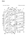
- the outer shoulder land portion 8A is divided by the outer shoulder lateral grooves 5A into multiple circumferentially arranged outer shoulder blocks 22. As shown in Fig. 3 in a close-up manner, the outer shoulder blocks 22 have circumferential sipes 23 and outer shoulder sipes 24.
- the circumferential sipes 23 extend in the circumferential direction on the side of the outer shoulder longitudinal groove 4A. Both circumferential ends 23t of the circumferential sipes 23 terminate without reaching the outer shoulder lateral grooves 5A, 5A, which are circumferentially adjacent to each other. Such circumferential sipes 23 alleviate rigidity of the vehicle-inner-side region in the outer shoulder land portion 8A, thus reducing a circumferential rigidity step. In addition, the circumferential edge improves the uneven wear resistance and on-i ce performance.
- two or more (two in this example) circumferential sipes 23 are formed in a region T which is 2 to 14 mm spaced on the circumferentially outer side from the vehicle-inner-side inner edge 8Ai of the outer shoulder land portion 8A. with this, the multiple circumferential sipes 23 are disposed in the region T having the same length as the length L2a of the tie bars 9a.
- the circumferential rigidity step in the vehicle-inner-side region of the outer shoulder land portion 8A decreases, thereby further suppressing occurrence of uneven wear.
- the outer shoul der sipes 24 extend from the vehicle-outer-side tread ground-contact end 2t with an inclination to the inner side of the vehicle. It is preferable that an angle ⁇ 4a of inclination of the outer shoulder sipes 24 to the circumferential direction is in the same angle range as the angle ⁇ 1a (as shown in Fig. 1 ) of the outer shoulder lateral grooves 5A. with such outer shoulder sipes 24, the axial edge improves the on-ice performance.
- Inner ends 24i of the outer shoulder si pes 24 terminate without reaching the circumferential sipes 23 and the outer shoulder longitudinal groove 4A.
- Such outer shoulder sipes 24 suppress the deterioration in rigidity of the outer shoulder land portion 8A.
- the inner shoulder land portion 8B consists of a straight rib which linearly extends in the circumferential direction on the side of the vehicle-inner-side tread ground-contact end 2t. Such an inner shoulder land portion 8B improves its lateral rigidity and enhances the steering stability.
- the land portion width w3e of the inner shoulder land portion 8B is preferably 11 to 15% of the tread ground-contact width TW.
- the inner shoulder land portion 8B includes both inner shoulder lateral grooves 26 and inner shoulder auxiliary grooves 28.
- the inner shoulder lateral grooves 26 extend to the outer side of the vehicle from inner ends 26i which are spaced a distance L5a to the outer side of the vehicle from the vehicle-inner-side tread ground-contact and 2t.
- the inner shoulder lateral grooves 26 extend from the inner ends 26i with an inclination angle ⁇ 5a of, for example, 60 to 90 degrees, with respect to the circumferential direction.
- Vehicle-outer-side outer ends 26o of the inner shoulder lateral grooves 26 terminate within the inner shoulder land portion 8B.
- Such inner shoulder lateral grooves 26 not only suppress the deterioration in rigidity of the inner shoulder land portion 8B but also improve the drainage performance and on-snow performance.
- a groove width W6 of the inner shoulder lateral grooves 26 is 1 to 3% of the tread ground-contact width TW (as shown in Fig. 1 ). It is also preferable that a maximum groove depth D6 (as shown in Fig. 2 ) of the inner shoulder lateral grooves 26 is 6 to 10 mm.
- the distance L5a of the inner shoulder lateral grooves 26 is preferably 2.5 to 7.5 mm. If the distance L5a is less than 2.5 mm, it is possible that the rigidity of the inner shoulder land portion 8B is not maintained adequately, thereby making it impossible to adequately maintain the steering stability, wear resistance, and uneven wear resistance. To the contrary, if the distance L5a exceeds 7.5 mm, the inner shoulder lateral grooves 26 become short, thereby making it impossible to adequately maintain the drainage performance and on-snow performance. Similarly, the distance L5b from the outer ends 26o of the inner shoul der lateral grooves 26 to the inner shoul der longitudinal groove 4B is preferably 4 mm or more and preferably 7 mm or less.
- the outer ends 26o of the inner shoulder lateral grooves 26 are formed in a tapered shape. Such inner shoulder lateral grooves 26 can minimize the deterioration in rigidity of the inner shoulder land portion 8B.
- extended si pes 27 are di sposed, which extend between the vehicle-outer-side outer ends 26o of the inner shoulder lateral grooves 26 and the inner shoulder longitudinal groove 4B.
- the extended si pes 27 incline at an angle ⁇ 5b which is in the same angle range as that of the angle ⁇ 5a of the inner shoulder lateral grooves 26.
- the extended si pes 27 contribute to improvement in the drainage performance and on-ice performance.
- the inner shoulder auxiliary grooves 28 are formed between the inner shoulder lateral grooves 26, 26 whi ch are circumferentially adjacent to each other. Vehicle-inner-side inner ends 28i of the inner shoulder auxiliary grooves 28 are spaced a distance L6a from the vehicle-inner-side tread ground-contact end 2t to the outer side of the vehicle.
- the inner shoulder auxiliary groves 28 extend from the inner ends 28i, with an inclination angle ⁇ 5c which is in the same angle range as that of the angle ⁇ 5a of the inner shoul der lateral grooves 26.
- Vehicle-outer-side outer ends 28o of the inner shoul der auxiliary grooves 28 terminate within the inner shoul der land porti on 8B.
- Such inner shoulder auxiliary grooves 28 improve the drainage performance and on-ice performance, while maintaining the steering stability on a dry road surface.
- the distance L6a of the inner shoulder auxiliary grooves 28 is preferably 8 to 15 mm. If the distance L6a is less than 8 mm, it is possible that the steering stability, wear resistance, and uneven wear resistance may not be maintained adequately. To the contrary, if the distance L6a exceeds 15 mm, it is possible that the drainage performance and on-ice performance may not be maintained adequately.
- a distance L6b from the outer ends 28o of the inner shoulder auxiliary grooves 28 to the inner shoulder longitudinal groove 4B is preferably 3 mm or more and preferably 6 mm or less.
- Tires consisting of the basic structure shown in Fig. 1 and having longitudinal grooves, lateral grooves, and sipes as shown in Table 1 were manufactured and their performance was evaluated.
- a comparative example 1 as shown in Fig. 5A , comparative example 2 as shown in Fig. 5B , and comparative example 3 as shown in Fig. 5C were created for the purpose of comparison, and evaluated similarly.
- an inner shoulder land portion 8B is divided into blocks, it does not have inner shoul der auxiliary grooves 28.
- an outer shoulder land portion 8A consists of a straight rib.
- the comparative example 3 does not have an inner middle sub-groove 18 and inner middle sipes 21.
- common specifications shall be as follows:
- a test method is as follows:
- Each sample tire (tire size: 225/55R17) is mounted around a rim (rim size: 17 x 7.0JJ) , filled with internal pressure of 230 kPa, and mounted to all wheels of a domestically produced FR vehicle (4300 cc displacement). Then, on an asphalt road surface having water depth of 5 mm, full-braking was performed on the condition that ABS turns on from a speed of 60 km, and a braking distance was measured. The result is indicated with an index in whi ch the comparative example 1 is 100, for an inverse of the braking distance. The larger a numeric value is, the better the drainage performance is.
- Each sample tire (tire size: 195/65R15) is mounted around a rim (rim size: 15 x 6.0JJ) , filled with internal pressure of 230 kPa, and mounted to all wheels of a domestically produced FR vehicle (2000 cc displacement). Then, after driving on a dry asphalt road surface for 8000 km, groove depth of an outer center longitudinal groove and an outer shoulder longitudinal groove was measured. The measurement was performed on three positions on the circumference of each tire, and all average values were obtained. The result is indicated with an index in which the comparative example 1 is 100, for each average value. The larger a numeric value is, the better the wear resistance is.
- Each sample tire (tire size: 195/65R15) is mounted around a rim (rim size: 15 x 6.0JJ) , filled with internal pressure of 230 kPa, and mounted to all wheels of a domestically produced FR vehicle (2000 cc displacement). Then, after driving on a dry asphalt road surface for 8000 km, a difference in an amount of wear between circumferential inner edge and outer edge was measured in an outer middle land portion and an outer shoulder land portion. The measurement was performed on three positions on the circumference of each ti re, and all average val ues were obtained. The result is indicated wi th an index i n whi ch the comparative example 1 is 100, for an inverse of each average val ue. The larger a numeric value is, the better the uneven wear resistance is.
- Each sample tire (tire size: 225/55R17) is mounted around a rim (ri m size: 17 x 7.0JJ), filled with internal pressure of 230 kPa, and mounted to all wheels of a domestically produced FR vehicle (4300 cc displacement). Then, one driver drove the vehicle on a dry asphalt road surface of a test course. Then, the characteristics related to handle responsiveness, rigidity feel , and grip and the like were sensory evaluated by the professional driver. The result is indicated with a mark in which the comparative example 1 is 100. The larger a numeric value is, the better the steering stability is.
- Each sample tire (tire size: 225/55R17) is mounted around a rim (rim size: 17 x 7.0JJ) , filled with internal pressure of 230 kPa, and mounted to all wheels of a domestically produced FR vehicle (4300 cc displacement). Then, the vehi cl e was driven on icy and snowy road of a test course.
- the characteristics related to straight running stability, braking stability, handle responsiveness, rigidity feel, grip, and the like were sensory evaluated by a professional driver. The result is indicated with a mark in which the comparative example 1 is 100. The larger a numeric value is, the better the on-ice performance is.
- Table 1 shows test results. [Table 1-1] Comparative example 1 Comparative example 2 Comparative example 3 Example 1 Example 2 Example 3 Example 4 Example 5 Example 6 Example 7 Expansion plan of tread portion Fig. 5A Fig. 5B Fig. 5C Fig. 1 Fig. 1 Fig. 1 Fig. 1 Fig. 1 Fig. 1 Fig. 1 Fig. 1 Fig. 1 Fig. 1 Fig. 1 Fig. 1 Fig. 1 Fig.
- the ti re of the example could improve the drainage performance, on-snow performance, and on-ice performance while maintaining the steering stability on a dry road surface.
Landscapes
- Engineering & Computer Science (AREA)
- Mechanical Engineering (AREA)
- Tires In General (AREA)
Applications Claiming Priority (1)
| Application Number | Priority Date | Filing Date | Title |
|---|---|---|---|
| JP2011289679A JP5385968B2 (ja) | 2011-12-28 | 2011-12-28 | 空気入りタイヤ |
Publications (3)
| Publication Number | Publication Date |
|---|---|
| EP2610081A2 true EP2610081A2 (fr) | 2013-07-03 |
| EP2610081A3 EP2610081A3 (fr) | 2017-12-27 |
| EP2610081B1 EP2610081B1 (fr) | 2018-07-25 |
Family
ID=47355908
Family Applications (1)
| Application Number | Title | Priority Date | Filing Date |
|---|---|---|---|
| EP12197103.0A Not-in-force EP2610081B1 (fr) | 2011-12-28 | 2012-12-14 | Pneu |
Country Status (6)
| Country | Link |
|---|---|
| US (1) | US9061552B2 (fr) |
| EP (1) | EP2610081B1 (fr) |
| JP (1) | JP5385968B2 (fr) |
| KR (1) | KR101817364B1 (fr) |
| CN (1) | CN103182902B (fr) |
| RU (1) | RU2605808C2 (fr) |
Cited By (8)
| Publication number | Priority date | Publication date | Assignee | Title |
|---|---|---|---|---|
| CN107206847A (zh) * | 2015-01-30 | 2017-09-26 | 株式会社普利司通 | 充气轮胎 |
| CN107614288A (zh) * | 2015-06-08 | 2018-01-19 | 株式会社普利司通 | 轮胎 |
| EP3351407A1 (fr) * | 2017-01-18 | 2018-07-25 | Sumitomo Rubber Industries, Ltd. | Pneumatique |
| CN110315912A (zh) * | 2019-07-25 | 2019-10-11 | 寿光福麦斯轮胎有限公司 | 一种轿跑车用轮胎 |
| CN111699096A (zh) * | 2018-02-14 | 2020-09-22 | 横滨橡胶株式会社 | 充气轮胎 |
| EP4019283A1 (fr) * | 2020-12-28 | 2022-06-29 | Sumitomo Rubber Industries, Ltd. | Pneumatique |
| EP4166356A1 (fr) * | 2021-10-18 | 2023-04-19 | Sumitomo Rubber Industries, Ltd. | Pneumatique |
| EP4201708A1 (fr) * | 2021-12-27 | 2023-06-28 | Sumitomo Rubber Industries, Ltd. | Pneumatique |
Families Citing this family (29)
| Publication number | Priority date | Publication date | Assignee | Title |
|---|---|---|---|---|
| JP6148942B2 (ja) * | 2013-09-02 | 2017-06-14 | 東洋ゴム工業株式会社 | 空気入りタイヤ |
| US10195904B2 (en) * | 2014-05-29 | 2019-02-05 | Bridgestone Corporation | Pneumatic tire |
| JP5793227B1 (ja) * | 2014-08-06 | 2015-10-14 | 東洋ゴム工業株式会社 | 空気入りタイヤ |
| JP6534795B2 (ja) * | 2014-08-08 | 2019-06-26 | 株式会社ブリヂストン | 非空気入りタイヤ |
| AU361970S (en) * | 2014-10-21 | 2015-05-25 | Yokohama Rubber Co Ltd | Automobile tire |
| JP6006772B2 (ja) * | 2014-10-30 | 2016-10-12 | 住友ゴム工業株式会社 | 空気入りタイヤ |
| JP6332086B2 (ja) * | 2015-03-10 | 2018-05-30 | 横浜ゴム株式会社 | 空気入りタイヤ |
| JP6374826B2 (ja) * | 2015-04-09 | 2018-08-15 | 住友ゴム工業株式会社 | 空気入りタイヤ |
| JP6434857B2 (ja) * | 2015-05-12 | 2018-12-05 | 住友ゴム工業株式会社 | 空気入りタイヤ |
| JP2017024657A (ja) * | 2015-07-27 | 2017-02-02 | 横浜ゴム株式会社 | 空気入りタイヤ |
| USD796423S1 (en) | 2015-08-18 | 2017-09-05 | Bridgestone Americas Tire Operations, Llc | Tire tread |
| JP6699245B2 (ja) * | 2016-03-04 | 2020-05-27 | 住友ゴム工業株式会社 | 空気入りタイヤ |
| JP6711169B2 (ja) | 2016-06-24 | 2020-06-17 | 住友ゴム工業株式会社 | タイヤ |
| JP6828387B2 (ja) * | 2016-11-14 | 2021-02-10 | 住友ゴム工業株式会社 | タイヤ |
| JP6822095B2 (ja) * | 2016-11-24 | 2021-01-27 | 住友ゴム工業株式会社 | タイヤ |
| JP6891515B2 (ja) * | 2017-01-31 | 2021-06-18 | 住友ゴム工業株式会社 | タイヤ |
| JP6891624B2 (ja) * | 2017-05-02 | 2021-06-18 | 住友ゴム工業株式会社 | タイヤ |
| USD857613S1 (en) * | 2017-05-12 | 2019-08-27 | Pirelli Tyre S.P.A. | Car tire |
| JP6927806B2 (ja) * | 2017-08-31 | 2021-09-01 | Toyo Tire株式会社 | 空気入りタイヤ |
| JP7012515B2 (ja) * | 2017-11-17 | 2022-01-28 | Toyo Tire株式会社 | 空気入りタイヤ |
| JP2019093872A (ja) * | 2017-11-22 | 2019-06-20 | Toyo Tire株式会社 | 空気入りタイヤ |
| EP3489036B1 (fr) * | 2017-11-27 | 2020-05-20 | Sumitomo Rubber Industries Ltd. | Pneumatique |
| JP7052507B2 (ja) * | 2018-04-06 | 2022-04-12 | 住友ゴム工業株式会社 | タイヤ |
| JP7070180B2 (ja) * | 2018-07-12 | 2022-05-18 | 住友ゴム工業株式会社 | タイヤ |
| JP7206952B2 (ja) * | 2019-01-25 | 2023-01-18 | 住友ゴム工業株式会社 | タイヤ |
| JP6981509B1 (ja) * | 2020-08-24 | 2021-12-15 | 横浜ゴム株式会社 | タイヤ |
| JP7669790B2 (ja) * | 2021-05-18 | 2025-04-30 | 住友ゴム工業株式会社 | タイヤ |
| JP7711521B2 (ja) | 2021-09-21 | 2025-07-23 | 住友ゴム工業株式会社 | タイヤ |
| CN117103911A (zh) * | 2023-07-14 | 2023-11-24 | 山东玲珑轮胎股份有限公司 | 一种低滚阻优制动的轿车轮胎及其制备工艺 |
Citations (1)
| Publication number | Priority date | Publication date | Assignee | Title |
|---|---|---|---|---|
| JP2008006987A (ja) | 2006-06-29 | 2008-01-17 | Sumitomo Rubber Ind Ltd | 空気入りタイヤ |
Family Cites Families (19)
| Publication number | Priority date | Publication date | Assignee | Title |
|---|---|---|---|---|
| EP1189770B1 (fr) * | 1999-06-30 | 2004-01-14 | Pirelli Pneumatici Societa' Per Azioni | Pneumatique haute performance pour un vehicule automobile |
| JP2003326917A (ja) * | 2002-05-10 | 2003-11-19 | Toyo Tire & Rubber Co Ltd | 空気入りラジアルタイヤ |
| DE20216992U1 (de) * | 2002-11-04 | 2003-01-16 | Goodyear Dunlop Tires Germany GmbH, 63450 Hanau | Fahrzeugluftreifen, insbesondere Sommerreifen für Personenkraftwagen |
| JP2005138678A (ja) * | 2003-11-05 | 2005-06-02 | Yokohama Rubber Co Ltd:The | 空気入りタイヤ |
| JP4744800B2 (ja) * | 2003-12-05 | 2011-08-10 | 株式会社ブリヂストン | 空気入りタイヤ |
| JP4369734B2 (ja) * | 2003-12-09 | 2009-11-25 | 住友ゴム工業株式会社 | 空気入りタイヤ |
| US8267135B2 (en) * | 2004-09-24 | 2012-09-18 | Bridgestone Corporation | Pneumatic tire with tread having circumferential grooves and lug grooves |
| JP2006192929A (ja) * | 2005-01-11 | 2006-07-27 | Bridgestone Corp | 空気入りタイヤ |
| JP4786317B2 (ja) * | 2005-12-05 | 2011-10-05 | 株式会社ブリヂストン | 空気入りラジアルタイヤ |
| JP4954743B2 (ja) * | 2007-02-08 | 2012-06-20 | 東洋ゴム工業株式会社 | 空気入りタイヤ |
| JP4388569B2 (ja) * | 2007-08-01 | 2009-12-24 | 住友ゴム工業株式会社 | 空気入りタイヤ |
| JP4163244B1 (ja) * | 2007-08-08 | 2008-10-08 | 横浜ゴム株式会社 | 空気入りタイヤ |
| US8267132B2 (en) * | 2007-10-12 | 2012-09-18 | Bridgestone Corporation | Pneumatic tire |
| JP5290707B2 (ja) * | 2008-11-10 | 2013-09-18 | 東洋ゴム工業株式会社 | 空気入りタイヤ |
| EP2397343B1 (fr) * | 2009-02-10 | 2014-10-15 | Bridgestone Corporation | Pneu |
| JP4697336B2 (ja) * | 2009-02-20 | 2011-06-08 | 横浜ゴム株式会社 | 空気入りタイヤ |
| CN102770286B (zh) * | 2010-02-26 | 2015-12-16 | 株式会社普利司通 | 充气轮胎 |
| JP5714832B2 (ja) * | 2010-03-29 | 2015-05-07 | 株式会社ブリヂストン | タイヤ |
| JP5676320B2 (ja) * | 2011-03-14 | 2015-02-25 | 株式会社ブリヂストン | 空気入りタイヤ |
-
2011
- 2011-12-28 JP JP2011289679A patent/JP5385968B2/ja active Active
-
2012
- 2012-12-13 US US13/713,290 patent/US9061552B2/en active Active
- 2012-12-13 RU RU2012153757/11A patent/RU2605808C2/ru active
- 2012-12-14 EP EP12197103.0A patent/EP2610081B1/fr not_active Not-in-force
- 2012-12-17 KR KR1020120147114A patent/KR101817364B1/ko not_active Expired - Fee Related
- 2012-12-21 CN CN201210562652.5A patent/CN103182902B/zh active Active
Patent Citations (1)
| Publication number | Priority date | Publication date | Assignee | Title |
|---|---|---|---|---|
| JP2008006987A (ja) | 2006-06-29 | 2008-01-17 | Sumitomo Rubber Ind Ltd | 空気入りタイヤ |
Cited By (18)
| Publication number | Priority date | Publication date | Assignee | Title |
|---|---|---|---|---|
| EP3251877A4 (fr) * | 2015-01-30 | 2018-05-30 | Bridgestone Corporation | Bandage pneumatique |
| CN107206847A (zh) * | 2015-01-30 | 2017-09-26 | 株式会社普利司通 | 充气轮胎 |
| EP3498498A1 (fr) * | 2015-01-30 | 2019-06-19 | Bridgestone Corporation | Pneumatique |
| CN107206847B (zh) * | 2015-01-30 | 2019-08-27 | 株式会社普利司通 | 充气轮胎 |
| US10688830B2 (en) | 2015-01-30 | 2020-06-23 | Bridgestone Corporation | Pneumatic tire |
| CN107614288B (zh) * | 2015-06-08 | 2019-12-17 | 株式会社普利司通 | 轮胎 |
| CN107614288A (zh) * | 2015-06-08 | 2018-01-19 | 株式会社普利司通 | 轮胎 |
| EP3305552A4 (fr) * | 2015-06-08 | 2018-06-13 | Bridgestone Corporation | Pneumatique |
| EP3351407A1 (fr) * | 2017-01-18 | 2018-07-25 | Sumitomo Rubber Industries, Ltd. | Pneumatique |
| US10967681B2 (en) | 2017-01-18 | 2021-04-06 | Sumitomo Rubber Industries, Ltd. | Tire |
| CN111699096A (zh) * | 2018-02-14 | 2020-09-22 | 横滨橡胶株式会社 | 充气轮胎 |
| US11999195B2 (en) | 2018-02-14 | 2024-06-04 | The Yokohama Rubber Co., Ltd. | Pneumatic tire |
| CN110315912A (zh) * | 2019-07-25 | 2019-10-11 | 寿光福麦斯轮胎有限公司 | 一种轿跑车用轮胎 |
| CN110315912B (zh) * | 2019-07-25 | 2024-06-04 | 寿光福麦斯轮胎有限公司 | 一种轿跑车用轮胎 |
| EP4019283A1 (fr) * | 2020-12-28 | 2022-06-29 | Sumitomo Rubber Industries, Ltd. | Pneumatique |
| EP4166356A1 (fr) * | 2021-10-18 | 2023-04-19 | Sumitomo Rubber Industries, Ltd. | Pneumatique |
| EP4201708A1 (fr) * | 2021-12-27 | 2023-06-28 | Sumitomo Rubber Industries, Ltd. | Pneumatique |
| US12162313B2 (en) | 2021-12-27 | 2024-12-10 | Sumitomo Rubber Industries, Ltd. | Tire |
Also Published As
| Publication number | Publication date |
|---|---|
| EP2610081A3 (fr) | 2017-12-27 |
| JP5385968B2 (ja) | 2014-01-08 |
| RU2012153757A (ru) | 2014-06-20 |
| JP2013139166A (ja) | 2013-07-18 |
| KR20130076715A (ko) | 2013-07-08 |
| CN103182902B (zh) | 2016-08-03 |
| US20130167994A1 (en) | 2013-07-04 |
| EP2610081B1 (fr) | 2018-07-25 |
| RU2605808C2 (ru) | 2016-12-27 |
| KR101817364B1 (ko) | 2018-01-11 |
| US9061552B2 (en) | 2015-06-23 |
| CN103182902A (zh) | 2013-07-03 |
Similar Documents
| Publication | Publication Date | Title |
|---|---|---|
| EP2610081A2 (fr) | Pneu | |
| US10894446B2 (en) | Tire | |
| US10836215B2 (en) | Tire | |
| EP2591923B1 (fr) | Pneu | |
| EP2610082B1 (fr) | Pneu | |
| US10967681B2 (en) | Tire | |
| EP2752309B1 (fr) | Pneu | |
| US10272725B2 (en) | Pneumatic tire | |
| EP3263367B1 (fr) | Pneumatique | |
| US11001102B2 (en) | Tire | |
| EP2586628B1 (fr) | Pneu | |
| EP3015288B1 (fr) | Pneumatique | |
| US10118445B2 (en) | Pneumatic tire | |
| EP2514608A2 (fr) | Pneu | |
| US10780743B2 (en) | Tire | |
| EP3378678B1 (fr) | Pneumatique | |
| EP3693187B1 (fr) | Pneumatique | |
| EP3747672A1 (fr) | Bande de roulement de pneumatique | |
| JP2013103567A (ja) | 空気入りタイヤ | |
| EP4556259A1 (fr) | Pneumatique | |
| EP3988337B1 (fr) | Pneumatique | |
| EP4335662A1 (fr) | Pneumatique | |
| EP3936351A1 (fr) | Pneumatique |
Legal Events
| Date | Code | Title | Description |
|---|---|---|---|
| PUAI | Public reference made under article 153(3) epc to a published international application that has entered the european phase |
Free format text: ORIGINAL CODE: 0009012 |
|
| AK | Designated contracting states |
Kind code of ref document: A2 Designated state(s): AL AT BE BG CH CY CZ DE DK EE ES FI FR GB GR HR HU IE IS IT LI LT LU LV MC MK MT NL NO PL PT RO RS SE SI SK SM TR |
|
| AX | Request for extension of the european patent |
Extension state: BA ME |
|
| PUAL | Search report despatched |
Free format text: ORIGINAL CODE: 0009013 |
|
| AK | Designated contracting states |
Kind code of ref document: A3 Designated state(s): AL AT BE BG CH CY CZ DE DK EE ES FI FR GB GR HR HU IE IS IT LI LT LU LV MC MK MT NL NO PL PT RO RS SE SI SK SM TR |
|
| AX | Request for extension of the european patent |
Extension state: BA ME |
|
| RIC1 | Information provided on ipc code assigned before grant |
Ipc: B60C 11/12 20060101ALN20171120BHEP Ipc: B60C 11/03 20060101AFI20171120BHEP Ipc: B60C 11/13 20060101ALN20171120BHEP |
|
| STAA | Information on the status of an ep patent application or granted ep patent |
Free format text: STATUS: REQUEST FOR EXAMINATION WAS MADE |
|
| 17P | Request for examination filed |
Effective date: 20180201 |
|
| RBV | Designated contracting states (corrected) |
Designated state(s): AL AT BE BG CH CY CZ DE DK EE ES FI FR GB GR HR HU IE IS IT LI LT LU LV MC MK MT NL NO PL PT RO RS SE SI SK SM TR |
|
| RIC1 | Information provided on ipc code assigned before grant |
Ipc: B60C 11/03 20060101AFI20180227BHEP Ipc: B60C 11/12 20060101ALN20180227BHEP Ipc: B60C 11/13 20060101ALN20180227BHEP |
|
| GRAP | Despatch of communication of intention to grant a patent |
Free format text: ORIGINAL CODE: EPIDOSNIGR1 |
|
| STAA | Information on the status of an ep patent application or granted ep patent |
Free format text: STATUS: GRANT OF PATENT IS INTENDED |
|
| INTG | Intention to grant announced |
Effective date: 20180424 |
|
| GRAS | Grant fee paid |
Free format text: ORIGINAL CODE: EPIDOSNIGR3 |
|
| GRAA | (expected) grant |
Free format text: ORIGINAL CODE: 0009210 |
|
| STAA | Information on the status of an ep patent application or granted ep patent |
Free format text: STATUS: THE PATENT HAS BEEN GRANTED |
|
| AK | Designated contracting states |
Kind code of ref document: B1 Designated state(s): AL AT BE BG CH CY CZ DE DK EE ES FI FR GB GR HR HU IE IS IT LI LT LU LV MC MK MT NL NO PL PT RO RS SE SI SK SM TR |
|
| REG | Reference to a national code |
Ref country code: GB Ref legal event code: FG4D |
|
| REG | Reference to a national code |
Ref country code: CH Ref legal event code: EP |
|
| REG | Reference to a national code |
Ref country code: AT Ref legal event code: REF Ref document number: 1021347 Country of ref document: AT Kind code of ref document: T Effective date: 20180815 |
|
| REG | Reference to a national code |
Ref country code: IE Ref legal event code: FG4D |
|
| REG | Reference to a national code |
Ref country code: DE Ref legal event code: R096 Ref document number: 602012048813 Country of ref document: DE |
|
| REG | Reference to a national code |
Ref country code: NL Ref legal event code: MP Effective date: 20180725 |
|
| REG | Reference to a national code |
Ref country code: LT Ref legal event code: MG4D |
|
| PG25 | Lapsed in a contracting state [announced via postgrant information from national office to epo] |
Ref country code: NL Free format text: LAPSE BECAUSE OF FAILURE TO SUBMIT A TRANSLATION OF THE DESCRIPTION OR TO PAY THE FEE WITHIN THE PRESCRIBED TIME-LIMIT Effective date: 20180725 |
|
| REG | Reference to a national code |
Ref country code: AT Ref legal event code: MK05 Ref document number: 1021347 Country of ref document: AT Kind code of ref document: T Effective date: 20180725 |
|
| PG25 | Lapsed in a contracting state [announced via postgrant information from national office to epo] |
Ref country code: BG Free format text: LAPSE BECAUSE OF FAILURE TO SUBMIT A TRANSLATION OF THE DESCRIPTION OR TO PAY THE FEE WITHIN THE PRESCRIBED TIME-LIMIT Effective date: 20181025 Ref country code: NO Free format text: LAPSE BECAUSE OF FAILURE TO SUBMIT A TRANSLATION OF THE DESCRIPTION OR TO PAY THE FEE WITHIN THE PRESCRIBED TIME-LIMIT Effective date: 20181025 Ref country code: SE Free format text: LAPSE BECAUSE OF FAILURE TO SUBMIT A TRANSLATION OF THE DESCRIPTION OR TO PAY THE FEE WITHIN THE PRESCRIBED TIME-LIMIT Effective date: 20180725 Ref country code: GR Free format text: LAPSE BECAUSE OF FAILURE TO SUBMIT A TRANSLATION OF THE DESCRIPTION OR TO PAY THE FEE WITHIN THE PRESCRIBED TIME-LIMIT Effective date: 20181026 Ref country code: IS Free format text: LAPSE BECAUSE OF FAILURE TO SUBMIT A TRANSLATION OF THE DESCRIPTION OR TO PAY THE FEE WITHIN THE PRESCRIBED TIME-LIMIT Effective date: 20181125 Ref country code: AT Free format text: LAPSE BECAUSE OF FAILURE TO SUBMIT A TRANSLATION OF THE DESCRIPTION OR TO PAY THE FEE WITHIN THE PRESCRIBED TIME-LIMIT Effective date: 20180725 Ref country code: RS Free format text: LAPSE BECAUSE OF FAILURE TO SUBMIT A TRANSLATION OF THE DESCRIPTION OR TO PAY THE FEE WITHIN THE PRESCRIBED TIME-LIMIT Effective date: 20180725 Ref country code: FI Free format text: LAPSE BECAUSE OF FAILURE TO SUBMIT A TRANSLATION OF THE DESCRIPTION OR TO PAY THE FEE WITHIN THE PRESCRIBED TIME-LIMIT Effective date: 20180725 Ref country code: PL Free format text: LAPSE BECAUSE OF FAILURE TO SUBMIT A TRANSLATION OF THE DESCRIPTION OR TO PAY THE FEE WITHIN THE PRESCRIBED TIME-LIMIT Effective date: 20180725 Ref country code: LT Free format text: LAPSE BECAUSE OF FAILURE TO SUBMIT A TRANSLATION OF THE DESCRIPTION OR TO PAY THE FEE WITHIN THE PRESCRIBED TIME-LIMIT Effective date: 20180725 |
|
| PG25 | Lapsed in a contracting state [announced via postgrant information from national office to epo] |
Ref country code: LV Free format text: LAPSE BECAUSE OF FAILURE TO SUBMIT A TRANSLATION OF THE DESCRIPTION OR TO PAY THE FEE WITHIN THE PRESCRIBED TIME-LIMIT Effective date: 20180725 Ref country code: AL Free format text: LAPSE BECAUSE OF FAILURE TO SUBMIT A TRANSLATION OF THE DESCRIPTION OR TO PAY THE FEE WITHIN THE PRESCRIBED TIME-LIMIT Effective date: 20180725 Ref country code: HR Free format text: LAPSE BECAUSE OF FAILURE TO SUBMIT A TRANSLATION OF THE DESCRIPTION OR TO PAY THE FEE WITHIN THE PRESCRIBED TIME-LIMIT Effective date: 20180725 |
|
| REG | Reference to a national code |
Ref country code: DE Ref legal event code: R097 Ref document number: 602012048813 Country of ref document: DE |
|
| PG25 | Lapsed in a contracting state [announced via postgrant information from national office to epo] |
Ref country code: EE Free format text: LAPSE BECAUSE OF FAILURE TO SUBMIT A TRANSLATION OF THE DESCRIPTION OR TO PAY THE FEE WITHIN THE PRESCRIBED TIME-LIMIT Effective date: 20180725 Ref country code: CZ Free format text: LAPSE BECAUSE OF FAILURE TO SUBMIT A TRANSLATION OF THE DESCRIPTION OR TO PAY THE FEE WITHIN THE PRESCRIBED TIME-LIMIT Effective date: 20180725 Ref country code: RO Free format text: LAPSE BECAUSE OF FAILURE TO SUBMIT A TRANSLATION OF THE DESCRIPTION OR TO PAY THE FEE WITHIN THE PRESCRIBED TIME-LIMIT Effective date: 20180725 Ref country code: ES Free format text: LAPSE BECAUSE OF FAILURE TO SUBMIT A TRANSLATION OF THE DESCRIPTION OR TO PAY THE FEE WITHIN THE PRESCRIBED TIME-LIMIT Effective date: 20180725 Ref country code: IT Free format text: LAPSE BECAUSE OF FAILURE TO SUBMIT A TRANSLATION OF THE DESCRIPTION OR TO PAY THE FEE WITHIN THE PRESCRIBED TIME-LIMIT Effective date: 20180725 |
|
| PG25 | Lapsed in a contracting state [announced via postgrant information from national office to epo] |
Ref country code: SK Free format text: LAPSE BECAUSE OF FAILURE TO SUBMIT A TRANSLATION OF THE DESCRIPTION OR TO PAY THE FEE WITHIN THE PRESCRIBED TIME-LIMIT Effective date: 20180725 Ref country code: DK Free format text: LAPSE BECAUSE OF FAILURE TO SUBMIT A TRANSLATION OF THE DESCRIPTION OR TO PAY THE FEE WITHIN THE PRESCRIBED TIME-LIMIT Effective date: 20180725 Ref country code: SM Free format text: LAPSE BECAUSE OF FAILURE TO SUBMIT A TRANSLATION OF THE DESCRIPTION OR TO PAY THE FEE WITHIN THE PRESCRIBED TIME-LIMIT Effective date: 20180725 |
|
| PLBE | No opposition filed within time limit |
Free format text: ORIGINAL CODE: 0009261 |
|
| STAA | Information on the status of an ep patent application or granted ep patent |
Free format text: STATUS: NO OPPOSITION FILED WITHIN TIME LIMIT |
|
| 26N | No opposition filed |
Effective date: 20190426 |
|
| REG | Reference to a national code |
Ref country code: CH Ref legal event code: PL |
|
| GBPC | Gb: european patent ceased through non-payment of renewal fee |
Effective date: 20181214 |
|
| PG25 | Lapsed in a contracting state [announced via postgrant information from national office to epo] |
Ref country code: LU Free format text: LAPSE BECAUSE OF NON-PAYMENT OF DUE FEES Effective date: 20181214 Ref country code: MC Free format text: LAPSE BECAUSE OF FAILURE TO SUBMIT A TRANSLATION OF THE DESCRIPTION OR TO PAY THE FEE WITHIN THE PRESCRIBED TIME-LIMIT Effective date: 20180725 Ref country code: SI Free format text: LAPSE BECAUSE OF FAILURE TO SUBMIT A TRANSLATION OF THE DESCRIPTION OR TO PAY THE FEE WITHIN THE PRESCRIBED TIME-LIMIT Effective date: 20180725 |
|
| REG | Reference to a national code |
Ref country code: IE Ref legal event code: MM4A |
|
| REG | Reference to a national code |
Ref country code: BE Ref legal event code: MM Effective date: 20181231 |
|
| PG25 | Lapsed in a contracting state [announced via postgrant information from national office to epo] |
Ref country code: IE Free format text: LAPSE BECAUSE OF NON-PAYMENT OF DUE FEES Effective date: 20181214 |
|
| PG25 | Lapsed in a contracting state [announced via postgrant information from national office to epo] |
Ref country code: BE Free format text: LAPSE BECAUSE OF NON-PAYMENT OF DUE FEES Effective date: 20181231 |
|
| PG25 | Lapsed in a contracting state [announced via postgrant information from national office to epo] |
Ref country code: LI Free format text: LAPSE BECAUSE OF NON-PAYMENT OF DUE FEES Effective date: 20181231 Ref country code: CH Free format text: LAPSE BECAUSE OF NON-PAYMENT OF DUE FEES Effective date: 20181231 Ref country code: GB Free format text: LAPSE BECAUSE OF NON-PAYMENT OF DUE FEES Effective date: 20181214 |
|
| PG25 | Lapsed in a contracting state [announced via postgrant information from national office to epo] |
Ref country code: MT Free format text: LAPSE BECAUSE OF NON-PAYMENT OF DUE FEES Effective date: 20181214 |
|
| PG25 | Lapsed in a contracting state [announced via postgrant information from national office to epo] |
Ref country code: TR Free format text: LAPSE BECAUSE OF FAILURE TO SUBMIT A TRANSLATION OF THE DESCRIPTION OR TO PAY THE FEE WITHIN THE PRESCRIBED TIME-LIMIT Effective date: 20180725 |
|
| PG25 | Lapsed in a contracting state [announced via postgrant information from national office to epo] |
Ref country code: PT Free format text: LAPSE BECAUSE OF FAILURE TO SUBMIT A TRANSLATION OF THE DESCRIPTION OR TO PAY THE FEE WITHIN THE PRESCRIBED TIME-LIMIT Effective date: 20180725 |
|
| PG25 | Lapsed in a contracting state [announced via postgrant information from national office to epo] |
Ref country code: CY Free format text: LAPSE BECAUSE OF FAILURE TO SUBMIT A TRANSLATION OF THE DESCRIPTION OR TO PAY THE FEE WITHIN THE PRESCRIBED TIME-LIMIT Effective date: 20180725 Ref country code: HU Free format text: LAPSE BECAUSE OF FAILURE TO SUBMIT A TRANSLATION OF THE DESCRIPTION OR TO PAY THE FEE WITHIN THE PRESCRIBED TIME-LIMIT; INVALID AB INITIO Effective date: 20121214 Ref country code: MK Free format text: LAPSE BECAUSE OF NON-PAYMENT OF DUE FEES Effective date: 20180725 |
|
| PGFP | Annual fee paid to national office [announced via postgrant information from national office to epo] |
Ref country code: FR Payment date: 20221110 Year of fee payment: 11 Ref country code: DE Payment date: 20221102 Year of fee payment: 11 |
|
| P01 | Opt-out of the competence of the unified patent court (upc) registered |
Effective date: 20230510 |
|
| REG | Reference to a national code |
Ref country code: DE Ref legal event code: R119 Ref document number: 602012048813 Country of ref document: DE |
|
| PG25 | Lapsed in a contracting state [announced via postgrant information from national office to epo] |
Ref country code: DE Free format text: LAPSE BECAUSE OF NON-PAYMENT OF DUE FEES Effective date: 20240702 |
|
| PG25 | Lapsed in a contracting state [announced via postgrant information from national office to epo] |
Ref country code: FR Free format text: LAPSE BECAUSE OF NON-PAYMENT OF DUE FEES Effective date: 20231231 |
|
| PG25 | Lapsed in a contracting state [announced via postgrant information from national office to epo] |
Ref country code: FR Free format text: LAPSE BECAUSE OF NON-PAYMENT OF DUE FEES Effective date: 20231231 Ref country code: DE Free format text: LAPSE BECAUSE OF NON-PAYMENT OF DUE FEES Effective date: 20240702 |