EP1189770B1 - Pneumatique haute performance pour un vehicule automobile - Google Patents
Pneumatique haute performance pour un vehicule automobile Download PDFInfo
- Publication number
- EP1189770B1 EP1189770B1 EP00945837A EP00945837A EP1189770B1 EP 1189770 B1 EP1189770 B1 EP 1189770B1 EP 00945837 A EP00945837 A EP 00945837A EP 00945837 A EP00945837 A EP 00945837A EP 1189770 B1 EP1189770 B1 EP 1189770B1
- Authority
- EP
- European Patent Office
- Prior art keywords
- blocks
- approximately
- shoulder
- tyre
- circumferential groove
- Prior art date
- Legal status (The legal status is an assumption and is not a legal conclusion. Google has not performed a legal analysis and makes no representation as to the accuracy of the status listed.)
- Expired - Lifetime
Links
- 238000012360 testing method Methods 0.000 description 27
- 230000003247 decreasing effect Effects 0.000 description 8
- 150000001875 compounds Chemical class 0.000 description 7
- 230000001133 acceleration Effects 0.000 description 4
- 239000011324 bead Substances 0.000 description 4
- 238000005259 measurement Methods 0.000 description 4
- 238000010586 diagram Methods 0.000 description 3
- 238000011156 evaluation Methods 0.000 description 3
- 230000006870 function Effects 0.000 description 3
- 239000002184 metal Substances 0.000 description 3
- 230000002028 premature Effects 0.000 description 3
- 239000010426 asphalt Substances 0.000 description 2
- 230000015556 catabolic process Effects 0.000 description 2
- 238000006731 degradation reaction Methods 0.000 description 2
- 238000009826 distribution Methods 0.000 description 2
- 238000013508 migration Methods 0.000 description 2
- 230000005012 migration Effects 0.000 description 2
- 238000005096 rolling process Methods 0.000 description 2
- XLYOFNOQVPJJNP-UHFFFAOYSA-N water Substances O XLYOFNOQVPJJNP-UHFFFAOYSA-N 0.000 description 2
- 230000015572 biosynthetic process Effects 0.000 description 1
- 238000010276 construction Methods 0.000 description 1
- 238000013461 design Methods 0.000 description 1
- 230000000694 effects Effects 0.000 description 1
- 230000005284 excitation Effects 0.000 description 1
- 239000004744 fabric Substances 0.000 description 1
- 239000000945 filler Substances 0.000 description 1
- 239000002654 heat shrinkable material Substances 0.000 description 1
- 230000001788 irregular Effects 0.000 description 1
- 230000002787 reinforcement Effects 0.000 description 1
- 230000035807 sensation Effects 0.000 description 1
- 239000004753 textile Substances 0.000 description 1
- 238000009827 uniform distribution Methods 0.000 description 1
- 238000004073 vulcanization Methods 0.000 description 1
Images



Classifications
-
- B—PERFORMING OPERATIONS; TRANSPORTING
- B60—VEHICLES IN GENERAL
- B60C—VEHICLE TYRES; TYRE INFLATION; TYRE CHANGING; CONNECTING VALVES TO INFLATABLE ELASTIC BODIES IN GENERAL; DEVICES OR ARRANGEMENTS RELATED TO TYRES
- B60C11/00—Tyre tread bands; Tread patterns; Anti-skid inserts
- B60C11/03—Tread patterns
- B60C11/12—Tread patterns characterised by the use of narrow slits or incisions, e.g. sipes
-
- B—PERFORMING OPERATIONS; TRANSPORTING
- B60—VEHICLES IN GENERAL
- B60C—VEHICLE TYRES; TYRE INFLATION; TYRE CHANGING; CONNECTING VALVES TO INFLATABLE ELASTIC BODIES IN GENERAL; DEVICES OR ARRANGEMENTS RELATED TO TYRES
- B60C11/00—Tyre tread bands; Tread patterns; Anti-skid inserts
- B60C11/03—Tread patterns
- B60C11/0302—Tread patterns directional pattern, i.e. with main rolling direction
-
- B—PERFORMING OPERATIONS; TRANSPORTING
- B60—VEHICLES IN GENERAL
- B60C—VEHICLE TYRES; TYRE INFLATION; TYRE CHANGING; CONNECTING VALVES TO INFLATABLE ELASTIC BODIES IN GENERAL; DEVICES OR ARRANGEMENTS RELATED TO TYRES
- B60C11/00—Tyre tread bands; Tread patterns; Anti-skid inserts
- B60C11/03—Tread patterns
- B60C11/0304—Asymmetric patterns
-
- B—PERFORMING OPERATIONS; TRANSPORTING
- B60—VEHICLES IN GENERAL
- B60C—VEHICLE TYRES; TYRE INFLATION; TYRE CHANGING; CONNECTING VALVES TO INFLATABLE ELASTIC BODIES IN GENERAL; DEVICES OR ARRANGEMENTS RELATED TO TYRES
- B60C11/00—Tyre tread bands; Tread patterns; Anti-skid inserts
- B60C11/03—Tread patterns
- B60C11/0306—Patterns comprising block rows or discontinuous ribs
-
- B—PERFORMING OPERATIONS; TRANSPORTING
- B60—VEHICLES IN GENERAL
- B60C—VEHICLE TYRES; TYRE INFLATION; TYRE CHANGING; CONNECTING VALVES TO INFLATABLE ELASTIC BODIES IN GENERAL; DEVICES OR ARRANGEMENTS RELATED TO TYRES
- B60C11/00—Tyre tread bands; Tread patterns; Anti-skid inserts
- B60C11/03—Tread patterns
- B60C11/0306—Patterns comprising block rows or discontinuous ribs
- B60C11/0309—Patterns comprising block rows or discontinuous ribs further characterised by the groove cross-section
-
- B—PERFORMING OPERATIONS; TRANSPORTING
- B60—VEHICLES IN GENERAL
- B60C—VEHICLE TYRES; TYRE INFLATION; TYRE CHANGING; CONNECTING VALVES TO INFLATABLE ELASTIC BODIES IN GENERAL; DEVICES OR ARRANGEMENTS RELATED TO TYRES
- B60C11/00—Tyre tread bands; Tread patterns; Anti-skid inserts
- B60C11/03—Tread patterns
- B60C11/0311—Patterns comprising tread lugs arranged parallel or oblique to the axis of rotation
- B60C11/0316—Patterns comprising tread lugs arranged parallel or oblique to the axis of rotation further characterised by the groove cross-section
-
- B—PERFORMING OPERATIONS; TRANSPORTING
- B60—VEHICLES IN GENERAL
- B60C—VEHICLE TYRES; TYRE INFLATION; TYRE CHANGING; CONNECTING VALVES TO INFLATABLE ELASTIC BODIES IN GENERAL; DEVICES OR ARRANGEMENTS RELATED TO TYRES
- B60C11/00—Tyre tread bands; Tread patterns; Anti-skid inserts
- B60C11/03—Tread patterns
- B60C11/04—Tread patterns in which the raised area of the pattern consists only of continuous circumferential ribs, e.g. zig-zag
- B60C11/042—Tread patterns in which the raised area of the pattern consists only of continuous circumferential ribs, e.g. zig-zag further characterised by the groove cross-section
-
- B—PERFORMING OPERATIONS; TRANSPORTING
- B60—VEHICLES IN GENERAL
- B60C—VEHICLE TYRES; TYRE INFLATION; TYRE CHANGING; CONNECTING VALVES TO INFLATABLE ELASTIC BODIES IN GENERAL; DEVICES OR ARRANGEMENTS RELATED TO TYRES
- B60C11/00—Tyre tread bands; Tread patterns; Anti-skid inserts
- B60C11/03—Tread patterns
- B60C11/11—Tread patterns in which the raised area of the pattern consists only of isolated elements, e.g. blocks
-
- B—PERFORMING OPERATIONS; TRANSPORTING
- B60—VEHICLES IN GENERAL
- B60C—VEHICLE TYRES; TYRE INFLATION; TYRE CHANGING; CONNECTING VALVES TO INFLATABLE ELASTIC BODIES IN GENERAL; DEVICES OR ARRANGEMENTS RELATED TO TYRES
- B60C11/00—Tyre tread bands; Tread patterns; Anti-skid inserts
- B60C11/03—Tread patterns
- B60C2011/0337—Tread patterns characterised by particular design features of the pattern
- B60C2011/0386—Continuous ribs
- B60C2011/0388—Continuous ribs provided at the equatorial plane
-
- Y—GENERAL TAGGING OF NEW TECHNOLOGICAL DEVELOPMENTS; GENERAL TAGGING OF CROSS-SECTIONAL TECHNOLOGIES SPANNING OVER SEVERAL SECTIONS OF THE IPC; TECHNICAL SUBJECTS COVERED BY FORMER USPC CROSS-REFERENCE ART COLLECTIONS [XRACs] AND DIGESTS
- Y10—TECHNICAL SUBJECTS COVERED BY FORMER USPC
- Y10S—TECHNICAL SUBJECTS COVERED BY FORMER USPC CROSS-REFERENCE ART COLLECTIONS [XRACs] AND DIGESTS
- Y10S152/00—Resilient tires and wheels
- Y10S152/03—Slits in threads
Definitions
- the present invention relates to a high-performance tyre for a motor vehicle.
- continuous track denotes a portion of tread band of a tyre delimited continuously on only one of its sides
- sipe denotes a notch having a width of hot more than 1 mm.
- GB-1 212 795 discloses a radial tyre having a tread provided with a central circumferential groove, two circumferential side grooves one on each side of the central groove disposed substantially equidistantly between the central groove and the edges of the tread and transversal grooves extending from opposite sides of the central groove towards but not as far as one of the side grooves.
- circumferential side grooves are flanked on both sides by circumferential ribs.
- the invention disclosed by this document has the aim of reducing the stiffness of the tread.
- US-4 446 901 discloses a heavy duty pneumatic radial tyre. comprising a carcass of a substantially radial construction composed of at least one rubberized ply layer containing cords embedded therein and a belt superimposed about said carcass for stiff reinforcement beneath a tread and composed of at least two rubberized ply layers each containing metal cords embedded therein, said metal cords of which being crossed with each other at a relatively small angle with respect to the circumferential direction of tyre, and said tread being provided with a plurality of continuous or discontinuous zigzag circumferential ribs defined along the widthwise direction of tyre by at least three, substantially zigzag main grooves extending circumferentially of said tread, said main grooves comprising one or a pair of central circumferential grooves located at a substantially central region of said tread and a pair of outside circumferential grooves defining each of outermost ribs of said tread.
- the central circumferential groove has such a symmetrical cross-sectional shape with respect to a center line of said groove that an inclination angle of a groove wall of said groove with respect to a normal line drawn from an outer surface of said tread and passing an edge of said groove in the cross section perpendicular to said groove wall is made relatively large in a region extending from the groove bottom to at least 50% of groove depth
- the outside circumferential groove has such an unsymmetrical cross-sectional shape with respect to a center line of said groove that an inclination angle of an outer groove watt of said groove in the rotation axial direction of tyre is made relatively large and an inclination angle of an inner groove watt of said groove in a region extending from the outer surface of said tread to at least 10% of groove depth is made smaller than that of said outer groove wall
- US-4 773 459 discloses a low section tyre having a tread pattern comprising a plurality of main grooves substantially extending in a circumferential direction of the tyre in parallel to each other and a plurality of transversal grooves intersecting the main circumferential grooves at an inclination angle also in parallel to each other, said transversal grooves at formed in upwardly sloping raised bottom fashion along a longitudinal direction thereof between two main grooves, bottoms of said transversal grooves are raised in substantially equilateral triangle shape in cross section in such a way that a depth of said transversal groove is the shallowest at substantially the middle portion of the each transversal groove and the deepest at the bottom of said main circumferential groove.
- said continuous lateral wall of said circumferential groove has an inclination in the range from approximately 14° to 24° with respect to said centre-line axis and a bottom radius R within a range from approximately 2 mm to 5 mm, while said facing lateral wall has an inclination in the range from approximately 3° to 10° with respect to said centre-line axis and a bottom radius R1 in the range from approximately 4 mm to 7 mm.
- said continuous lateral wall of said circumferential groove has an inclination of approximately 19° with respect to said centre-line axis and a bottom radius R of approximately 3.5 mm, while said facing lateral wall has an inclination of approximately 5° with respect to said centre-line axis and a bottom radius R1 of approximately 5 mm.
- said central region comprises at least a first and a second circumferential row of central blocks, delimited by one of said circumferential grooves and by another deep circumferential groove.
- said central blocks are of approximately rhomboid shape.
- said central blocks are approximately cusp-shaped.
- said central region also comprises a third circumferential row of inner central blocks, adjacent to an annular projection, said third row of blocks and said projection being delimited by said other circumferential grooves.
- said inner central blocks have an approximately semi-parabolic shape.
- This invention relates also to a tyre according to claim 10.
- the tyre according to the invention provides high performance, both when it is new and when it is pamallywom.
- This high performance consists primarily in a high plastic and acoustic travelling comfort and a high resistance to aquaplaning, both in straight travel and when cornering, together with good handling properties on dry and wet ground.
- the invention makes it possible to control certain design characteristics of a tyre, such as the possibility of optimizing the flow and consequent distribution of the tread compound along the crown of the tyre.
- the invention makes it possible to control certain behaviour characteristics of a tyre, particularly a high-performance tyre, such as the possibility of controlling the wear degree and rate of the tread band in use; as well as the roadholding in both dry and wet conditions, the plastic comfort and/or quietness of running in severe conditions of use at high running. speeds.
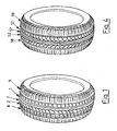
- Fig. 1 shows a high-performance tyre 1 for a motor vehicle.
- Tyre 1 is of the asymmetric type; in other words, it has a pattern which is different (i.e. asymmetric) on each side of an equatorial plane 10 (Fig. 2).
- the structure of the tyre is of the conventional type and comprises a carcass, a tread band located on the crown of said carcass, a pair of axially superimposed sidewalls terminating in beads reinforced with bead wires and corresponding bead fillers, for securing said tyre to a corresponding mounting rim.
- the tyre preferably also comprises a belt structure interposed between the carcass and the tread band. More preferably, the tyre of the of the type with a markedly fattened section, for example in the range from 0.65 to 0.30, where these figures express the percentage value of the ratio between the height of the cross right section of the tyre and the maximum chord of said section. In the art this ratio is usually referred to as H/C.
- the carcass is reinforced with one or more carcass plies fixed to said bead wires, while the belt structure comprises two belt strips, formed from lengths of rubberized fabric incorporating metal cords, parallel to each other in each strip and crossing over those of the adjacent strips, preferably inclined symmetrically with respect to the equatorial plane, and radially superimposed on each other.
- the carcass also comprises a third belt strip, in a radially outermost position, provided with cords, preferably textile and even more preferably made from heat-shrinkable material, orientated circumferentially, i.e. at zero degrees with respect to said equatorial plane.
- Tyre 1 has a tread 2 made from a predetermined compound, provided with deep circumferential grooves 3, 4, 5 and 6. Grooves 3 and 6 divide a central region 7 of the tread from two shoulder regions 8 and 9, located respectively on the left and on the right of equatorial plane 10.
- Central region 7 comprises three circumferential rows of blocks 11, 12 and 13.
- Shoulder region 8 comprises a circumferential row of blocks 14 and shoulder region 9 comprises a circumferential row of blocks 15.
- the row of blocks 14 comprises shoulder blocks 20, of approximately rectangular shape, separated from each other by transverse grooves 21.
- Each block 20 has a sipe 23 which is approximately transverse with respect to equatorial plane 10 and is aligned with a transverse recess 24 towards the outer edge of the tread.
- Blocks 20 are joined at one end by a continuous annular track 22 which terminates in a continuous wall 103 which forms a lateral wall of groove 3.
- Row 11 comprises outer central blocks 26 of an approximately rhomboid shape, separated from each other by transverse grooves 27.
- Blocks 26 are divided into three portions 26a, 26b and 26c. The two portions 26a and 26b are separated by an approximately transverse sipe 28, are axially adjacent to third portion 26c and are separated from the latter by a circumferential recess 29.
- Blocks 26 terminate in walls 30 which form a notched lateral wall 203 of groove 3.
- groove 3 has a width of approximately 10.5 mm and a depth of approximately 8 mm and its lateral walls 103 and 203 are inclined at approximately 5° with respect to a centre-line axis, and are joined by a bottom radius of approximately 4.5 mm.
- the row of blocks 12 is delimited on one side by circumferential groove 4 and is adjacent, on the opposite side, to an annular projection 35, which in turn is delimited by circumferential groove 5.
- Row 12 comprises inner central blocks 36 of approximately semi-parabolic shape, separated from each other by approximately transverse grooves 37, and separated from projection 35 by a circumferential groove 38 which has a half-wave harmonic course.
- the row of blocks 13 is delimited by circumferential groove 6 and is adjacent to an annular projection 40, which, in turn, is delimited by annular groove 5.
- Row 13 comprises outer central blocks 41 of approximately rhomboid shape, separated from each other by transverse grooves 42. Each block 41 is separated from projection 40 by a circumferential recess 43. Blocks 41 terminate in walls 44 which form a notched lateral wall 206 of groove 6.
- the row of blocks 15 comprises shoulder blocks 120, of approximately rectangular shape, separated from each other by transverse grooves 121.
- Each block 120 has an approximately transverse sipe 123, aligned with a transverse recess 124 towards the outer edge of the tread.
- Blocks 120 are joined at one end by a continuous annular track 122 which terminates in a continuous wall 106 which forms a lateral wall of groove 6.
- the two shoulder regions have different widths from each other; for example, the narrower shoulder 8 (on the vehicle side) has a width of approximately 25% of the total width of the tread, while the wider shoulder 9 (preferably on the outer side) has a width of approximately 28% of the total width of the tread.
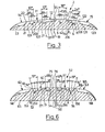
- Continuous lateral wall 106 of groove 6 has a profile, in the radial plane (Fig. 3), which is more inclined with respect to a centre-line axis of the groove, in other words which is more bulky, than the profile of facing lateral wall 206.
- groove 6 has a width of approximately 10.5 mm and a depth of approximately 8 mm
- wall 106 has an inclination of approximately 19° with respect to its centre-line axis and a bottom radius R of approximately 3.5 mm
- wall 206 has an inclination of approximately 5° with respect to the centre-line axis and a bottom radius R1 of approximately 5 mm.
- continuous track 122 imparts optimal rolling to tyre 1, since it prevents the formation, as a result of wear, of "saw tooth” wear deformations on the edges of transverse grooves 121 and of sipes 123, which would give rise to noise and discomfort in travel.
- groove 106 located on the outer edge of the tread, i.e. on the side which is on the exterior of the vehicle when fitted, also makes it possible to improve the wear-resistance of the shoulder of the tyre during severe use in cornering (at high speeds and radii), thus significantly reducing premature wear, particularly of the "saw tooth” wear phenomenon type, on the edges of the circumferential groove. This minimizes the usual degradation of the performance of the tyre due to wear.
- Transverse grooves 27 of the row of blocks 11 have a bottom wall 127 (Fig. 3) which has a cambered profile in a radial plane.
- this profile is of the curvilinear type and extends approximately along an arc whose shape is chosen in such a way as to promote the migration of the compound according, for example, to the viscosity of said compound, which is preferably in the range from 40 ML(1+4) to 110 ML(1+4) (Mooney viscosity), according to information which will be familiar to those skilled, in the art.
- this curvilinear profile has a radius of curvature in the range from 25 to 110 mm.
- Transverse grooves 37 of the row of blocks 12 have a bottom wall 137 with an inclined profile decreasing towards circumferential groove 4.
- this inclined profile has a moderately curvilinear form with a radius of curvature in the range from 90 to 120 mm.
- transverse grooves 42 of the row of blocks 13 have a bottom wall 142 with an inclined profile decreasing towards groove 6.
- said inclined profile has a moderately curvilinear form with a radius of curvature in the range from 90 to 120 mm.
- This configuration with variable depths of the profiles of bottom walls 127, 137 and 142 of transverse grooves 27, 37 and 42 promotes a uniform distribution of the tread compound during vulcanization in an suitable mould, since it facilitates the longitudinal migration of said tread compound along the pitch sequence of the pattern. In this way, non-homogenous and unbalanced distributions of the masses are prevented.
- tread 2 has a width L of approximately 243 mm
- shoulder region 8 has a width of approximately 61.5 mm
- shoulder region 9 has a width of approximately 67.5 mm.
- Each block 120 of row 15 is produced by rotating of 180° a block 20 of row 14 about an axis lying in the plane of the sheet and passing through equatorial plane 10. The block thus produced is then turned over through 180° with respect to an axis lying in the plane of the sheet and perpendicular to equatorial plane 10.
- the pattern of tread 2 has four different pitch values distributed along the extension of the tread according to a predetermined pitch sequence.
- Each pitch represents the length, in a predetermined circumferential direction, of one block and of the adjacent transverse groove; for example, a block 20 or 120 and adjacent groove 21 or 121.
- the pitch sequence is produced according to the invention of US Patent 5,371,685, in order to modulate the noise emitted by the tyre and, in particular, to avoid a siren effect (the presence of resonant phenomena, particularly at high frequency).
- Fig. 4 shows a high-performance tyre 51 for a motor vehicle.
- Tyre 51 is of the directional type; in other words it has a pattern which is symmetrical about an equatorial plane 50 (Fig. 5).
- Tyre 51 has a tread 52 made from a predetermined compound, provided with deep circumferential grooves 53, 54, 55 and 56. Grooves 53 and 56 divide a central region 57 of the tread from two shoulder regions 58 and 59, located respectively on the left and on the right of equatorial plane 50. Circumferential grooves 54 and 55 have a half-wave harmonic course.
- Central region 57 comprises two circumferential rows of blocks 60 and 61.
- Shoulder region 58 has a circumferential row of blocks 62 and shoulder region 59 has a circumferential row of blocks 63.
- the row of blocks 62 comprises shoulder blocks 64, of approximately rectangular shape, separated from each other by transverse grooves 65.
- Each block 64 has an approximately transverse sipe 68 aligned with a transverse recess 69 towards the outer edge.
- Blocks 64 are joined at one end by a continuous annular track 66 which terminates in a continuous wall 153 which forms a lateral wall of groove 53.
- the row of blocks 60 is delimited by circumferential grooves 53 and 54. and comprises central blocks 70 which are approximately cusp-shaped. Blocks 70 are separated from each other by approximately transverse grooves 71 and are divided into two portions 70a and 70b by a curved notch 72. Portion 70a has an approximately transverse sipe 73. Blocks 70 terminate in walls 74 which form a notched wall 253 of groove 53. Transverse grooves 71 have a bottom wall 271 with an inclined profile decreasing towards circumferential groove 53.
- Continuous lateral wall 153 of groove 53 has a profile in a radial plane which is more inclined with respect to a centre-line axis of the groove, in other words which is more bulky, than the profile of facing lateral wall 253.
- groove 53 has a width of approximately 12 mm and a depth of approximately 8 mm, and the wall 153 has an inclination of approximately 14° with respect to a centre-line axis and a bottom radius R of approximately 4.5 mm, while wall 253 has an inclination of approximately 5° with respect to the centre-line axis.
- Central region 57 also comprises two annular projections 75 and 76 located on the left and on the right of equatorial plane 50.
- Projection 75 is delimited by half-wave annular groove 54 and by a circumferential recess 77.
- Projection 76 is delimited by circumferential recess 77 and by half-wave annular groove 55.
- the row of blocks 61 is delimited by circumferential grooves 55 and 56, and comprises central blocks 170 which are mirror images of and out of alignment with blocks 70.
- Blocks 170 are separated from each other by transverse grooves 171 and are divided into two portions 170a and 170b by a thin curved notch 172.
- Portion 170a has an approximately transverse sipe 173.
- Blocks 170 terminate in walls 174 which form a notched wall 256 of groove 56.
- Transverse grooves 171 have a bottom wall 371 with an inclined profile decreasing towards circumferential groove 56.
- the row of blocks 63 comprises shoulder blocks 164 which are mirror images of and out of alignment with blocks 64.
- Shoulder blocks 164 are of approximately rectangular shape and are separated from each other by transverse grooves 165.
- Each block 164 has an approximately transverse sipe 168 aligned with a transverse recess 169 towards the outer edge.
- Blocks 164 are joined at one end by a continuous annular track 166 which terminates in a continuous wall 156 which forms a lateral wall of groove 56.
- Continuous lateral wall 156 of groove 56 has the same profile (identical and a mirror image) and the same dimensions as continuous lateral wall 153 of groove 53.
- tread 52 has a width L of approximately 237 mm and shoulder regions 58 and 59 have each a width of approximately 73 mm.
- Specimens of tyres 1 and 51 were made and were shown to have excellent performance (comfort, quietness, resistance to aquaplaning and to wear) by tests of comparison with conventional tyres conducted both in the laboratory (indoor tests) and on the road and track.
- the tyres according to the invention were compared with the PZero tyre made by the Applicant, which at present is considered to be the reference standard by motor vehicle manufacturers, and with equivalent tyres which represent commercially available alternative types of both asymmetric and directional tyres. Furthermore, the tyre of the present invention has been compared with two commercial tyres selected among the most sold ones. The first was an asymmetric tyre referred to hereinafter as C 1 and the second was a directional tyre referred to hereinafter as C 2 .
- the vehicle used for the tests was a Porsche Carrera 996 fitted, depending on the type of test to be conducted, with four asymmetric tyres or, alternatively, with directional tyres on the front wheels and asymmetric tyres on the rear wheels.
- the tyres fitted on the front wheels were of the 225/40 ZR 18 type, and those fitted on the rear wheels were of the 265/35 ZR 18 type.
- the tyres were fitted on standard rims and were inflated to the nominal operating pressure.
- plastic comfort was evaluated according to the set of sensations perceived by the test driver with respect to the tyre's capacity for absorbing rough areas of the road surface.
- acoustic comfort denotes the noise perceived by the test driver inside the passenger compartment.
- the test consisted in making the tyre, loaded with the nominal operating load, to rotate against a road wheel mounted with a vertical axis of rotation and rotating at a speed in the range from 150 km/h to 0 km/h.
- the road wheel carries on its radially outer surface a bar of parallelepipedal shape of predetermined dimensions which forms the obstacle.
- the tyre is fitted on a fixed dynamometer hub which measures the excitation (force at the hub) that the obstacle produces on the tyre.
- the test yielded the three-dimensional diagrams of the amplitude of the force as a function of speed and frequency. Areas which could be characterized by ranges of speed and frequency were selected from these diagrams and the root mean square value of amplitude (expressed in kg) which forms a parameter predicting the plastic comfort characteristics of the tyre was calculated for each of these areas.
- Directional tyre Root mean square value Invention C 2 Radial 44 50 Longitudinal 51 61
- the range of measurement of the root mean square value in the radial direction of the tyre was from 20 Hz to 40 Hz with a speed decreasing from 120 km/h to 10 km/h.
- the range of measurement of the root mean square value in the longitudinal direction of the tyre was from 60 Hz to 140 Hz with a speed decreasing from 120 km/h to 10 km/h.
- the assessment expressed by the test driver in the evaluation of the plastic comfort improved as the root mean square value, such as that of the tyres according to the invention, decreased.
- the test was conducted on a section of route with smooth and dry asphalt on a bend of constant radius having a predetermined length and having, in a final section, an area of predetermined length covered with a film of water of predetermined thickness.
- Tests were conducted in a chamber acoustically insulated from the exterior (semi-anechoic chamber) with a Porsche car, as specified above, fitted first with new tyres according to the invention and then with new commercial comparison tyres.
- Figures 7 and 8 show the graphs of noise inside the vehicle (dB(A)) as a function of the decreasing speed from 180 to 20 km/h, for a front left-hand tyre and a rear left-hand tyre respectively. More particularly, the curve A relates to the commercial comparison tyre and the curve B relates to the tyre according to the invention.
- the data confirm that the tyre according to the invention, in spite of degradation, maintains a noise level equal to the threshold of acceptability of new tyres, even after 10,800 km of use.
- the measurements of tread wear were carried out at the same time as the noise tests and the results are shown in the attached graphs (Fig. 9) which represent the profile of the blocks, along an axial sequence of meridian planes, reconstructed by a laser beam.
- the measurements shown in Fig. 9 were made after 10,800 km of use of the 225/40 ZR 18 tyre.
- the first two profiles relate to the blocks of the righthand shoulder
- the profiles of the third to the sixth relate to the blocks of the central rows
- the last two profiles relate to the blocks of the left-hand shoulder.
- Each graph shows a portion of the circumferential extension of the tyre where it will be noted that the decrease of the height of the blocks due to wear takes place in a practically uniform way on the periphery of each block and in all of the blocks.
Landscapes
- Engineering & Computer Science (AREA)
- Mechanical Engineering (AREA)
- Tires In General (AREA)
- Transition And Organic Metals Composition Catalysts For Addition Polymerization (AREA)
- Pyridine Compounds (AREA)
- Arrangement Or Mounting Of Propulsion Units For Vehicles (AREA)
- Lubricants (AREA)
Claims (10)
- Pneu à haute performance (1, 51) pour un véhicule automobile comprenant une bande de roulement (2, 52) ayant une largeur totale L et comprenant deux rainures circonférentielles profondes (3, 6, 53, 56), qui séparent une région centrale (7, 57) de deux régions d'épaulement latérales (8, 9, 58, 59), lesdites régions d'épaulement comprenant des pavés d'épaulement (20, 120, 64, 164), la somme des largeurs desdites régions d'épaulement latérales étant inférieure ou égale à 60 % de ladite largeur totale L, la largeur de chacune desdites régions d'épaulement étant supérieure à 20 % de ladite largeur totale L, chacune desdites rainures circonférentielles étant adjacente, au niveau du côté éloigné de ladite région centrale, à une piste continue (22, 122, 66, 166) à partir de laquelle partent des rainures transversales (21, 121, 65, 165) qui délimitent lesdits pavés d'épaulement, ladite piste continue se terminant par une paroi continue (103, 106, 153, 156) qui forme une paroi latérale de ladite rainure circonférentielle, caractérisé en ce que ladite paroi latérale continue d'au moins une rainure circonférentielle a un profil, dans un plan radial, qui est plus incliné, par rapport à un axe médian de ladite rainure circonférentielle, que le profil de la paroi latérale (203, 206, 253, 256) en regard de ladite rainure circonférentielle, et en ce que des pavés (26, 36, 41, 70, 170) de rangées centrales (11, 12, 13, 60, 61) sont séparés par des rainures transversales (27, 37, 42, 71, 171) ayant une paroi de fond (127, 137, 142, 271, 371) qui présente un profil de profondeur variable.
- Pneu selon la revendication 1, caractérisé en ce que ladite paroi latérale continu de ladite rainure circonférentielle présente une inclinaison comprise dans un intervalle allant d'environ 14° à 24° par rapport audit axe médian et un rayon de fond R compris dans un intervalle allant d'environ 2 mm à 5 mm, ladite paroi latérale en regard présentant une inclinaison comprise dans un intervalle allant d'environ 3° à 10° par rapport audit axe médian et un rayon de fond R1 compris dans un intervalle allant d'environ 4 mm à 7 mm.
- Pneu selon la revendication 2, caractérisé en ce que ladite paroi latérale continue de ladite rainure circonférentielle présente une inclinaison d'environ 19° par rapport audit axe médian et un rayon de fond R d'environ 3,5 mm, ladite paroi latérale en regard présentant une inclinaison d'environ 5° par rapport audit axe médian et un rayon de fond R1 d'environ 5 mm.
- Pneu selon la revendication 1, caractérisé en ce qu'au moins un desdits pavés d'épaulement a une lamelle qui est approximativement transversale par rapport à un plan équatorial.
- Pneu selon la revendication 1, caractérisé en ce que ladite région centrale comprend au moins une première et une deuxième rangée circonférentielle de pavés centraux, délimitées par l'une desdites rainures circonférentielles et par une autre rainure circonférentielle profonde.
- Pneu selon la revendication 5, caractérisé en ce que lesdits pavés centraux ont une forme approximativement rhomboïdal.
- Pneu selon la revendication 5, caractérisé en ce que lesdits pavés centraux ont une forme approximativement en corne.
- Pneu selon les revendications 1 à 5, caractérisé en ce que ladite région centrale comprend également une troisième rainure circonférentielle de pavés centraux internes, adjacente à une première saillie annulaire, ladite troisième rainure des blocs et ladite saillie étant délimitées par lesdites autres rainures circonférentielles.
- Pneu selon la revendication 8, caractérisé en ce que lesdits pavés centraux ont approximativement un profil semi-parabolique.
- Pneu à haute performance (1, 51) pour un véhicule automobile comprenant une bande de roulement (2, 52) ayant une région centrale (7, 57) et deux régions d'épaulement latérales (8, 9, 58, 59), la région centrale étant séparée de chaque région d'épaulement par une rainure circonférentielle profonde (3, 6, 53, 56), chaque région d'épaulement comprenant des pavés d'épaulement (20, 120, 64, 164) séparés par des premières rainures transversales, lesdits pavés d'épaulement étant reliés à une extrémité par une piste continue (22, 122, 66, 166) qui se termine par une paroi continue qui forme une paroi latérale (103, 106, 153, 156) de ladite rainure circonférentielle, caractéisé en ce que ladite paroi latérale continue d'au moins une rainure circonférentielle a un profil dans un plan radial qui est plus incliné, par rapport à un axe médian de ladite rainure circonférentielle, que le profil de l'autre face latérale (203, 206, 253, 256) en regard de ladite rainure circonférentielle, et en ce que des pavés (26, 36, 41, 70, 170) de rainures centrales (11, 12, 13, 60, 61) sont séparés par des rainures transversales (27, 37, 42, 71, 171) ayant une paroi de fond (127, 137, 142, 271, 371) qui présente un profil de profondeur variable.
Applications Claiming Priority (5)
| Application Number | Priority Date | Filing Date | Title |
|---|---|---|---|
| ITMI991447 | 1999-06-30 | ||
| IT1999MI001447A ITMI991447A1 (it) | 1999-06-30 | 1999-06-30 | Pneumatico ad alte prestazioni per un autoveicolo |
| US15514299P | 1999-09-22 | 1999-09-22 | |
| US155142P | 1999-09-22 | ||
| PCT/EP2000/005994 WO2001002194A1 (fr) | 1999-06-30 | 2000-06-28 | Pneumatique haute performance pour un vehicule automobile |
Publications (2)
| Publication Number | Publication Date |
|---|---|
| EP1189770A1 EP1189770A1 (fr) | 2002-03-27 |
| EP1189770B1 true EP1189770B1 (fr) | 2004-01-14 |
Family
ID=26331666
Family Applications (1)
| Application Number | Title | Priority Date | Filing Date |
|---|---|---|---|
| EP00945837A Expired - Lifetime EP1189770B1 (fr) | 1999-06-30 | 2000-06-28 | Pneumatique haute performance pour un vehicule automobile |
Country Status (9)
| Country | Link |
|---|---|
| US (1) | US7163039B2 (fr) |
| EP (1) | EP1189770B1 (fr) |
| AT (1) | ATE257775T1 (fr) |
| AU (1) | AU5979200A (fr) |
| DE (1) | DE60007744T2 (fr) |
| ES (1) | ES2213588T3 (fr) |
| PT (1) | PT1189770E (fr) |
| TR (1) | TR200103814T2 (fr) |
| WO (1) | WO2001002194A1 (fr) |
Cited By (3)
| Publication number | Priority date | Publication date | Assignee | Title |
|---|---|---|---|---|
| CN100491142C (zh) * | 2003-07-04 | 2009-05-27 | 倍耐力轮胎公司 | 充气轮胎对、摩托车及改善摩托车在潮湿和干路面上性能的方法 |
| US8622104B2 (en) | 2004-07-16 | 2014-01-07 | Pirelli Tyre S.P.A. | High-performance type for a motor vehicle |
| US9873290B2 (en) | 2004-07-16 | 2018-01-23 | Pirelli Tyre S.P.A. | High-performance tyre for a motor vehicle |
Families Citing this family (37)
| Publication number | Priority date | Publication date | Assignee | Title |
|---|---|---|---|---|
| JP4410453B2 (ja) * | 2002-03-28 | 2010-02-03 | 住友ゴム工業株式会社 | 空気入りタイヤ |
| WO2004024471A1 (fr) * | 2002-08-30 | 2004-03-25 | Bridgestone Corporation | Pneu a structure asymetrique de sculptures et procede de montage du pneu |
| EP1552966B1 (fr) * | 2002-08-30 | 2012-02-22 | Bridgestone Corporation | Pneu et ensemble roue et pneu |
| DE20216992U1 (de) | 2002-11-04 | 2003-01-16 | Goodyear Dunlop Tires Germany GmbH, 63450 Hanau | Fahrzeugluftreifen, insbesondere Sommerreifen für Personenkraftwagen |
| USD501179S1 (en) * | 2003-06-05 | 2005-01-25 | The Yokohama Lubber Co., Ltd. | Automobile tire tread |
| CA105990S (en) * | 2003-09-11 | 2005-07-26 | Yokohama Rubber Co Ltd | Automobile tire |
| JP4274317B2 (ja) * | 2003-10-15 | 2009-06-03 | 横浜ゴム株式会社 | 空気入りタイヤ |
| JP4369734B2 (ja) * | 2003-12-09 | 2009-11-25 | 住友ゴム工業株式会社 | 空気入りタイヤ |
| US20050278308A1 (en) * | 2004-06-01 | 2005-12-15 | Barstow James F | Methods and systems for data integration |
| JP4359262B2 (ja) * | 2005-05-13 | 2009-11-04 | 住友ゴム工業株式会社 | 空気入りタイヤ |
| JP4214159B2 (ja) * | 2006-06-29 | 2009-01-28 | 住友ゴム工業株式会社 | 空気入りタイヤ |
| JP4217267B1 (ja) * | 2007-09-13 | 2009-01-28 | 住友ゴム工業株式会社 | 空気入りタイヤ |
| JP4145346B1 (ja) * | 2007-11-07 | 2008-09-03 | 横浜ゴム株式会社 | 空気入りタイヤ |
| USD598364S1 (en) * | 2008-05-30 | 2009-08-18 | The Yokohama Rubber Co., Ltd | Automobile tire tread |
| JP4367667B1 (ja) * | 2008-06-04 | 2009-11-18 | 横浜ゴム株式会社 | 空気入りタイヤ |
| JP4466765B2 (ja) * | 2008-06-04 | 2010-05-26 | 横浜ゴム株式会社 | 空気入りタイヤ |
| JP5131248B2 (ja) * | 2008-08-05 | 2013-01-30 | 横浜ゴム株式会社 | 空気入りタイヤ |
| JP4653831B2 (ja) * | 2008-10-28 | 2011-03-16 | 住友ゴム工業株式会社 | 空気入りタイヤ |
| CN102232025B (zh) * | 2008-12-10 | 2015-11-25 | 倍耐力轮胎股份公司 | 充气轮胎 |
| CN102427955B (zh) * | 2009-05-19 | 2015-04-01 | 倍耐力轮胎股份公司 | 用于机动车辆的轮胎 |
| CN102803635B (zh) * | 2010-03-19 | 2015-02-18 | 丰田自动车株式会社 | 轮胎的平点的抑制方法及装置 |
| JP5177180B2 (ja) * | 2010-06-18 | 2013-04-03 | 横浜ゴム株式会社 | 空気入りタイヤ |
| JP5140146B2 (ja) * | 2010-12-09 | 2013-02-06 | 住友ゴム工業株式会社 | 空気入りタイヤ |
| ITTO20110471A1 (it) * | 2011-05-30 | 2012-12-01 | Bridgestone Corp | Metodo per determinare il passo longitudinale dei blocchi di una striscia di battistrada |
| JP5385968B2 (ja) * | 2011-12-28 | 2014-01-08 | 住友ゴム工業株式会社 | 空気入りタイヤ |
| JP5647646B2 (ja) * | 2012-06-08 | 2015-01-07 | 住友ゴム工業株式会社 | タイヤの加硫金型及び空気入りタイヤの製造方法 |
| JP5912945B2 (ja) * | 2012-07-10 | 2016-04-27 | 住友ゴム工業株式会社 | 空気入りタイヤ |
| US10252577B2 (en) * | 2012-11-15 | 2019-04-09 | The Yokohama Rubber Co., Ltd. | Pneumatic tire |
| US9033011B1 (en) * | 2013-12-09 | 2015-05-19 | The Goodyear Tire & Rubber Company | Tire comprising a tread with asymmetric groove profiles |
| US11203234B2 (en) * | 2014-08-12 | 2021-12-21 | The Yokohama Rubber Co., Ltd. | Pneumatic tire |
| US10363781B2 (en) | 2015-10-26 | 2019-07-30 | Sumitomo Rubber Industries, Ltd. | Tire |
| CN109515069B (zh) * | 2017-09-19 | 2022-04-26 | 住友橡胶工业株式会社 | 轮胎 |
| US11135877B2 (en) | 2017-09-19 | 2021-10-05 | Sumitomo Rubber Industries, Ltd. | Tire |
| CN110362088B (zh) * | 2019-08-02 | 2022-07-12 | 上海振华重工(集团)股份有限公司 | 一种适用于无人驾驶跨运车的循迹控制系统和方法 |
| IT202000016684A1 (it) | 2020-07-09 | 2022-01-09 | Pirelli | Pneumatico per autovetture |
| US20220055410A1 (en) * | 2020-08-21 | 2022-02-24 | The Goodyear Tire & Rubber Company | Tire tread with asymmetric shoulder groove |
| FR3161386A1 (fr) * | 2024-04-18 | 2025-10-24 | Compagnie Generale Des Etablissements Michelin | Pneumatique à bonne adhérence sur sol mouillé et à grande longévité |
Family Cites Families (28)
| Publication number | Priority date | Publication date | Assignee | Title |
|---|---|---|---|---|
| NL133931C (fr) * | 1966-12-19 | |||
| FR1528052A (fr) * | 1967-04-27 | 1968-06-07 | Michelin & Cie | Perfectionnements aux enveloppes de pneumatiques |
| US4299264A (en) * | 1979-04-12 | 1981-11-10 | Dunlop Limited | Tires |
| US4446901A (en) * | 1981-05-13 | 1984-05-08 | Bridgestone Tire Company Limited | Heavy duty pneumatic radial tires |
| JPS6064004A (ja) * | 1983-09-20 | 1985-04-12 | Bridgestone Corp | 接地性にすぐれた不整地走行用タイヤ |
| JPS60193704A (ja) * | 1984-03-15 | 1985-10-02 | Sumitomo Rubber Ind Ltd | 空気入りタイヤ |
| JPS6116109A (ja) * | 1984-06-30 | 1986-01-24 | Sumitomo Rubber Ind Ltd | トラック、バス用タイヤ |
| JPS62286804A (ja) * | 1986-06-04 | 1987-12-12 | Bridgestone Corp | 偏平空気入りタイヤ |
| JPS6361606A (ja) | 1986-08-30 | 1988-03-17 | Bridgestone Corp | 空気入りラジアルタイヤ |
| JPS63162308A (ja) * | 1986-12-26 | 1988-07-05 | Bridgestone Corp | 高速走行に供せられる偏平空気入りラジアルタイヤ |
| JPH0536963Y2 (fr) * | 1987-08-27 | 1993-09-20 | ||
| JPH01266001A (ja) * | 1988-04-19 | 1989-10-24 | Yokohama Rubber Co Ltd:The | 空気入りタイヤ |
| EP0357462A3 (fr) * | 1988-09-02 | 1990-12-05 | Bridgestone Corporation | Bandages pneumatiques |
| IT1237958B (it) * | 1990-01-17 | 1993-06-19 | Pirelli | Sequenze di elementi di battistrada di pneumatici di veicoli a bassa rumorisita' e relativo metodo di generazione |
| JP2973022B2 (ja) * | 1990-10-05 | 1999-11-08 | 横浜ゴム株式会社 | 空気入りラジアルタイヤ |
| CA2058813A1 (fr) * | 1991-07-26 | 1993-01-27 | Warren Lee Croyle | Semelle de roulement pour pneu |
| JPH06106916A (ja) * | 1992-09-30 | 1994-04-19 | Bridgestone Corp | 空気入りタイヤ |
| AT400553B (de) * | 1993-02-16 | 1996-01-25 | Semperit Ag | Fahrzeugluftreifen |
| IT1265035B1 (it) * | 1993-05-31 | 1996-10-28 | Pirelli | Pneumatico per ruote di veicoli con battistrada a bassa rumorosita' di rotolamento |
| JPH0811508A (ja) | 1994-06-30 | 1996-01-16 | Bridgestone Corp | 空気入りタイヤ |
| JP3488756B2 (ja) * | 1995-01-25 | 2004-01-19 | 横浜ゴム株式会社 | 空気入りタイヤ |
| US5746849A (en) * | 1995-12-11 | 1998-05-05 | The Goodyear Tire & Rubber Company | Tire tread including tie bar |
| JP3113592B2 (ja) * | 1996-02-15 | 2000-12-04 | 住友ゴム工業株式会社 | 空気入りラジアルタイヤ |
| JP3718021B2 (ja) * | 1997-02-21 | 2005-11-16 | 株式会社ブリヂストン | オール・シーズン乗用車用空気入りラジアル・タイヤ |
| JPH111105A (ja) * | 1997-06-13 | 1999-01-06 | Bridgestone Corp | 空気入りタイヤ |
| JPH1191314A (ja) * | 1997-09-26 | 1999-04-06 | Bridgestone Corp | 排水性能に優れた乗用車用空気入りタイヤ |
| JP4272301B2 (ja) * | 1998-06-18 | 2009-06-03 | 住友ゴム工業株式会社 | トレッドパタ−ン形成方法 |
| USD490047S1 (en) * | 2003-09-11 | 2004-05-18 | The Goodyear Tire & Rubber Company | Tire tread |
-
2000
- 2000-06-28 EP EP00945837A patent/EP1189770B1/fr not_active Expired - Lifetime
- 2000-06-28 PT PT00945837T patent/PT1189770E/pt unknown
- 2000-06-28 DE DE60007744T patent/DE60007744T2/de not_active Expired - Lifetime
- 2000-06-28 AT AT00945837T patent/ATE257775T1/de not_active IP Right Cessation
- 2000-06-28 WO PCT/EP2000/005994 patent/WO2001002194A1/fr not_active Ceased
- 2000-06-28 AU AU59792/00A patent/AU5979200A/en not_active Abandoned
- 2000-06-28 ES ES00945837T patent/ES2213588T3/es not_active Expired - Lifetime
- 2000-06-28 TR TR2001/03814T patent/TR200103814T2/xx unknown
-
2001
- 2001-12-28 US US10/029,174 patent/US7163039B2/en not_active Expired - Lifetime
Cited By (3)
| Publication number | Priority date | Publication date | Assignee | Title |
|---|---|---|---|---|
| CN100491142C (zh) * | 2003-07-04 | 2009-05-27 | 倍耐力轮胎公司 | 充气轮胎对、摩托车及改善摩托车在潮湿和干路面上性能的方法 |
| US8622104B2 (en) | 2004-07-16 | 2014-01-07 | Pirelli Tyre S.P.A. | High-performance type for a motor vehicle |
| US9873290B2 (en) | 2004-07-16 | 2018-01-23 | Pirelli Tyre S.P.A. | High-performance tyre for a motor vehicle |
Also Published As
| Publication number | Publication date |
|---|---|
| US20020139460A1 (en) | 2002-10-03 |
| AU5979200A (en) | 2001-01-22 |
| WO2001002194A1 (fr) | 2001-01-11 |
| DE60007744D1 (de) | 2004-02-19 |
| ATE257775T1 (de) | 2004-01-15 |
| TR200103814T2 (tr) | 2002-06-21 |
| DE60007744T2 (de) | 2004-12-09 |
| PT1189770E (pt) | 2004-06-30 |
| US7163039B2 (en) | 2007-01-16 |
| ES2213588T3 (es) | 2004-09-01 |
| EP1189770A1 (fr) | 2002-03-27 |
Similar Documents
| Publication | Publication Date | Title |
|---|---|---|
| US7163039B2 (en) | High-performance tire for a motor vehicle | |
| JP3515232B2 (ja) | 空気入りタイヤ及びその使用方法 | |
| EP2373497B1 (fr) | Pneu | |
| JP3367927B2 (ja) | 空気入りタイヤ | |
| US8210219B2 (en) | Pneumatic tire with tread having crown rib and middle ribs | |
| EP0508090B1 (fr) | Bandage pneumatique ayant une surface de contact au sol particulière | |
| US5658404A (en) | Radial pneumatic light truck or automobile tire | |
| AU2006201886B2 (en) | Pneumatic tire | |
| JP2966760B2 (ja) | 重荷重用タイヤ | |
| CN110722934B (zh) | 车辆轮胎 | |
| EP0688685B1 (fr) | Bandage pneumatique | |
| EP0904960B1 (fr) | Bandage pneumatique sans crampons | |
| AU2017216718B2 (en) | Pneumatic tire | |
| EP0680837B1 (fr) | Bandage pneumatique | |
| JP4979864B2 (ja) | 自動車用高性能タイヤ | |
| EP0870630B1 (fr) | Bandage pneumatique | |
| WO2019159564A1 (fr) | Pneumatique | |
| EP0916523B1 (fr) | Bandage pneumatique | |
| JP3961855B2 (ja) | 空気入りタイヤ | |
| JP2023150618A (ja) | タイヤ | |
| US20240010031A1 (en) | Pneumatic tire | |
| EP0678403B1 (fr) | Bandage pneumatique | |
| JP7575662B2 (ja) | タイヤ | |
| JP6919666B2 (ja) | 空気入りタイヤ | |
| JP3262871B2 (ja) | 空気入りラジアルタイヤ |
Legal Events
| Date | Code | Title | Description |
|---|---|---|---|
| PUAI | Public reference made under article 153(3) epc to a published international application that has entered the european phase |
Free format text: ORIGINAL CODE: 0009012 |
|
| 17P | Request for examination filed |
Effective date: 20011217 |
|
| AK | Designated contracting states |
Kind code of ref document: A1 Designated state(s): AT BE CH CY DE DK ES FI FR GB GR IE IT LI LU MC NL PT SE |
|
| AX | Request for extension of the european patent |
Free format text: AL;LT;LV;MK;RO;SI |
|
| GRAP | Despatch of communication of intention to grant a patent |
Free format text: ORIGINAL CODE: EPIDOSNIGR1 |
|
| GRAS | Grant fee paid |
Free format text: ORIGINAL CODE: EPIDOSNIGR3 |
|
| GRAA | (expected) grant |
Free format text: ORIGINAL CODE: 0009210 |
|
| AK | Designated contracting states |
Kind code of ref document: B1 Designated state(s): AT BE CH CY DE DK ES FI FR GB GR IE IT LI LU MC NL PT SE |
|
| PG25 | Lapsed in a contracting state [announced via postgrant information from national office to epo] |
Ref country code: CY Free format text: LAPSE BECAUSE OF FAILURE TO SUBMIT A TRANSLATION OF THE DESCRIPTION OR TO PAY THE FEE WITHIN THE PRESCRIBED TIME-LIMIT Effective date: 20040114 Ref country code: FI Free format text: LAPSE BECAUSE OF FAILURE TO SUBMIT A TRANSLATION OF THE DESCRIPTION OR TO PAY THE FEE WITHIN THE PRESCRIBED TIME-LIMIT Effective date: 20040114 |
|
| REG | Reference to a national code |
Ref country code: GB Ref legal event code: FG4D |
|
| REG | Reference to a national code |
Ref country code: CH Ref legal event code: EP |
|
| REG | Reference to a national code |
Ref country code: IE Ref legal event code: FG4D |
|
| REF | Corresponds to: |
Ref document number: 60007744 Country of ref document: DE Date of ref document: 20040219 Kind code of ref document: P |
|
| PG25 | Lapsed in a contracting state [announced via postgrant information from national office to epo] |
Ref country code: DK Free format text: LAPSE BECAUSE OF FAILURE TO SUBMIT A TRANSLATION OF THE DESCRIPTION OR TO PAY THE FEE WITHIN THE PRESCRIBED TIME-LIMIT Effective date: 20040414 Ref country code: GR Free format text: LAPSE BECAUSE OF FAILURE TO SUBMIT A TRANSLATION OF THE DESCRIPTION OR TO PAY THE FEE WITHIN THE PRESCRIBED TIME-LIMIT Effective date: 20040414 |
|
| REG | Reference to a national code |
Ref country code: SE Ref legal event code: TRGR |
|
| REG | Reference to a national code |
Ref country code: CH Ref legal event code: NV Representative=s name: FIAMMENGHI-FIAMMENGHI |
|
| LTIE | Lt: invalidation of european patent or patent extension |
Effective date: 20040114 |
|
| PG25 | Lapsed in a contracting state [announced via postgrant information from national office to epo] |
Ref country code: LU Free format text: LAPSE BECAUSE OF NON-PAYMENT OF DUE FEES Effective date: 20040628 Ref country code: IE Free format text: LAPSE BECAUSE OF NON-PAYMENT OF DUE FEES Effective date: 20040628 |
|
| PG25 | Lapsed in a contracting state [announced via postgrant information from national office to epo] |
Ref country code: MC Free format text: LAPSE BECAUSE OF NON-PAYMENT OF DUE FEES Effective date: 20040630 |
|
| REG | Reference to a national code |
Ref country code: PT Ref legal event code: SC4A Free format text: AVAILABILITY OF NATIONAL TRANSLATION Effective date: 20040412 |
|
| REG | Reference to a national code |
Ref country code: ES Ref legal event code: FG2A Ref document number: 2213588 Country of ref document: ES Kind code of ref document: T3 |
|
| ET | Fr: translation filed | ||
| PLBE | No opposition filed within time limit |
Free format text: ORIGINAL CODE: 0009261 |
|
| STAA | Information on the status of an ep patent application or granted ep patent |
Free format text: STATUS: NO OPPOSITION FILED WITHIN TIME LIMIT |
|
| 26N | No opposition filed |
Effective date: 20041015 |
|
| REG | Reference to a national code |
Ref country code: IE Ref legal event code: MM4A |
|
| PGFP | Annual fee paid to national office [announced via postgrant information from national office to epo] |
Ref country code: CH Payment date: 20080630 Year of fee payment: 9 Ref country code: ES Payment date: 20080626 Year of fee payment: 9 |
|
| PGFP | Annual fee paid to national office [announced via postgrant information from national office to epo] |
Ref country code: AT Payment date: 20080603 Year of fee payment: 9 |
|
| PGFP | Annual fee paid to national office [announced via postgrant information from national office to epo] |
Ref country code: PT Payment date: 20080605 Year of fee payment: 9 |
|
| PGFP | Annual fee paid to national office [announced via postgrant information from national office to epo] |
Ref country code: BE Payment date: 20080730 Year of fee payment: 9 Ref country code: SE Payment date: 20080627 Year of fee payment: 9 |
|
| BERE | Be: lapsed |
Owner name: *PIRELLI PNEUMATICI S.P.A. Effective date: 20090630 |
|
| REG | Reference to a national code |
Ref country code: PT Ref legal event code: MM4A Free format text: LAPSE DUE TO NON-PAYMENT OF FEES Effective date: 20091228 |
|
| REG | Reference to a national code |
Ref country code: CH Ref legal event code: PL |
|
| PG25 | Lapsed in a contracting state [announced via postgrant information from national office to epo] |
Ref country code: PT Free format text: LAPSE BECAUSE OF NON-PAYMENT OF DUE FEES Effective date: 20091228 |
|
| PG25 | Lapsed in a contracting state [announced via postgrant information from national office to epo] |
Ref country code: CH Free format text: LAPSE BECAUSE OF NON-PAYMENT OF DUE FEES Effective date: 20090630 Ref country code: LI Free format text: LAPSE BECAUSE OF NON-PAYMENT OF DUE FEES Effective date: 20090630 |
|
| PG25 | Lapsed in a contracting state [announced via postgrant information from national office to epo] |
Ref country code: AT Free format text: LAPSE BECAUSE OF NON-PAYMENT OF DUE FEES Effective date: 20090628 Ref country code: BE Free format text: LAPSE BECAUSE OF NON-PAYMENT OF DUE FEES Effective date: 20090630 |
|
| REG | Reference to a national code |
Ref country code: ES Ref legal event code: FD2A Effective date: 20090629 |
|
| PG25 | Lapsed in a contracting state [announced via postgrant information from national office to epo] |
Ref country code: ES Free format text: LAPSE BECAUSE OF NON-PAYMENT OF DUE FEES Effective date: 20090629 |
|
| PG25 | Lapsed in a contracting state [announced via postgrant information from national office to epo] |
Ref country code: SE Free format text: LAPSE BECAUSE OF NON-PAYMENT OF DUE FEES Effective date: 20090629 |
|
| REG | Reference to a national code |
Ref country code: FR Ref legal event code: PLFP Year of fee payment: 17 |
|
| REG | Reference to a national code |
Ref country code: FR Ref legal event code: PLFP Year of fee payment: 18 |
|
| REG | Reference to a national code |
Ref country code: FR Ref legal event code: PLFP Year of fee payment: 19 |
|
| PGFP | Annual fee paid to national office [announced via postgrant information from national office to epo] |
Ref country code: NL Payment date: 20190626 Year of fee payment: 20 Ref country code: IT Payment date: 20190621 Year of fee payment: 20 |
|
| PGFP | Annual fee paid to national office [announced via postgrant information from national office to epo] |
Ref country code: FR Payment date: 20190625 Year of fee payment: 20 |
|
| PGFP | Annual fee paid to national office [announced via postgrant information from national office to epo] |
Ref country code: DE Payment date: 20190627 Year of fee payment: 20 Ref country code: GB Payment date: 20190627 Year of fee payment: 20 |
|
| REG | Reference to a national code |
Ref country code: DE Ref legal event code: R071 Ref document number: 60007744 Country of ref document: DE |
|
| REG | Reference to a national code |
Ref country code: NL Ref legal event code: MK Effective date: 20200627 |
|
| REG | Reference to a national code |
Ref country code: GB Ref legal event code: PE20 Expiry date: 20200627 |
|
| PG25 | Lapsed in a contracting state [announced via postgrant information from national office to epo] |
Ref country code: GB Free format text: LAPSE BECAUSE OF EXPIRATION OF PROTECTION Effective date: 20200627 |