EP2610470A2 - Procédé de fonctionnement d'une centrale stationnaire avec au moins un moteur à combustion interne - Google Patents
Procédé de fonctionnement d'une centrale stationnaire avec au moins un moteur à combustion interne Download PDFInfo
- Publication number
- EP2610470A2 EP2610470A2 EP12007808.4A EP12007808A EP2610470A2 EP 2610470 A2 EP2610470 A2 EP 2610470A2 EP 12007808 A EP12007808 A EP 12007808A EP 2610470 A2 EP2610470 A2 EP 2610470A2
- Authority
- EP
- European Patent Office
- Prior art keywords
- air
- heat exchanger
- cold air
- internal combustion
- combustion engine
- Prior art date
- Legal status (The legal status is an assumption and is not a legal conclusion. Google has not performed a legal analysis and makes no representation as to the accuracy of the status listed.)
- Withdrawn
Links
Images

Classifications
-
- F—MECHANICAL ENGINEERING; LIGHTING; HEATING; WEAPONS; BLASTING
- F02—COMBUSTION ENGINES; HOT-GAS OR COMBUSTION-PRODUCT ENGINE PLANTS
- F02G—HOT GAS OR COMBUSTION-PRODUCT POSITIVE-DISPLACEMENT ENGINE PLANTS; USE OF WASTE HEAT OF COMBUSTION ENGINES; NOT OTHERWISE PROVIDED FOR
- F02G5/00—Profiting from waste heat of combustion engines, not otherwise provided for
- F02G5/02—Profiting from waste heat of exhaust gases
-
- F—MECHANICAL ENGINEERING; LIGHTING; HEATING; WEAPONS; BLASTING
- F01—MACHINES OR ENGINES IN GENERAL; ENGINE PLANTS IN GENERAL; STEAM ENGINES
- F01K—STEAM ENGINE PLANTS; STEAM ACCUMULATORS; ENGINE PLANTS NOT OTHERWISE PROVIDED FOR; ENGINES USING SPECIAL WORKING FLUIDS OR CYCLES
- F01K23/00—Plants characterised by more than one engine delivering power external to the plant, the engines being driven by different fluids
- F01K23/02—Plants characterised by more than one engine delivering power external to the plant, the engines being driven by different fluids the engine cycles being thermally coupled
- F01K23/06—Plants characterised by more than one engine delivering power external to the plant, the engines being driven by different fluids the engine cycles being thermally coupled combustion heat from one cycle heating the fluid in another cycle
- F01K23/065—Plants characterised by more than one engine delivering power external to the plant, the engines being driven by different fluids the engine cycles being thermally coupled combustion heat from one cycle heating the fluid in another cycle the combustion taking place in an internal combustion piston engine, e.g. a diesel engine
-
- F—MECHANICAL ENGINEERING; LIGHTING; HEATING; WEAPONS; BLASTING
- F01—MACHINES OR ENGINES IN GENERAL; ENGINE PLANTS IN GENERAL; STEAM ENGINES
- F01K—STEAM ENGINE PLANTS; STEAM ACCUMULATORS; ENGINE PLANTS NOT OTHERWISE PROVIDED FOR; ENGINES USING SPECIAL WORKING FLUIDS OR CYCLES
- F01K23/00—Plants characterised by more than one engine delivering power external to the plant, the engines being driven by different fluids
- F01K23/02—Plants characterised by more than one engine delivering power external to the plant, the engines being driven by different fluids the engine cycles being thermally coupled
- F01K23/06—Plants characterised by more than one engine delivering power external to the plant, the engines being driven by different fluids the engine cycles being thermally coupled combustion heat from one cycle heating the fluid in another cycle
- F01K23/10—Plants characterised by more than one engine delivering power external to the plant, the engines being driven by different fluids the engine cycles being thermally coupled combustion heat from one cycle heating the fluid in another cycle with exhaust fluid of one cycle heating the fluid in another cycle
-
- F—MECHANICAL ENGINEERING; LIGHTING; HEATING; WEAPONS; BLASTING
- F01—MACHINES OR ENGINES IN GENERAL; ENGINE PLANTS IN GENERAL; STEAM ENGINES
- F01K—STEAM ENGINE PLANTS; STEAM ACCUMULATORS; ENGINE PLANTS NOT OTHERWISE PROVIDED FOR; ENGINES USING SPECIAL WORKING FLUIDS OR CYCLES
- F01K25/00—Plants or engines characterised by use of special working fluids, not otherwise provided for; Plants operating in closed cycles and not otherwise provided for
- F01K25/08—Plants or engines characterised by use of special working fluids, not otherwise provided for; Plants operating in closed cycles and not otherwise provided for using special vapours
-
- F—MECHANICAL ENGINEERING; LIGHTING; HEATING; WEAPONS; BLASTING
- F01—MACHINES OR ENGINES IN GENERAL; ENGINE PLANTS IN GENERAL; STEAM ENGINES
- F01K—STEAM ENGINE PLANTS; STEAM ACCUMULATORS; ENGINE PLANTS NOT OTHERWISE PROVIDED FOR; ENGINES USING SPECIAL WORKING FLUIDS OR CYCLES
- F01K9/00—Plants characterised by condensers arranged or modified to co-operate with the engines
- F01K9/003—Plants characterised by condensers arranged or modified to co-operate with the engines condenser cooling circuits
-
- F—MECHANICAL ENGINEERING; LIGHTING; HEATING; WEAPONS; BLASTING
- F02—COMBUSTION ENGINES; HOT-GAS OR COMBUSTION-PRODUCT ENGINE PLANTS
- F02G—HOT GAS OR COMBUSTION-PRODUCT POSITIVE-DISPLACEMENT ENGINE PLANTS; USE OF WASTE HEAT OF COMBUSTION ENGINES; NOT OTHERWISE PROVIDED FOR
- F02G5/00—Profiting from waste heat of combustion engines, not otherwise provided for
-
- F—MECHANICAL ENGINEERING; LIGHTING; HEATING; WEAPONS; BLASTING
- F02—COMBUSTION ENGINES; HOT-GAS OR COMBUSTION-PRODUCT ENGINE PLANTS
- F02G—HOT GAS OR COMBUSTION-PRODUCT POSITIVE-DISPLACEMENT ENGINE PLANTS; USE OF WASTE HEAT OF COMBUSTION ENGINES; NOT OTHERWISE PROVIDED FOR
- F02G5/00—Profiting from waste heat of combustion engines, not otherwise provided for
- F02G5/02—Profiting from waste heat of exhaust gases
- F02G5/04—Profiting from waste heat of exhaust gases in combination with other waste heat from combustion engines
-
- F—MECHANICAL ENGINEERING; LIGHTING; HEATING; WEAPONS; BLASTING
- F25—REFRIGERATION OR COOLING; COMBINED HEATING AND REFRIGERATION SYSTEMS; HEAT PUMP SYSTEMS; MANUFACTURE OR STORAGE OF ICE; LIQUEFACTION SOLIDIFICATION OF GASES
- F25J—LIQUEFACTION, SOLIDIFICATION OR SEPARATION OF GASES OR GASEOUS OR LIQUEFIED GASEOUS MIXTURES BY PRESSURE AND COLD TREATMENT OR BY BRINGING THEM INTO THE SUPERCRITICAL STATE
- F25J1/00—Processes or apparatus for liquefying or solidifying gases or gaseous mixtures
- F25J1/0002—Processes or apparatus for liquefying or solidifying gases or gaseous mixtures characterised by the fluid to be liquefied
- F25J1/0012—Primary atmospheric gases, e.g. air
-
- F—MECHANICAL ENGINEERING; LIGHTING; HEATING; WEAPONS; BLASTING
- F25—REFRIGERATION OR COOLING; COMBINED HEATING AND REFRIGERATION SYSTEMS; HEAT PUMP SYSTEMS; MANUFACTURE OR STORAGE OF ICE; LIQUEFACTION SOLIDIFICATION OF GASES
- F25J—LIQUEFACTION, SOLIDIFICATION OR SEPARATION OF GASES OR GASEOUS OR LIQUEFIED GASEOUS MIXTURES BY PRESSURE AND COLD TREATMENT OR BY BRINGING THEM INTO THE SUPERCRITICAL STATE
- F25J1/00—Processes or apparatus for liquefying or solidifying gases or gaseous mixtures
- F25J1/003—Processes or apparatus for liquefying or solidifying gases or gaseous mixtures characterised by the kind of cold generation within the liquefaction unit for compensating heat leaks and liquid production
- F25J1/0032—Processes or apparatus for liquefying or solidifying gases or gaseous mixtures characterised by the kind of cold generation within the liquefaction unit for compensating heat leaks and liquid production using the feed stream itself or separated fractions from it, i.e. "internal refrigeration"
- F25J1/004—Processes or apparatus for liquefying or solidifying gases or gaseous mixtures characterised by the kind of cold generation within the liquefaction unit for compensating heat leaks and liquid production using the feed stream itself or separated fractions from it, i.e. "internal refrigeration" by flash gas recovery
-
- F—MECHANICAL ENGINEERING; LIGHTING; HEATING; WEAPONS; BLASTING
- F25—REFRIGERATION OR COOLING; COMBINED HEATING AND REFRIGERATION SYSTEMS; HEAT PUMP SYSTEMS; MANUFACTURE OR STORAGE OF ICE; LIQUEFACTION SOLIDIFICATION OF GASES
- F25J—LIQUEFACTION, SOLIDIFICATION OR SEPARATION OF GASES OR GASEOUS OR LIQUEFIED GASEOUS MIXTURES BY PRESSURE AND COLD TREATMENT OR BY BRINGING THEM INTO THE SUPERCRITICAL STATE
- F25J1/00—Processes or apparatus for liquefying or solidifying gases or gaseous mixtures
- F25J1/02—Processes or apparatus for liquefying or solidifying gases or gaseous mixtures requiring the use of refrigeration, e.g. of helium or hydrogen ; Details and kind of the refrigeration system used; Integration with other units or processes; Controlling aspects of the process
- F25J1/0201—Processes or apparatus for liquefying or solidifying gases or gaseous mixtures requiring the use of refrigeration, e.g. of helium or hydrogen ; Details and kind of the refrigeration system used; Integration with other units or processes; Controlling aspects of the process using only internal refrigeration means, i.e. without external refrigeration
- F25J1/0202—Processes or apparatus for liquefying or solidifying gases or gaseous mixtures requiring the use of refrigeration, e.g. of helium or hydrogen ; Details and kind of the refrigeration system used; Integration with other units or processes; Controlling aspects of the process using only internal refrigeration means, i.e. without external refrigeration in a quasi-closed internal refrigeration loop
-
- F—MECHANICAL ENGINEERING; LIGHTING; HEATING; WEAPONS; BLASTING
- F25—REFRIGERATION OR COOLING; COMBINED HEATING AND REFRIGERATION SYSTEMS; HEAT PUMP SYSTEMS; MANUFACTURE OR STORAGE OF ICE; LIQUEFACTION SOLIDIFICATION OF GASES
- F25J—LIQUEFACTION, SOLIDIFICATION OR SEPARATION OF GASES OR GASEOUS OR LIQUEFIED GASEOUS MIXTURES BY PRESSURE AND COLD TREATMENT OR BY BRINGING THEM INTO THE SUPERCRITICAL STATE
- F25J1/00—Processes or apparatus for liquefying or solidifying gases or gaseous mixtures
- F25J1/02—Processes or apparatus for liquefying or solidifying gases or gaseous mixtures requiring the use of refrigeration, e.g. of helium or hydrogen ; Details and kind of the refrigeration system used; Integration with other units or processes; Controlling aspects of the process
- F25J1/0228—Coupling of the liquefaction unit to other units or processes, so-called integrated processes
- F25J1/0235—Heat exchange integration
- F25J1/0242—Waste heat recovery, e.g. from heat of compression
-
- F—MECHANICAL ENGINEERING; LIGHTING; HEATING; WEAPONS; BLASTING
- F25—REFRIGERATION OR COOLING; COMBINED HEATING AND REFRIGERATION SYSTEMS; HEAT PUMP SYSTEMS; MANUFACTURE OR STORAGE OF ICE; LIQUEFACTION SOLIDIFICATION OF GASES
- F25J—LIQUEFACTION, SOLIDIFICATION OR SEPARATION OF GASES OR GASEOUS OR LIQUEFIED GASEOUS MIXTURES BY PRESSURE AND COLD TREATMENT OR BY BRINGING THEM INTO THE SUPERCRITICAL STATE
- F25J1/00—Processes or apparatus for liquefying or solidifying gases or gaseous mixtures
- F25J1/02—Processes or apparatus for liquefying or solidifying gases or gaseous mixtures requiring the use of refrigeration, e.g. of helium or hydrogen ; Details and kind of the refrigeration system used; Integration with other units or processes; Controlling aspects of the process
- F25J1/0243—Start-up or control of the process; Details of the apparatus used; Details of the refrigerant compression system used
- F25J1/0244—Operation; Control and regulation; Instrumentation
- F25J1/0245—Different modes, i.e. 'runs', of operation; Process control
- F25J1/0251—Intermittent or alternating process, so-called batch process, e.g. "peak-shaving"
-
- F—MECHANICAL ENGINEERING; LIGHTING; HEATING; WEAPONS; BLASTING
- F25—REFRIGERATION OR COOLING; COMBINED HEATING AND REFRIGERATION SYSTEMS; HEAT PUMP SYSTEMS; MANUFACTURE OR STORAGE OF ICE; LIQUEFACTION SOLIDIFICATION OF GASES
- F25J—LIQUEFACTION, SOLIDIFICATION OR SEPARATION OF GASES OR GASEOUS OR LIQUEFIED GASEOUS MIXTURES BY PRESSURE AND COLD TREATMENT OR BY BRINGING THEM INTO THE SUPERCRITICAL STATE
- F25J1/00—Processes or apparatus for liquefying or solidifying gases or gaseous mixtures
- F25J1/02—Processes or apparatus for liquefying or solidifying gases or gaseous mixtures requiring the use of refrigeration, e.g. of helium or hydrogen ; Details and kind of the refrigeration system used; Integration with other units or processes; Controlling aspects of the process
- F25J1/0243—Start-up or control of the process; Details of the apparatus used; Details of the refrigerant compression system used
- F25J1/0244—Operation; Control and regulation; Instrumentation
- F25J1/0254—Operation; Control and regulation; Instrumentation controlling particular process parameter, e.g. pressure, temperature
-
- F—MECHANICAL ENGINEERING; LIGHTING; HEATING; WEAPONS; BLASTING
- F25—REFRIGERATION OR COOLING; COMBINED HEATING AND REFRIGERATION SYSTEMS; HEAT PUMP SYSTEMS; MANUFACTURE OR STORAGE OF ICE; LIQUEFACTION SOLIDIFICATION OF GASES
- F25J—LIQUEFACTION, SOLIDIFICATION OR SEPARATION OF GASES OR GASEOUS OR LIQUEFIED GASEOUS MIXTURES BY PRESSURE AND COLD TREATMENT OR BY BRINGING THEM INTO THE SUPERCRITICAL STATE
- F25J1/00—Processes or apparatus for liquefying or solidifying gases or gaseous mixtures
- F25J1/02—Processes or apparatus for liquefying or solidifying gases or gaseous mixtures requiring the use of refrigeration, e.g. of helium or hydrogen ; Details and kind of the refrigeration system used; Integration with other units or processes; Controlling aspects of the process
- F25J1/0243—Start-up or control of the process; Details of the apparatus used; Details of the refrigerant compression system used
- F25J1/0279—Compression of refrigerant or internal recycle fluid, e.g. kind of compressor, accumulator, suction drum etc.
-
- F—MECHANICAL ENGINEERING; LIGHTING; HEATING; WEAPONS; BLASTING
- F25—REFRIGERATION OR COOLING; COMBINED HEATING AND REFRIGERATION SYSTEMS; HEAT PUMP SYSTEMS; MANUFACTURE OR STORAGE OF ICE; LIQUEFACTION SOLIDIFICATION OF GASES
- F25J—LIQUEFACTION, SOLIDIFICATION OR SEPARATION OF GASES OR GASEOUS OR LIQUEFIED GASEOUS MIXTURES BY PRESSURE AND COLD TREATMENT OR BY BRINGING THEM INTO THE SUPERCRITICAL STATE
- F25J1/00—Processes or apparatus for liquefying or solidifying gases or gaseous mixtures
- F25J1/02—Processes or apparatus for liquefying or solidifying gases or gaseous mixtures requiring the use of refrigeration, e.g. of helium or hydrogen ; Details and kind of the refrigeration system used; Integration with other units or processes; Controlling aspects of the process
- F25J1/0243—Start-up or control of the process; Details of the apparatus used; Details of the refrigerant compression system used
- F25J1/0279—Compression of refrigerant or internal recycle fluid, e.g. kind of compressor, accumulator, suction drum etc.
- F25J1/0296—Removal of the heat of compression, e.g. within an inter- or afterstage-cooler against an ambient heat sink
-
- F—MECHANICAL ENGINEERING; LIGHTING; HEATING; WEAPONS; BLASTING
- F25—REFRIGERATION OR COOLING; COMBINED HEATING AND REFRIGERATION SYSTEMS; HEAT PUMP SYSTEMS; MANUFACTURE OR STORAGE OF ICE; LIQUEFACTION SOLIDIFICATION OF GASES
- F25J—LIQUEFACTION, SOLIDIFICATION OR SEPARATION OF GASES OR GASEOUS OR LIQUEFIED GASEOUS MIXTURES BY PRESSURE AND COLD TREATMENT OR BY BRINGING THEM INTO THE SUPERCRITICAL STATE
- F25J2205/00—Processes or apparatus using other separation and/or other processing means
- F25J2205/24—Processes or apparatus using other separation and/or other processing means using regenerators, cold accumulators or reversible heat exchangers
-
- F—MECHANICAL ENGINEERING; LIGHTING; HEATING; WEAPONS; BLASTING
- F25—REFRIGERATION OR COOLING; COMBINED HEATING AND REFRIGERATION SYSTEMS; HEAT PUMP SYSTEMS; MANUFACTURE OR STORAGE OF ICE; LIQUEFACTION SOLIDIFICATION OF GASES
- F25J—LIQUEFACTION, SOLIDIFICATION OR SEPARATION OF GASES OR GASEOUS OR LIQUEFIED GASEOUS MIXTURES BY PRESSURE AND COLD TREATMENT OR BY BRINGING THEM INTO THE SUPERCRITICAL STATE
- F25J2230/00—Processes or apparatus involving steps for increasing the pressure of gaseous process streams
- F25J2230/04—Compressor cooling arrangement, e.g. inter- or after-stage cooling or condensate removal
-
- F—MECHANICAL ENGINEERING; LIGHTING; HEATING; WEAPONS; BLASTING
- F25—REFRIGERATION OR COOLING; COMBINED HEATING AND REFRIGERATION SYSTEMS; HEAT PUMP SYSTEMS; MANUFACTURE OR STORAGE OF ICE; LIQUEFACTION SOLIDIFICATION OF GASES
- F25J—LIQUEFACTION, SOLIDIFICATION OR SEPARATION OF GASES OR GASEOUS OR LIQUEFIED GASEOUS MIXTURES BY PRESSURE AND COLD TREATMENT OR BY BRINGING THEM INTO THE SUPERCRITICAL STATE
- F25J2230/00—Processes or apparatus involving steps for increasing the pressure of gaseous process streams
- F25J2230/40—Processes or apparatus involving steps for increasing the pressure of gaseous process streams the fluid being air
-
- Y—GENERAL TAGGING OF NEW TECHNOLOGICAL DEVELOPMENTS; GENERAL TAGGING OF CROSS-SECTIONAL TECHNOLOGIES SPANNING OVER SEVERAL SECTIONS OF THE IPC; TECHNICAL SUBJECTS COVERED BY FORMER USPC CROSS-REFERENCE ART COLLECTIONS [XRACs] AND DIGESTS
- Y02—TECHNOLOGIES OR APPLICATIONS FOR MITIGATION OR ADAPTATION AGAINST CLIMATE CHANGE
- Y02E—REDUCTION OF GREENHOUSE GAS [GHG] EMISSIONS, RELATED TO ENERGY GENERATION, TRANSMISSION OR DISTRIBUTION
- Y02E20/00—Combustion technologies with mitigation potential
- Y02E20/14—Combined heat and power generation [CHP]
-
- Y—GENERAL TAGGING OF NEW TECHNOLOGICAL DEVELOPMENTS; GENERAL TAGGING OF CROSS-SECTIONAL TECHNOLOGIES SPANNING OVER SEVERAL SECTIONS OF THE IPC; TECHNICAL SUBJECTS COVERED BY FORMER USPC CROSS-REFERENCE ART COLLECTIONS [XRACs] AND DIGESTS
- Y02—TECHNOLOGIES OR APPLICATIONS FOR MITIGATION OR ADAPTATION AGAINST CLIMATE CHANGE
- Y02E—REDUCTION OF GREENHOUSE GAS [GHG] EMISSIONS, RELATED TO ENERGY GENERATION, TRANSMISSION OR DISTRIBUTION
- Y02E20/00—Combustion technologies with mitigation potential
- Y02E20/16—Combined cycle power plant [CCPP], or combined cycle gas turbine [CCGT]
-
- Y—GENERAL TAGGING OF NEW TECHNOLOGICAL DEVELOPMENTS; GENERAL TAGGING OF CROSS-SECTIONAL TECHNOLOGIES SPANNING OVER SEVERAL SECTIONS OF THE IPC; TECHNICAL SUBJECTS COVERED BY FORMER USPC CROSS-REFERENCE ART COLLECTIONS [XRACs] AND DIGESTS
- Y02—TECHNOLOGIES OR APPLICATIONS FOR MITIGATION OR ADAPTATION AGAINST CLIMATE CHANGE
- Y02T—CLIMATE CHANGE MITIGATION TECHNOLOGIES RELATED TO TRANSPORTATION
- Y02T10/00—Road transport of goods or passengers
- Y02T10/10—Internal combustion engine [ICE] based vehicles
- Y02T10/12—Improving ICE efficiencies
Definitions
- the invention relates to a method for operating a stationary power plant with at least one internal combustion engine, preferably a gas engine, and an energy conversion device, wherein the energy conversion device is operated by an organic cycle process according to Rankine, wherein the energy conversion device for evaporating an at least two-phase working fluid waste heat of at least one internal combustion engine is supplied. Furthermore, the invention relates to a stationary power plant with at least one internal combustion engine, preferably a gas engine, and an energy conversion device, wherein the energy conversion device is operated by an organic cycle according to Rankine, wherein the energy conversion device for evaporating an at least two-phase working fluid, a waste heat of at least one internal combustion engine can be fed.
- Power consumption in the public grid is not constant, but has typical daily patterns. Thus, the power consumption during the night hours is usually relatively low, whereas during the day several consumption peaks can occur. In addition, there are seasonal variations in power consumption. The power plants that provide electricity on the grid must take these changes into account. This is usually done by combining different types of power plants and power plant technologies.
- Band current is the proportion of electrical power that is not undershot even during low load periods and therefore can be fed into the grid constantly over the majority of the year.
- run-of-the-river power plants nuclear power plants or coal-fired power plants are used to generate strip power, which can generate the power very cost-effectively provided constant power output and high annual operating times are available.
- expensive peak-load power plants must be used, for example, storage lake hydroelectric power plants or gas power plants. Lately built by the increased Wind and solar power plants, whose power production can not be synchronized with the consumer characteristics, will require the remaining power plants to have increased variability in the timing and level of power delivery.
- the tensioned working fluid is expanded while performing work in a turbine and then condensed again in another, second heat exchanger.
- the turbine can be connected to a generator, which converts the mechanical energy of the turbine into electrical energy and feeds it into a power grid.
- a stationary power plant can deliver an increased power to a connected power grid, especially in times of peak load requirements.
- the difference between the temperature levels of the evaporator or the first heat exchanger and the second heat exchanger is used energetically in the cycle or steam process.
- the object of the invention is to achieve an improved efficiency over the prior art for the energy conversion device.
- the temperature spread between the first heat exchanger and the second heat exchanger should be increased.
- the energy conversion device for condensing the working medium preferably liquefied, cold air is fed to a liquid-air storage device.
- the waste heat of the at least one internal combustion engine can have a temperature of about 90 ° C and the temperature of the preferably liquefied cold air can e.g. -160 ° C. Due to the relatively large temperature difference between the waste heat of the at least one internal combustion engine and the cold air, a correspondingly good process efficiency of the Rankine organic cycle process of approximately 15% to 20% can be achieved in the energy conversion device, i. About 15% to 20% of the heat energy of the waste heat of the at least one internal combustion engine can be converted into mechanical or electrical energy.
- the evaporation of the working medium takes place in a first steam process heat exchanger, wherein the first steam process heat exchanger, a waste heat of at least one internal combustion engine is supplied by at least one heat cycle of at least one internal combustion engine.
- the waste heat from an engine cooling water circuit and / or from an engine oil cooling circuit and / or from a charge air cooling circuit can be supplied to the first steam process heat exchanger.
- the condensation of the working medium takes place in a second steam process heat exchanger, the second steam process heat exchanger, preferably liquid, cold air is supplied, wherein the temperature of the cold air preferably at most about -120 ° C, more preferably at most about -160 ° C, is. It may also be provided that the cold air is supplied during operation of the at least one internal combustion engine at least temporarily, preferably only temporarily, the energy conversion device. It is particularly favorable if the Cold air at a power demand of at least one internal combustion engine greater than a predetermined reference power, preferably the rated power of the internal combustion engine, the energy conversion device is supplied.
- the energy conversion device for condensing the working fluid, preferably liquefied, cold air to a liquid air storage device can be supplied via a cold air line.
- the energy conversion device for evaporating the working medium comprises a first steam process heat exchanger, wherein the first steam process heat exchanger, a waste heat of at least one internal combustion engine by means of at least one heat cycle of the at least one internal combustion engine can be fed. It can be provided that the waste heat from an engine cooling water circuit and / or from an engine oil cooling circuit and / or from a charge air cooling circuit can be fed to the first steam process heat exchanger.
- the energy conversion device for condensing the working medium comprises a second steam process heat exchanger, wherein the second steam process heat exchanger, preferably liquid, cold air can be supplied, wherein the cold air is preferably a temperature of at most about -120 ° C, more preferably at most about -160 ° C, has.
- the second steam process heat exchanger preferably liquid, cold air can be supplied, wherein the cold air is preferably a temperature of at most about -120 ° C, more preferably at most about -160 ° C, has.
- the at least one internal combustion engine is designed as, preferably spark-ignited, reciprocating engine.
- a relaxation device may be provided, which is supplied to generate mechanical and / or electrical energy, a compressed working air, wherein the supplied working air flows through the expansion device performing work, preferably expansion work, wherein the working air after flowing through the expansion device of the at least one internal combustion engine of the stationary power plant is supplied as combustion air.
- a cold air from a liquid air storage device wherein the cold air is heated in a cold air heat exchanger, preferably to a temperature of about 250 ° C to about 350 ° C, more preferably about 300 ° C.
- an exhaust heat of the at least one internal combustion engine can be used to heat the cold air in the cold air heat exchanger.
- a further embodiment provides that the cold air is used before being heated in the cold air heat exchanger by means of a charge air heat exchanger for cooling a charge air of at least one internal combustion engine.
- the combustion air is cooled in a combustion air cooling device, preferably to a temperature of about 5 ° C to about 20 ° C, more preferably about 10 ° C.
- the combustion air cooling device comprises an ambient air heat exchanger in which the combustion air, preferably using ambient air, is cooled, preferably to a temperature of about 40 ° C to about 60 ° C, more preferably about 50 ° C.
- the combustion air cooling device comprises a combustion air heat exchanger in which the combustion air, preferably using the cold air, is cooled, preferably to a temperature of about 5 ° C to about 20 ° C, more preferably about 10 ° C.
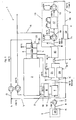
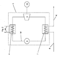
- Fig. 1 shows a schematic block diagram of a stationary power plant 1, wherein the stationary power plant 1 comprises an engine system comprising at least one internal combustion engine 2 and a cryogenic storage system or liquid-air storage device 9, and Fig. 2 shows a more detailed block diagram of a connected to the internal combustion engine 2 energy conversion device 3, which is operated by an organic cycle process according to Rankine (ORC principle).
- ORC principle Rankine
- the internal combustion engine 2 is formed in this example as externally ignited gas Otto engine and connected by means of a heat cycle W with an energy conversion device 3, in particular with a designed as an evaporator first steam process heat exchanger 4 of the energy conversion device 3.
- the heat cycle W transports a waste heat of the internal combustion engine 2 to the first steam process heat exchanger 4, for example, by a cooling circuit of the internal combustion engine 2 (eg engine cooling water circuit and / or engine oil cooling circuit and / or charge air cooling circuit) is connected and promotes its or their coolant through the first steam process heat exchanger 4 ,
- a working medium M is conveyed through the first steam process heat exchanger 4, for example by means of a pump 5, and the waste heat of the internal combustion engine 2 brought by the heat cycle W into the first steam process heat exchanger 4 for evaporation of the Working medium M used.
- the evaporated working medium M is expanded while performing work in a turbine 6 and condensed again in a second steam-process heat exchanger 7 designed as a condenser
- the second steam process heat exchanger 7 is supplied via a cold air line 8 by means of a cold air pump 11 with a liquid cold air K from a liquid air reservoir 25 to a liquid air storage device 9 whose cooling energy is used for cooling and condensing the working medium M.
- the liquid cold air K supplied to the second steam process heat exchanger 7 has a temperature of -160 ° C. in this example. Due to the heat exchange between the working medium M and cold air K in the second steam process heat exchanger 7, the cold air K. This causes evaporation and a first preheating of the cold air K from about -160 ° C to about -90 ° C, the Cold air K after evaporation and preheating has a pressure of about 150 bar.
- the heat required for the evaporation and preheating is provided by the internal combustion engine 2 via the energy conversion device 3, wherein, for example, the sum of the heat from engine cooling water, engine oil and a charge air compressor stage can be used for this purpose.
- the temperature of the heat cycle W or the medium (e.g., cooling water) carried in the heat cycle W is 90 ° C in this example. Due to the very high temperature difference between the medium of the heat cycle W in the first steam process heat exchanger 4 (90 ° C) and the cold air K in the second steam process heat exchanger 7 (-160 ° C), the energy conversion device 3 can achieve a very high efficiency.
- the evaporation of the cold air K by use of engine heat allows the meaningful use of a steam process with a suitable fluid as the working medium M, the engine heat as a heat source for the fluid evaporation and the cold of the cold air K are used for fluid condensation. Due to the relatively large temperature difference of the engine heat and the cold air K, a correspondingly good process efficiency of about 15 - 20% can be achieved, ie approx. 15 - 20% of engine heat can be converted into mechanical or electrical energy.
- a cold air heat exchanger 12 which heats the cold air K and as working air A of a relaxation device 13 supplies.
- the working air A which is strongly heated by the cold air heat exchanger 12 and thus under high pressure, is expanded in two expansion turbines 14, 15 while performing work.
- the expansion turbines 14, 15 are connected to electrical generators that can deliver electrical energy into a connected power grid.
- the cold air K is heated by utilizing exhaust heat of the engine 2 or a plurality of internal combustion engines 2 by supplying hot exhaust gas via an exhaust pipe 16 to the cold air heat exchanger 12.
- the exhaust gas has a temperature of about 360 ° C and allows heating of the cold air K to a temperature of about 300 ° C, in turn, the exhaust gas is cooled to about 120 ° C to 100 ° C.
- the cold air K is at a temperature of about 300 ° C at a pressure of about 150 bar as working air A to the first expansion turbine 14 of the expansion device 13 at. After performing work in the first expansion turbine 14, the working air A has a temperature of 80 ° C at a pressure of about 10 bar.
- the working air A Before entering the second expansion turbine 15, the working air A is heated again in a working air heat exchanger 17.
- the supplied in the working air heat exchanger 17 of the working air A heat can come, inter alia, from the air compression of the liquid storage device 9 by the heat of the compressed air L stored in a recuperative heat storage 31 and if necessary the working air heat exchanger 17 is supplied (see Fig. 3 and Fig. 4 ).
- the temperature of the working air A is raised to about 450 ° C.
- the working air A After performing work in the second expansion turbine 15, the working air A has a temperature of 180 ° C at a pressure of 1 bar.
- the volume flow of the working air A is relatively low due to the very high pressure of about 150 bar before the first expansion turbine 14, so that the required cold air heat exchanger 12 can be kept small and compact.
- the cold air K as a liquid flow through a tube bundle system of the cold air heat exchanger 12, while the engine exhaust gas is passed through corresponding cooling fins.
- a working air heat exchanger 17 which is, for example, with a recuperative heat storage 31, to which the heat of compression was charged during the Lucasverieriungsphase, in heat exchange.
- the heat via intermediate circuits eg first heat storage circuit 35a and second heat storage circuit 35b
- two heat transfer media can be used.
- the temperature range between 50 ° C and about 250 ° C can be a thermal oil and for the temperature range between 250 ° C and 450 ° C, a molten salt can be used.
- An exemplary embodiment of a working air heat exchanger 17 with recuperative heat storage 31 is shown in FIG Fig. 4 shown.
- the working air A at the outlet of the expansion device 13 is supplied via a combustion air line 18 of the internal combustion engine 2 as combustion air V. Since the working air A at the outlet of the expansion device 13 has a temperature of about 180 ° C, takes place in the example shown, a two-stage cooling of the combustion air V. First, the combustion air V in an ambient air heat exchanger 19 with the aid of ambient air L to a temperature of about 50 ° C cooled. The air mass flow of the combustion air to be cooled V is about 20 kg / s. After the first cooling in the ambient air heat exchanger 19, the combustion air V is additionally passed through a combustion air heat exchanger 20.
- the cold air K is used as cooling medium by dividing the cold air K in the cold air line 8 into two partial flows and a first cold air partial flow K 'through the combustion air heat exchanger 20 and a second cold air partial flow K "is passed through a charge air heat exchanger 21.
- K "through the combustion air heat exchanger 20 and the charge air heat exchanger 21 are recombined and supplied as cold air K the cold air heat exchanger 12, in which, as already described, the cold air K, for example, heated from 0 ° C to a temperature of about 300 ° C. and then as working air A of the expansion device 13 is supplied.
- the combustion air V is cooled to a temperature of about 0 ° C to 10 ° C and subsequently the internal combustion engine 2, for example, with the addition of ambient air L and / or fuel supplied as a charge air G.
- charge air G is thus understood as meaning both air and a fuel-air mixture, for example a fuel gas-air mixture for a stationary gas engine.
- the charge air G is compressed in the example shown in a known manner (eg by means of one or multi-stage turbocharger), whereby it has a temperature of about 150 ° C to 200 ° C at full engine load.
- the charge air G is then cooled in a charge air cooling device 22.
- Intercooler In order to lower the combustion temperature, which is a significant factor for the thermal load of the internal combustion engine 2 and for the formation of NO x during combustion, the charge air G in the so-called. Intercooler (intercooler 22) is recooled to the lowest possible values. Depending on the cooling medium (for example ambient air or engine cooling water), recooling to values between 40 and 90 ° C is achieved.
- the cooling medium for example ambient air or engine cooling water
- the intercooler is often carried out in two stages, wherein in the first cooling stage 22a, the combustion air, for example, by the engine cooling water or a heating circuit (eg for a district heating) to about 90 ° C and in the second cooling stage 22b via a Ambient air heat exchanger is cooled further to about 50 ° C.
- the combustion air for example, by the engine cooling water or a heating circuit (eg for a district heating) to about 90 ° C
- a heating circuit eg for a district heating
- Ambient air heat exchanger is cooled further to about 50 ° C.
- the cooling of the charge air G takes place in the in Fig. 1 shown stationary power plant 1 three stages.
- the first cooling stage 22a of the charge air cooling device 22 is part of a first charge air cooling circuit 23, in which a liquid cooling medium such as water circulates.
- the second cooling stage 22b of the charge air cooling device 22 further cools the charge air G using ambient air L.
- the third cooling stage 22c of the charge air cooling device 22 uses the cold air K "flowing through the charge air heat exchanger 21 for further cooling of the charge air G, for example to a temperature of about 5 ° C.
- the third cooling stage 22c of the charge air cooling device 22 and the charge air heat exchanger 21 Part of a second charge air cooling circuit 24, in which a liquid cooling medium circulates.
- the cooling medium is cooled to about -30 ° C. under the action of the cold energy of the cold air K "and is supplied to the charge air cooling device 22 at this temperature.
- a cooling of the charge air G and thus simultaneously a heating of the cooling medium of the second charge air cooling circuit 24 to a temperature of about -10 ° C, with the cooling medium is then fed back to the charge air heat exchanger 21.
- Condensation of the charge air G can be avoided that the supercharged air G, the extremely dry cold air K is supplied to the motor after completion of work in the expansion device 13 as combustion air. Characterized in that is eliminated during the air liquefaction of the cold air K in the liquid air storage device 9 in the air contained humidity, the cold air K is generally very dry. Due to this dryness despite increased cooling of the charge air G no condensation occurs.
- a stationary power plant 1 is therefore provided to cool the working air A after expansion to ambient pressure via a combustion air cooling device (eg ambient air heat exchanger 19 and the combustion air heat exchanger 20) to about 10 ° C and to conduct combustion air V to the air intake system of the internal combustion engine 2.
- a combustion air cooling device eg ambient air heat exchanger 19 and the combustion air heat exchanger 20
- This not only prevents condensate separation in the intercooler, but it is also possible to keep the intake temperature before the compressor of the exhaust gas turbocharger for the phase of peak load operation very low even at high ambient temperatures, which reduces the workload for the exhaust gas turbocharger and the Power reserves of the internal combustion engine 2 increased accordingly.
- the performance of the internal combustion engine 2 or an engine system comprising several internal combustion engines 2 by up to 30% increase.
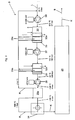
- Fig. 3 1 shows a schematic block diagram of a liquid-air storage device 9.
- An advantageous purpose of a liquid-air storage device 9 or a cryogen storage system is to use the electricity tariffs, which are usually low during periods of power, to charge an energy store (in this case liquid air) and in phases of maximum power consumption As high as possible share of the stored energy in the form of electrical power to the public network and thus contribute to compensate for the power fluctuations.
- ambient air L is cooled in accordance with and stored in a liquid air reservoir 25, such as a tank.
- a liquid air reservoir 25 such as a tank.
- the liquefied cold air K is heated and supplied as working air A of an expansion device 13 in which the energy present in the working air A is partly converted into mechanical work, for example in expansion turbines 14, 15 by coupling generators with the expansion turbines 14th
- peak current can be generated as needed and quickly.
- air L eg ambient air
- air L is compressed at a mass air flow of about 20 kg / s via a two-stage compression by means of a first air compressor 26 and a second air compressor 27 to a pressure of about 180-200 bar, whereby after each compressor Stage a recooling of the air L is provided.
- the air is expanded in an expansion turbine 28 to about 4 bar and after flowing through a first countercurrent heat exchanger 29a in an executed as throttle condensing final stage 34 back to ambient pressure.
- the air temperature drops below the dew point and thereby the air L falls out partly in liquid form.
- the liquid phase of the air L is passed as liquid cold air K in the liquid air reservoir 25 and the gaseous phase of the air L is as recooling air R in corresponding countercurrent heat exchangers 29 a, 29 b, 29 c for Recooling of the air L used in the liquefaction process and / or supplied to the air L prior to the liquefaction process.
- the solution proposed here provides in particular a two-stage compression, wherein in the first stage via a first air compressor 26 in the form of a turbo compressor, a compression of the air L to about 27 bar.
- the temperature of the air L after leaving this compressor is approx. 570 ° C.
- the air L is recooled to about 200 ° C, wherein the heat via two heat storage circuits 35a, 35b is transferred to a recuperative heat storage 31 (see Fig. 4 ).
- the air L is then cooled to about 50 ° C and, after further cooling using the recooled air R in a third countercurrent heat exchanger 29c via an adsorptive filter 33 (eg regenerative activated carbon filter) to a second air compressor 27 passed.
- an adsorptive filter 33 eg regenerative activated carbon filter
- the air L is compressed from 27 bar to about 180 bar, wherein the heat of compression is dissipated into the environment.
- a second air heat exchanger 32b and a second countercurrent heat exchanger 29b which is flowed through by the recooling air R from the liquefaction output stage 34, a further cooling to about -30 ° C and a further purification in an adsorptive filter 33th
- the second air compressor 27 can basically also be designed as a turbocompressor. Due to the already at the very high pressure level relatively low flow rate, however, screw compressors are preferably used with internal oil cooling, which lead to correspondingly reduced compression temperatures.
- the purpose of the two-stage compression with intermediate cooling is that it can greatly reduce the total workload required for air compression (reduction by approx. 40%) and ideally combine different compressor technologies.
- the specific proposed solution provides for the adjustment of the compressor stages so that the air L in the first air compressor 26 is compressed to a pressure of approximately 27 bar and in the second air compressor 27 the remaining compression takes place at approximately 180-200 bar. According to the different compression ratios thus account for about two-thirds of the total compression work on the first air compressor 26.
- the rationale for this asymmetry in power distribution is that thereby a sufficiently high temperature for the transferred to a recuperative heat storage 31 heat and subsequently for in a connected working air heat exchanger 17 heated working air A is achieved.
- FIG. 4 schematically a recuperative heat storage 31 and thus interconnected heat exchanger (heat storage heat exchanger 30 and working air heat exchanger 17) and the corresponding heat fluxes are shown.
- the heat exchangers 17, 30 and the recuperative heat storage 31 are designed in two parts, so that in each case one for the respective temperature range optimally suitable heat exchange medium can be used.
- a first temperature range between 80 ° C and about 300 ° C is in a first heat storage circuit 35a preferably a thermal oil (stored in a first reservoir 38a) and in a second temperature range between about 270 ° C and 460 ° C in a second Heat storage circuit 35b preferably a molten salt (stored in a second reservoir 38b) used.
- the piping or interconnection of the heat storage circuits 35a, 35b takes place in such a way that for both heat exchanger media (in this case thermal oil and molten salt) in each case only one circulation system with two pumps 36 and two Shut-off devices 37 is necessary, depending on the operating mode, the flow of the respective heat exchanger medium can be controlled by heat storage heat exchanger 30 and / or working air heat exchanger 17.
- the overall system can thus be kept very simple.
- the combined power plant (engine plant and Cryogen storage facility) can feed in this calculation example in total a peak power of about 26 MW in the power grid, compared to 10 MW in rated load operation of the engine system. For a period of a few hours, the power plant output can be increased by approx. 2.6 times using a combination of engine system and Cryogen storage system become. Conversely, a power of about 16 MW can be taken out of the grid in the short term in order to fill the energy stores (cold liquid air K in the liquid air reservoir 25 and heat in the recuperative heat store 31).
- the load changes can be made in a relatively short time.
- the period of time from the peak demand request, or the time the Cogenogen power plant startup command is issued, to peak load is only about 10 to 15 minutes. This is a much shorter time span than, for example, modern gas and steam combined cycle power plants need to come from standstill to full load. In such power plants, this period is usually several hours.
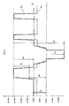
- Fig. 5 an example of an operational management of a stationary power plant 1 according to the proposed concept is shown, wherein the stationary power plant 1 comprises an engine system comprising at least one internal combustion engine 2 and a cryogenic storage facility or liquid-air storage device 9.
- the solid mecanicnverfholz P A shows an example of the course of the power output or power consumption of the stationary power plant 1 over time t and the dashed line P G is to indicate the engine power plant supplied fuel power over time t.
- the nominal load P N of the engine system which comprises at least one internal combustion engine 2 is assumed to be 10 MW.
- the power output of the stationary power plant 1 rises in a steep ramp to about 26 MW and remains at this level until the request is taken out again and the power output back to the nominal load level P N within 1 to 2 min.
- the maximum power output of about 26 MW is on the one hand by increasing the power output of the engine system to about 13 MW (shown by arrow 39) and on the other hand by exhausting the power output of the expansion device 13 of about 13 MW (represented by arrow 40) reached. Overall, this results in an illustrated by the arrow 41 peak load connection potential of about 16 MW compared to rated load operation of the engine system.
- cryogenic storage system or the liquid-air storage device 9 is set to storage filling operation and takes about 15 MW from the network (represented by arrow 42).
- the arrow 43 represents the total load variability of a proposed stationary power plant 1 comprising an engine plant and a cryogen storage facility. If the stationary power plant 1, however, only an engine plant and no Cryogen storage facility include the load variability would correspond only to the rated load P N of the engine system, as In this case, neither an additional load could be exploited by a relaxation device 13 nor an increase in the power output of the engine system could be achieved by more efficient cooling mechanisms.
- the load changes or changes in the power output of the stationary power plant 1 can basically also be implemented in a continuous form and, for example, adapted to the consumer characteristics.
- the proposed plant concept allows a maximum variability of the power output of a stationary power plant based on an integrative combination of a gas or diesel-powered engine power plant with energy buffering via liquid air technology.
- the power consumption of a power plant can be timely adapted to the current conditions of power consumption and power generation in the public network and be contributed by maximum span between power and power to stabilize the power grid , in which efficient intermediate storage of energy can shift the proportion of electrical power from low tariff to high tariff times.
- the proposed plant concept is aimed particularly at the power generation industry, with a particular focus on power plant technologies. Generating electrical power with maximum flexibility and including short and medium term storage to compensate for asynchronous generation and consumption fluctuations in the public grid.
- this is a power plant based on an engine plant (e.g., a gas or diesel engine power plant), and a power plant based on the expansion of stored liquefied air.
- an engine plant e.g., a gas or diesel engine power plant
- a power plant based on the expansion of stored liquefied air e.g., a gas or diesel engine power plant
Landscapes
- Engineering & Computer Science (AREA)
- Mechanical Engineering (AREA)
- General Engineering & Computer Science (AREA)
- Chemical & Material Sciences (AREA)
- Combustion & Propulsion (AREA)
- Physics & Mathematics (AREA)
- Thermal Sciences (AREA)
- Engine Equipment That Uses Special Cycles (AREA)
Applications Claiming Priority (1)
| Application Number | Priority Date | Filing Date | Title |
|---|---|---|---|
| AT18972011 | 2011-12-28 |
Publications (2)
| Publication Number | Publication Date |
|---|---|
| EP2610470A2 true EP2610470A2 (fr) | 2013-07-03 |
| EP2610470A3 EP2610470A3 (fr) | 2015-12-02 |
Family
ID=47227421
Family Applications (1)
| Application Number | Title | Priority Date | Filing Date |
|---|---|---|---|
| EP12007808.4A Withdrawn EP2610470A3 (fr) | 2011-12-28 | 2012-11-19 | Procédé de fonctionnement d'une centrale stationnaire avec au moins un moteur à combustion interne |
Country Status (2)
| Country | Link |
|---|---|
| EP (1) | EP2610470A3 (fr) |
| AT (1) | AT12844U1 (fr) |
Cited By (11)
| Publication number | Priority date | Publication date | Assignee | Title |
|---|---|---|---|---|
| US20150184590A1 (en) * | 2013-12-30 | 2015-07-02 | William M. Conlon | Liquid air power and storage |
| CN108507228A (zh) * | 2017-02-28 | 2018-09-07 | 全球能源互联网研究院有限公司 | 一种用于冷热电联供的电能替代方法及冷热电联供系统 |
| CN110903110A (zh) * | 2019-11-25 | 2020-03-24 | 浙江万泰环境工程有限公司 | 一种沼渣快速好氧成肥系统 |
| US10738696B2 (en) | 2015-06-03 | 2020-08-11 | William M. Conlon | Liquid air power and storage with carbon capture |
| US11073080B2 (en) | 2015-10-21 | 2021-07-27 | William M. Conlon | High pressure liquid air power and storage |
| US11221177B2 (en) | 2015-06-16 | 2022-01-11 | William M Conlon | Cryogenic liquid energy storage |
| IT202000030023A1 (it) * | 2020-12-04 | 2022-06-04 | Nuovo Pignone Tecnologie Srl | Un sistema per produrre gas naturale liquefatto e metodo |
| US11421560B2 (en) | 2015-06-01 | 2022-08-23 | William M. Conlon | Part load operation of liquid air power and storage system |
| CN115218506A (zh) * | 2020-12-13 | 2022-10-21 | 李华玉 | 回热式热力循环与中间回热机械压缩式热泵 |
| CN115419484A (zh) * | 2022-07-26 | 2022-12-02 | 合肥通用机械研究院有限公司 | 一种应用于试车台燃气冷却流程的储能固碳系统 |
| CN117663556A (zh) * | 2022-08-31 | 2024-03-08 | 青岛海尔空调电子有限公司 | 用于控制磁悬浮系统的方法及装置、磁悬浮系统 |
Families Citing this family (2)
| Publication number | Priority date | Publication date | Assignee | Title |
|---|---|---|---|---|
| DE102014105237B3 (de) | 2014-04-11 | 2015-04-09 | Mitsubishi Hitachi Power Systems Europe Gmbh | Verfahren und Vorrichtung zum Speichern und Rückgewinnen von Energie |
| CN111577418A (zh) * | 2020-05-28 | 2020-08-25 | 中国船舶工业集团公司第七0八研究所 | 一种fsru上超临界三级级联朗肯循环发电系统 |
Family Cites Families (4)
| Publication number | Priority date | Publication date | Assignee | Title |
|---|---|---|---|---|
| NL7600308A (nl) * | 1975-02-07 | 1976-08-10 | Sulzer Ag | Werkwijze en inrichting voor het verdampen en verwarmen van vloeibaar natuurlijk gas. |
| BE857421A (fr) * | 1977-08-03 | 1978-02-03 | Acec | Installation de production d'energie electrique comprenant des machines thermiques associees a la revaporisation d'un gaz liquefie |
| US6166317A (en) * | 1999-02-18 | 2000-12-26 | Volk, Jr.; Joseph A. | Cryogenic thermoelectric generator |
| US8020388B2 (en) * | 2005-08-05 | 2011-09-20 | Siemens Aktiengesellschaft | Method for increasing the efficiency of a combined gas/steam power station with integrated gasification combined cycle |
-
2011
- 2011-12-28 AT ATGM8060/2012U patent/AT12844U1/de not_active IP Right Cessation
-
2012
- 2012-11-19 EP EP12007808.4A patent/EP2610470A3/fr not_active Withdrawn
Cited By (18)
| Publication number | Priority date | Publication date | Assignee | Title |
|---|---|---|---|---|
| US12385432B2 (en) * | 2013-12-30 | 2025-08-12 | Pintail Power Llc | Liquid air power and storage |
| US10473029B2 (en) * | 2013-12-30 | 2019-11-12 | William M. Conlon | Liquid air power and storage |
| US20240328350A1 (en) * | 2013-12-30 | 2024-10-03 | Pintail Power Llc | Liquid air power and storage |
| US20150184590A1 (en) * | 2013-12-30 | 2015-07-02 | William M. Conlon | Liquid air power and storage |
| US11421560B2 (en) | 2015-06-01 | 2022-08-23 | William M. Conlon | Part load operation of liquid air power and storage system |
| US10738696B2 (en) | 2015-06-03 | 2020-08-11 | William M. Conlon | Liquid air power and storage with carbon capture |
| US11686527B2 (en) | 2015-06-16 | 2023-06-27 | Pintail Power Llc | Cryogenic liquid energy storage |
| US11221177B2 (en) | 2015-06-16 | 2022-01-11 | William M Conlon | Cryogenic liquid energy storage |
| US11674439B2 (en) | 2015-10-21 | 2023-06-13 | Pintail Power Llc | High pressure liquid air power and storage |
| US11073080B2 (en) | 2015-10-21 | 2021-07-27 | William M. Conlon | High pressure liquid air power and storage |
| CN108507228A (zh) * | 2017-02-28 | 2018-09-07 | 全球能源互联网研究院有限公司 | 一种用于冷热电联供的电能替代方法及冷热电联供系统 |
| CN110903110A (zh) * | 2019-11-25 | 2020-03-24 | 浙江万泰环境工程有限公司 | 一种沼渣快速好氧成肥系统 |
| WO2022117228A1 (fr) * | 2020-12-04 | 2022-06-09 | Nuovo Pignone Tecnologie - S.R.L. | Système pour la production de gaz naturel liquéfié et procédé |
| IT202000030023A1 (it) * | 2020-12-04 | 2022-06-04 | Nuovo Pignone Tecnologie Srl | Un sistema per produrre gas naturale liquefatto e metodo |
| CN115218506A (zh) * | 2020-12-13 | 2022-10-21 | 李华玉 | 回热式热力循环与中间回热机械压缩式热泵 |
| CN115419484A (zh) * | 2022-07-26 | 2022-12-02 | 合肥通用机械研究院有限公司 | 一种应用于试车台燃气冷却流程的储能固碳系统 |
| CN115419484B (zh) * | 2022-07-26 | 2024-02-02 | 合肥通用机械研究院有限公司 | 一种应用于试车台燃气冷却流程的储能固碳系统 |
| CN117663556A (zh) * | 2022-08-31 | 2024-03-08 | 青岛海尔空调电子有限公司 | 用于控制磁悬浮系统的方法及装置、磁悬浮系统 |
Also Published As
| Publication number | Publication date |
|---|---|
| EP2610470A3 (fr) | 2015-12-02 |
| AT12844U1 (de) | 2012-12-15 |
Similar Documents
| Publication | Publication Date | Title |
|---|---|---|
| AT12844U1 (de) | Verfahren zum Betreiben einer stationären Kraftanlage mit wenigstens einer Brennkraftmaschine | |
| DE102010027302B4 (de) | Energiespeichersystem | |
| EP1053438B1 (fr) | Procede et appareil de transformation de chaleur pour la production de milieux chauds | |
| EP3129610A1 (fr) | Procédé et dispositif d'accumulation et de récupération d'énergie | |
| DE102010050428A1 (de) | Druckstufen-Wärme-Speicherkraftwerk bzw. Energiespeicherverfahren zum zeitweiligen Speichern von Energie in Form von Druckenergie in einem kompressiblen Medium und in Form von Wärmeenergie | |
| DE19757588A1 (de) | Stromerzeugungssystem mit Gasturbine und Energiespeicher | |
| EP4251859B1 (fr) | Système et procédé de stockage d'énergie électrique sous forme d'énergie thermique et de libération de celle-ci | |
| AT503557B1 (de) | Kälteanlage und verfahren zum betrieb einer kälteanlage | |
| WO2016131920A1 (fr) | Centrale à vapeur et procédé pour son fonctionnement | |
| WO2012013289A2 (fr) | Procédé et dispositif de stockage de courant | |
| WO2010136454A1 (fr) | Dispositif de thermorégulation de l'air d'admission et procédé de fonctionnement | |
| EP3080407A1 (fr) | Accumulation d'énergie au moyen d'un accumulateur de chaleur et d'un thermocompresseur de vapeur | |
| EP4139562B1 (fr) | Système comprenant un dispositif de production d'électricité et de stockage d'énergie à air liquide | |
| EP2610445A2 (fr) | Procédé de fonctionnement d'une centrale stationnaire avec au moins un moteur à combustion interne | |
| DE202005003611U1 (de) | Wärmekraftwerk mit Druckluftspeichervorrichtung zum Ausgleich fluktuierender Energieeinspeisung aus regenerativen Energiequellen | |
| DE102012110579B4 (de) | Anlage und Verfahren zur Erzeugung von Prozessdampf | |
| EP2574738A1 (fr) | Installation de stockage d'énergie thermique | |
| DE3000044A1 (de) | Verfahren und vorrichtung zur rueckgewinnung von verlustenegie aus der kombination eines gaskompressors und eines antriebsmotors fuer den kompressor | |
| EP2470755A2 (fr) | Procédé de récupération de la chaleur perdue de moteurs à combustion interne | |
| EP2951407A2 (fr) | Procédé permettant de faire fonctionner une centrale basse température et centrale basse température | |
| EP2976511A1 (fr) | Procédé et dispositif pour produire de l'énergie électrique | |
| WO2015055294A1 (fr) | Stockage d'électricité par accumulateur thermique et turbine à air | |
| DE102013016461A1 (de) | Verfahren zum Betrieb eines Niedertemperaturkraftwerkes, sowie Niedertemperaturkraftwerk selbst | |
| EP2708719A1 (fr) | Centrale à gaz destinée à accumuler de l'énergie | |
| DE102013001478B4 (de) | Verfahren zum Betrieb eines Niedertemperaturkraftwerkes, sowie Niedertemperaturkraftwerk selbst |
Legal Events
| Date | Code | Title | Description |
|---|---|---|---|
| PUAI | Public reference made under article 153(3) epc to a published international application that has entered the european phase |
Free format text: ORIGINAL CODE: 0009012 |
|
| AK | Designated contracting states |
Kind code of ref document: A2 Designated state(s): AL AT BE BG CH CY CZ DE DK EE ES FI FR GB GR HR HU IE IS IT LI LT LU LV MC MK MT NL NO PL PT RO RS SE SI SK SM TR |
|
| AX | Request for extension of the european patent |
Extension state: BA ME |
|
| PUAL | Search report despatched |
Free format text: ORIGINAL CODE: 0009013 |
|
| AK | Designated contracting states |
Kind code of ref document: A3 Designated state(s): AL AT BE BG CH CY CZ DE DK EE ES FI FR GB GR HR HU IE IS IT LI LT LU LV MC MK MT NL NO PL PT RO RS SE SI SK SM TR |
|
| AX | Request for extension of the european patent |
Extension state: BA ME |
|
| RIC1 | Information provided on ipc code assigned before grant |
Ipc: F02G 5/00 20060101ALI20151023BHEP Ipc: F02G 5/02 20060101AFI20151023BHEP Ipc: F02G 5/04 20060101ALI20151023BHEP Ipc: F01K 23/06 20060101ALI20151023BHEP Ipc: F01K 9/00 20060101ALI20151023BHEP |
|
| STAA | Information on the status of an ep patent application or granted ep patent |
Free format text: STATUS: THE APPLICATION IS DEEMED TO BE WITHDRAWN |
|
| 18D | Application deemed to be withdrawn |
Effective date: 20160603 |