EP4251859B1 - Système et procédé de stockage d'énergie électrique sous forme d'énergie thermique et de libération de celle-ci - Google Patents
Système et procédé de stockage d'énergie électrique sous forme d'énergie thermique et de libération de celle-ci Download PDFInfo
- Publication number
- EP4251859B1 EP4251859B1 EP21816344.2A EP21816344A EP4251859B1 EP 4251859 B1 EP4251859 B1 EP 4251859B1 EP 21816344 A EP21816344 A EP 21816344A EP 4251859 B1 EP4251859 B1 EP 4251859B1
- Authority
- EP
- European Patent Office
- Prior art keywords
- temperature heat
- heat
- temperature
- circuit
- low
- Prior art date
- Legal status (The legal status is an assumption and is not a legal conclusion. Google has not performed a legal analysis and makes no representation as to the accuracy of the status listed.)
- Active
Links
Images

Classifications
-
- F—MECHANICAL ENGINEERING; LIGHTING; HEATING; WEAPONS; BLASTING
- F01—MACHINES OR ENGINES IN GENERAL; ENGINE PLANTS IN GENERAL; STEAM ENGINES
- F01K—STEAM ENGINE PLANTS; STEAM ACCUMULATORS; ENGINE PLANTS NOT OTHERWISE PROVIDED FOR; ENGINES USING SPECIAL WORKING FLUIDS OR CYCLES
- F01K3/00—Plants characterised by the use of steam or heat accumulators, or intermediate steam heaters, therein
- F01K3/12—Plants characterised by the use of steam or heat accumulators, or intermediate steam heaters, therein having two or more accumulators
-
- F—MECHANICAL ENGINEERING; LIGHTING; HEATING; WEAPONS; BLASTING
- F01—MACHINES OR ENGINES IN GENERAL; ENGINE PLANTS IN GENERAL; STEAM ENGINES
- F01K—STEAM ENGINE PLANTS; STEAM ACCUMULATORS; ENGINE PLANTS NOT OTHERWISE PROVIDED FOR; ENGINES USING SPECIAL WORKING FLUIDS OR CYCLES
- F01K3/00—Plants characterised by the use of steam or heat accumulators, or intermediate steam heaters, therein
- F01K3/18—Plants characterised by the use of steam or heat accumulators, or intermediate steam heaters, therein having heaters
-
- Y—GENERAL TAGGING OF NEW TECHNOLOGICAL DEVELOPMENTS; GENERAL TAGGING OF CROSS-SECTIONAL TECHNOLOGIES SPANNING OVER SEVERAL SECTIONS OF THE IPC; TECHNICAL SUBJECTS COVERED BY FORMER USPC CROSS-REFERENCE ART COLLECTIONS [XRACs] AND DIGESTS
- Y02—TECHNOLOGIES OR APPLICATIONS FOR MITIGATION OR ADAPTATION AGAINST CLIMATE CHANGE
- Y02E—REDUCTION OF GREENHOUSE GAS [GHG] EMISSIONS, RELATED TO ENERGY GENERATION, TRANSMISSION OR DISTRIBUTION
- Y02E20/00—Combustion technologies with mitigation potential
- Y02E20/14—Combined heat and power generation [CHP]
Definitions
- the invention relates to a system for storing and delivering electrical energy with its storage as thermal energy, according to the preamble of claim 1.
- the invention also relates to a method for storing and delivering electrical energy with its storage as thermal energy.
- Electricity from renewable energy sources such as wind power and photovoltaics is very variable in its supply.
- demand for electricity also fluctuates over the course of a day.
- Energy storage systems can be used to store electrical energy at times of excess supply and make it available again when there is demand.
- One option for this is thermoelectric energy storage (TEES), which converts electrical energy into heat during a charging process and uses this heat to generate electricity again when it is needed during a discharging process.
- TEES thermoelectric energy storage
- previously unused heat can be stored and made usable using thermal storage systems.
- the efficiency of such energy storage systems can be further increased by not generating the heat directly via an electrical resistance heater, but indirectly by using the electrical energy to operate a heat pump.
- Such an energy storage system is, for example, made of EP 3 054 155 A1 or from US 2016 / 222 830 A1 known. It comprises a heat pump, a water vapor circuit, a first heat storage system and a second heat storage system.
- the heat pump system can be any desired.
- the preferred working medium is CO2 or air.
- the first heat storage system contains a heat transfer medium that is heated by a working medium of the heat pump.
- the second heat storage system preferably works with water as a heat transfer medium, which is heated with the condensate of the water vapor circuit during a discharging process.
- the heated water is stored in a separate hot water tank and fed to the heat pump during a loading process, where it heats the working medium flowing out of the expander before it is fed into a separate cold water tank.
- the heat transfer medium of the first heat storage system is brought to its final temperature in two stages. In a first stage, a standard compressor compresses the working medium of the heat pump to a temperature of 300°C to 400°C, which then releases its heat to the heat transfer medium of the first heat storage system. In a second step, the heat transfer medium is brought to its final temperature using a regulated electric heater. This approach eliminates the need to design the heat pump components for high temperature conditions. This is only necessary for the components downstream of the electric heater necessary.
- the disadvantage is that the overall efficiency drops due to the conversion of high-quality electrical energy into low-quality thermal energy.
- the heat storage units of the two heat storage systems can be designed as stratified storage units.
- the first heat storage system can also receive external heat, for example from a solar power plant.
- EP 2 942 492 A1 A similar energy storage system is EP 2 942 492 A1
- heat coupling of the second heat storage system with the heat pump takes place through heat exchangers upstream and downstream of the expander.
- the EP 2 653 668 A1 relates to an energy storage system in which both the charging cycle and the discharging cycle are designed as a Rankine process. Heat can be coupled into the heat pump operated in the charging cycle via a second heat pump.
- the heat storage system is designed as a large-volume stratified storage system with an aqueous salt solution as the heat storage medium.
- the stored heat is released either as thermal heating energy or as electrical energy via an ORC heat power process.
- the invention is based on the finding that a system (such as that consisting of EP 3 054 155 A1 known), in which the residual heat of the condensate from the air condenser is transferred to an LT heat carrier via a low-temperature (LT) heat exchanger and this is then fed into an LT hot storage tank, has the disadvantage that the condensate must have a higher temperature than the LT heat carrier in order for heat to be transferred at all. If the size of the LT heat exchanger is to be minimized, a correspondingly large temperature difference is necessary. For a desired condensate temperature, the pressure is also specified because of operation in the wet steam region.
- LT low-temperature
- both the condensate as a heating medium and the LT heat transfer medium are liquid, which leads to only a limited heat transfer in the liquid-liquid LT heat exchanger due to the resulting relatively small mass flow.
- the NT heat exchanger is designed as a condenser and is operated with steam from the steam turbine unit.
- Steam has the advantage that it has a greater energy content than condensate and that the condensing steam has a better heat transfer. Both factors mean that, with the same heat flow, the heat exchanger according to the invention can be made much smaller and is more flexible in operation.
- a further advantage is achieved by the fact that the steam turbine can relax to lower pressures and temperatures, which increases its efficiency. In this way, the energy introduced into an energy storage system is used to an extremely high degree, thereby achieving an economical solution with a high level of efficiency, whereby commercially available components can be used.
- the system can be operated symmetrically or asymmetrically, i.e. loading times and discharging times can differ and the energy input and output - whether electrical or thermal - can also differ and be adapted to the respective boundary conditions.
- the energy source used to charge the thermal storage is preferably electricity-based, but is not limited to this. It is also possible to feed heat energy directly into the thermal storage. If the heat is available at a lower temperature than that of the storage, it can be transferred to the working fluid of the heat pump using another heat pump. It is also possible to transfer the heat from the HT heat storage circuit to an external heat consumer. This can be used to provide process heat, for example, a Gas streams can be heated or useful steam can be generated, which can be used directly or converted back into electricity using a steam turbine and generator. There is also the option of providing cold from the heat pump process.
- the steam turbine unit has a high-pressure turbine and a medium-pressure/low-pressure turbine, and an intermediate superheater is arranged between the high-pressure turbine and the medium-pressure/low-pressure turbine.
- an intermediate superheater is arranged between the high-pressure turbine and the medium-pressure/low-pressure turbine.
- the high temperature of the intermediate superheater operated with the high-temperature heat transfer medium leads to an increase in efficiency.
- Part of the high-temperature heat transfer medium flows through the intermediate superheater before entering the steam generation unit.
- the low-temperature heat storage circuit is particularly advantageous in locations where no high-temperature heat source is available for the heat pump and ambient air would otherwise be used as a heat source.
- the higher temperature starting level increases the heat pump's coefficient of performance.
- the heat exchangers can be built much smaller because the heat transfer from the liquid phase to the heat pump working medium is significantly better than from air to the heat pump working medium.
- the heat pump circuit also has a recuperator and an expander and the first working medium flows through the compressor, the high-temperature heat exchanger, the recuperator, the expander, the working medium heater and the recuperator again in succession.
- the desired inlet temperature of the working medium in the HT heat exchanger is provided solely by the compression heat generated in the compressor.
- the compressor must be designed to be temperature-resistant. Corresponding measures are known from gas turbine technology. By dispensing with thermal support from an electrical resistance heater, this design achieves a particularly high level of efficiency.
- the expander is preferably operated in the positive Celsius temperature range. This increases operational reliability, as no phase changes occur with icing of the working medium.
- the high-temperature heat storage circuit further comprises a high-temperature cold storage unit and a high-temperature hot storage unit, and the high-temperature heat transfer medium flows successively through the high-temperature cold storage unit, the high-temperature heat exchanger, the high-temperature hot storage unit and the steam generation unit. Due to the high temperature of the high-temperature heat transfer medium, steam with a correspondingly high temperature and high pressure can be generated, which has a positive effect on the efficiency of the re-conversion circuit.
- the heat pump circuit has a second compressor and the heat pump circuit and the high-temperature heat storage circuit are connected to a second high-temperature heat exchanger for transferring heat from the first working medium to the high-temperature heat carrier, wherein in the heat pump circuit the second compressor is arranged downstream of the (first) high-temperature heat exchanger and the second high-temperature heat exchanger is arranged downstream of the second compressor, and wherein in the high-temperature heat storage circuit the second high-temperature heat exchanger can be connected in parallel to the high-temperature heat exchanger.
- the compressor, the expander and the second compressor are mechanically coupled to one another via a common gear.
- friction losses are reduced, which has a positive effect on the mechanical efficiency.
- an electric heater is arranged in the high-temperature heat storage circuit between the high-temperature heat exchanger(s) and the high-temperature hot storage tank. This allows the HT heat transfer medium to be heated extremely precisely to the desired target temperature shortly before entering the HT hot storage tank.
- the steam generation unit has a high-temperature preheater, a steam generator and a superheater, through which the second working medium flows in this order and the high-temperature heat transfer medium flows in countercurrent.
- the high-temperature heat transfer medium outlet of the high-temperature preheater is advantageously connected to the inlet of the high-temperature cold storage tank. The gradual release of the thermal energy of the HT heat transfer medium to generate steam leads to effective use.
- the low-temperature heat storage circuit has at least one further condenser downstream of the first condenser, whereby all of these condensers are connected in parallel to one another in the reconversion circuit and further condensers arranged downstream one after the other in the low-temperature heat storage circuit are each connected to a bleed line of the steam turbine unit at points between its inlet and outlet, which are arranged upstream one after the other in the reconversion circuit.
- the size of the condensers decreases as their number increases. The storage efficiency increases by gradually increasing the temperature of the NT heat transfer medium.
- the low-temperature heat storage circuit downstream of the last condenser has a storage device for the low-temperature heat carrier with a storage area for cold low-temperature heat carrier and a storage area for warm low-temperature heat carrier, wherein the inlet of the first condenser is connected to the storage area for cold low-temperature heat carrier and the outlet of the last condenser is connected to the storage area for warm low-temperature heat carrier, and the working medium heater is connected to the storage area for warm low-temperature heat carrier.
- the storage facility for the low-temperature heat transfer medium is a stratified storage tank in which both cold and hot water can be stored together.
- a stratified storage tank in which both cold and hot water can be stored together.
- the pressureless operation of the stratified storage tank further reduces investment costs and minimizes operating costs.
- the different temperature ranges are thermally separated from one another by suitable measures.
- the supply and removal of water at different temperatures is carried out by known devices that supply or remove the water at different temperatures at suitable points.
- additional heat storage media is optionally possible, such as solids, e.g. stones or ceramics, for storing sensible heat or phase change materials for storing latent heat.
- the re-electrification circuit comprises at least one low-pressure preheater which is arranged downstream of parallel-connected condensers and is connected to a bleed line of the steam turbine unit at points between its inlet and outlet.
- a tapping line branches off upstream of the at least one further condenser and the at least one low-pressure preheater and is connected to their respective inlet for the second working medium.
- This connection allows flexible use of the thermal energy.
- the proportion of thermal energy that can be released can be changed either in favor of the reconversion cycle or in favor of the low-temperature heat storage cycle.
- At least one high-pressure preheater is arranged in the re-electrification circuit upstream of the steam generation unit, which is connected to the high-pressure turbine for operation via a bleed line.
- the re-conversion circuit has a connection for an external heat consumer.
- the system thus not only enables the recovery of electrical power, but also the extraction of thermal energy from the re-conversion circuit to external heat consumers.
- the system can thus be flexibly adapted to the needs of a user who requires both thermal energy and electrical energy.
- the (first) high-temperature heat exchanger is designed such that the average temperature difference between the first working medium and the high-temperature heat carrier is in a range from 5 K to 30 K and preferably in a range from 8 K to 12 K.
- This mode of operation increases the efficiency of the heat exchanger.
- the HT heat exchanger is divided into several units that are correspondingly smaller and are operated with smaller average temperature differences.
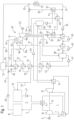
- the Fig. 1 The system shown serves to store energy in a charging process and to make it available again at a later time in a discharging process.
- the system according to the invention is particularly suitable for receiving electrical power from renewable energy sources or surplus power from the power grid.
- Thermal energy can also be coupled directly or indirectly via heat pumps at various points in the system, whereby heat can also be released to cold users in the form of cold.
- the system can also be discharged in several ways.
- the preferred method is to reconvert the energy into electricity by generating steam, which drives a steam turbine and an electricity generator.
- Another way of using the steam generated is to provide at least some of the process heat. Direct use of the thermal energy is also possible.
- the system comprises a heat pump circuit 1 and a re-conversion circuit 2. Both circuits are thermally connected to a high-temperature (HT) heat storage circuit 3 and a Low temperature (NT) heat storage circuit 4.
- HT high-temperature
- NT Low temperature
- a high temperature (HT) heat carrier 5 circulates in the HT heat storage circuit 3
- NT low temperature
- the terms "high temperature” and "low temperature” in the sense of this invention mean that the entire temperature operating range of the HT heat storage circuit 3 is above that of the NT heat storage circuit 4 and that there is generally no overlap.
- Each heat storage circuit also has areas in which the respective heat carrier is "hot” or "cold".
- the heat pump circuit 1 electrical energy is converted into thermal energy during a loading process. It is a closed circuit in which a working medium 7 circulates in a reverse Brayton cycle.
- the type of working medium 7 is not particularly restricted, but dry air, CO2, water vapor or helium are preferred, with dry air being particularly preferred as a readily available and inexpensive working medium.
- the working medium 7 of the heat pump circuit 1 is first preheated in a recuperator 8. Like all other heat exchangers in the entire system, this is preferably operated in countercurrent.
- the electrical energy is supplied to the heat pump circuit 1 by an electric motor 9, which drives a compressor 10.
- the compressor 10 compresses the working medium 7 flowing out of the recuperator 8, which heats up as a result of the compression process.
- the working medium 7 heated in this way gives off its heat to the HT heat carrier 5 in a high-temperature (HT) heat exchanger 11.
- the working medium 7 is then led through the aforementioned recuperator 8 and heats the working medium 7 flowing into the compressor 10. This is then led into an expander 12.
- the mechanical work recovered there is transferred to the compressor 10 via a shaft 13.
- both compressor 10 and expander 12 are designed as single-stage, but they can be designed individually or both as multi-stage.
- the temperature of the working medium 7 decreases due to the relaxation.
- a working medium heater 14 operated with the NT heat transfer medium 6 heat is transferred to the working medium 7 and thus coupled into the heat pump circuit 1. This restores the initial state of the cycle.
- the heat can be coupled at different temperature levels. It is possible to couple even more heat into the heat pump circuit using additional heat exchangers not shown here.
- the heat introduced can come from various sources, for example from waste heat from industrial processes or from one or more heat pumps.
- dry air is used as the working medium 7. Downstream of the compressor 10, this has a pressure of 53 bar and a temperature of 560°C. After heat transfer in the HT heat exchanger 11, the working medium 7 cools down to e.g. 308°C. After passing through the recuperator 8, it cools down to 104°C. In the expander 12, the working medium 7 expands to a pressure of 15 bar at a temperature of 2°C. The system is designed so that no liquid forms during expansion in the expander 12. In the working medium heater 14, the working medium 7 absorbs heat again and now has a temperature of 90°C. Further heat is absorbed in the recuperator 8, causing the temperature to rise to 298°C. In this state, the working medium 7 then enters the compressor 10.
- the HT heat storage circuit 3 has an HT cold storage 15 for storing the cold HT heat carrier 5 and an HT hot storage 16 for storing the hot HT heat carrier 5.
- the type of HT heat carrier 5 is not particularly limited, but molten salts are preferred, e.g. solar salt, which consists of a mixture of 60% by weight sodium nitrate and 40% by weight potassium nitrate. This salt has a large temperature operating range between 290°C and 570°C, high thermal stability and the advantage of pressureless operation.
- the heat storage medium of the HT heat storage 16 and optionally the HT cold storage 15 can consist of the HT heat carrier 5 itself or additionally of solid heat storage media such as rock, ceramic, concrete or phase change materials.
- the HT heat storage circuit 3 preferably forms a closed circuit.
- the HT heat carrier 5 is pumped from the HT cold storage tank 15 with a pump 17 through the HT heat exchanger 11, where it absorbs heat from the working medium 7 of the heat pump circuit 1 and is then fed into the HT hot storage tank 16.
- the HT heat exchanger 11 thus couples the heat pump circuit 1 with the HT heat storage circuit 3.
- the HT heat carrier 5 can also be heated by absorbing heat via separate lines (not shown here) from external heat sources, such as from thermal solar power plants, electric heaters or from waste heat from other processes.
- the HT heat transfer medium 5 has a temperature of 298°C in the HT cold tank 15 and is heated to 550°C during the loading process in the HT heat exchanger 14.
- the HT heat exchanger 11 is designed such that the average temperature difference between the working medium 7 and the HT heat transfer medium 5 is preferably in a range from 5 K to 30 K and particularly preferably in a range from 8 K to 12 K.
- the re-conversion circuit 2 forms the discharge process in which the thermal energy stored in the HT heat storage circuit 3 is converted back into electrical current. The thermal energy is coupled into the re-conversion circuit 2 at several points.
- the re-conversion circuit 2 is also connected to an NT heat storage circuit 4, with which the residual heat from the re-conversion circuit 2 is stored and returned to the heat pump circuit 1 during the loading process. This heat transfer from the re-conversion circuit 2 to the NT heat storage circuit 4 also takes place at several points.
- a second working medium 18 circulates in the re-electrification circuit 2.
- water/steam is used here. Therefore, the embodiment of a re-electrification circuit 2 given here is described using water/steam as the second working medium 18.
- the second working medium 18 passes through the states of matter: liquid, vaporized, condensed.
- a steam turbine unit 19 is located in the reconversion circuit 2. This is optionally designed in two parts with a high-pressure (HP) turbine 19a and a medium-pressure-low-pressure (MD/LP) turbine 19b.
- HP turbine 19a and MD/LP turbine 19b are coupled to a common shaft 22, which drives a generator 23 to generate electrical power.
- the expanded steam 18 leaves the MD/LP turbine 19b via line 24, which branches into line 25 and line 26.
- a first bleed line 27, a second bleed line 28, a third bleed line 29 and a fourth bleed line 30 are connected to the MD/LP turbine 19b, and there is a branch 31 from the HP turbine 19a. There is also a branch 32 from the second bleed line 28.
- the bleed lines can be equipped with control valves not shown here.
- the steam 18 exiting the MD/ND turbine 19b is condensed in a condenser via lines 24 and 25.
- This can be cooled with various coolants, for example with air, river water or sea water.
- the condenser is designed as an air condenser 33.
- the air used as a coolant is released into the environment.
- the air condenser 33 can release its heat to a heat pump (not shown here), which couples heat at a higher temperature level into the heat pump circuit 1 via its own heat storage.
- the working medium can also be something other than air. Regenerative feed water preheating is provided to optimize the energy of the reconversion circuit 2.
- the condensate 18 emerging from the air condenser 33 is conveyed by a condensate line 34 and a condensate pump 35 through a first low-pressure (LP) preheater 36 and a second low-pressure (LP) preheater 37 into a feed water tank 38.
- the LP preheaters 36 and 37 are designed as condensers in which steam 18 from the bleed lines 32 and 29 is condensed. and is pumped into the condensate stream downstream of the respective ND preheater via separate condensate pumps 39 and 40. Additional ND preheaters are often provided, but are not shown here.
- the feed water 18 is pumped by a high-pressure (HP) feed water pump 41 from the feed water tank 38 through a first high-pressure (HP) preheater 42, a second high-pressure (HP) preheater 43, a high-temperature (HT) preheater 44, a steam generator 45 and a superheater 46.
- the fresh steam 18 generated in this way in several steps is fed to the high-pressure turbine 19a via a fresh steam line 47.
- Advantageous connecting lines between individual devices are not shown here.
- the steam generator 45 can also have a steam drum, the separated water 18 from which is fed back into the HT preheater 44.
- the second HP preheater 43 is operated with steam 18 from the bleed line 31 connected to the high-pressure turbine 19a.
- the steam 18 exiting the second HP preheater 43 is fed to the first HP preheater 42.
- the steam 18 cooled there is fed into the feedwater tank 38 and condensed there.
- the water 18 in the feedwater tank 38 is also further heated by steam 18 from the bleed line 30 connected to the IP/LP turbine 19b.
- the HT heat storage circuit 3 is coupled to the reconversion circuit 2 via steam generation.
- a pump 48 is used to lead the HT heat transfer medium 5 from the HT hot tank 16 through line 49 and line 50 to the superheater 46, through line 51 to the steam generator 45 and through line 52 to the HT preheater 44, with the HT heat transfer medium 5 gradually giving off its heat to the steam 18 or to the water 18.
- the cold HT heat transfer medium 5 is returned to the HT cold tank 15 through line 53.
- a partial flow of the HT heat transfer medium 5 is led through line 54 to an intermediate superheater 21 between the high-pressure turbine 19a and the MD/ND turbine 19b, where it reheats the cooled steam 18 flowing out of the HP turbine 19a.
- the residual heat of the HT heat transfer medium 5 emerging from the intermediate superheater 21 is further utilized by leading the HT heat transfer medium 5 to generate steam, e.g. via line 55 to line 51 between the superheater 46 and the steam generator 45.
- the steam 18 generated in the superheater 46 is preferably fed to the steam turbine unit 19 via line 47 to generate electrical power.
- the steam 18 is present as steam 18, condensate 18 or a mixture of both, depending on the pressure and temperature, which can be returned to the re-conversion circuit 2 at a suitable point, for example via line 58 to the air condenser 33, if the steam 18 released is present as saturated steam.
- the temperature of the steam 18 is 543°C at the inlet to the HP turbine 19a at a pressure of 141 bar. At the outlet from the HP turbine 19a, the pressure has relaxed to 31 bar at a temperature of 330°C. In the reheater 21, the steam 18 is brought back to almost the initial temperature before it is relaxed to almost ambient pressure at 40°C in the MD/ND turbine 19b. At this point, the steam 18 is present as wet steam, which has already partially condensed.
- This wet steam 18 is condensed in the air condenser 33.
- a condensate pump 35 leads the condensate 18 through LP preheaters 36 and 37, whereby the temperature is gradually increased to 126°C before the condensate 18 is fed into the feedwater tank 38 as feedwater.
- bleed lines are connected to the MD/ND turbine 19b along the flow path.
- the bleed line 28 leads a steam 18 at 128°C and a pressure of 1.9 bar via branch 32 to the ND preheater 36.
- the bleed line 29 leads a steam 18 at 216°C and 2.4 bar to the second ND preheater 37.
- Another bleed line 30 leads steam 18 at 224°C and 6.8 bar to the feedwater tank 38, where it heats the feedwater 18 with its condensation heat.
- An HP feedwater pump 41 pumps the water 18 heated to 164°C in the feedwater tank 38 at a pressure of 144 bar through the first HP preheater 42, where the temperature rises to 206°C.
- the second HP preheater 43 In the second HP preheater 43, the temperature rises further to 238°C.
- the second HP preheater 43 is operated by steam 18 from an HP steam line 31, which is connected to the outlet of the HP turbine 19a.
- the steam 18 from the HP steam line 31 has a temperature of 331°C and a pressure of 32 bar. After passing through the HP preheater 43, it is led through the HP preheater 42 before being led into the feedwater tank 38 at a temperature of 172°C and a pressure of 16 bar after a throttling (not shown here).
- the steam 18 is generated in several stages in heat exchangers 44, 45 46 operated with the HT heat transfer medium 5.
- the water 18 is heated to 335°C in the HT preheater 44, and in a second step it is evaporated in the steam generator 45.
- the steam 18 emerging from this has a temperature of 338°C.
- This steam 18 is finally heated to 543°C at 141 bar in the superheater 46 and then preferably fed to the HP turbine 19a via the live steam line 47.
- the HT heat transfer medium 5 for operating the devices 44, 45, 46 for generating steam is passed through them in reverse order. First, it is pumped through the superheater 46 by the pump 48, where it cools from 550°C to 407°C. By releasing heat in the evaporator 45, it cools to 343°C and at the outlet of the HT preheater 44 it has a temperature of 298°C.
- the HT heat transfer medium 5 is then returned to the HT cold tank 15.
- part of the HT heat transfer medium 5 is branched off from line 49 into line 54 and fed into the intermediate superheater. 21, where it reheats the steam 18 coming from the HP turbine 19a.
- the HT heat transfer medium 5 is now cooled to 471°C and is combined with the HT heat transfer medium 5 coming from superheater 46.
- the NT heat storage circuit 4 forms the second link between the reconversion circuit 2 and the heat pump circuit 1. During the discharging process of the HT heat storage circuit 3, the NT heat storage circuit 4 is conversely charged with heat.
- charging process means the absorption of residual heat from the reconversion circuit 2
- “discharging process” means the release of heat to the heat pump circuit 1. The two processes take place at different times, as in the heat pump circuit 1.
- the type of NT heat carrier 6, i.e. the working medium of the NT heat storage circuit is not fundamentally limited. For example, water can be used, or water with additives that change the liquid working range, for example aqueous salt solutions. However, water is preferred as the NT heat carrier and NT heat storage. In the following, only this tool will be considered within the scope of the embodiment described here.
- a first step water 6 is led from the cold area of a stratified storage tank 59 through a cold water pump 60 into a first condenser 61, where it is heated by the condensing steam 18 from the tap line 26.
- the water 6 heated in the first condenser 61 is fed to a second condenser 62, where it absorbs further heat from the condensing steam 18 of the tap line 27.
- the water heated in the second condenser 62 is fed to a third condenser 63, which is heated by condensing steam 18 from the tap line 28.
- the water 6 emerging from the third condenser 63 is finally fed back into a hot area of the stratified storage tank 59.
- the condensate 18 of the condensers 61 and 62 is fed into the condensate line 34 coming from the air cooler 33, the condensate 18 of the third condenser 63 is fed into the first low-pressure preheater 36.
- hot water 6 from the stratified storage tank 59 is fed through the working medium heater 14 with a hot water pump 64, where it gives off its heat to the working medium 7 of the heat pump circuit 1.
- the cooled water 6 is then returned to a cold area of the stratified storage tank 59.
- the NT heat storage circuit 4 for absorbing residual heat from the re-electrification circuit 2 is particularly advantageous at locations where no high-temperature heat source is available for the heat pump circuit 1.
- the increased temperature level of the heat supply increases the coefficient of performance of the heat pump circuit 1.
- the temperature of the low-temperature heat transfer medium water 6 in the cold area of the stratified storage tank 59 is 10°C.
- the tank is preferably operated under atmospheric pressure.
- the water 6 is heated to 35°C, in the second condenser 62 to 69°C and finally in the third condenser 63 to a final temperature just below the boiling point, here 95°C.
- the water 6 heated in this way is led into the hot area of the stratified storage tank 59. Since hot water has a lower density than cold water, the storage area for warm low-temperature heat transfer medium is in the upper area of the stratified storage tank 59 and the storage area for cold low-temperature heat transfer medium is in the lower area.
- the hot water pump 64 pumps hot water 6 from the stratified storage tank 59 into the working fluid heater 14, with which the NT heat storage circuit 4 is coupled to the heat pump circuit 1. In the working fluid heater 14, the water cools down to 10°C and is returned to the cold area of the stratified storage tank 59.
- Figure 2 is a second embodiment 1', 3' of the heat pump circuit 1 and the HT heat storage circuit 3 from Figure 1 shown with a multi-part heating of working medium 7 and HT heat transfer medium 5.
- compressor 10 compresses the working medium 7, which heats up.
- the heat generated is transferred to the HT heat carrier 5 in the (first) HT heat exchanger 11.
- the working medium 7 cooled there is fed into a second compressor 101.
- the working medium 7 compressed and heated in this way releases its heat in a second HT heat exchanger 102 and is fed to the recuperator 8 in a known manner.
- the HT heat exchangers 11 and 102 are connected in parallel.
- the HT heat carrier 5 coming from the HT cold storage tank 15 is divided between the HT heat exchangers 11 and 102 using a three-way valve 103.
- the three-way valve 103 can also be replaced by a control valve in the supply lines to the HT heat exchangers 11 and 102. After passing through these heat exchangers, the HT heat carrier 5 is led to the HT hot storage tank 16.
- the additional combination shown here, with the second compressor 101 and the second HT heat exchanger 102, can be followed by other corresponding compressor-heat exchanger combinations, which are not shown here, however.
- a serial connection of the HT heat exchangers 11 and 102 is also possible, not shown here.
- a shaft 13 leads from the compressor 10 to a gear 104.
- a shaft 105 is connected to this, through which mechanical work is introduced by the expander 12.
- a shaft 106 is also connected to the same gear 104, which drives the compressor 101.
- Additional compressors can be connected accordingly.
- several compressors and also expanders are arranged in a common gear housing. Such combinations are known under the term "gear compressors" and are commercially available.
- an electric heater 107 can be arranged upstream of the HT hot storage tank 16. This reduces the requirements for the temperature resistance of the upstream parts in the heat pump circuit 1. On the other hand, this reduces the efficiency of the overall system.
- the flow paths are as follows: In the first compressor 10, the first working medium 7 is compressed to 40 bar, for example, which heats it to 450°C. In the first HT heat exchanger 11, heat is transferred to the HT heat carrier 5. The first working medium 7, which has cooled to 273°C, for example, is then compressed to 98 bar by the second compressor 101, which heats it back up to 450°C. In the second HT heat exchanger 102, heat is transferred to the HT heat carrier 5. The final heating of the HT heat carrier 5 to the target temperature specified for the HT hot storage tank 16 is carried out by the electric heater 107.
Landscapes
- Engineering & Computer Science (AREA)
- Chemical & Material Sciences (AREA)
- Combustion & Propulsion (AREA)
- Mechanical Engineering (AREA)
- General Engineering & Computer Science (AREA)
- Engine Equipment That Uses Special Cycles (AREA)
Claims (13)
- Système de stockage et de distribution d'énergie électrique avec son stockage sous forme d'énergie thermique, présentant :• un circuit de pompe à chaleur (1) comportant∘ un premier fluide de travail (7) circulant dans le circuit et∘ un compresseur (10) comportant un moteur électrique (9),• un circuit de stockage de chaleur à haute température (3) comportant∘ un fluide caloporteur à haute température (5) circulant dans le circuit, dans lequel le circuit de pompe à chaleur (1) et le circuit de stockage de chaleur à haute température (3) sont connectés à un échangeur de chaleur (11) pour transférer la chaleur du premier fluide de travail (7) sur le fluide caloporteur à haute température (5),• un circuit de reconversion (2) comportant∘ un deuxième fluide caloporteur (18) circulant dans le circuit, dans lequel le circuit de stockage de chaleur à haute température (3) et le circuit de reconversion (2) sont connectés à une unité de génération de vapeur (44, 45, 46) pour transférer la chaleur du fluide caloporteur à haute température (5) au deuxième fluide caloporteur (18) et comportant∘ une unité de turbine à vapeur (19) avec un générateur d'énergie (23), qui est disposée en aval de l'unité de génération de vapeur (44, 45, 46),• un circuit de stockage de chaleur à basse température (4) comportant∘ un fluide caloporteur à basse température (6) circulant dans le circuit, dans lequel le circuit de reconversion (2) et le circuit de stockage de chaleur à basse température (4) sont connectés à un échangeur de chaleur à basse température (61) pour transférer la chaleur du deuxième fluide caloporteur (18) au milieu de transfert de chaleur à basse température (6), et dans lequel le circuit de stockage de chaleur à basse température (4) et le circuit de pompe à chaleur (1) sont connectés à un réchauffeur de fluide caloporteur (14) pour transférer la chaleur du milieu de transfert de chaleur à basse température (6) au premier fluide de travail (7),dans lequel l'échangeur thermique à basse température (61) est conçu comme un premier condensateur et dans le circuit de reconversion (2) son entrée est connectée à la sortie de l'unité de turbine à vapeur (19) et/ou au niveau d'une conduite de dérivation (27) sur l'unité de turbine à vapeur (19) en un point situé entre son entrée et sa sortie, caractérisé en ce que le système est conçu de telle sorte quel'unité de turbine à vapeur (19) présente une turbine à haute pression (19a) et une turbine à moyenne pression/basse pression (19b) et un réchauffeur intermédiaire (21) est disposé entre la turbine à haute pression (19a) et la turbine à moyenne pression/basse pression (19b), dans lequel une partie du flux de transfert de chaleur à haute température (5) s'écoule à travers le réchauffeur intermédiaire (21) avant d'entrer dans l'unité de génération de vapeur (44, 45, 46) .
- Système selon la revendication 1, caractérisé en ce que le circuit de pompe à chaleur (1) présente en outre un récupérateur (8) et un détendeur (12) et le premier fluide de travail (7) traverse successivement le compresseur (10), l'échangeur thermique à haute température (11), le récupérateur (8), le détendeur (12), le réchauffeur de fluide caloporteur (14) et encore le récupérateur (8).
- Système selon la revendication 1 ou 2, caractérisé en ce que le circuit de stockage de chaleur haute température (3) présente en outre un accumulateur froid à haute température (15) et un accumulateur chaud à haute température (16) et le fluide caloporteur à haute température (5) traverse successivement l'accumulateur froid à haute température (15), l'échangeur thermique à haute température (11), l'accumulateur chaud à haute température (16) et l'unité de génération de vapeur (44, 45, 46).
- Système selon une des revendications précédentes, caractérisé en ce que- le circuit de pompe à chaleur (1') présente un deuxième compresseur (101) et- le circuit de pompe à chaleur (1') et le circuit de stockage de chaleur à haute température (3) sont connectés à un deuxième échangeur de chaleur à haute température (102) pour transférer la chaleur du premier fluide de travail (7) vers le fluide caloporteur à haute température (5),- dans lequel dans le circuit de pompe à chaleur (1'), le deuxième compresseur (101) est disposé en aval du (premier) échangeur thermique à haute température (11) et le deuxième échangeur thermique à haute température (102) est disposé en aval du deuxième compresseur (101), et- dans lequel le deuxième échangeur thermique à haute température (102) peut être connecté en parallèle à l'échangeur thermique à haute température (11) dans le circuit de stockage de chaleur à haute température (3').
- Système selon les revendications 2 et 4, caractérisé en ce que le compresseur (10), le détendeur (12) et le deuxième compresseur (101) sont couplés mécaniquement l'un à l'autre via un engrenage commun (104).
- Système selon une des revendications précédentes, caractérisé en ce que un radiateur électrique (107) est disposé dans le circuit de stockage de chaleur à haute température (3) entre le ou les échangeurs de chaleur à haute température (11, 102) et l'accumulateur chaud à haute température (16).
- Système selon une des revendications précédentes, caractérisé en ce que l'unité de génération de vapeur (44, 45, 46) comporte un réchauffeur à haute température (44), un générateur de vapeur (45) et un surchauffeur (46), que le deuxième fluide caloporteur (18) circule dans cet ordre et le fluide caloporteur à haute température (5) circule à contre-courant.
- Système selon une des revendications précédentes, caractérisé en ce que le circuit de stockage de chaleur à basse température (4) présente au moins un autre condensateur (62, 63) en aval du premier condensateur (61), dans lequel tous ces condensateurs (61, 62, 63) sont connectés en parallèle les uns aux autres dans le circuit de reconversion (2) et d'autres condensateurs (62, 63) disposés les uns derrière les autres en aval dans le circuit de stockage de chaleur à basse température (4) sont connectés chacun à une conduite de dérivation (27, 28) de l'unité de turbine à vapeur (19) en des points situés entre son entrée et sa sortie, qui sont disposés l'un derrière l'autre en amont dans le circuit de reconversion (2).
- Système selon la revendication 8, caractérisé en ce que le circuit de stockage de chaleur à basse température (4) présente un dispositif de stockage (59) du fluide caloporteur à basse température en aval d'un dernier condensateur (61, 62, 63), comporte une zone de stockage pour un fluide caloporteur froid à basse température (6) et une zone de stockage pour un fluide caloporteur chaud à basse température (6), dans lequel- l'entrée du premier condensateur (61) est connectée à la zone de stockage pour un fluide caloporteur froid à basse température (6) et la sortie du dernier condensateur (61, 62, 63) est connectée à la zone de stockage pour le fluide caloporteur chaud à basse température (6) et- le réchauffeur de fluide caloporteur (14) est connecté à la zone de stockage du fluide caloporteur chaud à basse température (6).
- Système selon la revendication 8 ou 9, caractérisé en ce que le circuit de reconversion (2) comporte au moins un préchauffeur à basse pression (36, 37), qui est disposé en aval de condensateurs (61, 62) connectés en parallèle et qui est relié à une des conduites de dérivation (28, 29) de l'unité de turbine à vapeur (19) aux points situés entre son entrée et sa sortie.
- Système selon les revendications 9 et 10, caractérisé en ce qu'une conduite de dérivation (28) bifurque en amont du au moins un autre condenseur (63) et du au moins un préchauffeur à basse pression (36) et est connectée à leur entrée respective pour le deuxième milieu caloporteur (18).
- Système selon une des revendications précédentes, caractérisé en ce que le circuit de reconversion (2) présente un raccordement pour un collecteur de chaleur externe (57).
- Procédé de stockage et de fourniture d'énergie électrique avec son stockage sous forme d'énergie thermique, comportant les étapes suivantes :- fourniture d'un système selon une des revendications précédentes ;- guidage d'une partie du flux caloporteur à haute température (5) à travers le réchauffeur (21) avant l'entrée dans l'unité de génération de vapeur (44, 45, 46).
Applications Claiming Priority (2)
| Application Number | Priority Date | Filing Date | Title |
|---|---|---|---|
| DE102020131706.9A DE102020131706A1 (de) | 2020-11-30 | 2020-11-30 | System und Verfahren zur Speicherung und Abgabe von elektrischer Energie mit deren Speicherung als Wärmeenergie |
| PCT/EP2021/081886 WO2022112063A1 (fr) | 2020-11-30 | 2021-11-16 | Système et procédé de stockage d'énergie électrique sous forme d'énergie thermique et de libération de celle-ci |
Publications (2)
| Publication Number | Publication Date |
|---|---|
| EP4251859A1 EP4251859A1 (fr) | 2023-10-04 |
| EP4251859B1 true EP4251859B1 (fr) | 2025-01-01 |
Family
ID=78820019
Family Applications (1)
| Application Number | Title | Priority Date | Filing Date |
|---|---|---|---|
| EP21816344.2A Active EP4251859B1 (fr) | 2020-11-30 | 2021-11-16 | Système et procédé de stockage d'énergie électrique sous forme d'énergie thermique et de libération de celle-ci |
Country Status (3)
| Country | Link |
|---|---|
| EP (1) | EP4251859B1 (fr) |
| DE (1) | DE102020131706A1 (fr) |
| WO (1) | WO2022112063A1 (fr) |
Families Citing this family (5)
| Publication number | Priority date | Publication date | Assignee | Title |
|---|---|---|---|---|
| CN116242183B (zh) * | 2023-01-10 | 2025-11-18 | 西安热工研究院有限公司 | 一种超临界co2光热发电及液态压缩储能系统及其运行方法 |
| US11970652B1 (en) | 2023-02-16 | 2024-04-30 | Microera Power Inc. | Thermal energy storage with actively tunable phase change materials |
| DE102023123335A1 (de) * | 2023-08-30 | 2025-03-06 | Deutsches Zentrum für Luft- und Raumfahrt e.V. | Wärmespeicheranlage, insbesondere kryogene Wärmespeicheranlage |
| CN117008672B (zh) * | 2023-09-27 | 2024-01-23 | 西安热工研究院有限公司 | 一种蒸汽发生器出口蒸汽温度稳定性调节的试验系统 |
| CN119508012B (zh) * | 2024-10-23 | 2025-11-04 | 北京大学 | 能量存储系统及其控制方法 |
Family Cites Families (15)
| Publication number | Priority date | Publication date | Assignee | Title |
|---|---|---|---|---|
| US4089744A (en) | 1976-11-03 | 1978-05-16 | Exxon Research & Engineering Co. | Thermal energy storage by means of reversible heat pumping |
| JPS63253102A (ja) | 1987-04-08 | 1988-10-20 | Mitsubishi Heavy Ind Ltd | 複合発電装置 |
| EP2653668A1 (fr) | 2012-04-17 | 2013-10-23 | Siemens Aktiengesellschaft | Procédé de chargement et de déchargement d'un accumulateur thermique et installation pour le stockage et le dépôt d'énergie thermique appropriée à ce procédé |
| DE102013006814B4 (de) | 2013-04-19 | 2021-12-30 | K-Utec Ag Salt Technologies | Speichersystem und Verfahren zur Speicherung und Verwertung temporärer elektrischer Energieüberschüsse |
| DE102013209680A1 (de) | 2013-05-24 | 2014-11-27 | Siemens Aktiengesellschaft | Energiespeicheranordnung zur Flexibilisierung von Kraftwerken |
| FR3011626B1 (fr) * | 2013-10-03 | 2016-07-08 | Culti'wh Normands | Systeme thermodynamique de stockage/production d'energie electrique |
| ES2692118T3 (es) | 2014-05-05 | 2018-11-30 | General Electric Technology Gmbh | Sistema de almacenamiento y de descarga de energía eléctrica |
| GB201410086D0 (en) * | 2014-06-06 | 2014-07-23 | Isentropic Ltd | Hybrid electricity storage and power generation system |
| TN2016000008A1 (en) * | 2015-02-04 | 2017-07-05 | General Electric Technology Gmbh | Electrical energy storage and discharge system |
| CN205025515U (zh) | 2015-05-08 | 2016-02-10 | 中国石油化工股份有限公司 | 一种基于热泵的凝汽式汽轮机系统 |
| CN106224041B (zh) | 2016-09-30 | 2018-06-26 | 西安热工研究院有限公司 | 一种电热储能系统 |
| CN106224040B (zh) | 2016-09-30 | 2017-11-14 | 西安热工研究院有限公司 | 一种电热储能多联产系统 |
| US10233787B2 (en) * | 2016-12-28 | 2019-03-19 | Malta Inc. | Storage of excess heat in cold side of heat engine |
| EP3444448A1 (fr) * | 2017-08-18 | 2019-02-20 | General Electric Technology GmbH | Système et procédé pour convertir de le énergie électrique en énergie thermique et de stockage d'énergie thermique |
| DE102018207195A1 (de) | 2018-05-09 | 2019-11-14 | Robert Bosch Gmbh | Energiesystem zur Speicherung und Bereitstellung von Strom und Wärme |
-
2020
- 2020-11-30 DE DE102020131706.9A patent/DE102020131706A1/de not_active Withdrawn
-
2021
- 2021-11-16 WO PCT/EP2021/081886 patent/WO2022112063A1/fr not_active Ceased
- 2021-11-16 EP EP21816344.2A patent/EP4251859B1/fr active Active
Also Published As
| Publication number | Publication date |
|---|---|
| WO2022112063A1 (fr) | 2022-06-02 |
| EP4251859A1 (fr) | 2023-10-04 |
| DE102020131706A1 (de) | 2022-06-02 |
Similar Documents
| Publication | Publication Date | Title |
|---|---|---|
| EP4251859B1 (fr) | Système et procédé de stockage d'énergie électrique sous forme d'énergie thermique et de libération de celle-ci | |
| EP2347102B1 (fr) | Procédé de fonctionnement d'un circuit thermodynamique et circuit thermodynamique | |
| EP2521861B1 (fr) | Centrale solaire thermique à évaporation indirecte et procédé permettant de faire fonctionner une telle centrale solaire thermique | |
| AT517535B1 (de) | Dampfkraftwerk | |
| EP0778397A2 (fr) | Procédé d'opération d'une centrale combinée avec une chaudière de récuperation et un consommateur de vapeur | |
| EP2447506A2 (fr) | Système destiné à la production d'énergie mécanique et/ou électrique | |
| EP2187051A1 (fr) | Procédé et dispositif destinés à la surchauffe intermédiaire dans une centrale thermique solaire à l'aide d'une évaporation indirecte | |
| EP2610470A2 (fr) | Procédé de fonctionnement d'une centrale stationnaire avec au moins un moteur à combustion interne | |
| WO2010136454A1 (fr) | Dispositif de thermorégulation de l'air d'admission et procédé de fonctionnement | |
| EP2224104B1 (fr) | Procédé destiné au fonctionnement d'une centrale | |
| DE202008018661U1 (de) | Vorrichtung zur Energieerzeugung | |
| DE102004041108B3 (de) | Vorrichtung und Verfahren zum Ausführen eines verbesserten ORC-Prozesses | |
| EP4334574B1 (fr) | Procédé pour faire fonctionner une installation de stockage, installation de stockage, programme de commande et support lisible par ordinateur | |
| DE10155508C5 (de) | Verfahren und Vorrichtung zur Erzeugung von elektrischer Energie | |
| DE102012110579B4 (de) | Anlage und Verfahren zur Erzeugung von Prozessdampf | |
| DE102016112601A1 (de) | Vorrichtung zur Energieerzeugung nach dem ORC-Prinzip, Geothermieanlage mit einer solchen Vorrichtung und Betriebsverfahren | |
| EP2561276A2 (fr) | Procédé à cycle de rankine (rc) ou à cycle de rankine organique (orc) pour la transformation en énergie électrique de la chaleur produite lors de la combustion de biomasse et dispositif correspondant | |
| EP3232023B1 (fr) | Procédé et installation de conversion d'énergie de pression en énergie électrique | |
| DE202004013299U1 (de) | Vorrichtung zum Ausführen eines verbesserten ORC-Prozesses | |
| WO2013056752A1 (fr) | Centrale héliothermique et procédé pour faire fonctionner une centrale héliothermique | |
| DE10355782A1 (de) | Vorrichtung und Verfahren zum Ausführen eines thermischen Kreisprozesses | |
| DE102019217996A1 (de) | Vorrichtung und Verfahren zur Ausspeicherung eines thermischen Energiespeichers, insbesondere eines Schüttgutspeichers | |
| EP2951407A2 (fr) | Procédé permettant de faire fonctionner une centrale basse température et centrale basse température | |
| DE102017223705A1 (de) | Kraftwerk | |
| DE102024120925A1 (de) | Vorrichtung für das Erzeugen von elektrischer und/oder mechanischer Energie mit einer ORC-Anlage, und Verfahren zum Betreiben eines Arbeitsmittelkreislaufs einer ORC-Anlage |
Legal Events
| Date | Code | Title | Description |
|---|---|---|---|
| STAA | Information on the status of an ep patent application or granted ep patent |
Free format text: STATUS: UNKNOWN |
|
| STAA | Information on the status of an ep patent application or granted ep patent |
Free format text: STATUS: THE INTERNATIONAL PUBLICATION HAS BEEN MADE |
|
| PUAI | Public reference made under article 153(3) epc to a published international application that has entered the european phase |
Free format text: ORIGINAL CODE: 0009012 |
|
| STAA | Information on the status of an ep patent application or granted ep patent |
Free format text: STATUS: REQUEST FOR EXAMINATION WAS MADE |
|
| 17P | Request for examination filed |
Effective date: 20230330 |
|
| AK | Designated contracting states |
Kind code of ref document: A1 Designated state(s): AL AT BE BG CH CY CZ DE DK EE ES FI FR GB GR HR HU IE IS IT LI LT LU LV MC MK MT NL NO PL PT RO RS SE SI SK SM TR |
|
| DAV | Request for validation of the european patent (deleted) | ||
| DAX | Request for extension of the european patent (deleted) | ||
| GRAP | Despatch of communication of intention to grant a patent |
Free format text: ORIGINAL CODE: EPIDOSNIGR1 |
|
| STAA | Information on the status of an ep patent application or granted ep patent |
Free format text: STATUS: GRANT OF PATENT IS INTENDED |
|
| INTG | Intention to grant announced |
Effective date: 20240712 |
|
| GRAS | Grant fee paid |
Free format text: ORIGINAL CODE: EPIDOSNIGR3 |
|
| GRAA | (expected) grant |
Free format text: ORIGINAL CODE: 0009210 |
|
| STAA | Information on the status of an ep patent application or granted ep patent |
Free format text: STATUS: THE PATENT HAS BEEN GRANTED |
|
| AK | Designated contracting states |
Kind code of ref document: B1 Designated state(s): AL AT BE BG CH CY CZ DE DK EE ES FI FR GB GR HR HU IE IS IT LI LT LU LV MC MK MT NL NO PL PT RO RS SE SI SK SM TR |
|
| REG | Reference to a national code |
Ref country code: GB Ref legal event code: FG4D Free format text: NOT ENGLISH |
|
| REG | Reference to a national code |
Ref country code: DE Ref legal event code: R096 Ref document number: 502021006305 Country of ref document: DE |
|
| REG | Reference to a national code |
Ref country code: CH Ref legal event code: EP |
|
| REG | Reference to a national code |
Ref country code: IE Ref legal event code: FG4D Free format text: LANGUAGE OF EP DOCUMENT: GERMAN |
|
| REG | Reference to a national code |
Ref country code: LT Ref legal event code: MG9D |
|
| REG | Reference to a national code |
Ref country code: NL Ref legal event code: MP Effective date: 20250101 |
|
| PG25 | Lapsed in a contracting state [announced via postgrant information from national office to epo] |
Ref country code: NL Free format text: LAPSE BECAUSE OF FAILURE TO SUBMIT A TRANSLATION OF THE DESCRIPTION OR TO PAY THE FEE WITHIN THE PRESCRIBED TIME-LIMIT Effective date: 20250101 |
|
| PG25 | Lapsed in a contracting state [announced via postgrant information from national office to epo] |
Ref country code: FI Free format text: LAPSE BECAUSE OF FAILURE TO SUBMIT A TRANSLATION OF THE DESCRIPTION OR TO PAY THE FEE WITHIN THE PRESCRIBED TIME-LIMIT Effective date: 20250101 |
|
| PG25 | Lapsed in a contracting state [announced via postgrant information from national office to epo] |
Ref country code: PL Free format text: LAPSE BECAUSE OF FAILURE TO SUBMIT A TRANSLATION OF THE DESCRIPTION OR TO PAY THE FEE WITHIN THE PRESCRIBED TIME-LIMIT Effective date: 20250101 |
|
| PG25 | Lapsed in a contracting state [announced via postgrant information from national office to epo] |
Ref country code: ES Free format text: LAPSE BECAUSE OF FAILURE TO SUBMIT A TRANSLATION OF THE DESCRIPTION OR TO PAY THE FEE WITHIN THE PRESCRIBED TIME-LIMIT Effective date: 20250101 |
|
| PG25 | Lapsed in a contracting state [announced via postgrant information from national office to epo] |
Ref country code: IS Free format text: LAPSE BECAUSE OF FAILURE TO SUBMIT A TRANSLATION OF THE DESCRIPTION OR TO PAY THE FEE WITHIN THE PRESCRIBED TIME-LIMIT Effective date: 20250501 Ref country code: NO Free format text: LAPSE BECAUSE OF FAILURE TO SUBMIT A TRANSLATION OF THE DESCRIPTION OR TO PAY THE FEE WITHIN THE PRESCRIBED TIME-LIMIT Effective date: 20250401 |
|
| PG25 | Lapsed in a contracting state [announced via postgrant information from national office to epo] |
Ref country code: HR Free format text: LAPSE BECAUSE OF FAILURE TO SUBMIT A TRANSLATION OF THE DESCRIPTION OR TO PAY THE FEE WITHIN THE PRESCRIBED TIME-LIMIT Effective date: 20250101 |
|
| PG25 | Lapsed in a contracting state [announced via postgrant information from national office to epo] |
Ref country code: PT Free format text: LAPSE BECAUSE OF FAILURE TO SUBMIT A TRANSLATION OF THE DESCRIPTION OR TO PAY THE FEE WITHIN THE PRESCRIBED TIME-LIMIT Effective date: 20250502 Ref country code: LV Free format text: LAPSE BECAUSE OF FAILURE TO SUBMIT A TRANSLATION OF THE DESCRIPTION OR TO PAY THE FEE WITHIN THE PRESCRIBED TIME-LIMIT Effective date: 20250101 |
|
| PG25 | Lapsed in a contracting state [announced via postgrant information from national office to epo] |
Ref country code: BG Free format text: LAPSE BECAUSE OF FAILURE TO SUBMIT A TRANSLATION OF THE DESCRIPTION OR TO PAY THE FEE WITHIN THE PRESCRIBED TIME-LIMIT Effective date: 20250101 Ref country code: GR Free format text: LAPSE BECAUSE OF FAILURE TO SUBMIT A TRANSLATION OF THE DESCRIPTION OR TO PAY THE FEE WITHIN THE PRESCRIBED TIME-LIMIT Effective date: 20250402 |
|
| PG25 | Lapsed in a contracting state [announced via postgrant information from national office to epo] |
Ref country code: CZ Free format text: LAPSE BECAUSE OF FAILURE TO SUBMIT A TRANSLATION OF THE DESCRIPTION OR TO PAY THE FEE WITHIN THE PRESCRIBED TIME-LIMIT Effective date: 20250101 |
|
| RAP4 | Party data changed (patent owner data changed or rights of a patent transferred) |
Owner name: EVERLLENCE SE |
|
| PG25 | Lapsed in a contracting state [announced via postgrant information from national office to epo] |
Ref country code: SE Free format text: LAPSE BECAUSE OF FAILURE TO SUBMIT A TRANSLATION OF THE DESCRIPTION OR TO PAY THE FEE WITHIN THE PRESCRIBED TIME-LIMIT Effective date: 20250101 |
|
| REG | Reference to a national code |
Ref country code: DE Ref legal event code: R081 Ref document number: 502021006305 Country of ref document: DE Owner name: EVERLLENCE SE, DE Free format text: FORMER OWNER: MAN ENERGY SOLUTIONS SE, 86153 AUGSBURG, DE |
|
| REG | Reference to a national code |
Ref country code: DE Ref legal event code: R097 Ref document number: 502021006305 Country of ref document: DE |
|
| PG25 | Lapsed in a contracting state [announced via postgrant information from national office to epo] |
Ref country code: SM Free format text: LAPSE BECAUSE OF FAILURE TO SUBMIT A TRANSLATION OF THE DESCRIPTION OR TO PAY THE FEE WITHIN THE PRESCRIBED TIME-LIMIT Effective date: 20250101 |
|
| PG25 | Lapsed in a contracting state [announced via postgrant information from national office to epo] |
Ref country code: DK Free format text: LAPSE BECAUSE OF FAILURE TO SUBMIT A TRANSLATION OF THE DESCRIPTION OR TO PAY THE FEE WITHIN THE PRESCRIBED TIME-LIMIT Effective date: 20250101 |
|
| PG25 | Lapsed in a contracting state [announced via postgrant information from national office to epo] |
Ref country code: IT Free format text: LAPSE BECAUSE OF FAILURE TO SUBMIT A TRANSLATION OF THE DESCRIPTION OR TO PAY THE FEE WITHIN THE PRESCRIBED TIME-LIMIT Effective date: 20250101 |
|
| PG25 | Lapsed in a contracting state [announced via postgrant information from national office to epo] |
Ref country code: EE Free format text: LAPSE BECAUSE OF FAILURE TO SUBMIT A TRANSLATION OF THE DESCRIPTION OR TO PAY THE FEE WITHIN THE PRESCRIBED TIME-LIMIT Effective date: 20250101 |
|
| PG25 | Lapsed in a contracting state [announced via postgrant information from national office to epo] |
Ref country code: RO Free format text: LAPSE BECAUSE OF FAILURE TO SUBMIT A TRANSLATION OF THE DESCRIPTION OR TO PAY THE FEE WITHIN THE PRESCRIBED TIME-LIMIT Effective date: 20250101 |
|
| PG25 | Lapsed in a contracting state [announced via postgrant information from national office to epo] |
Ref country code: SK Free format text: LAPSE BECAUSE OF FAILURE TO SUBMIT A TRANSLATION OF THE DESCRIPTION OR TO PAY THE FEE WITHIN THE PRESCRIBED TIME-LIMIT Effective date: 20250101 |
|
| PLBE | No opposition filed within time limit |
Free format text: ORIGINAL CODE: 0009261 |
|
| STAA | Information on the status of an ep patent application or granted ep patent |
Free format text: STATUS: NO OPPOSITION FILED WITHIN TIME LIMIT |
|
| 26N | No opposition filed |
Effective date: 20251002 |
|
| PGFP | Annual fee paid to national office [announced via postgrant information from national office to epo] |
Ref country code: DE Payment date: 20251119 Year of fee payment: 5 |
|
| PGFP | Annual fee paid to national office [announced via postgrant information from national office to epo] |
Ref country code: AT Payment date: 20260113 Year of fee payment: 5 |