EP2612640A2 - Applicateur de tampon - Google Patents
Applicateur de tampon Download PDFInfo
- Publication number
- EP2612640A2 EP2612640A2 EP13156481.7A EP13156481A EP2612640A2 EP 2612640 A2 EP2612640 A2 EP 2612640A2 EP 13156481 A EP13156481 A EP 13156481A EP 2612640 A2 EP2612640 A2 EP 2612640A2
- Authority
- EP
- European Patent Office
- Prior art keywords
- plunger
- barrel
- tampon applicator
- fingergrip area
- odd number
- Prior art date
- Legal status (The legal status is an assumption and is not a legal conclusion. Google has not performed a legal analysis and makes no representation as to the accuracy of the status listed.)
- Withdrawn
Links
- 239000004820 Pressure-sensitive adhesive Substances 0.000 claims description 6
- 230000000994 depressogenic effect Effects 0.000 claims description 6
- 239000002783 friction material Substances 0.000 claims description 6
- 238000003780 insertion Methods 0.000 abstract description 7
- 230000037431 insertion Effects 0.000 abstract description 7
- 210000003811 finger Anatomy 0.000 description 12
- 210000003813 thumb Anatomy 0.000 description 8
- 210000001215 vagina Anatomy 0.000 description 6
- 238000010276 construction Methods 0.000 description 2
- 230000003247 decreasing effect Effects 0.000 description 2
- 238000004049 embossing Methods 0.000 description 2
- 239000000463 material Substances 0.000 description 2
- 210000004914 menses Anatomy 0.000 description 2
- 206010050031 Muscle strain Diseases 0.000 description 1
- 206010049816 Muscle tightness Diseases 0.000 description 1
- 230000002745 absorbent Effects 0.000 description 1
- 239000002250 absorbent Substances 0.000 description 1
- 238000004026 adhesive bonding Methods 0.000 description 1
- 230000032683 aging Effects 0.000 description 1
- 239000000919 ceramic Substances 0.000 description 1
- 230000000694 effects Effects 0.000 description 1
- 238000010147 laser engraving Methods 0.000 description 1
- 238000000034 method Methods 0.000 description 1
- 238000000465 moulding Methods 0.000 description 1
- 238000004080 punching Methods 0.000 description 1
- 230000000284 resting effect Effects 0.000 description 1
- 238000010008 shearing Methods 0.000 description 1
- 230000007704 transition Effects 0.000 description 1
Images


Classifications
-
- A—HUMAN NECESSITIES
- A61—MEDICAL OR VETERINARY SCIENCE; HYGIENE
- A61F—FILTERS IMPLANTABLE INTO BLOOD VESSELS; PROSTHESES; DEVICES PROVIDING PATENCY TO, OR PREVENTING COLLAPSING OF, TUBULAR STRUCTURES OF THE BODY, e.g. STENTS; ORTHOPAEDIC, NURSING OR CONTRACEPTIVE DEVICES; FOMENTATION; TREATMENT OR PROTECTION OF EYES OR EARS; BANDAGES, DRESSINGS OR ABSORBENT PADS; FIRST-AID KITS
- A61F13/00—Bandages or dressings; Absorbent pads
- A61F13/15—Absorbent pads, e.g. sanitary towels, swabs or tampons for external or internal application to the body; Supporting or fastening means therefor; Tampon applicators
- A61F13/20—Tampons, e.g. catamenial tampons; Accessories therefor
- A61F13/26—Means for inserting tampons, i.e. applicators
-
- Y—GENERAL TAGGING OF NEW TECHNOLOGICAL DEVELOPMENTS; GENERAL TAGGING OF CROSS-SECTIONAL TECHNOLOGIES SPANNING OVER SEVERAL SECTIONS OF THE IPC; TECHNICAL SUBJECTS COVERED BY FORMER USPC CROSS-REFERENCE ART COLLECTIONS [XRACs] AND DIGESTS
- Y10—TECHNICAL SUBJECTS COVERED BY FORMER USPC
- Y10S—TECHNICAL SUBJECTS COVERED BY FORMER USPC CROSS-REFERENCE ART COLLECTIONS [XRACs] AND DIGESTS
- Y10S604/00—Surgery
- Y10S604/904—Tampons
Definitions
- the present invention relates to catamenial insertion devices. More particularly, the present invention relates to a catamenial insertion device, such as a tampon applicator, having a fingergrip area with at least one gripping structure.
- a catamenial insertion device or applicator normally has two components, namely a barrel and a plunger that is adapted to telescopically slide in the barrel.
- the material to be expelled such as an absorbent pledget, is positioned in the barrel of the applicator.
- the barrel has a first end for ejection of the pledget, and a second end for receipt of the plunger.
- the consumer will position the ejection end appropriately, grasp the barrel, and move or slide the plunger in the barrel towards the ejection end of the barrel to expel the pledget.
- Tampon pledgets and notably radially expanding pledges, due to their design, exert a pressure or friction force on the inside wall of the applicator barrel.
- expulsion of the pledget from the barrel requires an applicator with a gripping configuration conducive to secure holding by the user with minimal pressure being applied to the barrel.
- the significance of minimizing pressure on the barrel of the applicator is that deformation of the barrel is reduced. Such barrel deformation causes significant friction amongst the pledget, barrel, and plunger, thereby significantly impeding the expulsion of the pledget from the barrel.
- fingergrip areas on the barrel of an applicator have been proposed to facilitate handling and placement of the applicator, and expulsion of the pledget.
- One approach is a tampon applicator having an integral fingergrip that is formed by embossing an outside surface of the barrel of the applicator.
- the embossed portion of the applicator barrel typically takes the form of a series of raised circumferential rings or a series of discrete raised dots aligned in several circumferential rows. Examples of such fingergrips can be found in U.S. Patents Nos. 6,045,526 to Jackson , 5,395,308 to Fox et al.
- U.S. Patent No. 4,536,178 to Lichstein et al. discloses a tampon applicator having flattened surfaces with a gripping structure on the flattened surface.
- the gripping structure disclosed is limited to rows of ribs.
- a tampon having an applicator barrel adapted to house a pledget, and especially a radially expanding pledget, and to receive a plunger that is adapted to expel the pledget from the barrel.
- the applicator barrel has a fingergrip area with at least one set of diametrically opposed, substantially flattened, convex, or concave surfaces. These surfaces have at least one gripping structure to enhance the gripping characteristics of the applicator.
- the fingergrip area with at least one gripping structure allows the user to hold securely the applicator during insertion and removal, and more importantly, during expulsion of the pledget from the barrel.
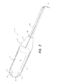
- Tampon applicator 10 houses and carries a tampon pledget 12 having a removal string 14. Tampon applicator 10 has a barrel 16 and a plunger 18 telescopically engageable with the barrel.
- the plunger 18 is adapted to eject the pledget 12 from the barrel 16 out of the ejection end 20 of the barrel into the vagina of a user.
- the barrel 16 has a central body 17 that is preferably tubular and is adapted to house and carry the pledget 12 therein.
- the barrel 16 has a forward or ejection end 20, and an opposite, rear or plunger- receiving end 32.
- the ejection end 20 of barrel 16 can be open or can have a dome shape.
- the ejection end 20 preferably has a hemispherical, dome-shaped tip 22.
- the tip 22 may include a plurality of petals 24, which are preferably formed by a plurality of slits 26.
- the petals 24 are flexible, enabling the pledget 12 to be ejected therethrough when the plunger 18 is pressed against the top of the pledget 12 within the barrel 16.
- the plunger-receiving end 32 of barrel 16 has a decreased or tapered width or diameter relative to central body 17 of the barrel, which serves as a transition between the body and the rearmost plunger edge 28.
- Receiving end 32 can have one or more substantially flattened surfaces, which form the fingergrip area.
- receiving end 32 has one or more pairs of diametrically opposed, substantially flattened surfaces.
- receiving end 32 has one pair of diametrically opposed, substantially flattened surfaces 30, which form a generally rectangular fingergrip area.
- receiving end 32 has two pairs of diametrically opposed, substantially flattened surfaces 30, which have a reduced diameter from central body 17 to plunger edge 28.
- the two pairs of substantially flattened surfaces form a generally square cross-section.
- Plunger 18 is also shown as having a generally square cross-section.
- receiving end 32 has three pairs of diametrically opposed, substantially flattened surfaces 30, which have a reduced diameter from central body 17 to plunger edge 28.
- the three pairs of diametrically opposed, substantially flattened surfaces 30 form a generally hexagonal cross-section, which results in superior gripping ability.
- Plunger 18 is also shown as having a generally hexagonal cross-section.
- applicator 10 of the present invention has three substantially flattened surfaces 30 formed on receiving end 32.
- the three substantially flattened surfaces have a reduced diameter from central body 17 to plunger edge 28 and form a generally triangular fingergrip area.
- Plunger 18 is also shown as having a generally triangular cross-section.
- Applicator 10 can be formed with any number of substantially flattened surfaces, pairs of diametrically opposed, substantially flattened surfaces, or any combinations thereof suitable for forming a fingergrip area on the receiving end of the barrel.
- receiving end 32 of applicator 10 has one pair of diametrically opposed, substantially flattened surfaces 30 and two angled shoulder surfaces 34.
- the shoulder surfaces 34 form a finger and/or thumb hold or grip.
- the angled shoulders 34 transcend from the barrel 16 to the flattened surfaces 30 and, thus, have a reduced diameter relative to the ejection end 20.
- the angled surface of the shoulders 34 can vary from almost 0° to almost 90° relative to the length of the barrel 16.
- the two substantially flattened surfaces 30 are generally decreasingly tapered from the angled shoulders 34 to the plunger edge 28.
- the angled shoulder surfaces 34 of the receiving end 32 provide an area on which the middle finger and thumb of a user may push off or rest on during the grasping of the applicator 10 and insertion of the applicator and pledget 12 into the vagina of a user. It should be understood that while Fig. 5 is depicted with two angled shoulders 34, applicator 10 could have at least two angled shoulders 34. The number of angled shoulders can correspond to the number of flattened surfaces formed on applicator 10.
- At least one, and more preferably a plurality, of gripping structures are disposed on the surfaces 30. While these alternative embodiments are discussed below with respect to Fig. 1 , they can be equally applied to the fingergrip area of Figs. 2 through 5 , 8 , and 9 .
- the gripping structures may be, for example, one or more embossments, protuberances other than ribs, slits, grooves, perforations, lances, abrasive media, high wet coefficient of friction material, pressure sensitive adhesive, or any combinations thereof.
- the gripping structures may be raised above surfaces 30, depressed below surfaces 30, constructed so as the top of the gripping structure aligns with the outer surface of surfaces 30, tilted towards or away from surfaces 30, or any combinations thereof.
- the gripping structures may be patterned or arranged in any configuration, and in any number suitable for creating an enhanced gripping area for a user's fingers.
- one embodiment of the at least one gripping structure of the fingergrip area of tampon applicator 10 of the present invention is shown having a plurality of circular shaped gripping structures 38 disposed on substantially flattened surfaces 30.
- These circular shaped gripping structures may be raised above surfaces 30, depressed below surfaces 30, through or virtually through surfaces 30, or a combination thereof.
- the gripping structures can be disposed in any suitable pattern or number.
- FIG. 7 another embodiment of the at least one gripping structure of tampon applicator 10 is depicted having a series of wavy gripping structures 40 disposed vertically across substantially flattened surfaces 30.
- the wavy gripping structures can also be raised above surfaces 30, depressed below surfaces 30, tilted towards and/or away from surfaces 30, or a combination thereof, and may be present in any suitable pattern or number.
- FIG. 8 another embodiment of the at least one gripping structure of tampon applicator 10 is depicted in which the surfaces 30 are formed with a concavity, thus providing an additional finger and/or thumb forming hold that conforms to a user's fingers.
- FIG. 9 another embodiment of the at least one gripping structure of tampon applicator 10 is depicted in which the surfaces 30 are formed with a convex outer surface, thus providing an additional finger and/or thumb forming hold.
- the gripping structures may be created on surfaces 30 by any method known in the art, such as, for example, molding, embossing, laser engraving, taping, gluing, shearing, die punching, or any combinations thereof.
- the receiving end 32 of the barrel 16 with a substantially flattened, and preferably also tapered, configuration and with at least one gripping structure, the receiving end serves as a superior grasping area, enabling the tampon user to easily and comfortably control and expel pledget 12 into the vagina.
- the receiving end 32 is shown in Figs. 1 through 5 as generally rectangular in cross-section to accommodate the flattened surfaces 30 thereof.
- Alternative cross-sectional shapes may be selected as long as such cross-sections accommodate the interior of surfaces 30 of the receiving end 32.
- the cross-sectional areas of either end of the receiving end 32 do not necessarily need to be the same.
- the examples shown in the figures have continued decreasing cross-sections from one end to the other.
- the cross-sections may reflect any concavities or convexities provided on the outer flattened surfaces 30 of the receiving end 32, to form an additional finger and/or thumb hold.
- the receiving end 32 is also constructed to receive and axially engage the plunger 18 through an opening 29 therein.
- the general cross-sectional configuration of the receiving end 32 and the plunger edge 28, in particular, are preferably similar or comparable to that of the plunger 18 to accommodate smooth axial engagement between the barrel 16 and the plunger 18.
- the corners of the rectangular cross section of the receiving end 32 have some radius of curvature, which reduces any untoward frictional contact of the plunger 18 with the outer surfaces of the receiving end 32 and to enhance the aesthetic appearance of the applicator 10.
- a curled lip 36 is provided on plunger 18, which provides a comfortable surface for resting the index finger in pushing the plunger forward to eject the pledget 12 from the barrel 16.
- the outer end of the plunger 18 may have other collar-like members or configurations such as an oval, circular cross-section or an arcuate finger rest that function in a like manner as the curled lip 36.
- the tampon pledget 12, and notably radially expanding tampon pledgets, are capable of exerting forces on the applicator barrel 16, namely an inside surface of the applicator barrel. Such forces make it difficult for a tampon user to expel the pledget 12 from the applicator barrel 16.
- the expansion of the pledget may be, by design, immediate upon release from a tampon applicator, i.e. the expansion occurs entirely or primarily in its dry state, without the need for moisture or menses, or it may be an unintentional effect due to aging. Because of these radial-expansion characteristics, an increased force is exerted on the inside wall or surface of the applicator barrel 16. It has been found that the force may be as high as several times that of a conventional pledget that requires menses or moisture to expand. As a result of this pressure, an increased expulsion force is required to expel the pledget 12 from the barrel 16. Expulsion forces in the magnitude of 2.5 pounds and greater have been measured for radially expanding tampon pledgets. The high pledget expulsion force requires an applicator with such a distinct fingergrip as provided by the present invention, in order to hold the applicator without the fear of deforming the applicator barrel 16 and further impeding expulsion of the radially expanding pledget 12.
- a woman can securely and comfortably grasp, control and position a tampon applicator 10 in accordance with the present invention, and expel a tampon pledget 12, especially a radially expanding pledget, housed therein, as a result of the fingergrip surface of the applicator 10, especially in conjunction with the at least one gripping structure formed on flattened surfaces 30.
- the gripping ability of a user can be further enhanced by forming diametrically opposed finger and/or thumb holds 34.
- the user's middle finger and thumb By placing the user's middle finger and thumb on the flattened surfaces 30 of the rear portion 32 of the barrel 16 and set against the angled shoulders 34 of the barrel 16, the user is able to easily maneuver, control and position a tampon within her vagina, and expel a pledget into her vagina, without any excess muscle tension or strain that could result in deformation of the barrel and/or plunger.
Landscapes
- Health & Medical Sciences (AREA)
- Epidemiology (AREA)
- Engineering & Computer Science (AREA)
- Biomedical Technology (AREA)
- Heart & Thoracic Surgery (AREA)
- Vascular Medicine (AREA)
- Life Sciences & Earth Sciences (AREA)
- Animal Behavior & Ethology (AREA)
- General Health & Medical Sciences (AREA)
- Public Health (AREA)
- Veterinary Medicine (AREA)
- Absorbent Articles And Supports Therefor (AREA)
Applications Claiming Priority (2)
| Application Number | Priority Date | Filing Date | Title |
|---|---|---|---|
| US09/894,042 US6890324B1 (en) | 2001-06-28 | 2001-06-28 | Tampon applicator |
| EP02780941A EP1401367A4 (fr) | 2001-06-28 | 2002-04-25 | Applicateur de tampon |
Related Parent Applications (2)
| Application Number | Title | Priority Date | Filing Date |
|---|---|---|---|
| EP02780941A Division EP1401367A4 (fr) | 2001-06-28 | 2002-04-25 | Applicateur de tampon |
| EP02780941.7 Division | 2002-04-25 |
Publications (2)
| Publication Number | Publication Date |
|---|---|
| EP2612640A2 true EP2612640A2 (fr) | 2013-07-10 |
| EP2612640A3 EP2612640A3 (fr) | 2014-06-11 |
Family
ID=25402514
Family Applications (3)
| Application Number | Title | Priority Date | Filing Date |
|---|---|---|---|
| EP02780941A Withdrawn EP1401367A4 (fr) | 2001-06-28 | 2002-04-25 | Applicateur de tampon |
| EP13156480.9A Withdrawn EP2612639A3 (fr) | 2001-06-28 | 2002-04-25 | Applicateur de tampon |
| EP13156481.7A Withdrawn EP2612640A3 (fr) | 2001-06-28 | 2002-04-25 | Applicateur de tampon |
Family Applications Before (2)
| Application Number | Title | Priority Date | Filing Date |
|---|---|---|---|
| EP02780941A Withdrawn EP1401367A4 (fr) | 2001-06-28 | 2002-04-25 | Applicateur de tampon |
| EP13156480.9A Withdrawn EP2612639A3 (fr) | 2001-06-28 | 2002-04-25 | Applicateur de tampon |
Country Status (5)
| Country | Link |
|---|---|
| US (2) | US6890324B1 (fr) |
| EP (3) | EP1401367A4 (fr) |
| JP (2) | JP2004532712A (fr) |
| CA (1) | CA2451773C (fr) |
| WO (1) | WO2003002048A1 (fr) |
Families Citing this family (37)
| Publication number | Priority date | Publication date | Assignee | Title |
|---|---|---|---|---|
| US6890324B1 (en) * | 2001-06-28 | 2005-05-10 | Playtex Products, Inc. | Tampon applicator |
| US7217252B2 (en) * | 2002-06-14 | 2007-05-15 | Mcneil-Ppc, Inc. | Applicator device for medicated materials |
| US7717873B2 (en) * | 2002-06-14 | 2010-05-18 | Mcneil-Ppc, Inc. | Applicator device for suppositories and the like |
| US20040010220A1 (en) * | 2002-06-21 | 2004-01-15 | Playtex Products, Inc. | Tampon applicator with improved fingergrip and method of making same |
| US7727208B2 (en) | 2002-09-12 | 2010-06-01 | Playtex Products, Inc. | Ergonomic tampon applicator |
| USD572362S1 (en) | 2003-04-04 | 2008-07-01 | Playtex Products, Inc. | Tampon applicator with finger grip |
| USD492033S1 (en) * | 2003-04-04 | 2004-06-22 | Playtex Products, Inc. | Tampon applicator assembly |
| US9192522B2 (en) | 2003-05-02 | 2015-11-24 | Eveready Battery Company, Inc. | Tampon assembly having shaped pledget |
| US7081110B2 (en) * | 2003-07-17 | 2006-07-25 | The Procter & Gamble Company | Applicator having an indented fingergrip with raised portions |
| US7294138B2 (en) * | 2004-06-28 | 2007-11-13 | Shippert Ronald D | Nose pack method and apparatus |
| US8372028B2 (en) | 2004-11-19 | 2013-02-12 | The Procter & Gamble Company | Tampon applicator |
| US20060167428A1 (en) * | 2005-01-21 | 2006-07-27 | Federica Denti | Tampon having indicators |
| US20070021710A1 (en) * | 2005-07-22 | 2007-01-25 | Bertulis Eugenia M | Tampon applicator having a multi-directional rim |
| US20070021708A1 (en) * | 2005-07-22 | 2007-01-25 | Bertulis Eugenia M | Tampon applicator having a multi-directional rim |
| US20070021709A1 (en) * | 2005-07-22 | 2007-01-25 | Bertulis Eugenia M | Tampon applicator having a multi-directional rim |
| US8308675B2 (en) * | 2006-03-31 | 2012-11-13 | Mcneil-Ppc, Inc. | Applicator device |
| CA2659887C (fr) * | 2006-08-04 | 2012-10-02 | Playtex Products, Inc. | Dispositif d'insertion d'un tampon permettant un meilleur positionnement du tampon et un meilleur controle |
| WO2008057581A1 (fr) | 2006-11-08 | 2008-05-15 | Playtex Products, Inc. | Compresse de tampon à meilleure prévention des fuites de contournement. |
| US20080228128A1 (en) * | 2007-03-14 | 2008-09-18 | Nancy Karapasha | Applicator having an intermittent gripping structure |
| US8075512B2 (en) | 2007-04-13 | 2011-12-13 | The Procter & Gamble Company | Applicator having an enhanced gripping region |
| JP5335773B2 (ja) | 2007-05-17 | 2013-11-06 | プレイテックス プロダクツ エルエルシー | 迂回漏れの防止強化のためのタンポンプレジェット |
| WO2009079607A1 (fr) * | 2007-12-18 | 2009-06-25 | Osel, Inc. | Applicateur permettant d'appliquer des formulations de poudre et utilisation de celles-ci |
| US20090192436A1 (en) * | 2008-01-24 | 2009-07-30 | Nancy Karapasha | Applicator having plunger with gripping elements |
| US20110144561A1 (en) * | 2008-03-26 | 2011-06-16 | Unicharm Corporation | Applicator for tampon |
| US20090281514A1 (en) | 2008-05-06 | 2009-11-12 | Playtex Products, Inc. | Tampon pledget with improved by-pass leakage protection |
| USD602588S1 (en) | 2008-07-15 | 2009-10-20 | Kimberly-Clark Worldwide, Inc. | Tampon applicator |
| US9339419B2 (en) * | 2008-07-15 | 2016-05-17 | Kimberly-Clark Worldwide, Inc. | Tampon applicator |
| US9107775B2 (en) | 2009-04-15 | 2015-08-18 | Eveready Battery Company, Inc. | Tampon pledget with improved by-pass leakage protection |
| US9233029B2 (en) * | 2009-06-22 | 2016-01-12 | The Procter & Gamble Company | Nesting tampon applicator |
| US8449491B2 (en) * | 2009-06-22 | 2013-05-28 | The Procter & Gamble Company | Applicator having extended gripping formations |
| USD620592S1 (en) | 2009-09-10 | 2010-07-27 | Kimberly-Clark Worldwide, Inc. | Tampon applicator |
| JP5791310B2 (ja) * | 2011-03-01 | 2015-10-07 | ユニ・チャーム株式会社 | タンポン用アプリケータ |
| GB201201645D0 (en) * | 2012-01-31 | 2012-03-14 | Ge Healthcare Ltd | Improvements in and relating to biological sample collection |
| US10111786B2 (en) | 2015-04-10 | 2018-10-30 | First Quality Hygienic, Inc. | Tampon applicator including beveled portion |
| GB2583896B (en) * | 2019-04-05 | 2023-08-16 | Calla Lily Personal Care Ltd | Drug delivery and administration device |
| US11565096B2 (en) | 2021-01-14 | 2023-01-31 | Herphoric, Inc. | Delivery system for a pharmaceutical, holistic or medicinal component |
| US20250221865A1 (en) * | 2022-04-29 | 2025-07-10 | Kimberly-Clark Worldwide, Inc. | Tampon Applicator Made With A Single Piece Barrel and Tampon Product Therefrom |
Citations (14)
| Publication number | Priority date | Publication date | Assignee | Title |
|---|---|---|---|---|
| US2489502A (en) | 1946-07-18 | 1949-11-29 | Int Cellucotton Products | Tampon applicator |
| US2587717A (en) | 1947-08-01 | 1952-03-04 | Int Cellucotton Products | Tampon applicator |
| US2922423A (en) | 1956-05-10 | 1960-01-26 | Kimberly Clark Co | Tampon ejector |
| US3575169A (en) | 1968-11-07 | 1971-04-20 | Joseph A Voss | Hygienic medium applicator |
| US3628533A (en) | 1970-04-20 | 1971-12-21 | Johnson & Johnson | Domed-tipped applicator for catamenial tampons |
| US3895634A (en) | 1973-10-18 | 1975-07-22 | Rapid American Corp | Tampon inserter |
| US4412833A (en) | 1981-05-29 | 1983-11-01 | Henkel Kommanditgesellschaft Auf Aktien | Tampon applicator |
| US4536178A (en) | 1983-11-10 | 1985-08-20 | International Playtex, Inc. | Tampon applicator |
| US4573963A (en) | 1983-10-17 | 1986-03-04 | Kimberly-Clark Corporation | Outer tampon tube with finger grip |
| US4573964A (en) | 1983-10-17 | 1986-03-04 | Kimberly-Clark Corporation | Outer tampon tube with recessed finger grip |
| US4891042A (en) | 1988-05-06 | 1990-01-02 | Playtex Family Products, Inc. | Portable tampon applicator |
| US5290501A (en) | 1992-05-20 | 1994-03-01 | Playtex Family Products Corporation | Method of forming cardboard tampon applicators having a dome-shaped forward tip |
| US5395308A (en) | 1993-09-24 | 1995-03-07 | Kimberly-Clark Corporation | Thermoplastic applicator exhibiting accelerated breakup when immersed in water |
| US6045526A (en) | 1999-02-05 | 2000-04-04 | Playtex Products, Inc. | Insertion device with laser engraved finger grip and method of making same |
Family Cites Families (57)
| Publication number | Priority date | Publication date | Assignee | Title |
|---|---|---|---|---|
| DE415565C (de) * | 1925-06-23 | Dupuis & Co Fa D | Einschleifvorrichtung fuer Absperrventile | |
| US3124134A (en) | 1964-03-10 | gardner | ||
| DE250663C (fr) * | ||||
| US1131349A (en) | 1914-05-25 | 1915-03-09 | American Tampon And Applicator Company | Applicator. |
| US2264586A (en) | 1937-06-24 | 1941-12-02 | Ross Frederick Alexander | Catamenial device |
| US2188923A (en) | 1937-10-20 | 1940-02-06 | Vera E Robinson | Tampon |
| US2248011A (en) * | 1941-01-10 | 1941-07-01 | Neuschaefer Franz | Container cover |
| US2476956A (en) | 1943-06-18 | 1949-07-26 | Personal Products Corp | Applicator |
| US2509241A (en) | 1947-05-10 | 1950-05-30 | Ortho Pharma Corp | Applicator |
| US2739593A (en) | 1954-02-25 | 1956-03-27 | Zonite Products Corp | Medicated vaginal tampons |
| US2934068A (en) | 1956-06-21 | 1960-04-26 | Personal Products Corp | Tow tampon |
| US2854978A (en) | 1956-07-24 | 1958-10-07 | Ortho Pharma Corp | Applicator |
| US3068867A (en) | 1959-01-02 | 1962-12-18 | Kimberly Clark Co | Cellulosic product |
| US3086527A (en) | 1959-03-18 | 1963-04-23 | David C Forrest | Medical applicator |
| US3059642A (en) | 1960-05-19 | 1962-10-23 | Personal Products Corp | Catamenial device |
| US3034508A (en) | 1960-10-19 | 1962-05-15 | Jr George S Nalle | Molded tampon applicators |
| US3090385A (en) | 1960-12-05 | 1963-05-21 | Johnson & Johnson | Tampon applicator |
| US3103929A (en) | 1961-01-12 | 1963-09-17 | Johnson & Johnson | Catamenial device |
| US3101713A (en) | 1961-02-23 | 1963-08-27 | Johnson & Johnson | Tampon applicator |
| US3148680A (en) | 1961-10-09 | 1964-09-15 | Johnson & Johnson | Tampon applicator |
| NL145138B (nl) | 1964-08-04 | Hahn Carl Dr Kg | Applicator met tampon. | |
| US3351060A (en) | 1965-05-17 | 1967-11-07 | Beltx Corp | Tampons |
| US3429312A (en) | 1966-11-21 | 1969-02-25 | Cleveland Container Corp | Tampon applicator |
| US3645263A (en) | 1969-08-21 | 1972-02-29 | Kimberly Clark Co | Locking arrangement for tube-type applicators for tampons and the like |
| US3674026A (en) | 1970-12-28 | 1972-07-04 | Kimberly Clark Co | Tampon insertion device |
| US3765417A (en) | 1971-02-24 | 1973-10-16 | Kimberly Clark Co | Arcuate tampon applicator |
| US3807399A (en) | 1971-12-09 | 1974-04-30 | Kimberly Clark Co | Tampon applicator |
| BE795933A (fr) | 1972-02-29 | 1973-08-27 | Hahn Carl Dr Gmbh | Applicateur de tampons |
| US3834389A (en) | 1972-11-28 | 1974-09-10 | Procter & Gamble | Textile tampon having a resilient foam core |
| US3831605A (en) | 1973-01-26 | 1974-08-27 | E Fournier | Multipurpose applicators |
| US3805786A (en) | 1973-03-28 | 1974-04-23 | Kimberly Clark Co | Tampon applicator combination |
| NZ185889A (en) | 1976-12-14 | 1979-10-25 | Unilever Ltd | Tampon applicator with longitudinal gripping ribs |
| USD250663S (en) | 1977-04-25 | 1978-12-26 | The Procter & Gamble Company | Tampon inserter |
| US4198978A (en) | 1977-09-29 | 1980-04-22 | The Gillette Company | Adjustable tampon inserter |
| US4182328A (en) | 1977-11-23 | 1980-01-08 | Population Research Incorporated | Dispensing instrument and method |
| US4424054A (en) | 1978-05-17 | 1984-01-03 | Kcdp Corporation | Fluid-expansible contraceptive tampon and applicator |
| JPS5563645A (en) | 1978-11-02 | 1980-05-13 | Kao Corp | Tampon |
| US4267881A (en) * | 1978-11-08 | 1981-05-19 | Byerly Cecil W | Heat storage sink |
| US4276881A (en) | 1979-10-22 | 1981-07-07 | Kimberly-Clark Corporation | Compact tampon applicator |
| US4361150A (en) | 1980-04-07 | 1982-11-30 | Voss Joseph A | Extruded plastic hygienic applicator |
| US4318405A (en) | 1980-07-24 | 1982-03-09 | Sneider Vincent R | Tampon and drug delivery device |
| US4479791A (en) | 1980-07-28 | 1984-10-30 | Tampax Incorporated | Tampon applicator |
| JPS6027303B2 (ja) | 1980-08-11 | 1985-06-28 | 花王株式会社 | タンポンのアプリケ−タ− |
| JPS5940008Y2 (ja) | 1980-11-20 | 1984-11-12 | ユニ・チヤ−ム株式会社 | 生理用タンポンの插入具 |
| JPH0240803B2 (ja) * | 1983-03-29 | 1990-09-13 | Tokyo Kyuko Dentetsu Kk | Kensetsusagyosochi |
| US4543086A (en) | 1984-06-01 | 1985-09-24 | Kimberly-Clark Corporation | Compact tampon applicator |
| JPS6154822A (ja) * | 1984-08-27 | 1986-03-19 | 株式会社日立製作所 | 発電所内母線切換制御方法 |
| GB2166656B (en) * | 1984-11-10 | 1988-06-29 | Kao Corp | Tampon applicator |
| JP2561922B2 (ja) * | 1986-04-23 | 1996-12-11 | キンバリ− クラ−ク コ−ポレ−シヨン | タンポン・アプリケ−タ |
| US4911687A (en) * | 1988-08-22 | 1990-03-27 | Playtex Family Products, Inc. | Compact tampon applicator with snap-action hinged panels |
| US5709652A (en) * | 1995-06-28 | 1998-01-20 | Mcneil-Ppc, Inc. | Tampon applicator tube having apertured finger grip |
| US5931803A (en) * | 1997-04-04 | 1999-08-03 | Playtex Products, Inc. | Epoxy coated tampon applicator having a pierce-through fingergrip |
| IL126111A0 (en) * | 1998-09-07 | 1999-05-09 | Medivice Systems Ltd | Tampon applicator |
| USD415565S (en) | 1999-01-04 | 1999-10-19 | The Procter & Gamble Company | Tampon applicator |
| US6322531B1 (en) * | 1999-06-25 | 2001-11-27 | Mcneil-Ppc, Inc. | Insertable applicator having a pivotal finger grip tab |
| US6368442B1 (en) * | 1999-06-25 | 2002-04-09 | Mcneil-Ppc, Inc. | Method of making applicators having improved finger grip features |
| US6890324B1 (en) * | 2001-06-28 | 2005-05-10 | Playtex Products, Inc. | Tampon applicator |
-
2001
- 2001-06-28 US US09/894,042 patent/US6890324B1/en not_active Expired - Fee Related
-
2002
- 2002-04-25 EP EP02780941A patent/EP1401367A4/fr not_active Withdrawn
- 2002-04-25 EP EP13156480.9A patent/EP2612639A3/fr not_active Withdrawn
- 2002-04-25 EP EP13156481.7A patent/EP2612640A3/fr not_active Withdrawn
- 2002-04-25 JP JP2003508291A patent/JP2004532712A/ja active Pending
- 2002-04-25 CA CA002451773A patent/CA2451773C/fr not_active Expired - Fee Related
- 2002-04-25 WO PCT/US2002/013153 patent/WO2003002048A1/fr not_active Ceased
-
2004
- 2004-11-18 US US10/991,938 patent/US20050070839A1/en not_active Abandoned
-
2008
- 2008-02-28 JP JP2008048346A patent/JP4865748B2/ja not_active Expired - Fee Related
Patent Citations (14)
| Publication number | Priority date | Publication date | Assignee | Title |
|---|---|---|---|---|
| US2489502A (en) | 1946-07-18 | 1949-11-29 | Int Cellucotton Products | Tampon applicator |
| US2587717A (en) | 1947-08-01 | 1952-03-04 | Int Cellucotton Products | Tampon applicator |
| US2922423A (en) | 1956-05-10 | 1960-01-26 | Kimberly Clark Co | Tampon ejector |
| US3575169A (en) | 1968-11-07 | 1971-04-20 | Joseph A Voss | Hygienic medium applicator |
| US3628533A (en) | 1970-04-20 | 1971-12-21 | Johnson & Johnson | Domed-tipped applicator for catamenial tampons |
| US3895634A (en) | 1973-10-18 | 1975-07-22 | Rapid American Corp | Tampon inserter |
| US4412833A (en) | 1981-05-29 | 1983-11-01 | Henkel Kommanditgesellschaft Auf Aktien | Tampon applicator |
| US4573963A (en) | 1983-10-17 | 1986-03-04 | Kimberly-Clark Corporation | Outer tampon tube with finger grip |
| US4573964A (en) | 1983-10-17 | 1986-03-04 | Kimberly-Clark Corporation | Outer tampon tube with recessed finger grip |
| US4536178A (en) | 1983-11-10 | 1985-08-20 | International Playtex, Inc. | Tampon applicator |
| US4891042A (en) | 1988-05-06 | 1990-01-02 | Playtex Family Products, Inc. | Portable tampon applicator |
| US5290501A (en) | 1992-05-20 | 1994-03-01 | Playtex Family Products Corporation | Method of forming cardboard tampon applicators having a dome-shaped forward tip |
| US5395308A (en) | 1993-09-24 | 1995-03-07 | Kimberly-Clark Corporation | Thermoplastic applicator exhibiting accelerated breakup when immersed in water |
| US6045526A (en) | 1999-02-05 | 2000-04-04 | Playtex Products, Inc. | Insertion device with laser engraved finger grip and method of making same |
Also Published As
| Publication number | Publication date |
|---|---|
| WO2003002048A1 (fr) | 2003-01-09 |
| CA2451773C (fr) | 2010-01-12 |
| EP1401367A1 (fr) | 2004-03-31 |
| EP2612640A3 (fr) | 2014-06-11 |
| WO2003002048B1 (fr) | 2003-04-03 |
| JP4865748B2 (ja) | 2012-02-01 |
| EP1401367A4 (fr) | 2009-09-09 |
| US20050070839A1 (en) | 2005-03-31 |
| CA2451773A1 (fr) | 2003-01-09 |
| JP2008132363A (ja) | 2008-06-12 |
| JP2004532712A (ja) | 2004-10-28 |
| US6890324B1 (en) | 2005-05-10 |
| EP2612639A3 (fr) | 2014-06-11 |
| EP2612639A2 (fr) | 2013-07-10 |
Similar Documents
| Publication | Publication Date | Title |
|---|---|---|
| US6890324B1 (en) | Tampon applicator | |
| EP1551347B1 (fr) | Applicateur de tampon hygienique muni d'un dispositif de prise avec les doigts ameliore, et procede de fabrication de l'applicateur | |
| CA2461130C (fr) | Applicateur de tampon a organe de prehension digitale ameliore | |
| CA2498508C (fr) | Applicateur ergonomique de tampon | |
| US4536178A (en) | Tampon applicator | |
| US10925705B2 (en) | Pessary with applicator | |
| US8372027B2 (en) | Tampon applicator assembly | |
| US20090192436A1 (en) | Applicator having plunger with gripping elements | |
| CA2521246C (fr) | Ensemble applicateur pour tampon ameliore | |
| EP1832265A2 (fr) | Applicateur de tampon avec empreintes améliorées et son procédé de fabrication |
Legal Events
| Date | Code | Title | Description |
|---|---|---|---|
| PUAI | Public reference made under article 153(3) epc to a published international application that has entered the european phase |
Free format text: ORIGINAL CODE: 0009012 |
|
| AC | Divisional application: reference to earlier application |
Ref document number: 1401367 Country of ref document: EP Kind code of ref document: P |
|
| AK | Designated contracting states |
Kind code of ref document: A2 Designated state(s): AT BE CH CY DE DK ES FI FR GB GR IE IT LI LU MC NL PT SE TR |
|
| PUAL | Search report despatched |
Free format text: ORIGINAL CODE: 0009013 |
|
| RIC1 | Information provided on ipc code assigned before grant |
Ipc: A61F 13/20 20060101AFI20140430BHEP |
|
| AK | Designated contracting states |
Kind code of ref document: A3 Designated state(s): AT BE CH CY DE DK ES FI FR GB GR IE IT LI LU MC NL PT SE TR |
|
| STAA | Information on the status of an ep patent application or granted ep patent |
Free format text: STATUS: THE APPLICATION HAS BEEN WITHDRAWN |
|
| 18W | Application withdrawn |
Effective date: 20140704 |