EP2612700A1 - Elektrisch beheizter katalysator - Google Patents
Elektrisch beheizter katalysator Download PDFInfo
- Publication number
- EP2612700A1 EP2612700A1 EP10856676.1A EP10856676A EP2612700A1 EP 2612700 A1 EP2612700 A1 EP 2612700A1 EP 10856676 A EP10856676 A EP 10856676A EP 2612700 A1 EP2612700 A1 EP 2612700A1
- Authority
- EP
- European Patent Office
- Prior art keywords
- electrode chamber
- case
- generation element
- heat generation
- exhaust gas
- Prior art date
- Legal status (The legal status is an assumption and is not a legal conclusion. Google has not performed a legal analysis and makes no representation as to the accuracy of the status listed.)
- Granted
Links
Images

Classifications
-
- F—MECHANICAL ENGINEERING; LIGHTING; HEATING; WEAPONS; BLASTING
- F01—MACHINES OR ENGINES IN GENERAL; ENGINE PLANTS IN GENERAL; STEAM ENGINES
- F01N—GAS-FLOW SILENCERS OR EXHAUST APPARATUS FOR MACHINES OR ENGINES IN GENERAL; GAS-FLOW SILENCERS OR EXHAUST APPARATUS FOR INTERNAL-COMBUSTION ENGINES
- F01N3/00—Exhaust or silencing apparatus having means for purifying, rendering innocuous, or otherwise treating exhaust
- F01N3/08—Exhaust or silencing apparatus having means for purifying, rendering innocuous, or otherwise treating exhaust for rendering innocuous
- F01N3/10—Exhaust or silencing apparatus having means for purifying, rendering innocuous, or otherwise treating exhaust for rendering innocuous by thermal or catalytic conversion of noxious components of exhaust
- F01N3/18—Exhaust or silencing apparatus having means for purifying, rendering innocuous, or otherwise treating exhaust for rendering innocuous by thermal or catalytic conversion of noxious components of exhaust characterised by methods of operation; Control
- F01N3/20—Exhaust or silencing apparatus having means for purifying, rendering innocuous, or otherwise treating exhaust for rendering innocuous by thermal or catalytic conversion of noxious components of exhaust characterised by methods of operation; Control specially adapted for catalytic conversion
- F01N3/2006—Periodically heating or cooling catalytic reactors, e.g. at cold starting or overheating
- F01N3/2013—Periodically heating or cooling catalytic reactors, e.g. at cold starting or overheating using electric or magnetic heating means
- F01N3/2026—Periodically heating or cooling catalytic reactors, e.g. at cold starting or overheating using electric or magnetic heating means directly electrifying the catalyst substrate, i.e. heating the electrically conductive catalyst substrate by joule effect
-
- F—MECHANICAL ENGINEERING; LIGHTING; HEATING; WEAPONS; BLASTING
- F01—MACHINES OR ENGINES IN GENERAL; ENGINE PLANTS IN GENERAL; STEAM ENGINES
- F01N—GAS-FLOW SILENCERS OR EXHAUST APPARATUS FOR MACHINES OR ENGINES IN GENERAL; GAS-FLOW SILENCERS OR EXHAUST APPARATUS FOR INTERNAL-COMBUSTION ENGINES
- F01N3/00—Exhaust or silencing apparatus having means for purifying, rendering innocuous, or otherwise treating exhaust
- F01N3/08—Exhaust or silencing apparatus having means for purifying, rendering innocuous, or otherwise treating exhaust for rendering innocuous
- F01N3/10—Exhaust or silencing apparatus having means for purifying, rendering innocuous, or otherwise treating exhaust for rendering innocuous by thermal or catalytic conversion of noxious components of exhaust
- F01N3/18—Exhaust or silencing apparatus having means for purifying, rendering innocuous, or otherwise treating exhaust for rendering innocuous by thermal or catalytic conversion of noxious components of exhaust characterised by methods of operation; Control
- F01N3/20—Exhaust or silencing apparatus having means for purifying, rendering innocuous, or otherwise treating exhaust for rendering innocuous by thermal or catalytic conversion of noxious components of exhaust characterised by methods of operation; Control specially adapted for catalytic conversion
- F01N3/2006—Periodically heating or cooling catalytic reactors, e.g. at cold starting or overheating
- F01N3/2013—Periodically heating or cooling catalytic reactors, e.g. at cold starting or overheating using electric or magnetic heating means
-
- F—MECHANICAL ENGINEERING; LIGHTING; HEATING; WEAPONS; BLASTING
- F01—MACHINES OR ENGINES IN GENERAL; ENGINE PLANTS IN GENERAL; STEAM ENGINES
- F01N—GAS-FLOW SILENCERS OR EXHAUST APPARATUS FOR MACHINES OR ENGINES IN GENERAL; GAS-FLOW SILENCERS OR EXHAUST APPARATUS FOR INTERNAL-COMBUSTION ENGINES
- F01N3/00—Exhaust or silencing apparatus having means for purifying, rendering innocuous, or otherwise treating exhaust
- F01N3/08—Exhaust or silencing apparatus having means for purifying, rendering innocuous, or otherwise treating exhaust for rendering innocuous
- F01N3/10—Exhaust or silencing apparatus having means for purifying, rendering innocuous, or otherwise treating exhaust for rendering innocuous by thermal or catalytic conversion of noxious components of exhaust
- F01N3/24—Exhaust or silencing apparatus having means for purifying, rendering innocuous, or otherwise treating exhaust for rendering innocuous by thermal or catalytic conversion of noxious components of exhaust characterised by constructional aspects of converting apparatus
- F01N3/28—Construction of catalytic reactors
- F01N3/2839—Arrangements for mounting catalyst support in housing, e.g. with means for compensating thermal expansion or vibration
- F01N3/2853—Arrangements for mounting catalyst support in housing, e.g. with means for compensating thermal expansion or vibration using mats or gaskets between catalyst body and housing
- F01N3/2871—Arrangements for mounting catalyst support in housing, e.g. with means for compensating thermal expansion or vibration using mats or gaskets between catalyst body and housing the mats or gaskets having an additional, e.g. non-insulating or non-cushioning layer, a metal foil or an adhesive layer
-
- Y—GENERAL TAGGING OF NEW TECHNOLOGICAL DEVELOPMENTS; GENERAL TAGGING OF CROSS-SECTIONAL TECHNOLOGIES SPANNING OVER SEVERAL SECTIONS OF THE IPC; TECHNICAL SUBJECTS COVERED BY FORMER USPC CROSS-REFERENCE ART COLLECTIONS [XRACs] AND DIGESTS
- Y02—TECHNOLOGIES OR APPLICATIONS FOR MITIGATION OR ADAPTATION AGAINST CLIMATE CHANGE
- Y02T—CLIMATE CHANGE MITIGATION TECHNOLOGIES RELATED TO TRANSPORTATION
- Y02T10/00—Road transport of goods or passengers
- Y02T10/10—Internal combustion engine [ICE] based vehicles
- Y02T10/12—Improving ICE efficiencies
Definitions
- the present invention relates to an electrically heated catalyst that is arranged in an exhaust passage of an internal combustion engine.
- an electrically heated catalyst (hereinafter referred to as an EHC) in which a catalyst is heated by means of a heat generation element which generates heat by electrical energization thereof.
- an insulating member which serves to insulate electricity, is arranged between the heat generation element which generates heat by electrical energization thereof, and a case in which the heat generation element is received.
- a technique in which in an EHC, a mat of an insulating material is arranged between a carrier which is electrically energized to generate heat and a case in which the carrier is received Due to the arrangement of such an insulating member, it is possible to suppress the heat generation element and the case from being short-circuited to each other.
- Patent Document 1 Japanese patent application laid-open No. H05-269387
- an electrode chamber which is a space for passing or inserting electrodes connected to the heat generation element.
- the insulating member and the heat generation element together constitute a wall surface of the electrode chamber.
- the exhaust gas flowing in an exhaust pipe permeates into the insulating member and the heat generation element.
- the exhaust gas which has passed through or along the insulating member or the outer peripheral wall of the heat generation element, comes.
- Moisture is contained in the exhaust gas, and hence, when the exhaust gas comes into the electrode chamber, condensed water may be generated in the electrode chamber due to the condensation of the moisture in the exhaust gas.
- condensed water may be generated due to the condensation of the moisture in the exhaust gas on a wall surface of the exhaust pipe.
- the condensed water is generated inside the exhaust pipe, it is forced by the exhaust gas to flow along the inner wall surface of the exhaust pipe. Then, at the time when the condensed water reaches the EHC, it permeates into the insulating member and the heat generation element.
- the condensed water permeates into the insulating member and the heat generation element, the condensed water having passed through them as well as water vapor generated by the evaporation of the condensed water in the insides of the insulating member and the heat generation element may come into the electrode chamber.
- the electrode chamber is a space surrounded by the heat generation element, the insulating member and the like, inside the case. For that reason, the condensed water or water vapor, which has been generated in the electrode chamber or permeated into the electrode chamber, stays easily in the electrode chamber. When the humidity in the electrode chamber rises excessively with the water vapor, there is a fear that the insulation resistance between the electrodes in the electrode chamber and the case may decrease to a large extent. In addition, when the condensed water exists in the electrode chamber, there is also another fear that the electrodes and the case may be short-circuited by the condensed water itself.
- the present invention has been made in view of the above problems, and has for its object to suppress a decrease in the insulation resistance between electrodes and a case in an EHC.
- the present invention is provided with a communication passage for making communication between an electrode chamber and an exhaust passage.
- an EHC according to the present invention is an electrically heated catalyst which is arranged in an exhaust passage of an internal combustion engine, said catalyst comprising:
- the provision of the communication passage permits the electrode chamber to be ventilated. For that reason, it is possible to suppress the humidity in the electrode chamber from rising. In addition, it is possible to suppress condensed water from staying in the electrode chamber. Thus, it is possible to suppress a decrease in the insulation resistance between the electrodes and the case in the electrode chamber, which would otherwise result from the condensed water or water vapor therein.
- the communication passage may be constructed so as to make communication between a portion of the exhaust passage at the downstream side of the electrically heated catalyst and said electrode chamber.
- the exhaust gas introduced into the electrode chamber through the communication passage can be made an exhaust gas which has been purified by the EHC. As a result of this, it is possible to suppress the corrosion of the electrodes and the contamination of the electrode chamber.
- the communication passage may be arranged in plurality. According to this, it is possible to facilitate the ventilation of the electrode chamber to a further extent.
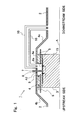
- Fig. 1 is a view showing the schematic construction of an electrically heated catalyst (EHC) according to this first embodiment of the present invention.
- the EHC 1 according to this embodiment is arranged in an exhaust pipe of an internal combustion engine mounted on a vehicle.
- the internal combustion engine may be a diesel engine, or may be a gasoline engine.
- the EHC 1 according to this embodiment can also be used in a vehicle which adopts a hybrid system equipped with an electric motor.
- Fig. 1 is a cross sectional view which shows the EHC 1 cut in a longitudinal direction thereof along a central axis A of an exhaust pipe 2 of the internal combustion engine.
- the shape of the EHC 1 is in line symmetry with respect to the central axis A, and hence, in Fig. 1 , only an upper part of the EHC 1 is shown for the sake of convenience.
- the EHC 1 is provided with a catalyst carrier 3, a case 4, a mat 5, an inner pipe 6, electrodes 7, and communication passages 10.
- the catalyst carrier 3 is formed in the shape of a circular cylinder, and is arranged in such a manner that a central axis thereof is in alignment with the central axis A of the exhaust pipe 2.
- An exhaust gas purification catalyst 15 is carried or supported by the catalyst carrier 3.
- the catalyst carrier 3 is formed of a material which, when electrically energized, becomes an electric resistance to generate heat.
- a material for the catalyst carrier 3 there can be exemplified SiC.
- the catalyst carrier 3 has a plurality of passages which extend in a direction in which an exhaust gas flows (i.e., the direction of the central axis A), and which have a cross section of honeycomb shape vertical to the direction in which the exhaust gas flows. The exhaust gas flows through these passages.
- the cross sectional shape of the catalyst carrier 3 in the direction orthogonal to the central axis A may be elliptical, etc.
- the central axis A is a central axis common to the exhaust pipe 2, the catalyst carrier 3, the inner pipe 6, and the case 4.
- the catalyst carrier 3 is received in the case 4.
- An electrode chamber 9 is formed in the case 4.
- One pair of electrodes 7 (only one electrode being illustrated in Fig. 1 ) are connected to the catalyst carrier 3 through the electrode chamber 9. Electricity is supplied to the electrodes 7 from a battery (not shown). When electricity is supplied to the electrode 7, the catalyst carrier 3 is electrically energized. When the catalyst carrier 3 generates heat by electrical energization thereof, the exhaust gas purification catalyst 15 supported by the catalyst carrier 3 is heated, so that the activation thereof is facilitated.
- the case 4 is formed of metal. As a material which forms the case 4, there can be exemplified a stainless steel material.
- the case 4 has a receiving portion 4a which is constructed to include a curved surface parallel to the central axis A, and tapered portions 4b, 4c which serve to connect the receiving portion 4a and the exhaust pipe 2 with each other at the upstream side and the downstream side, respectively, of the receiving portion 4a.
- the receiving portion 4a has a channel cross section which is larger than that of the exhaust pipe 2, and the catalyst carrier 3, the mat 5, and the inner pipe 6 are received in the inside of the receiving portion 4a.
- the tapered portions 4b, 4c each take a tapered shape of which the channel cross section decreases in accordance with the increasing distance thereof from the receiving portion 4a.
- the mat 5 is inserted between an inner wall surface of the receiving portion 4a of the case 4, and an outer peripheral surface of the catalyst carrier 3.
- the catalyst carrier 3 is supported by the mat 5.
- the inner pipe 6 is inserted in the mat 5.
- the mat 5 is divided into a portion at the side of the case 4 and a portion at the side of the catalyst carrier 3 by means of the inner pipe 6.
- the mat 5 is formed of an electrically insulating material.
- a material which forms the mat 5 there can be exemplified a ceramic fiber which includes alumina as a main component.
- the mat 5 is wound around the outer peripheral surface of the catalyst carrier 3 and an outer peripheral surface of the inner pipe 6. Due to the insertion of the mat 5 between the catalyst carrier 3 and the case 4, it is possible to suppress electricity from flowing into the case 4 at the time when the catalyst carrier 3 is electrically energized.
- the inner pipe 6 is formed of an electrically insulating material.
- Alumina can be exemplified as a material which forms the inner pipe 6.
- the inner pipe 6 is formed into a tubular shape with the central axis A being located as a center thereof. As shown in Fig. 1 , the inner pipe 6 has a length in the direction of the central axis A longer than that of the mat 5. As a result, the inner pipe 6 has an upstream side end and a downstream side end thereof protruded from an upstream side end face and a downstream side end face of the mat 5, respectively.
- the case 4 and the inner pipe 6 have through holes 4d, 6a opened therein so as to allow the electrodes 7 to pass them, respectively.
- the mat 5 has a space formed therein so as to allow the electrodes 7 to pass therethrough.
- the electrode chamber 9 is formed by such a space which is located between an inner wall surface of the case 4 and the outer peripheral surface of the catalyst carrier 3, and which has a side wall surface thereof formed by the mat 5.
- Support members 8 which serve to support the electrodes 7, respectively, are arranged in the through holes 4d which are opened in the case 4.
- the support members 8 are formed of an electrically insulating material, and are fitted with no gap between the case 4 and the electrodes 7.
- the EHC 1 is provided with the communication passages 10 for placing the electrode chamber 9 and the exhaust pipe 2 in fluid communication with each other.
- Each of the two communication passages 10 has one end thereof connected to the electrode chamber 9, and the other end thereof connected to the exhaust pipe 2 at a location downstream of the EHC 1.
- any of the communication passages is connected to the exhaust pipe 2 at a location downstream of the EHC 1.
- An electrode chamber 9 may be formed over the entire circumference of a side surface of the catalyst carrier 3.
- the plus side electrode and the minus side electrode are connected to the catalyst carrier 3 through the single electrode chamber.
- two communication passages should be connected to this single electrode chamber.
- the catalyst carrier 3 corresponds to a heat generation element according to the present invention.
- the heat generation element according to the present invention is not limited to a carrier which supports a catalyst, but instead the heat generation element may be a structure which is arranged at the upstream side of a catalyst, for example.
- the case 4 corresponds to a case according to the present invention
- the mat 5 corresponds to an insulating member according to the present invention.
- the communication passages 10 correspond to communication passages according to the present invention.
- arrows indicate flows of exhaust gas, condensed water, and water vapor which has been generated due to the evaporation of the condensed water.
- the exhaust gas flowing in the exhaust pipe 2 permeates into the mat 5 and the catalyst carrier 3.
- the moisture in the exhaust gas may condense, thus generating condensed water inside the electrode chamber 9.
- the condensed water when condensed water is generated in the exhaust pipe 2 and this condensed water permeates into the mat 5 or the catalyst carrier 3, the condensed water stays inside the mat 5 or the catalyst carrier 3. Then, when the amount of the condensed water, which has stayed inside the mat 5 or the catalyst carrier 3, increases, the condensed water may come into the electrode chamber 9. Also, when the temperature of the exhaust gas rises, the condensed water, which has stayed inside the mat 5 or the catalyst carrier 3, may evaporate, so that the condensed water may come into the electrode chamber 9 in a state of water vapor.
- the electrode chamber 9 is a closed space that is surrounded by the inner wall surface of the case 4, the side surface of the catalyst carrier 3 and the mat 5, the condensed water or water vapor, which has been generated in the electrode chamber 9 or has come into the electrode chamber 9, is apt to stay in this electrode chamber 9. Then, when the condensed water exists in the electrode chamber 9, there is a fear that the electrodes 7 and the case 4 may be short-circuited by the condensed water.
- FIG. 2 is a view showing the temporal changes of the humidity in the electrode chamber 9 and the insulation resistance between the electrodes 7 and the case 4 in the electrode chamber 9 from the time of starting of the internal combustion engine.
- the axis of ordinate represents the humidity he in the electrode chamber 9, or the insulation resistance Re between the electrodes 7 and the case 4 in the electrode chamber 9, and the axis of abscissa represents time t.
- solid lines L1, L2 indicate the change over time of the humidity he in the electrode chamber 9.
- a broken line L1' indicates the change over time of the insulation resistance Re between the electrodes 7 and the case 4 in the electrode chamber 9 at the time when the humidity he in the electrode chamber 9 changes as shown by the solid line L1.
- a broken line L2' indicates the change over time of the insulation resistance Re between the electrodes 7 and the case 4 in the electrode chamber 9 at the time when the humidity he in the electrode chamber 9 changes as shown by the solid line L2.
- the insulation resistance Re between the electrodes 7 and the case 4 will rise quickly in accordance with the drop in the humidity he in the electrode chamber 9, and will be maintained at a high level.
- the insulation resistance Re between the electrodes 7 and the case 4 drops to a large extent, as shown by the broken line L1'.
- the communication passages 10 are provided in the EHC 1 in order to ventilate the electrode chamber 9.
- the other ends of the communication passages 10 are connected to the exhaust pipe 2. Therefore, it is possible to carry out ventilation between the electrode chamber 9 and the exhaust pipe 2 by way of the communication passages 10. According to this, it is possible to suppress the water vapor from staying in the electrode chamber 9. As a result, it is possible to suppress the humidity in the electrode chamber 9 from rising, and the condensed water from staying in the electrode chamber 9.
- connection positions of the other ends of the communication passages 10 are not necessarily limited to a portion in the exhaust pipe 2 at the downstream side of the EHC 1.
- the other ends of the communication passages may be connected to a portion in the exhaust pipe 2 at the upstream side of the EHC 1, or connected to an exhaust manifold, etc., to which the exhaust pipe 2 is connected.
- the exhaust gas introduced into the electrode chamber 9 through the communication passages 10 can be made an exhaust gas which has been purified by the EHC 1.
- the corrosion of the electrodes 7 by acidic components contained in the exhaust gas as well as the contamination of the electrode chamber 9 by organic components contained in the exhaust gas can be suppressed.
- the number of communication passages does not necessarily need to be two, but three or more communication passages may be provided. Also, the number of communication passages may be one. Even if the number of communication passages is one, the coming in and out of gas occurs between the inside of the electrode chamber 9 and the inside of the exhaust pipe 2 due to a pressure difference between the inside of the exhaust pipe 2 and the inside of the electrode chamber 9 generated by the pulsation of the exhaust gas in the exhaust pipe 2, and/or a difference in temperature therebetween, whereby the electrode chamber 9 can be ventilated.
- the provision of the plurality of communication passages 10 can serve to facilitate the ventilation of the electrode chamber 9 to a further extent.
- exhaust gas purification catalysts may be arranged in the communication passages 10, respectively. According to this, the exhaust gas introduced into the electrode chamber 9 through the communication passages 10 can be purified to a further extent. It is preferable that the exhaust gas purification catalysts, which are arranged in the communication passages 10, respectively, be able to reduce the acidic components contained in the exhaust gas, and be able to oxidize the organic components contained in the exhaust gas.
- Particulate filters which serve to trap the particulate matter in the exhaust gas, may also be arranged in the communication passages 10, respectively. According to this, it is possible to suppress the particulate matter from coming into the electrode chamber 9 through the communication passages 10.
- Moisture trapping members which serve to absorb or adsorb the moisture in the exhaust gas, may be arranged in the communication passages 10, respectively. According to this, it is possible to suppress the moisture from coming into the electrode chamber 9 through the communication passages 10.
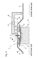
- Fig. 3 is a view showing the schematic construction of an EHC according to this second embodiment.
- communication control valves 11, which serve to open or block two communication passages 10, are arranged in the two communication passages 10, respectively.
- the communication control valves 11 are electrically connected to an electronic control unit (ECU: not shown).
- the communication control valves 11 are controlled by the ECU.
- the communication control valves 11 are closed, the communication passages 10 are opened, whereas when the communication control valves 11 are closed, the communication passages 10 are blocked or closed.
- the construction other than the communication control valves 11 is the same as that of the EHC according to the first embodiment.
- Moisture is also contained in the exhaust gas which is introduced into the electrode chamber 9 from the exhaust pipe 2 through the communication passages 10. Accordingly, in this embodiment, when there is a high possibility that the moisture in the exhaust gas introduced from the exhaust pipe 2 into the electrode chamber 9 through the communication passages 10 will condense in the electrode chamber 9, the communication passages 10 are blocked by the communication control valves 11, respectively, so that the introduction of the exhaust gas is inhibited. Then, when there is a low possibility that the moisture in the exhaust gas introduced from the exhaust pipe 2 into the electrode chamber 9 through the communication passages 10 will condense in the electrode chamber 9, the communication passages 10 are opened by the communication control valves 11, respectively, so that the ventilation of the electrode chamber 9 is carried out.
- the temperature in the electrode chamber 9 is low until the warming-up of the internal combustion engine is completed, so the moisture in the exhaust gas is liable to condense in the electrode chamber 9. Accordingly, the communication control valves 11 are closed until the warming-up of the internal combustion engine is completed, and the communication control valves 11 are opened after the completion of the warming-up.
- the generation of condensed water in accordance with the ventilation of the electrode chamber 9 can be suppressed.
- a temperature sensor which serves to detect the temperature in the electrode chamber 9
- a moisture concentration sensor which serves to detect the moisture concentration of the exhaust gas introduced into the electrode chamber 9 through the communication passages 10 may be arranged in one or each of the communication passages 10, or in the vicinity of connection portions of the communication passages 10 in the exhaust pipe 2. In cases where these sensors are provided, a determination may be made, based on the temperature in the electrode chamber 9 detected by the temperature sensor and the moisture concentration of the exhaust gas detected by the moisture concentration sensor, as to whether the possibility that the moisture in the exhaust gas introduced through the communication passages 10 will condense in the electrode chamber 9 is high.
- the moisture concentration of the exhaust gas introduced into the electrode chamber 9 through the communication passages 10 can be estimated even if any moisture concentration sensor is not provided.
- an amount of moisture generated by the combustion of an air-fuel mixture is calculated based on the air fuel ratio of the air-fuel mixture which is supplied to the internal combustion engine for combustion therein, and the moisture concentration of the exhaust gas discharged from the internal combustion engine is calculated based on the amount of moisture thus calculated and the flow rate of the exhaust gas.
- the moisture concentration of the exhaust gas introduced into the electrode chamber 9 through the communication passages 10 is calculated based on the moisture concentration of the exhaust gas discharged from the internal combustion engine, and the temperature and pressure of the exhaust gas in the vicinity of the connection portions of the communication passages 10 in the exhaust pipe 2.
Landscapes
- Chemical & Material Sciences (AREA)
- Engineering & Computer Science (AREA)
- Chemical Kinetics & Catalysis (AREA)
- Health & Medical Sciences (AREA)
- Toxicology (AREA)
- Combustion & Propulsion (AREA)
- Mechanical Engineering (AREA)
- General Engineering & Computer Science (AREA)
- Exhaust Gas After Treatment (AREA)
- Catalysts (AREA)
Applications Claiming Priority (1)
| Application Number | Priority Date | Filing Date | Title |
|---|---|---|---|
| PCT/JP2010/064804 WO2012029124A1 (ja) | 2010-08-31 | 2010-08-31 | 電気加熱式触媒 |
Publications (3)
| Publication Number | Publication Date |
|---|---|
| EP2612700A1 true EP2612700A1 (de) | 2013-07-10 |
| EP2612700A4 EP2612700A4 (de) | 2014-07-09 |
| EP2612700B1 EP2612700B1 (de) | 2015-11-25 |
Family
ID=45772262
Family Applications (1)
| Application Number | Title | Priority Date | Filing Date |
|---|---|---|---|
| EP10856676.1A Not-in-force EP2612700B1 (de) | 2010-08-31 | 2010-08-31 | Elektrisch beheizter katalysator |
Country Status (5)
| Country | Link |
|---|---|
| US (1) | US9121322B2 (de) |
| EP (1) | EP2612700B1 (de) |
| JP (1) | JP5387777B2 (de) |
| CN (1) | CN103153436B (de) |
| WO (1) | WO2012029124A1 (de) |
Families Citing this family (5)
| Publication number | Priority date | Publication date | Assignee | Title |
|---|---|---|---|---|
| CN103038470B (zh) * | 2010-08-24 | 2016-07-06 | 丰田自动车株式会社 | 电加热式催化剂 |
| JP6826537B2 (ja) * | 2015-11-16 | 2021-02-03 | 日本碍子株式会社 | ハニカム型加熱装置及びその使用方法 |
| JP6838542B2 (ja) * | 2017-10-12 | 2021-03-03 | トヨタ自動車株式会社 | 触媒装置 |
| JP2019074033A (ja) * | 2017-10-17 | 2019-05-16 | トヨタ自動車株式会社 | 電気加熱式触媒 |
| DE102018127074A1 (de) * | 2018-10-30 | 2020-04-30 | Faurecia Emissions Control Technologies, Germany Gmbh | Katalysatorkörper, elektrisch beheizbarer Katalysator, Kraftfahrzeug mit Katalysator und Verfahren zur Herstellung eines Katalysators |
Family Cites Families (25)
| Publication number | Priority date | Publication date | Assignee | Title |
|---|---|---|---|---|
| US4976929A (en) | 1988-05-20 | 1990-12-11 | W. R. Grace & Co.-Conn. | Electrically heated catalytic converter |
| JP2818473B2 (ja) * | 1990-06-29 | 1998-10-30 | 日本碍子株式会社 | 自動車排ガス浄化用触媒コンバーター装置及び自動車排ガスの浄化方法 |
| US5070694A (en) * | 1990-10-31 | 1991-12-10 | W. R. Grace & Co. -Conn. | Structure for electrically heatable catalytic core |
| US5177961A (en) | 1991-06-26 | 1993-01-12 | W. R. Grace & Co.-Conn. | Upstream collimator for electrically heatable catalytic converter |
| US5238650A (en) | 1991-09-13 | 1993-08-24 | W. R. Grace & Co.-Conn. | Electrode feed through |
| JPH0596421A (ja) | 1991-10-01 | 1993-04-20 | Hitachi Seiko Ltd | ワイヤ放電加工装置 |
| JPH0596424A (ja) | 1991-10-01 | 1993-04-20 | Shinjiyou Seisakusho:Yugen | 短寸ドリルの製造方法 |
| JPH05231140A (ja) * | 1992-02-18 | 1993-09-07 | Mitsubishi Motors Corp | 排気ガス浄化装置 |
| JPH05269387A (ja) | 1992-03-26 | 1993-10-19 | Nissan Motor Co Ltd | 排気浄化用触媒コンバータ装置 |
| JPH05317651A (ja) | 1992-05-18 | 1993-12-03 | Daikin Ind Ltd | 触媒装置 |
| JPH062534A (ja) | 1992-06-19 | 1994-01-11 | Mazda Motor Corp | 排気ガス浄化装置 |
| JPH07238825A (ja) | 1994-02-25 | 1995-09-12 | Toyota Motor Corp | 電気ヒータ付触媒装置 |
| JP3562004B2 (ja) | 1995-02-02 | 2004-09-08 | 日産自動車株式会社 | 内燃機関の触媒浄化装置 |
| JP3494498B2 (ja) | 1995-04-17 | 2004-02-09 | 日本碍子株式会社 | 電極構造および通電発熱式ヒーター |
| CN100343491C (zh) * | 2004-06-02 | 2007-10-17 | 中国科学院金属研究所 | 一种汽车尾气电直热三效净化的装置 |
| JP2007239556A (ja) | 2006-03-07 | 2007-09-20 | Toyota Motor Corp | 内燃機関の排気浄化システム |
| JP2008014186A (ja) * | 2006-07-04 | 2008-01-24 | Toyota Motor Corp | 高電圧供給装置 |
| JP2010059960A (ja) | 2008-08-08 | 2010-03-18 | Toyota Motor Corp | 排気熱回収装置 |
| JP5239678B2 (ja) | 2008-09-19 | 2013-07-17 | マツダ株式会社 | エンジンの排気浄化装置 |
| JP2010242724A (ja) | 2009-04-10 | 2010-10-28 | Toyota Motor Corp | 車両の制御装置 |
| JP5120500B2 (ja) | 2010-07-15 | 2013-01-16 | トヨタ自動車株式会社 | 内燃機関の排気浄化装置 |
| CN103038470B (zh) | 2010-08-24 | 2016-07-06 | 丰田自动车株式会社 | 电加热式催化剂 |
| WO2012032652A1 (ja) | 2010-09-10 | 2012-03-15 | トヨタ自動車株式会社 | 電気加熱式触媒 |
| JP2012112302A (ja) | 2010-11-24 | 2012-06-14 | Toyota Motor Corp | 触媒コンバータ装置 |
| WO2012093481A1 (ja) | 2011-01-06 | 2012-07-12 | イビデン株式会社 | 排ガス処理装置 |
-
2010
- 2010-08-31 JP JP2012531602A patent/JP5387777B2/ja not_active Expired - Fee Related
- 2010-08-31 US US13/695,532 patent/US9121322B2/en not_active Expired - Fee Related
- 2010-08-31 EP EP10856676.1A patent/EP2612700B1/de not_active Not-in-force
- 2010-08-31 WO PCT/JP2010/064804 patent/WO2012029124A1/ja not_active Ceased
- 2010-08-31 CN CN201080066530.6A patent/CN103153436B/zh not_active Expired - Fee Related
Non-Patent Citations (2)
| Title |
|---|
| No further relevant documents disclosed * |
| See also references of WO2012029124A1 * |
Also Published As
| Publication number | Publication date |
|---|---|
| CN103153436B (zh) | 2014-09-17 |
| WO2012029124A1 (ja) | 2012-03-08 |
| EP2612700A4 (de) | 2014-07-09 |
| JP5387777B2 (ja) | 2014-01-15 |
| CN103153436A (zh) | 2013-06-12 |
| JPWO2012029124A1 (ja) | 2013-10-28 |
| US9121322B2 (en) | 2015-09-01 |
| US20130055702A1 (en) | 2013-03-07 |
| EP2612700B1 (de) | 2015-11-25 |
Similar Documents
| Publication | Publication Date | Title |
|---|---|---|
| US8938952B2 (en) | Electric heating catalyst | |
| EP2784280B1 (de) | Steuerungsvorrichtung für einen elektrisch beheizten katalysator und vorrichtung zur schätzung des qualitätsverlustgrades von elektroden für den elektrisch beheizten katalysator | |
| US9060387B2 (en) | Electric heating catalyst | |
| EP2594759A1 (de) | Abgasreinigungsvorrichtung für einen verbrennungsmotor | |
| US9121322B2 (en) | Electrically heated catalyst | |
| US20200032685A1 (en) | Engine exhaust device | |
| US9109490B2 (en) | Electric heating catalyst | |
| JP2015132256A (ja) | 内燃機関の触媒装置 | |
| JP5263456B2 (ja) | 電気加熱式触媒 | |
| US8763379B2 (en) | Electrically heated catalyst | |
| US9017615B2 (en) | Electrically heated catalyst | |
| JP5626371B2 (ja) | 電気加熱式触媒 | |
| US8961884B2 (en) | Electric heating catalyst | |
| JP2009074425A (ja) | 内燃機関の排気ガス浄化装置 | |
| US9046020B2 (en) | Electrically heated catalyst | |
| US10835865B2 (en) | Engine exhaust device | |
| US20130164188A1 (en) | Electrically heated catalyst |
Legal Events
| Date | Code | Title | Description |
|---|---|---|---|
| PUAI | Public reference made under article 153(3) epc to a published international application that has entered the european phase |
Free format text: ORIGINAL CODE: 0009012 |
|
| 17P | Request for examination filed |
Effective date: 20121030 |
|
| AK | Designated contracting states |
Kind code of ref document: A1 Designated state(s): AL AT BE BG CH CY CZ DE DK EE ES FI FR GB GR HR HU IE IS IT LI LT LU LV MC MK MT NL NO PL PT RO SE SI SK SM TR |
|
| DAX | Request for extension of the european patent (deleted) | ||
| A4 | Supplementary search report drawn up and despatched |
Effective date: 20140606 |
|
| RIC1 | Information provided on ipc code assigned before grant |
Ipc: F01N 3/20 20060101ALI20140602BHEP Ipc: B01D 53/94 20060101AFI20140602BHEP |
|
| RIC1 | Information provided on ipc code assigned before grant |
Ipc: B01D 53/94 20060101AFI20150422BHEP Ipc: F01N 3/20 20060101ALI20150422BHEP |
|
| GRAP | Despatch of communication of intention to grant a patent |
Free format text: ORIGINAL CODE: EPIDOSNIGR1 |
|
| INTG | Intention to grant announced |
Effective date: 20150608 |
|
| RAP1 | Party data changed (applicant data changed or rights of an application transferred) |
Owner name: TOYOTA JIDOSHA KABUSHIKI KAISHA |
|
| RIN1 | Information on inventor provided before grant (corrected) |
Inventor name: YOSHIOKA, MAMORU Inventor name: WATANABE, TAKASHI |
|
| GRAS | Grant fee paid |
Free format text: ORIGINAL CODE: EPIDOSNIGR3 |
|
| GRAA | (expected) grant |
Free format text: ORIGINAL CODE: 0009210 |
|
| AK | Designated contracting states |
Kind code of ref document: B1 Designated state(s): AL AT BE BG CH CY CZ DE DK EE ES FI FR GB GR HR HU IE IS IT LI LT LU LV MC MK MT NL NO PL PT RO SE SI SK SM TR |
|
| REG | Reference to a national code |
Ref country code: GB Ref legal event code: FG4D |
|
| REG | Reference to a national code |
Ref country code: CH Ref legal event code: EP |
|
| REG | Reference to a national code |
Ref country code: AT Ref legal event code: REF Ref document number: 762314 Country of ref document: AT Kind code of ref document: T Effective date: 20151215 |
|
| REG | Reference to a national code |
Ref country code: IE Ref legal event code: FG4D |
|
| REG | Reference to a national code |
Ref country code: DE Ref legal event code: R096 Ref document number: 602010029287 Country of ref document: DE |
|
| REG | Reference to a national code |
Ref country code: LT Ref legal event code: MG4D |
|
| REG | Reference to a national code |
Ref country code: NL Ref legal event code: MP Effective date: 20160225 |
|
| REG | Reference to a national code |
Ref country code: AT Ref legal event code: MK05 Ref document number: 762314 Country of ref document: AT Kind code of ref document: T Effective date: 20151125 |
|
| PG25 | Lapsed in a contracting state [announced via postgrant information from national office to epo] |
Ref country code: IS Free format text: LAPSE BECAUSE OF FAILURE TO SUBMIT A TRANSLATION OF THE DESCRIPTION OR TO PAY THE FEE WITHIN THE PRESCRIBED TIME-LIMIT Effective date: 20160325 Ref country code: LT Free format text: LAPSE BECAUSE OF FAILURE TO SUBMIT A TRANSLATION OF THE DESCRIPTION OR TO PAY THE FEE WITHIN THE PRESCRIBED TIME-LIMIT Effective date: 20151125 Ref country code: ES Free format text: LAPSE BECAUSE OF FAILURE TO SUBMIT A TRANSLATION OF THE DESCRIPTION OR TO PAY THE FEE WITHIN THE PRESCRIBED TIME-LIMIT Effective date: 20151125 Ref country code: HR Free format text: LAPSE BECAUSE OF FAILURE TO SUBMIT A TRANSLATION OF THE DESCRIPTION OR TO PAY THE FEE WITHIN THE PRESCRIBED TIME-LIMIT Effective date: 20151125 Ref country code: NL Free format text: LAPSE BECAUSE OF FAILURE TO SUBMIT A TRANSLATION OF THE DESCRIPTION OR TO PAY THE FEE WITHIN THE PRESCRIBED TIME-LIMIT Effective date: 20151125 Ref country code: NO Free format text: LAPSE BECAUSE OF FAILURE TO SUBMIT A TRANSLATION OF THE DESCRIPTION OR TO PAY THE FEE WITHIN THE PRESCRIBED TIME-LIMIT Effective date: 20160225 |
|
| REG | Reference to a national code |
Ref country code: DE Ref legal event code: R084 Ref document number: 602010029287 Country of ref document: DE |
|
| PG25 | Lapsed in a contracting state [announced via postgrant information from national office to epo] |
Ref country code: FI Free format text: LAPSE BECAUSE OF FAILURE TO SUBMIT A TRANSLATION OF THE DESCRIPTION OR TO PAY THE FEE WITHIN THE PRESCRIBED TIME-LIMIT Effective date: 20151125 Ref country code: SE Free format text: LAPSE BECAUSE OF FAILURE TO SUBMIT A TRANSLATION OF THE DESCRIPTION OR TO PAY THE FEE WITHIN THE PRESCRIBED TIME-LIMIT Effective date: 20151125 Ref country code: PT Free format text: LAPSE BECAUSE OF FAILURE TO SUBMIT A TRANSLATION OF THE DESCRIPTION OR TO PAY THE FEE WITHIN THE PRESCRIBED TIME-LIMIT Effective date: 20160325 Ref country code: LV Free format text: LAPSE BECAUSE OF FAILURE TO SUBMIT A TRANSLATION OF THE DESCRIPTION OR TO PAY THE FEE WITHIN THE PRESCRIBED TIME-LIMIT Effective date: 20151125 Ref country code: GR Free format text: LAPSE BECAUSE OF FAILURE TO SUBMIT A TRANSLATION OF THE DESCRIPTION OR TO PAY THE FEE WITHIN THE PRESCRIBED TIME-LIMIT Effective date: 20160226 Ref country code: PL Free format text: LAPSE BECAUSE OF FAILURE TO SUBMIT A TRANSLATION OF THE DESCRIPTION OR TO PAY THE FEE WITHIN THE PRESCRIBED TIME-LIMIT Effective date: 20151125 Ref country code: AT Free format text: LAPSE BECAUSE OF FAILURE TO SUBMIT A TRANSLATION OF THE DESCRIPTION OR TO PAY THE FEE WITHIN THE PRESCRIBED TIME-LIMIT Effective date: 20151125 |
|
| REG | Reference to a national code |
Ref country code: GB Ref legal event code: 746 Effective date: 20160526 |
|
| REG | Reference to a national code |
Ref country code: FR Ref legal event code: PLFP Year of fee payment: 7 |
|
| PG25 | Lapsed in a contracting state [announced via postgrant information from national office to epo] |
Ref country code: CZ Free format text: LAPSE BECAUSE OF FAILURE TO SUBMIT A TRANSLATION OF THE DESCRIPTION OR TO PAY THE FEE WITHIN THE PRESCRIBED TIME-LIMIT Effective date: 20151125 Ref country code: IT Free format text: LAPSE BECAUSE OF FAILURE TO SUBMIT A TRANSLATION OF THE DESCRIPTION OR TO PAY THE FEE WITHIN THE PRESCRIBED TIME-LIMIT Effective date: 20151125 |
|
| REG | Reference to a national code |
Ref country code: DE Ref legal event code: R097 Ref document number: 602010029287 Country of ref document: DE |
|
| PG25 | Lapsed in a contracting state [announced via postgrant information from national office to epo] |
Ref country code: SM Free format text: LAPSE BECAUSE OF FAILURE TO SUBMIT A TRANSLATION OF THE DESCRIPTION OR TO PAY THE FEE WITHIN THE PRESCRIBED TIME-LIMIT Effective date: 20151125 Ref country code: RO Free format text: LAPSE BECAUSE OF FAILURE TO SUBMIT A TRANSLATION OF THE DESCRIPTION OR TO PAY THE FEE WITHIN THE PRESCRIBED TIME-LIMIT Effective date: 20151125 Ref country code: SK Free format text: LAPSE BECAUSE OF FAILURE TO SUBMIT A TRANSLATION OF THE DESCRIPTION OR TO PAY THE FEE WITHIN THE PRESCRIBED TIME-LIMIT Effective date: 20151125 Ref country code: DK Free format text: LAPSE BECAUSE OF FAILURE TO SUBMIT A TRANSLATION OF THE DESCRIPTION OR TO PAY THE FEE WITHIN THE PRESCRIBED TIME-LIMIT Effective date: 20151125 Ref country code: EE Free format text: LAPSE BECAUSE OF FAILURE TO SUBMIT A TRANSLATION OF THE DESCRIPTION OR TO PAY THE FEE WITHIN THE PRESCRIBED TIME-LIMIT Effective date: 20151125 |
|
| PLBE | No opposition filed within time limit |
Free format text: ORIGINAL CODE: 0009261 |
|
| STAA | Information on the status of an ep patent application or granted ep patent |
Free format text: STATUS: NO OPPOSITION FILED WITHIN TIME LIMIT |
|
| 26N | No opposition filed |
Effective date: 20160826 |
|
| PG25 | Lapsed in a contracting state [announced via postgrant information from national office to epo] |
Ref country code: SI Free format text: LAPSE BECAUSE OF FAILURE TO SUBMIT A TRANSLATION OF THE DESCRIPTION OR TO PAY THE FEE WITHIN THE PRESCRIBED TIME-LIMIT Effective date: 20151125 |
|
| PG25 | Lapsed in a contracting state [announced via postgrant information from national office to epo] |
Ref country code: BE Free format text: LAPSE BECAUSE OF FAILURE TO SUBMIT A TRANSLATION OF THE DESCRIPTION OR TO PAY THE FEE WITHIN THE PRESCRIBED TIME-LIMIT Effective date: 20151125 |
|
| PG25 | Lapsed in a contracting state [announced via postgrant information from national office to epo] |
Ref country code: MC Free format text: LAPSE BECAUSE OF FAILURE TO SUBMIT A TRANSLATION OF THE DESCRIPTION OR TO PAY THE FEE WITHIN THE PRESCRIBED TIME-LIMIT Effective date: 20151125 |
|
| REG | Reference to a national code |
Ref country code: CH Ref legal event code: PL |
|
| PG25 | Lapsed in a contracting state [announced via postgrant information from national office to epo] |
Ref country code: LI Free format text: LAPSE BECAUSE OF NON-PAYMENT OF DUE FEES Effective date: 20160831 Ref country code: CH Free format text: LAPSE BECAUSE OF NON-PAYMENT OF DUE FEES Effective date: 20160831 |
|
| REG | Reference to a national code |
Ref country code: IE Ref legal event code: MM4A |
|
| REG | Reference to a national code |
Ref country code: FR Ref legal event code: PLFP Year of fee payment: 8 |
|
| PG25 | Lapsed in a contracting state [announced via postgrant information from national office to epo] |
Ref country code: IE Free format text: LAPSE BECAUSE OF NON-PAYMENT OF DUE FEES Effective date: 20160831 |
|
| PG25 | Lapsed in a contracting state [announced via postgrant information from national office to epo] |
Ref country code: LU Free format text: LAPSE BECAUSE OF NON-PAYMENT OF DUE FEES Effective date: 20160831 |
|
| PG25 | Lapsed in a contracting state [announced via postgrant information from national office to epo] |
Ref country code: HU Free format text: LAPSE BECAUSE OF FAILURE TO SUBMIT A TRANSLATION OF THE DESCRIPTION OR TO PAY THE FEE WITHIN THE PRESCRIBED TIME-LIMIT; INVALID AB INITIO Effective date: 20100831 Ref country code: CY Free format text: LAPSE BECAUSE OF FAILURE TO SUBMIT A TRANSLATION OF THE DESCRIPTION OR TO PAY THE FEE WITHIN THE PRESCRIBED TIME-LIMIT Effective date: 20151125 |
|
| PG25 | Lapsed in a contracting state [announced via postgrant information from national office to epo] |
Ref country code: TR Free format text: LAPSE BECAUSE OF FAILURE TO SUBMIT A TRANSLATION OF THE DESCRIPTION OR TO PAY THE FEE WITHIN THE PRESCRIBED TIME-LIMIT Effective date: 20151125 Ref country code: MK Free format text: LAPSE BECAUSE OF FAILURE TO SUBMIT A TRANSLATION OF THE DESCRIPTION OR TO PAY THE FEE WITHIN THE PRESCRIBED TIME-LIMIT Effective date: 20151125 Ref country code: MT Free format text: LAPSE BECAUSE OF NON-PAYMENT OF DUE FEES Effective date: 20160831 |
|
| REG | Reference to a national code |
Ref country code: FR Ref legal event code: PLFP Year of fee payment: 9 |
|
| PG25 | Lapsed in a contracting state [announced via postgrant information from national office to epo] |
Ref country code: BG Free format text: LAPSE BECAUSE OF FAILURE TO SUBMIT A TRANSLATION OF THE DESCRIPTION OR TO PAY THE FEE WITHIN THE PRESCRIBED TIME-LIMIT Effective date: 20151125 |
|
| PG25 | Lapsed in a contracting state [announced via postgrant information from national office to epo] |
Ref country code: AL Free format text: LAPSE BECAUSE OF FAILURE TO SUBMIT A TRANSLATION OF THE DESCRIPTION OR TO PAY THE FEE WITHIN THE PRESCRIBED TIME-LIMIT Effective date: 20151125 |
|
| PGFP | Annual fee paid to national office [announced via postgrant information from national office to epo] |
Ref country code: FR Payment date: 20180712 Year of fee payment: 9 Ref country code: DE Payment date: 20180821 Year of fee payment: 9 |
|
| PGFP | Annual fee paid to national office [announced via postgrant information from national office to epo] |
Ref country code: GB Payment date: 20180829 Year of fee payment: 9 |
|
| REG | Reference to a national code |
Ref country code: DE Ref legal event code: R119 Ref document number: 602010029287 Country of ref document: DE |
|
| GBPC | Gb: european patent ceased through non-payment of renewal fee |
Effective date: 20190831 |
|
| PG25 | Lapsed in a contracting state [announced via postgrant information from national office to epo] |
Ref country code: DE Free format text: LAPSE BECAUSE OF NON-PAYMENT OF DUE FEES Effective date: 20200303 Ref country code: FR Free format text: LAPSE BECAUSE OF NON-PAYMENT OF DUE FEES Effective date: 20190831 |
|
| PG25 | Lapsed in a contracting state [announced via postgrant information from national office to epo] |
Ref country code: GB Free format text: LAPSE BECAUSE OF NON-PAYMENT OF DUE FEES Effective date: 20190831 |