EP2612832A2 - Dispositif d'introduction d'une enrouleuse de bande - Google Patents
Dispositif d'introduction d'une enrouleuse de bande Download PDFInfo
- Publication number
- EP2612832A2 EP2612832A2 EP13000024.3A EP13000024A EP2612832A2 EP 2612832 A2 EP2612832 A2 EP 2612832A2 EP 13000024 A EP13000024 A EP 13000024A EP 2612832 A2 EP2612832 A2 EP 2612832A2
- Authority
- EP
- European Patent Office
- Prior art keywords
- feeding device
- linear guide
- conveyor
- boom
- drive
- Prior art date
- Legal status (The legal status is an assumption and is not a legal conclusion. Google has not performed a legal analysis and makes no representation as to the accuracy of the status listed.)
- Withdrawn
Links
Images


Classifications
-
- B—PERFORMING OPERATIONS; TRANSPORTING
- B65—CONVEYING; PACKING; STORING; HANDLING THIN OR FILAMENTARY MATERIAL
- B65H—HANDLING THIN OR FILAMENTARY MATERIAL, e.g. SHEETS, WEBS, CABLES
- B65H20/00—Advancing webs
- B65H20/16—Advancing webs by web-gripping means, e.g. grippers, clips
-
- B—PERFORMING OPERATIONS; TRANSPORTING
- B21—MECHANICAL METAL-WORKING WITHOUT ESSENTIALLY REMOVING MATERIAL; PUNCHING METAL
- B21C—MANUFACTURE OF METAL SHEETS, WIRE, RODS, TUBES, PROFILES OR LIKE SEMI-MANUFACTURED PRODUCTS OTHERWISE THAN BY ROLLING; AUXILIARY OPERATIONS USED IN CONNECTION WITH METAL-WORKING WITHOUT ESSENTIALLY REMOVING MATERIAL
- B21C47/00—Winding-up, coiling or winding-off metal wire, metal band or other flexible metal material characterised by features relevant to metal processing only
- B21C47/24—Transferring coils to or from winding apparatus or to or from operative position therein; Preventing uncoiling during transfer
- B21C47/247—Joining wire or band ends
-
- B—PERFORMING OPERATIONS; TRANSPORTING
- B21—MECHANICAL METAL-WORKING WITHOUT ESSENTIALLY REMOVING MATERIAL; PUNCHING METAL
- B21C—MANUFACTURE OF METAL SHEETS, WIRE, RODS, TUBES, PROFILES OR LIKE SEMI-MANUFACTURED PRODUCTS OTHERWISE THAN BY ROLLING; AUXILIARY OPERATIONS USED IN CONNECTION WITH METAL-WORKING WITHOUT ESSENTIALLY REMOVING MATERIAL
- B21C47/00—Winding-up, coiling or winding-off metal wire, metal band or other flexible metal material characterised by features relevant to metal processing only
- B21C47/34—Feeding or guiding devices not specially adapted to a particular type of apparatus
- B21C47/3433—Feeding or guiding devices not specially adapted to a particular type of apparatus for guiding the leading end of the material, e.g. from or to a coiler
-
- B—PERFORMING OPERATIONS; TRANSPORTING
- B65—CONVEYING; PACKING; STORING; HANDLING THIN OR FILAMENTARY MATERIAL
- B65H—HANDLING THIN OR FILAMENTARY MATERIAL, e.g. SHEETS, WEBS, CABLES
- B65H2301/00—Handling processes for sheets or webs
- B65H2301/50—Auxiliary process performed during handling process
- B65H2301/52—Auxiliary process performed during handling process for starting
- B65H2301/522—Threading web into machine
-
- B—PERFORMING OPERATIONS; TRANSPORTING
- B65—CONVEYING; PACKING; STORING; HANDLING THIN OR FILAMENTARY MATERIAL
- B65H—HANDLING THIN OR FILAMENTARY MATERIAL, e.g. SHEETS, WEBS, CABLES
- B65H2403/00—Power transmission; Driving means
- B65H2403/90—Machine drive
- B65H2403/94—Other features of machine drive
- B65H2403/942—Bidirectional powered handling device
-
- B—PERFORMING OPERATIONS; TRANSPORTING
- B65—CONVEYING; PACKING; STORING; HANDLING THIN OR FILAMENTARY MATERIAL
- B65H—HANDLING THIN OR FILAMENTARY MATERIAL, e.g. SHEETS, WEBS, CABLES
- B65H2701/00—Handled material; Storage means
- B65H2701/10—Handled articles or webs
- B65H2701/17—Nature of material
- B65H2701/173—Metal
Definitions
- the invention relates to a pulling device for band-shaped material according to the preamble of claim 1.
- transformers which are wound as coils and made in the particular case of a large sheet metal strip isolated by insulating the individual sections against each other. These copper sheets, in turn, are unwound from supply spools (coils) for further processing.
- Previously known collection devices of the transport units therefore consist of two on frame walls driven by gears rotating chains that are driven synchronously. Between the chains a crossbar is arranged, to which the beginning of the strip is connected by means of e.g. a clamp is attached.
- a motor drive of the chain now allows the pulling in of the beginning of the tape.
- the processing equipment must ensure the space required for the crossbar and clamp freedom of movement, so that both in the area of the unwinder, as well as in the winding drive this crossbar can not be performed on both sides, if you do not significantly restrict the accessibility of the machine.
- accessibility is e.g. for loading and unloading the supply spools and the finished wound coil mandatory.
- US 4987830 A again shows a device for feeding paper in rotary presses.
- US 3995553 A describes a device for drawing webs in rotary printing machines.
- the invention has the object to overcome the disadvantages of the prior art.
- a traction device for strip-shaped material consisting of a drive unit, which consists of linear guide, traction drive and conveyor slide and a boom connected to the conveyor carriage, wherein the boom is connected only on one side with the drive unit, and the conveyor carriage with the traction mechanism.
- a traction drive is to be understood as a device which transmits torques between two shafts with the aid of a traction device that wraps around both shaft ends.
- the term "traction mechanism” thus does not necessarily exclude the transmission of compressive forces. This can thus be eg toothed belts as well as chains.
- a conveyor slide is understood to mean a device which is independent of the traction mechanism drive and which is guided linearly at least in sections.
- a device connected to the conveyor carriage is referred to, which has a free end and can be transmitted with the tensile forces and / or moments on the material to be conveyed.
- the embodiment according to the invention makes it possible to take advantage of the fact that the traction mechanism drive and the conveying carriages are two components, so that the conveying carriages and traction mechanism drive can be supported independently of each other.
- This has the consequence that the traction mechanism is loaded only by tensile or compressive forces, which has the consequence that large forces or moments do not have to be absorbed by the bearings of the traction mechanism.
- the rack wall carrying the traction mechanism can also be extended to the extent that the unwinding and winding area is also covered.
- the other frame wall can keep its original size so that accessibility to the machine is maintained.
- the linear guide is executed in sections pivotally. This has the advantage that, depending on requirements, the conveying carriage can change direction and, for example, "approach” another linear guide. Consequently, this requires the presence of two intersecting linear guide sections. As a result, for example, various supply spools can be approached from the boom via a "switch” and thereby two different sheets are fed. As far as the term "switch” is concerned, it should be noted that this does not mean a classic rail switch. Compared with railways, the term “rotary" would be more appropriate.
- the embodiment of the intersecting linear guide sections in the pivotable transition region as radial fits of particular advantage.
- the radii of the fits are to be chosen around the pivot point of the "turnout" as the center. This applies to the radii close to the fulcrum and radii provided at the end of the switch.
- the elongate extent of the conveyor carriage is preferably ⁇ the elongate extent of the sectionally pivotable linear guide section.
- By “connected” is preferably to be understood a positive connection.
- the conveyor slide is static and dynamic even with a change in direction of the direction of movement stored so that he can also absorb the necessary forces and moments here.
- a particularly advantageous embodiment is particularly to be assumed if the conveyor carriage is connected by at least four ball circulation chains with the linear guide.
- torques in the range of at least 600 Nm can be transmitted in three dimensions.
- the positioning of such ball circulation chains is carried out according to the criteria of the torque load.
- the boom transmits the forces and moments occurring on the conveyor carriage, which in turn is connected by the ball circulation chains with the linear guide.
- the clamping mechanism is designed to be adjustable over the length of the boom.
- FIG. 1 shows a collection device with a winding drive a coil, deflection shafts an unwinder an upper conductor strip and a lower conductor strip and a welding unit, brake rollers and an unwinder.
- a retractable profile is clamped by an unwinder, starting in the clamping device of the boom, guided by the traction drive through the then closing brake rollers, then to pass eg a welding station and then to be wound component (eg transformer coil) to be performed.
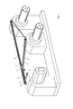
- FIG. 2 shows a collection device (1) with a linear branching linear guide (2), a traction drive (3) and a conveyor slide (4), and a boom (5) with a clamping device (9) without a processing station within the machine.
- the partition walls were omitted.
- the feed machine consists here from a spool, a drive and two unwinders and the collection device (1).
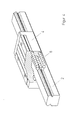
- FIG. 3 shows the collection device in a detailed version.
- a clamping mechanism (9) is provided on the boom, which is connected to the conveyor carriage (4).
- the conveyor slide (4) is connected to a coupling rod (5), which is connected to the traction mechanism drive (3).
- This can be pivoted in sections around a pivot point, so that two different linear guides can be approached via a turnout.
- the game between the radial fits (7) 1 / 10mm is the game between the radial fits (7) 1 / 10mm.
- a "leadership change" of the conveyor carriage (4) is linearly driven on the partially pivotable part of the linear guide (2) and pivoted with this part to the other linear guide (2). Subsequently, the conveyor carriage (4) can be driven linearly.
- a preferably electric drive thereby drives the gears, which pass on their movement to the traction mechanism drive (3).
- the conveyor carriage (4) in turn transmits its movement to the boom (5), which passes on its tensile force to the clamping device (9).
- the material to be transported and prestressed by the brake rollers is pulled parallel to the intake device.
- Mechanically (static / dynamic) a force is exerted on the material to be transported by the clamping device.
- the counterforce is transmitted by the boom to the conveyor carriage, as well as the moments caused by the boom.
- FIG. 4 shows a cross section of the conveyor carriage with the ball circulation chains of the linear guide.
- the ball circulation chains (8) roll on the grooves of the linear guide (2) and the grooves of the conveyor carriage (4).
- the outer part of the ball circulation chain (8) moves in the direction of movement of the conveyor carriage (4) to the reversal point of the circulating chain (8). Thereafter, the outer part becomes the inner part of the circulating chains (8).
- the embodiment of the drive unit with two recirculating ball chains (8) on the side of the linear guide a rolling surface of 270 ° of the ball circumference can be realized, which is composed of 180 ° rolling surface of the lower circulation chain and 90 ° of the upper circulation chain.
- the rolling surface of the conveyor carriage is 180 ° and 270 °.
Landscapes
- Engineering & Computer Science (AREA)
- Mechanical Engineering (AREA)
- Replacement Of Web Rolls (AREA)
- Advancing Webs (AREA)
- Intermediate Stations On Conveyors (AREA)
Applications Claiming Priority (1)
| Application Number | Priority Date | Filing Date | Title |
|---|---|---|---|
| DE201210000128 DE102012000128A1 (de) | 2012-01-06 | 2012-01-06 | Einzugsvorrichtung einer Bandwickelmaschine |
Publications (2)
| Publication Number | Publication Date |
|---|---|
| EP2612832A2 true EP2612832A2 (fr) | 2013-07-10 |
| EP2612832A3 EP2612832A3 (fr) | 2014-02-26 |
Family
ID=47561300
Family Applications (1)
| Application Number | Title | Priority Date | Filing Date |
|---|---|---|---|
| EP13000024.3A Withdrawn EP2612832A3 (fr) | 2012-01-06 | 2013-01-04 | Dispositif d'introduction d'une enrouleuse de bande |
Country Status (2)
| Country | Link |
|---|---|
| EP (1) | EP2612832A3 (fr) |
| DE (1) | DE102012000128A1 (fr) |
Cited By (5)
| Publication number | Priority date | Publication date | Assignee | Title |
|---|---|---|---|---|
| CN107946063A (zh) * | 2017-11-16 | 2018-04-20 | 天长市昭田磁电科技有限公司 | 一种变压器生产用包胶机 |
| CN111115339A (zh) * | 2020-01-17 | 2020-05-08 | 大族激光科技产业集团股份有限公司 | 胶带裁剪装置 |
| EP3693305A3 (fr) * | 2019-02-07 | 2020-11-18 | BHS Corrugated Maschinen-und Anlagenbau GmbH | Dispositif de retrait de protecteur |
| CN112278932A (zh) * | 2020-12-30 | 2021-01-29 | 虎丘影像(苏州)有限公司 | 一种双通道卷材传输机构 |
| EP3915910A1 (fr) | 2019-02-07 | 2021-12-01 | BHS Corrugated Maschinen- und Anlagenbau GmbH | Agencement de traitement /d'usinage des bandes de matière |
Family Cites Families (11)
| Publication number | Priority date | Publication date | Assignee | Title |
|---|---|---|---|---|
| US3828598A (en) | 1973-05-07 | 1974-08-13 | Gulf & Western Mfg Co | Wrapping roll adjustment for a strip coiling machine |
| DE2402768C2 (de) * | 1974-01-22 | 1978-04-20 | Maschinenfabrik Augsburg-Nuernberg Ag, 8900 Augsburg | Vorrichtung zum Einziehen von Materialbahnen in Rotationsdruckmaschinen |
| FR2365867A1 (fr) | 1976-09-22 | 1978-04-21 | Alsthom Savoisienne | Bobinages en feuilles metalliques |
| DE3017552C2 (de) * | 1980-05-08 | 1984-05-10 | Sundwiger Eisenhütte Maschinenfabrik Grah & Co, 5870 Hemer | Vorrichtung zum lagerichtigen Transport von Bandanfängen aufzuwickelnder Metallbänder zu einer Haspeltrommel |
| DE3047887A1 (de) | 1980-12-19 | 1982-07-22 | Reifenhäuser KG, 5210 Troisdorf | "vollautomatische wickel- und abbindemaschine, sowie ein wickelbundherstellverfahren fuer bunde aus rohren, schlaeuchen, kabeln, profilen usw." |
| JPH07108741B2 (ja) * | 1989-04-04 | 1995-11-22 | 株式会社東京機械製作所 | 輪転機の紙通し装置 |
| EP0425741A1 (fr) * | 1989-11-01 | 1991-05-08 | Hamada Printing Press Co. Ltd. | Dispositif d'alimentation de bande pour rotative |
| JP3677620B2 (ja) * | 2000-02-28 | 2005-08-03 | 株式会社東京機械製作所 | 輪転機の紙通し装置における切換装置 |
| DE10024013C1 (de) * | 2000-05-16 | 2001-09-27 | Koenig & Bauer Ag | Vorrichtung zum Einziehen einer Bahn |
| DE10106946A1 (de) * | 2001-02-15 | 2002-08-22 | Heidelberger Druckmasch Ag | Einzugselement zum Einziehen einer Materialbahn |
| DE10121943B4 (de) * | 2001-05-05 | 2005-04-21 | Koenig & Bauer Ag | Weiche einer Transportvorrichtung |
-
2012
- 2012-01-06 DE DE201210000128 patent/DE102012000128A1/de not_active Withdrawn
-
2013
- 2013-01-04 EP EP13000024.3A patent/EP2612832A3/fr not_active Withdrawn
Non-Patent Citations (1)
| Title |
|---|
| None * |
Cited By (10)
| Publication number | Priority date | Publication date | Assignee | Title |
|---|---|---|---|---|
| CN107946063A (zh) * | 2017-11-16 | 2018-04-20 | 天长市昭田磁电科技有限公司 | 一种变压器生产用包胶机 |
| EP3693305A3 (fr) * | 2019-02-07 | 2020-11-18 | BHS Corrugated Maschinen-und Anlagenbau GmbH | Dispositif de retrait de protecteur |
| EP3915910A1 (fr) | 2019-02-07 | 2021-12-01 | BHS Corrugated Maschinen- und Anlagenbau GmbH | Agencement de traitement /d'usinage des bandes de matière |
| US11548747B2 (en) | 2019-02-07 | 2023-01-10 | Bhs Corrugated Maschinen- Und Anlagenbau Gmbh | Release liner removal apparatus |
| US11685624B2 (en) | 2019-02-07 | 2023-06-27 | Bhs Corrugated Maschinen- Und Anlagenbau Gmbh | Material web drawing-in apparatus |
| US11691837B2 (en) | 2019-02-07 | 2023-07-04 | Bhs Corrugated Maschinen- Und Anlagenbau Gmbh | Material web drawing-in apparatus |
| CN111115339A (zh) * | 2020-01-17 | 2020-05-08 | 大族激光科技产业集团股份有限公司 | 胶带裁剪装置 |
| CN111115339B (zh) * | 2020-01-17 | 2021-06-15 | 大族激光科技产业集团股份有限公司 | 胶带裁剪装置 |
| CN112278932A (zh) * | 2020-12-30 | 2021-01-29 | 虎丘影像(苏州)有限公司 | 一种双通道卷材传输机构 |
| CN112278932B (zh) * | 2020-12-30 | 2021-03-26 | 虎丘影像(苏州)有限公司 | 一种双通道卷材传输机构 |
Also Published As
| Publication number | Publication date |
|---|---|
| EP2612832A3 (fr) | 2014-02-26 |
| DE102012000128A1 (de) | 2013-07-11 |
Similar Documents
| Publication | Publication Date | Title |
|---|---|---|
| DE19621507C1 (de) | Bahneinzugsvorrichtung für eine bahnförmiges Material verarbeitende Maschine, insbesondere eine Rollenrotations-Druckmaschine | |
| DE102008000921B4 (de) | Strecke mit linearem Kannendurchschub | |
| EP2612832A2 (fr) | Dispositif d'introduction d'une enrouleuse de bande | |
| EP3070008B1 (fr) | Dispositif d'enrubannage et son processus de fonctionnement | |
| DE102018009632B4 (de) | Vorrichtung zum Aufwickeln und Wickelwechsel von bahnförmigem Material und ein Verfahren dafür | |
| DE1260580B (de) | Wickelhaspelstaender | |
| EP1988045A1 (fr) | Machine de préparation de câbles et procédé destiné à la fabrication et au traitement d'une section de câble | |
| EP3374302B1 (fr) | Procédé et dispositif de production et d'extraction d'un produit en forme de bande | |
| DE102013002022A1 (de) | Vorrichtung zum Wickeln eines strangförmigen Wickelguts und Verfahren dazu | |
| DE102016116440B4 (de) | Transporteinrichtung zum Transportieren eines Endlosbands | |
| DE2617090A1 (de) | Vorrichtung zur behandlung von werkstoffbahnen | |
| EP3157850A1 (fr) | Dispositif de retenue et de déroulement pour matériau plat et/ou de type feuille enroulé sur des rouleaux, installation d'emballage de contenants et procédé permettant de remplacer un rouleau comprenant un matériau plat et/ou de type feuille | |
| DE102008048101B4 (de) | Bandspeicher | |
| EP2634101A2 (fr) | Banderoleuse | |
| EP0093301B1 (fr) | Dispositif pour changer le centre d'une bobine enroulée d'un matériel en bande | |
| EP0289749A1 (fr) | Dispositif pour dérouler une bande d'une bobine | |
| DE60200291T2 (de) | Umwickelmaschine mit Flanken zum Tragen von sich entlang einer geschlossenen Bahn bewegenden greifenden Zentrierdornen | |
| DE102011001835A1 (de) | Verfahren und Vorrichtung zur Verarbeitung eines Bandes | |
| DE102008061356B4 (de) | Bandeinfädelsystem sowie Verfahren zum Einführen eines Streifens | |
| EP2836351B1 (fr) | Dispositif et procédé pour guider une feuille soufflée | |
| EP3102516B1 (fr) | Dispositif d'enroulement permettant l'enroulement d'un matériau en forme de bande et procédé permettant le remplacement d'une bobine dans un dispositif d'enroulement | |
| DE20307581U1 (de) | Wickelmaschine zum kontinuierlichen Aufwickeln einer laufenden Materialbahn | |
| AT521489B1 (de) | Werkzeug-Transfervorrichtung | |
| DE102016006504A1 (de) | Vorrichtung zum Auftragen von Klebstoff auf vorwiegend flächige Materialzuschnitte | |
| EP3962848B1 (fr) | Poste de déroulement |
Legal Events
| Date | Code | Title | Description |
|---|---|---|---|
| PUAI | Public reference made under article 153(3) epc to a published international application that has entered the european phase |
Free format text: ORIGINAL CODE: 0009012 |
|
| AK | Designated contracting states |
Kind code of ref document: A2 Designated state(s): AL AT BE BG CH CY CZ DE DK EE ES FI FR GB GR HR HU IE IS IT LI LT LU LV MC MK MT NL NO PL PT RO RS SE SI SK SM TR |
|
| AX | Request for extension of the european patent |
Extension state: BA ME |
|
| RAP1 | Party data changed (applicant data changed or rights of an application transferred) |
Owner name: TEWISS-TECHNIK UND WISSEN GMBH |
|
| PUAL | Search report despatched |
Free format text: ORIGINAL CODE: 0009013 |
|
| AK | Designated contracting states |
Kind code of ref document: A3 Designated state(s): AL AT BE BG CH CY CZ DE DK EE ES FI FR GB GR HR HU IE IS IT LI LT LU LV MC MK MT NL NO PL PT RO RS SE SI SK SM TR |
|
| AX | Request for extension of the european patent |
Extension state: BA ME |
|
| RIC1 | Information provided on ipc code assigned before grant |
Ipc: B65H 20/16 20060101AFI20140117BHEP Ipc: B21C 47/24 20060101ALI20140117BHEP Ipc: B21C 47/34 20060101ALI20140117BHEP |
|
| RAP1 | Party data changed (applicant data changed or rights of an application transferred) |
Owner name: BR TECHNOLOGIES GMBH & CO. KG |
|
| 17P | Request for examination filed |
Effective date: 20140826 |
|
| RBV | Designated contracting states (corrected) |
Designated state(s): AL AT BE BG CH CY CZ DE DK EE ES FI FR GB GR HR HU IE IS IT LI LT LU LV MC MK MT NL NO PL PT RO RS SE SI SK SM TR |
|
| 17Q | First examination report despatched |
Effective date: 20170207 |
|
| STAA | Information on the status of an ep patent application or granted ep patent |
Free format text: STATUS: THE APPLICATION HAS BEEN WITHDRAWN |
|
| 18W | Application withdrawn |
Effective date: 20180213 |