EP2612834B1 - Dispositif de prévention de mou pour tige de fil métallique enroulé autour d'une bobine et procédé de prévention de mou - Google Patents
Dispositif de prévention de mou pour tige de fil métallique enroulé autour d'une bobine et procédé de prévention de mou Download PDFInfo
- Publication number
- EP2612834B1 EP2612834B1 EP12007687.2A EP12007687A EP2612834B1 EP 2612834 B1 EP2612834 B1 EP 2612834B1 EP 12007687 A EP12007687 A EP 12007687A EP 2612834 B1 EP2612834 B1 EP 2612834B1
- Authority
- EP
- European Patent Office
- Prior art keywords
- wire rod
- spool
- rotation roller
- roller
- rotating
- Prior art date
- Legal status (The legal status is an assumption and is not a legal conclusion. Google has not performed a legal analysis and makes no representation as to the accuracy of the status listed.)
- Active
Links
Images


Classifications
-
- B—PERFORMING OPERATIONS; TRANSPORTING
- B65—CONVEYING; PACKING; STORING; HANDLING THIN OR FILAMENTARY MATERIAL
- B65H—HANDLING THIN OR FILAMENTARY MATERIAL, e.g. SHEETS, WEBS, CABLES
- B65H59/00—Adjusting or controlling tension in filamentary material, e.g. for preventing snarling; Applications of tension indicators
-
- B—PERFORMING OPERATIONS; TRANSPORTING
- B65—CONVEYING; PACKING; STORING; HANDLING THIN OR FILAMENTARY MATERIAL
- B65H—HANDLING THIN OR FILAMENTARY MATERIAL, e.g. SHEETS, WEBS, CABLES
- B65H54/00—Winding, coiling, or depositing filamentary material
- B65H54/02—Winding and traversing material on to reels, bobbins, tubes, or like package cores or formers
- B65H54/10—Winding and traversing material on to reels, bobbins, tubes, or like package cores or formers for making packages of specified shapes or on specified types of bobbins, tubes, cores, or formers
-
- B—PERFORMING OPERATIONS; TRANSPORTING
- B65—CONVEYING; PACKING; STORING; HANDLING THIN OR FILAMENTARY MATERIAL
- B65H—HANDLING THIN OR FILAMENTARY MATERIAL, e.g. SHEETS, WEBS, CABLES
- B65H49/00—Unwinding or paying-out filamentary material; Supporting, storing or transporting packages from which filamentary material is to be withdrawn or paid-out
- B65H49/18—Methods or apparatus in which packages rotate
- B65H49/20—Package-supporting devices
- B65H49/24—Rollers
-
- B—PERFORMING OPERATIONS; TRANSPORTING
- B65—CONVEYING; PACKING; STORING; HANDLING THIN OR FILAMENTARY MATERIAL
- B65H—HANDLING THIN OR FILAMENTARY MATERIAL, e.g. SHEETS, WEBS, CABLES
- B65H51/00—Forwarding filamentary material
- B65H51/02—Rotary devices, e.g. with helical forwarding surfaces
- B65H51/04—Rollers, pulleys, capstans, or intermeshing rotary elements
- B65H51/08—Rollers, pulleys, capstans, or intermeshing rotary elements arranged to operate in groups or in co-operation with other elements
- B65H51/10—Rollers, pulleys, capstans, or intermeshing rotary elements arranged to operate in groups or in co-operation with other elements with opposed coacting surfaces, e.g. providing nips
-
- B—PERFORMING OPERATIONS; TRANSPORTING
- B65—CONVEYING; PACKING; STORING; HANDLING THIN OR FILAMENTARY MATERIAL
- B65H—HANDLING THIN OR FILAMENTARY MATERIAL, e.g. SHEETS, WEBS, CABLES
- B65H51/00—Forwarding filamentary material
- B65H51/20—Devices for temporarily storing filamentary material during forwarding, e.g. for buffer storage
-
- B—PERFORMING OPERATIONS; TRANSPORTING
- B65—CONVEYING; PACKING; STORING; HANDLING THIN OR FILAMENTARY MATERIAL
- B65H—HANDLING THIN OR FILAMENTARY MATERIAL, e.g. SHEETS, WEBS, CABLES
- B65H51/00—Forwarding filamentary material
- B65H51/30—Devices controlling the forwarding speed to synchronise with supply, treatment, or take-up apparatus
-
- B—PERFORMING OPERATIONS; TRANSPORTING
- B65—CONVEYING; PACKING; STORING; HANDLING THIN OR FILAMENTARY MATERIAL
- B65H—HANDLING THIN OR FILAMENTARY MATERIAL, e.g. SHEETS, WEBS, CABLES
- B65H59/00—Adjusting or controlling tension in filamentary material, e.g. for preventing snarling; Applications of tension indicators
- B65H59/38—Adjusting or controlling tension in filamentary material, e.g. for preventing snarling; Applications of tension indicators by regulating speed of driving mechanism of unwinding, paying-out, forwarding, winding, or depositing devices, e.g. automatically in response to variations in tension
-
- H—ELECTRICITY
- H01—ELECTRIC ELEMENTS
- H01F—MAGNETS; INDUCTANCES; TRANSFORMERS; SELECTION OF MATERIALS FOR THEIR MAGNETIC PROPERTIES
- H01F41/00—Apparatus or processes specially adapted for manufacturing or assembling magnets, inductances or transformers; Apparatus or processes specially adapted for manufacturing materials characterised by their magnetic properties
- H01F41/02—Apparatus or processes specially adapted for manufacturing or assembling magnets, inductances or transformers; Apparatus or processes specially adapted for manufacturing materials characterised by their magnetic properties for manufacturing cores, coils, or magnets
- H01F41/04—Apparatus or processes specially adapted for manufacturing or assembling magnets, inductances or transformers; Apparatus or processes specially adapted for manufacturing materials characterised by their magnetic properties for manufacturing cores, coils, or magnets for manufacturing coils
- H01F41/06—Coil winding
- H01F41/096—Dispensing or feeding devices
-
- B—PERFORMING OPERATIONS; TRANSPORTING
- B65—CONVEYING; PACKING; STORING; HANDLING THIN OR FILAMENTARY MATERIAL
- B65H—HANDLING THIN OR FILAMENTARY MATERIAL, e.g. SHEETS, WEBS, CABLES
- B65H2701/00—Handled material; Storage means
- B65H2701/30—Handled filamentary material
- B65H2701/37—Tapes
Definitions
- the present invention relates to a device which is installed parallel to a wire rod feeding machine feeding a wire rod by rotating a spool around which the wire rod is wound, and prevents a slack of the wire rod wound around the spool, and a method of preventing the slack.
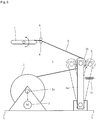
- a wire rod feeding machine 1 shown in Fig. 5 supports a spool 2 while setting a rotating axis 2a horizontally, and is provided with a motor 3 which rotates the spool 2.
- a wire rod 4 can be fed from the spool 2 by rotating the spool 2 by means of the motor 3, and the wire rod 4 fed out of the spool 2 is wound around a pulley 5b which is pivotally supported to a leading end of an oscillating bar 5a corresponding to a tension applying device 5 so as to be converted, and passes through a wire guide 6 so as to be guided to a winding core 7 which winds the wire rod 4.
- the oscillating bar 5a is provided with a spring 5c corresponding to a tension applying mechanism which energizes in a direction of moving the pulley 5b away from the winding core 7, and a predetermined tensile force is applied to the wire rod 4 which is converted in the pulley 5b, on the basis of an energizing force of the spring 5c.
- the motor 3 is structured such that it rotates the spool 2 so as to feed the wire rod 4 at a time when the oscillating bar 5a is tilted to the winding core 7 side as shown by a one-dot chain line, and stops the rotation of the spool 2 so as to stop the feeding of the wire rod 4 at a time when the oscillating bar 5a is tilted to a direction of moving away from the winding core 7 as shown by a two-dot chain line on the basis of the feeding of the wire rod 4.
- Patent Document 1 Japanese Patent Application Laid-open No. H3-159541 ( Fig. 1 and Fig. 4 )
- the spring 5c energizing in the direction of moving the pulley 5b away from the winding core 7 applies a force energizing in a direction of moving away from the winding core 7 to the wire rod 4, the spring 5c confers a resistance against a motor which rotates the winding core 7 and is not illustrated. Accordingly, it is preferable that the force energizing the wire rod 4 in the direction of moving away from the winding core 7 is as weak as possible, as long as the wire rod 4 is wound around the winding core 7 without slacking.
- a winding speed of the wire rod 4 wound around the winding core 7 is not constant, and in the case that the cross section of the winding core 7 is rectangular and a longer side thereof is significantly longer in comparison with a shorter side, the speed of the wire rod 4 significantly changes, and a movement and a stop thereof are alternately repeated. Accordingly, the feeding and the stop of the wire rod 4 are alternately repeated in the wire rod feeding machine 1, and the winding speed in the winding machine substantially depends on the feeding speed of the wire rod 4 in the wire rod feeding machine 1. In the case that the comparatively large spool 2 is rotated, it becomes hard to rapidly feed the wire rod due to its inertia, and there is a problem that it becomes hard to increase the winding speed.
- JP H02 137343 A describes a wire feed apparatus.
- a wire sent out from feed rollers is fed to the supply side through guides. During this process, the wire is bent by its own weight between the guides; a turn part is formed. When the turn part is reduced gradually and the wire approaches the metal rod, a sensor is turned on, thereby detecting a state of tension; a motor is turned by the detection signal and the wire is sent out again.
- JP S60 6794 U describes another wire feed apparatus.
- An object of the present invention is to provide a slack preventing device for a wire rod wound around a spool, which can prevent a slack of the wire rod in the spool by preventing the wire rod fed by a rotation of the spool from returning to the spool, and a slack preventing method of the same.
- the present invention relates to a wire rod slack preventing device which is installed parallel to a wire rod feeding machine feeding a wire rod by rotating a spool around which the wire rod is wound.
- a characteristic structure thereof exists in provision of a reverse rotation roller having a rotating axis which is parallel to a rotating axis of a spool and rotating in a reverse direction to a rotating direction of the spool while being in contact with the spool, a forward rotation roller having a rotating axis which is parallel to the rotating axis of the reverse rotation roller and rotating in the same direction as the spool while being in contact with the reverse rotation roller, and a pinching roller having a rotating axis which is parallel to the rotating axis of the forward rotation roller and pinching a wire rod which is fed out of the spool together with the forward rotation roller.
- the slack preventing device for the wire rod wound around the spool is further provided with a pair of support posts which are erected so as to pinch the spool, in which the rotating axis is set horizontally, from both sides in a direction of the rotating axis thereof, a transverse support bar which is provided in such a manner as to be bridged between the pair of support posts, and a pair of pivotally supporting bodies which are provided in the transverse support bar to be spaced apart from each other at a wider distance than a width, in the direction of the rotating axis, of the spool, and both end portions of the reverse rotation roller, the forward rotation roller and the pinching roller are rotatably supported to the pair of pivotally supporting bodies.
- the wire rod feeding machine is preferably structured such that it is provided with a deflection sensor which detects a deflection of the fed wire rod in a non-contact manner, rotates the spool in the case that the deflection sensor detects a reduction of the slack or the fed wire rod, and stops the rotation of the spool in the case that the deflection sensor detects a predetermined amount of slack of the fed wire rod.
- the other aspect of the present invention relates to a slack preventing method for a wire rod in a wire rod feeding machine which feeds the wire rod by rotating a spool around which the wire rod is wound.
- the forward rotation roller rotating together with the rotation of the spool pinches and draws the wire rod which is fed out due to the rotation of the spool together with the pinching roller, it is possible to prevent the wire rod which is fed out by rotating the spool from returning to the spool, whereby the fed wire rod is not loosened in the spool, and it is possible to prevent the slack of the wire rod in the spool. Further, since the forward rotation roller rotates together with the rotation of the spool, it is possible to make the other power than a power for rotating the spool unnecessary.
- a wire rod slack preventing device 20 in the present invention is shown in Fig. 1 to Fig. 3 .
- the wire rod slack preventing device 20 is installed parallel to a wire rod feeding machine 10 which feeds out a wire rod 11 by rotating a spool 12 around which the wire rod 11 is wound.
- the wire rod 11 in this embodiment is shown as a case that a so-called flat square wire having a rectangular cross sectional shape is employed, however, the wire rod 11 may be constructed by a so-called square wire having a square cross section, or may be constructed by a so-called round wire having a circular cross section. Further, the wire rod 11 may be constructed by a long object, for example, a film.
- the spool 12 around which the wire rod 11 is wound has a columnar body portion 12a ( Fig. 2 and Fig. 4 ) in which the wire rod 11 is actually wound around an outer periphery, and discoid flange portions 12b which are formed coaxially in both ends in an axial direction of the body portion 12a.
- the wire rod feeding machine 10 rotating the spool 12 is provided with a pair of bases 13 which are installed in such a manner as to pinch the flange portions 12b in both sides of the spool 12 in which a rotating axis is set horizontally, from an outer side while being spaced, a pair of support rollers 14 which are bridged between the pair of bases 13 and on which the spool 12 is mounted, and a motor 16 which rotates any one or both of the pair of support rollers 14.
- the motor 16 rotating one of the pair of support rollers 14 is provided.
- the motor 16 is structured such that it can rotate the spool 12 which is mounted on the pair of support rollers 14, by rotating one or both of the pair of support rollers 14.
- the wire rod feeding machine 10 is provided with a deflection sensor 17 which detects a deflection of the wire rod 11 fed out of the spool 12 in a non-contact manner.
- the deflection sensor 17 is provided with a pair of support posts 17a which are erected in both sides in a width direction of the fed wire rod 11 while being spaced at a predetermined distance in such a manner as to pinch the wire rod 11.
- the pair of support posts 17a are provided in their lower portions with lower sensors 17b which detect in a non-contact manner a case that the bending wire rod 11 comes down on the basis of its own weight, and are provided in their upper portions with upper sensors 17c which detect in a non-contact manner a case that the bending wire rod 11 is taken back so as to rise. Further, in the case that the upper sensors 17c in the deflection sensor 17 detect a reduction of the deflection of the fed wire rod 11, the spool 12 is rotated by driving the motor 16, and in the case that the lower sensor 17b in the deflection sensor 17 detects a predetermined amount of deflection of the fed wire rod 11, the rotation of the spool 12 is stopped by stopping the driving of the motor 16.
- the wire rod slack preventing device 20 which is installed parallel to the wire rod feeding machine 10 mentioned above is provided with a pair of support posts 21 which are provided in outer sides of the pair of bases 13 in a standing manner so as to pinch the spool 12 which is mounted to the pair of support rollers 14 while setting a rotating axis horizontally from both sides in a direction of the rotating axis.
- Each of the pair of support posts 21 is provided with a movable member 22 which can be moved up and down so as to be fixed at an optional position, and a transverse support bar 23 is bridged between the movable members 22.
- the transverse support bar 23 is horizontally bridged between the pair of support posts 21 via the movable members 22 in such a manner as to be parallel to the rotating axis of the spool 12.
- the transverse support bar 23 is provided with a pair of pivotally supporting bodies 24 while being spaced at a wider distance than a width in a direction of the rotating axis of the spool 12.
- Each of the pair of pivotally supporting bodies 24 is formed as a plate-like shape which is longer in a vertical direction, and an upper portion thereof is attached to the transverse support bar 23. Further, both end portions of a reverse rotation roller 26, a forward rotation roller 27 and a pinching roller 28 are rotatably supported to the pair of pivotally supporting bodies 24.
- the reverse rotation roller 26 is provided in the lowermost ends of the pair of pivotally supporting bodies 24.
- the reverse rotation roller 26 is provided in parallel to the rotating axis of the spool 12. Further, the reverse rotation roller 26 is provided in such a manner as to come into contact with the spool 12.
- the reverse rotation roller 26 in the embodiment is shown as a case that an outer periphery thereof is in contact with the outer peripheries of the flange portions 12b in the spool 12, as shown in Fig. 2 or Fig. 4 . Since the outer periphery comes into contact with the spool 12 as mentioned above, the reverse rotation roller 26 is structured such that it rotates in a reverse direction to the rotating direction due to the rotation of the spool 12.
- the forward rotation roller 27 has a rotating axis which is parallel to the rotating axis of the reverse rotation roller 26, and is pivotally supported its both ends to the pair of pivotally supporting bodies 24 above the reverse rotation roller 26 in such a manner that an outer periphery thereof comes into contact with the outer periphery of the reverse rotation roller 26. Accordingly, the forward rotation roller 27 is structured such that it rotates in a reverse direction to the rotating direction of the reverse rotation roller 26, that is, the same direction as the rotating direction of the spool 12, d of the rotation of the reverse rotation roller 26 in a reverse direction to the direction of the rotating axis of the spool 12.
- the pinching roller 28 has a rotating axis which is parallel to the rotating axis of the forward rotation roller 27, and is pivotally supported its both ends to the pair of pivotally supporting bodies 24 above the forward rotation roller 27 in such a manner as to pinch the wire rod 11 which is fed out of the spool 12 together with the forward rotation roller 27.
- a rail 29 extending up and down is provided above a pivotally supporting point which pivotally supports the forward rotation roller 27 in each of the pair of pivotally supporting bodies 24, and a movable slider 31 is further provided in the rail 29. Both ends of the pinching roller 28 are pivotally supported to the sliders 31, and the pinching roller 28 is pivotally supported it both ends to the pair of pivotally supporting bodies 24, via the sliders 31.
- the pivotally supporting body 24 is provided with a spring 32 which energizes the slider 31 toward the downward forward rotation roller 27, the pinching roller 28 is structured such that it pinches the wire rod 11 which is fed out of the spool 12 together with the forward rotation roller 27, on the basis of an energizing force of the spring 32. Accordingly, in the case that the forward rotation roller 27 rotates in the same direction as the rotating direction of the spool 12, the pinching roller 28 pinching the wire rod 11 together with the forward rotation roller 27 rotates in the reverse direction to the forward rotation roller 27, and the forward rotation roller 27 and the pinching roller 28 are structured such that they draw the wire rod 11 pinched by them from the spool 12.
- the outer peripheries of the reverse rotation roller 26, the forward rotation, roller 27 and the pinching roller 28 are formed by a resin such as a polyurethane or the like which does not apply any damage to the wire rod 11 even if the wire rod 11 comes into contact therewith so as to rob.
- the wire rod 11 which is drawn out of the spool 12 while being pinched by the rotating forward rotation roller 27 and pinching roller 28 is guided to a device which uses the wire rod 11, after passing between the pair of support posts 17a in the deflection sensor 17.
- a case that the wire rod 11 drawn out of the spool 12 so as to be fed is supplied to a winding machine 33 is exemplified, and the wire rod 11 is guided to a winding core 33b after passing through a wire guide 33a in the winding machine 33.
- the wire rod 11 fed out of the spool 12 is wound around the winding core 33b by rotating the winding core 33b in the winding machine 33.
- the slack preventing method for the wire rod 11 in the present invention is a slack preventing method for the wire rod 11 in the wire rod feeding machine 10 which feeds the wire rod 11 by rotating the spool 12 around which the wire rod 11 is wound, as shown in Fig. 4 .
- a characteristic point thereof exists in rotating the reverse rotation roller 26 having the rotating axis which is parallel to the rotating axis of the spool 12, in the reverse direction to the rotating direction of the spool 12 while being in contact with the spool 12, rotating the forward rotation roller 27 having the rotating axis which is parallel to the rotating axis of the reverse rotation roller 26, in the same direction as the spool 12 while being in contact with the reverse rotation roller 26, pinching the wire rod 11 which is fed out of the spool 12 by the pinching roller 28 having the rotating axis which is parallel to the rotating axis of the forward rotation roller 27 and the forward rotation roller 27, and drawing the wire rod 11 which is fed out due to the rotation of the spool 12, while pinching the wire rod 11 by the forward rotation roller 27 which rotates with the rotation of the spool 12, together with the pinching roller 28.
- the wire rod slack preventing device 20 mentioned above Since the wire rod 11 is fed by rotating the spool 12, the wire rod slack preventing device 20 mentioned above is first of all installed in the vicinity of the winding machine 33 side of the wire rod feeding machine 10. The installation is carried out by arranging in a standing manner the pair of support posts 21 in the slack preventing device 20 in the outer sides of the pair of bases 13 in the wire rod feeding machine 10, and pinching the spool 12 by the pair of support posts 21 from both sides in the direction of the rotating axis.
- the reverse rotation roller 26 is brought into contact with the outer periphery of the circular flange portion 12b in the spool 12 by moving up and down the pair of pivotally supporting bodies 24 to which the pinching roller 28, the forward rotation roller 27 and the reverse rotation roller 26 are pivotally supported.
- the upward and downward movement of the pair of pivotally supporting bodies 24 is carried out by moving up and down the movable members 22 which are provided in the pair of support posts 21 so as to be movable up and down, thereby moving up and down the pair of pivotally supporting bodies 24 together with the overhead transverse support bar 23.
- a position of the pair of support posts 21 of the wire rod slack preventing device 20 is adjusted in the winding machine 33 side of the wire rod feeding machine 10, in such manner that a portion between the pinching roller 28 and the forward rotation roller 27 is positioned at a locus which the wire rod 11 heading for the winding machine 33 from the spool 12 depicts.
- the wire rod 11 fed out of the spool 12 is inserted between the pinching roller 28 and the forward rotation roller 27, and the wire rod 11 fed out of the spool 12 is pinched by the pinching roller 28 and the forward rotation roller 27, the pinching roller 28 having the rotating axis which is parallel to the rotating axis of the forward rotation roller 27.
- the pinching roller 28 is raised against the energizing force of the spring 32, a gap between the pinching roller 28 and the forward rotation roller 27 is expanded, and the wire rod 11 fed out of the spool 12 is inserted into the expanded gap.
- the raised pinching roller 28 is again moved down, and the gap between the pinching roller 28 and the forward rotation roller 27 is reduced on the basis of the energizing force of the spring 32, whereby the wire rod 11 fed out of the spool 12 is pinched by the pinching roller 28 and the forward rotation roller 27. Accordingly, the installation of the wire rod slack preventing device 20 in the vicinity of the wire rod feeding machine 10 is finished.
- the wire rod 11 is actually fed by rotating the spool 12, and is passed through the wire guides 33a in the winding machine 33 via the deflection sensor 17, and the end portion of the wire rod 11 is thereafter locked to the winding core 33b.
- the wire rod 11 from the spool 12 comparatively a lot of wire rod 11 is fed in correspondence to the deflection of the wire rod 11 between the winding machine 33 and the slack preventing device 20, and the rotation of the spool 12 is thereafter stopped.
- the coil winding by the winding machine 33 is started, and the wire rod 11 is wound around the rotating winding core 33b.
- any force which pulls back the wound wire rod 11 to the spool 12 side is not applied. Accordingly, in comparison with the conventional structure in which the force pulling back the wound wire rod to the spool side is applied, it is possible to reduce a resistance against a motor which rotates the winding core 33b and is not illustrated. Further, it is possible to increase the rotating speed of the winding core 33b so as to carry out the coil winding at a comparatively high speed.
- the wire rod 11 between the winding machine 33 and the slack preventing device 20 is wound around the winding core 33b by starting the coil winding, a degree of deflection in the wire rod 11 between them is reduced little by little. Further, as shown by a one-dot chain line in Fig. 2 , the upper sensor 17c in the deflection sensor 17 detects the reduction of the deflection of the fed wire rod 11, the wire rod feeding machine 10 again rotates the spool 12 and again feeds the wire rod 11.
- any one or both of the pair of rollers 14 is rotated by driving the motor 16 in the wire rod feeding machine 10, the spool 12 which is mounted on the pair of rollers 14 and around which the wire rod 11 is wound is rotated, and the wire rod 11 is newly fed at an amount which is equal to or more than a winding amount around the winding core 33b.
- the reverse rotation roller 26 rotates in the reverse direction to the rotating direction of the spool 12 since the outer periphery of the reverse rotation roller 26 is in contact with the outer periphery of the circular flange portion 12b in the spool 12. Further, since the reverse rotation roller 26 has the rotating axis which is parallel to the rotating axis of the spool 12, and the forward rotation roller 27 having the rotating axis which is parallel to the rotating axis of the reverse rotation roller 26 is in contact with the reverse rotation roller 26, the forward rotation roller 27 rotates in the same direction as the spool 12 together with the rotation of the reverse rotation roller 26.
- the pinching roller 28 and the forward rotation roller 27 are arranged in the direction in which the wire rod 11 heads for the winding machine 33 from the spool 12, the wire rod 11 which is pinched by the forward rotation roller 27 and the pinching roller 28 heads for the winding machine 33 without changing its direction. Accordingly, the direction of the wire rod 11 is not significantly changed by the pinching roller 28 and the forward rotation roller 27, and a curl is not generated in the wire rod 11 due to the change of the direction. Further, since the forward rotation roller 27 rotates together with the rotation of the spool 12, it is possible to make the other power than the power for rotating the spool 12 unnecessary.
- an outer diameter of the flange portion 12b in the spool 12 is generally larger than an outer diameter of the wire rod 11 which is wound around the winding drum portion 12a of the spool 12.
- the amount of the wire rod 11 which is drawn on the basis of the rotation of the forward rotation roller 27 becomes larger, in comparison with the amount of the wire rod 11 which is fed due to the rotation of the spool 12, and an error is generated between the feeding amount and the drawing amount.
- the reverse rotation roller 26 rotating the forward rotation roller 27 is structured such as to come into contact with the outer periphery in the flange portion 12b of the spool 12, the error can be absorbed by a slip between the reverse rotation roller 26 and the flange portion 12b in the spool 12, or a slip between the reverse rotation roller 26 and the forward rotation roller 27. Further, there is a case that a slip is generated between the wire rod 11 and the forward rotation roller 27 which pinches the wire rod 11 together with the pinching roller 28, thereby absorbing the error generated between the feeding amount and the drawing amount of the wire rod 11.
- the amount of deflection of the wire rod 11 between the winding machine 33 and the slack preventing device 20 is increased by making the amount of the wire rod 11 which is fed out of the spool 12 more than the amount of the wire rod 11 which the winding core 33b winds.
- the lower sensor 17b in the deflection sensor 17 detects a predetermined amount of slack of the fed wire rod 11
- the newly feeding of the wire rod 11 from the spool 12 is inhibited by stopping the rotation of the spool 12.
- the winding speed in the winding machine 33 does not depend on the feeding speed of the wire rod 11 in the wire rod feeding machine 10, and even in the case that the comparatively larger spool 12 is rotated, it is possible to sufficiently increase the winding speed of the winding machine 33 by setting comparatively a lot of wire rod 11 in the previously fed state.
Landscapes
- Engineering & Computer Science (AREA)
- Power Engineering (AREA)
- Manufacturing & Machinery (AREA)
- Unwinding Of Filamentary Materials (AREA)
- Guides For Winding Or Rewinding, Or Guides For Filamentary Materials (AREA)
Claims (4)
- Système de prévention de mou comprenant :une machine d'alimentation en fil machine (10) qui fournit un fil machine (11) en faisant tourner une bobine (12) autour de laquelle le fil machine (11) est enroulé ; etun dispositif de prévention de mou (20) installé parallèlement à la machine d'alimentation en fil machine (10), caractérisé en ce que le dispositif de prévention de mou (20) comprend :un rouleau à rotation inverse (26) ayant un axe de rotation qui est parallèle à un axe de rotation de la bobine (12) et tournant dans une direction inverse à une direction de rotation de la bobine (12) tout en étant en contact avec la bobine (12) ;un rouleau à rotation vers l'avant (27) ayant un axe de rotation qui est parallèle à un axe de rotation du rouleau à rotation inverse (26) et tournant dans la même direction que la bobine (12) tout en étant en contact avec le rouleau à rotation inverse (26) ; etun rouleau pinceur (28) ayant un axe de rotation qui est parallèle à l'axe de rotation du rouleau à rotation vers l'avant (27) et pinçant le fil machine (11) qui est sorti de la bobine (12), conjointement avec le rouleau à rotation vers l'avant (27) ;dans lequel la bobine (12) comporte :une partie de corps en forme de colonne (12a) autour d'une périphérie externe de laquelle le fil machine (11) est enroulé ; etdes parties brides circulaires (12b) formées coaxialement dans les deux extrémités dans une direction axiale de la partie de corps (12a), une périphérie externe du rouleau à rotation inverse (26) étant en contact avec des périphéries externes des parties brides circulaires (12b),dans lequel un diamètre externe de chacune des parties brides circulaires (12b) est plus important qu'un diamètre externe du fil machine (11) qui est enroulé autour de la partie tambour d'enroulement (12a) de la bobine (12) de telle sorte qu'une quantité de fil machine (11) qui est tirée sur la base de la rotation du rouleau à rotation vers l'avant (27) soit plus importante qu'une quantité de fil machine (11) qui est transmise en raison de la rotation de la bobine (12), etdans lequel une erreur qui est générée entre la quantité d'alimentation du fil machine (11) et la quantité d'étirage du fil machine (11) est absorbée par un glissement entre le rouleau à rotation inverse (26) et la partie bride circulaire (12b) dans la bobine (12) ou par un glissement entre le rouleau à rotation inverse (26) et le rouleau à rotation vers l'avant (27) .
- Système de prévention de mou selon la revendication 1,
dans lequel le dispositif de prévention de mou (20) comprend en outre :une paire de montants de support (21) qui sont érigés de telle manière à pincer la bobine (12), dans laquelle l'axe de rotation est défini horizontalement, à partir des deux côtés dans une direction de l'axe de rotation de cette dernière ;une barre de support transversale (23) qui est disposée de sorte à faire la liaison entre la paire de montants de support (21) ; etune paire de corps de support pivotants (24) qui sont disposés sur la barre de support transversale (23) de sorte à être espacés l'un de l'autre sur une distance plus étendue qu'une largeur, dans la direction de l'axe de rotation, de la bobine (12),dans lequel les deux parties d'extrémité du rouleau à rotation inverse (26), les deux parties d'extrémité du rouleau à rotation vers l'avant (27) et les deux parties d'extrémité du rouleau pinceur (28) sont supportées en rotation par la paire de corps de support pivotants (24). - Système de prévention de mou selon la revendication 1 ou 2,
dans lequel la machine d'alimentation en fil machine (10) est pourvue d'un capteur de déviation (17) qui détecte une déviation du fil machine transmis (11) sans contact, fait tourner la bobine (12) lorsque le capteur de déviation (17) détecte une diminution du mou du fil machine transmis (11) et arrête la rotation de la bobine (12) lorsque le capteur de déviation (17) détecte une quantité prédéterminée de mou du fil machine transmis (11). - Procédé de prévention de mou pour une machine d'alimentation en fil machine (10) qui fournit un fil machine (11) en faisant tourner une bobine (12) autour de laquelle le fil machine (11) est enroulé ;
le procédé étant caractérisé en ce qu'il consiste :à faire tourner un rouleau à rotation inverse (26), ayant un axe de rotation qui est parallèle à un axe de rotation de la bobine (12), dans une direction inverse à une direction de rotation de la bobine (12) tout en étant en contact avec la bobine (12) ;à faire tourner un rouleau à rotation vers l'avant (27), ayant un axe de rotation qui est parallèle à l'axe de rotation du rouleau à rotation inverse (26), dans la même direction que la bobine (12) tout en étant en contact avec le rouleau à rotation inverse (26) ;à pincer le fil machine (11) qui est sorti de la bobine (12) au moyen d'un rouleau pinceur (28) ayant un axe de rotation qui est parallèle à l'axe de rotation du rouleau à rotation vers l'avant (27) ; età tirer le fil machine (11) qui est sorti en raison de la rotation de la bobine (12) tout en pinçant le fil machine (11) au moyen du rouleau à rotation vers l'avant (27), qui tourne avec la rotation de la bobine (12), conjointement avec le rouleau pinceur (28) ;dans lequel la bobine (12) comporte :une partie de corps en forme de colonne (12a) autour d'une périphérie externe de laquelle le fil machine (11) est enroulé ; etdes parties brides circulaires (12b) formées coaxialement dans les deux extrémités dans une direction axiale de la partie de corps (12a), une périphérie externe du rouleau à rotation inverse (26) étant en contact avec des périphéries externes des parties brides circulaires (12b),dans lequel un diamètre externe de chacune des parties brides circulaires (12b) est plus important qu'un diamètre externe du fil machine (11) qui est enroulé autour de la partie tambour d'enroulement (12a) de la bobine (12) de telle sorte qu'une quantité de fil machine (11) qui est tirée sur la base de la rotation du rouleau à rotation vers l'avant (27) soit plus importante qu'une quantité de fil machine (11) qui est transmise en raison de la rotation de la bobine (12), etdans lequel une erreur qui est générée entre la quantité d'alimentation du fil machine (11) et la quantité d'étirage du fil machine (11) est absorbée par un glissement entre le rouleau à rotation inverse (26) et la partie bride circulaire (12b) dans la bobine (12) ou par un glissement entre le rouleau à rotation inverse (26) et le rouleau à rotation vers l'avant (27) .
Applications Claiming Priority (1)
| Application Number | Priority Date | Filing Date | Title |
|---|---|---|---|
| JP2012000309A JP5797116B2 (ja) | 2012-01-05 | 2012-01-05 | スプールに巻回された線材の緩み防止装置 |
Publications (3)
| Publication Number | Publication Date |
|---|---|
| EP2612834A2 EP2612834A2 (fr) | 2013-07-10 |
| EP2612834A3 EP2612834A3 (fr) | 2014-09-17 |
| EP2612834B1 true EP2612834B1 (fr) | 2018-08-01 |
Family
ID=47602689
Family Applications (1)
| Application Number | Title | Priority Date | Filing Date |
|---|---|---|---|
| EP12007687.2A Active EP2612834B1 (fr) | 2012-01-05 | 2012-11-13 | Dispositif de prévention de mou pour tige de fil métallique enroulé autour d'une bobine et procédé de prévention de mou |
Country Status (4)
| Country | Link |
|---|---|
| EP (1) | EP2612834B1 (fr) |
| JP (1) | JP5797116B2 (fr) |
| KR (1) | KR101361573B1 (fr) |
| CN (1) | CN103193106B (fr) |
Families Citing this family (28)
| Publication number | Priority date | Publication date | Assignee | Title |
|---|---|---|---|---|
| KR101415116B1 (ko) * | 2013-07-12 | 2014-07-04 | 서울대학교산학협력단 | 와이어 늘어짐 방지 장치 |
| CN105293182A (zh) * | 2014-06-16 | 2016-02-03 | 蓝星(北京)化工机械有限公司 | 变速收丝机 |
| CN104085728A (zh) * | 2014-07-09 | 2014-10-08 | 新兴铸管股份有限公司 | 天车钢丝绳更换装置 |
| CN104986613A (zh) * | 2015-05-27 | 2015-10-21 | 国家电网公司 | 旧线回收装置 |
| CN104891257B (zh) * | 2015-06-16 | 2017-11-10 | 长缆电工科技股份有限公司 | 自动控制的电缆展放装置 |
| KR102540142B1 (ko) | 2015-11-10 | 2023-06-05 | 삼성에스디아이 주식회사 | 전극조립체 권취장치 |
| CN105668310B (zh) * | 2016-01-25 | 2019-04-09 | 东莞市森佳机械有限公司 | 电线放卷整线装置 |
| CN105855728A (zh) * | 2016-06-23 | 2016-08-17 | 福建龙净环保股份有限公司 | 一种电除尘器阴极线的全自动生产设备 |
| CZ307263B6 (cs) * | 2016-11-21 | 2018-05-02 | Rieter Cz S.R.O. | Zařízení pro sledování průvěsu přástu před navíjecím zařízením přípravárenského stroje pro výrobu přástu |
| CN107244629A (zh) * | 2017-07-20 | 2017-10-13 | 上海辛格林纳新时达电机有限公司 | 一种卷绕机构和悬挂设备 |
| CN108861855B (zh) * | 2018-04-23 | 2020-12-29 | 绵阳聚贤自动化设备有限公司 | 一种智能排线绕线装置 |
| CN108529330B (zh) * | 2018-05-28 | 2023-07-21 | 深圳市金洲精工科技股份有限公司 | 轻型线材定位拉料装置 |
| CN108750814A (zh) * | 2018-08-29 | 2018-11-06 | 浙江中兴电缆有限公司 | 卷线系统中的上料子系统 |
| CN109264476B (zh) * | 2018-09-04 | 2024-03-26 | 广州捷和电子科技有限公司 | 透光防粘膜组件 |
| CN109188635A (zh) * | 2018-10-31 | 2019-01-11 | 广东亨通光电科技有限公司 | 一种螺旋铠装束缆的收线装置及铠装光缆 |
| JP6836613B2 (ja) * | 2019-03-08 | 2021-03-03 | トクセン工業株式会社 | 線材巻取り装置および線材巻取り方法 |
| CN110228728A (zh) * | 2019-04-22 | 2019-09-13 | 苏州创易技研股份有限公司 | 扁线放线机 |
| CN114174206B (zh) * | 2019-09-30 | 2024-02-02 | 株式会社藤仓 | 光纤的拉出装置、光纤的拉出方法、以及光纤的检查方法 |
| CN110775720B (zh) * | 2019-10-29 | 2022-07-01 | 国网山东省电力公司聊城供电公司 | 一种电力配网旁路作业用电缆架 |
| CN110790084B (zh) * | 2019-11-12 | 2021-03-16 | 安徽正美线业科技有限责任公司 | 一种生产涤纶金属复合纱线用的导线机构 |
| JP7613003B2 (ja) * | 2020-05-27 | 2025-01-15 | 住友電気工業株式会社 | 光ファイバ集合体の製造方法および製造装置 |
| CN111620183A (zh) * | 2020-06-08 | 2020-09-04 | 杭州伟博思文化传播有限公司 | 一种收卷质量更佳的自动导线并限位的光纤收卷辅助装置 |
| CN111776840B (zh) * | 2020-07-22 | 2022-03-18 | 东莞新恩祥机械配件有限公司 | 一种可避免出现放线混乱的永磁式放线装置 |
| JP7546901B2 (ja) * | 2020-10-15 | 2024-09-09 | 株式会社ユタカメイク | リール用架台 |
| CN113334770B (zh) * | 2021-07-06 | 2021-11-30 | 中国科学院重庆绿色智能技术研究院 | 一种适用于3d打印丝盘的振动防松器及其使用方法 |
| CN117361179A (zh) * | 2022-06-30 | 2024-01-09 | 北京众驰伟业科技发展有限公司 | 一种测试杯盘传送装置和方法 |
| CN116692586B (zh) * | 2023-08-09 | 2023-10-20 | 浙江富浦线缆有限公司 | 一种铜包钢线加工用收卷装置 |
| CN119190954B (zh) * | 2024-11-28 | 2025-04-22 | 江苏巨豪矿山机械设备有限公司 | 一种矿山机械设备放线架 |
Citations (1)
| Publication number | Priority date | Publication date | Assignee | Title |
|---|---|---|---|---|
| JPS606794U (ja) * | 1983-06-28 | 1985-01-18 | 株式会社 南星 | キヤプスタンウインチにおけるワイヤ−ロ−プの巻取り繰出し装置 |
Family Cites Families (12)
| Publication number | Priority date | Publication date | Assignee | Title |
|---|---|---|---|---|
| CH233661A (de) * | 1943-08-02 | 1944-08-15 | Zueblin Marcel | Vorrichtung zum Verlegen von Draht bzw. Kabel. |
| US2769209A (en) * | 1949-10-29 | 1956-11-06 | Schiess Ag | Lap or bobbin feed system for spinning machines |
| CH575877A5 (fr) * | 1972-11-10 | 1976-05-31 | Schuster & Co F M N | |
| DE8609191U1 (de) * | 1986-04-05 | 1986-08-07 | HTS-Elektrotechnik GmbH, 5206 Neunkirchen-Seelscheid | Abwickelvorrichtung für biegeempfindliches Profilmaterial |
| JPH02137343A (ja) * | 1988-11-18 | 1990-05-25 | Matsushita Electric Ind Co Ltd | ワイヤ送り装置 |
| JP2660073B2 (ja) | 1989-11-15 | 1997-10-08 | 株式会社東芝 | 回転電機の巻線装置 |
| JP2862107B2 (ja) * | 1991-12-16 | 1999-02-24 | 村田機械株式会社 | 弾性糸繰り出し装置 |
| EP0648701A1 (fr) * | 1993-10-19 | 1995-04-19 | Teijin Seiki Company Limited | Machine d'enroulement de fil |
| US6039286A (en) * | 1995-12-15 | 2000-03-21 | Illinois Tool Works Inc. | Inertial strap tensioning apparatus and method for strapping machine |
| JP4116272B2 (ja) | 2001-08-09 | 2008-07-09 | 住友電工スチールワイヤー株式会社 | アンダーローラ |
| MX2008011461A (es) * | 2006-03-09 | 2008-09-24 | Rib Loc Australia | Metodo y aparato para estabilizar una banda durante su bobinado. |
| EP2112258B1 (fr) * | 2008-04-25 | 2016-05-11 | Maschinenfabrik Rieter Ag | Dispositif et procédé d'enroulement d'une mèche sur une bobine |
-
2012
- 2012-01-05 JP JP2012000309A patent/JP5797116B2/ja active Active
- 2012-11-13 EP EP12007687.2A patent/EP2612834B1/fr active Active
- 2012-11-30 CN CN201210505859.9A patent/CN103193106B/zh active Active
- 2012-12-04 KR KR1020120139374A patent/KR101361573B1/ko active Active
Patent Citations (1)
| Publication number | Priority date | Publication date | Assignee | Title |
|---|---|---|---|---|
| JPS606794U (ja) * | 1983-06-28 | 1985-01-18 | 株式会社 南星 | キヤプスタンウインチにおけるワイヤ−ロ−プの巻取り繰出し装置 |
Also Published As
| Publication number | Publication date |
|---|---|
| CN103193106B (zh) | 2015-05-13 |
| CN103193106A (zh) | 2013-07-10 |
| EP2612834A3 (fr) | 2014-09-17 |
| EP2612834A2 (fr) | 2013-07-10 |
| JP2013139320A (ja) | 2013-07-18 |
| JP5797116B2 (ja) | 2015-10-21 |
| KR101361573B1 (ko) | 2014-02-12 |
| KR20130080759A (ko) | 2013-07-15 |
Similar Documents
| Publication | Publication Date | Title |
|---|---|---|
| EP2612834B1 (fr) | Dispositif de prévention de mou pour tige de fil métallique enroulé autour d'une bobine et procédé de prévention de mou | |
| KR101500597B1 (ko) | 방사 권취 장치 및 방사 권취 설비 | |
| CN102530647B (zh) | 焊丝重绕装置及焊丝重绕方法 | |
| NL2004285A (en) | Method and apparatus for rewinding welding wire. | |
| CN101918628B (zh) | 筒状加捻纱制造装置 | |
| JP2013520379A5 (fr) | ||
| CN102372177B (zh) | 胶片的间歇输送装置和胶片的间歇输送方法 | |
| KR101017642B1 (ko) | 라인형 금속재 성형장치 | |
| WO2018230494A1 (fr) | Dispositif de distribution de bande et procédé de distribution de bande | |
| JP5623794B2 (ja) | 巻線用線材のバックテンション付与装置及びそのバックテンション付与方法 | |
| JP4996949B2 (ja) | 光ファイバ担持用スロット貯線装置および光ファイバ担持用スロット貯線方法 | |
| KR102135724B1 (ko) | 권취장치 | |
| EP1595838B1 (fr) | Procede et dispositif de stockage temporaire d'un corps lineaire | |
| CN115106399B (zh) | 一种冷轧钢筋上料方法 | |
| JP5538478B2 (ja) | 光ファイバの巻取方法および巻取装置、ならびに光ファイバの製造方法 | |
| CN104870350B (zh) | 线材连续供给装置和线材连续供给方法 | |
| CN112424100B (zh) | 丝线卷绕机 | |
| JP2009018911A (ja) | 線材巻取装置 | |
| KR100466417B1 (ko) | 코일결속기 밴드 자동유도장치 | |
| CN114655773A (zh) | 一种纤维展宽放丝装置 | |
| JPH0521214Y2 (fr) | ||
| JPH1067053A (ja) | 繊維強化樹脂成形品の成形装置 | |
| JPH10100282A (ja) | 高伸度ワイヤーのゴム圧延方法及びその装置 | |
| WO2019049445A1 (fr) | Boucleur horizontal | |
| JP2007015831A (ja) | 線材の巻取方法 |
Legal Events
| Date | Code | Title | Description |
|---|---|---|---|
| PUAI | Public reference made under article 153(3) epc to a published international application that has entered the european phase |
Free format text: ORIGINAL CODE: 0009012 |
|
| AK | Designated contracting states |
Kind code of ref document: A2 Designated state(s): AL AT BE BG CH CY CZ DE DK EE ES FI FR GB GR HR HU IE IS IT LI LT LU LV MC MK MT NL NO PL PT RO RS SE SI SK SM TR |
|
| AX | Request for extension of the european patent |
Extension state: BA ME |
|
| PUAL | Search report despatched |
Free format text: ORIGINAL CODE: 0009013 |
|
| AK | Designated contracting states |
Kind code of ref document: A3 Designated state(s): AL AT BE BG CH CY CZ DE DK EE ES FI FR GB GR HR HU IE IS IT LI LT LU LV MC MK MT NL NO PL PT RO RS SE SI SK SM TR |
|
| AX | Request for extension of the european patent |
Extension state: BA ME |
|
| RIC1 | Information provided on ipc code assigned before grant |
Ipc: B65H 51/20 20060101ALI20140811BHEP Ipc: B65H 51/30 20060101ALI20140811BHEP Ipc: B65H 54/10 20060101ALI20140811BHEP Ipc: B65H 51/10 20060101ALI20140811BHEP Ipc: H01F 41/06 20060101ALI20140811BHEP Ipc: B65H 49/24 20060101AFI20140811BHEP |
|
| 17P | Request for examination filed |
Effective date: 20150317 |
|
| RBV | Designated contracting states (corrected) |
Designated state(s): AL AT BE BG CH CY CZ DE DK EE ES FI FR GB GR HR HU IE IS IT LI LT LU LV MC MK MT NL NO PL PT RO RS SE SI SK SM TR |
|
| 17Q | First examination report despatched |
Effective date: 20160705 |
|
| GRAP | Despatch of communication of intention to grant a patent |
Free format text: ORIGINAL CODE: EPIDOSNIGR1 |
|
| RIC1 | Information provided on ipc code assigned before grant |
Ipc: B65H 51/10 20060101ALI20180119BHEP Ipc: H01F 41/096 20160101ALI20180119BHEP Ipc: B65H 51/30 20060101ALI20180119BHEP Ipc: B65H 54/10 20060101ALI20180119BHEP Ipc: B65H 49/24 20060101AFI20180119BHEP Ipc: B65H 51/20 20060101ALI20180119BHEP |
|
| INTG | Intention to grant announced |
Effective date: 20180301 |
|
| GRAS | Grant fee paid |
Free format text: ORIGINAL CODE: EPIDOSNIGR3 |
|
| GRAA | (expected) grant |
Free format text: ORIGINAL CODE: 0009210 |
|
| AK | Designated contracting states |
Kind code of ref document: B1 Designated state(s): AL AT BE BG CH CY CZ DE DK EE ES FI FR GB GR HR HU IE IS IT LI LT LU LV MC MK MT NL NO PL PT RO RS SE SI SK SM TR |
|
| REG | Reference to a national code |
Ref country code: GB Ref legal event code: FG4D |
|
| REG | Reference to a national code |
Ref country code: CH Ref legal event code: EP Ref country code: AT Ref legal event code: REF Ref document number: 1024034 Country of ref document: AT Kind code of ref document: T Effective date: 20180815 |
|
| REG | Reference to a national code |
Ref country code: IE Ref legal event code: FG4D |
|
| REG | Reference to a national code |
Ref country code: DE Ref legal event code: R096 Ref document number: 602012049046 Country of ref document: DE |
|
| REG | Reference to a national code |
Ref country code: NL Ref legal event code: MP Effective date: 20180801 |
|
| REG | Reference to a national code |
Ref country code: LT Ref legal event code: MG4D |
|
| REG | Reference to a national code |
Ref country code: AT Ref legal event code: MK05 Ref document number: 1024034 Country of ref document: AT Kind code of ref document: T Effective date: 20180801 |
|
| PG25 | Lapsed in a contracting state [announced via postgrant information from national office to epo] |
Ref country code: LT Free format text: LAPSE BECAUSE OF FAILURE TO SUBMIT A TRANSLATION OF THE DESCRIPTION OR TO PAY THE FEE WITHIN THE PRESCRIBED TIME-LIMIT Effective date: 20180801 Ref country code: FI Free format text: LAPSE BECAUSE OF FAILURE TO SUBMIT A TRANSLATION OF THE DESCRIPTION OR TO PAY THE FEE WITHIN THE PRESCRIBED TIME-LIMIT Effective date: 20180801 Ref country code: SE Free format text: LAPSE BECAUSE OF FAILURE TO SUBMIT A TRANSLATION OF THE DESCRIPTION OR TO PAY THE FEE WITHIN THE PRESCRIBED TIME-LIMIT Effective date: 20180801 Ref country code: PL Free format text: LAPSE BECAUSE OF FAILURE TO SUBMIT A TRANSLATION OF THE DESCRIPTION OR TO PAY THE FEE WITHIN THE PRESCRIBED TIME-LIMIT Effective date: 20180801 Ref country code: NO Free format text: LAPSE BECAUSE OF FAILURE TO SUBMIT A TRANSLATION OF THE DESCRIPTION OR TO PAY THE FEE WITHIN THE PRESCRIBED TIME-LIMIT Effective date: 20181101 Ref country code: GR Free format text: LAPSE BECAUSE OF FAILURE TO SUBMIT A TRANSLATION OF THE DESCRIPTION OR TO PAY THE FEE WITHIN THE PRESCRIBED TIME-LIMIT Effective date: 20181102 Ref country code: BG Free format text: LAPSE BECAUSE OF FAILURE TO SUBMIT A TRANSLATION OF THE DESCRIPTION OR TO PAY THE FEE WITHIN THE PRESCRIBED TIME-LIMIT Effective date: 20181101 Ref country code: NL Free format text: LAPSE BECAUSE OF FAILURE TO SUBMIT A TRANSLATION OF THE DESCRIPTION OR TO PAY THE FEE WITHIN THE PRESCRIBED TIME-LIMIT Effective date: 20180801 Ref country code: RS Free format text: LAPSE BECAUSE OF FAILURE TO SUBMIT A TRANSLATION OF THE DESCRIPTION OR TO PAY THE FEE WITHIN THE PRESCRIBED TIME-LIMIT Effective date: 20180801 Ref country code: IS Free format text: LAPSE BECAUSE OF FAILURE TO SUBMIT A TRANSLATION OF THE DESCRIPTION OR TO PAY THE FEE WITHIN THE PRESCRIBED TIME-LIMIT Effective date: 20181201 Ref country code: AT Free format text: LAPSE BECAUSE OF FAILURE TO SUBMIT A TRANSLATION OF THE DESCRIPTION OR TO PAY THE FEE WITHIN THE PRESCRIBED TIME-LIMIT Effective date: 20180801 |
|
| REG | Reference to a national code |
Ref country code: CH Ref legal event code: PK Free format text: BERICHTIGUNGEN |
|
| RIC2 | Information provided on ipc code assigned after grant |
Ipc: B65H 51/10 20060101ALI20180119BHEP Ipc: B65H 54/10 20060101ALI20180119BHEP Ipc: B65H 51/20 20060101ALI20180119BHEP Ipc: H01F 41/096 20160101ALI20180119BHEP Ipc: B65H 49/24 20060101AFI20180119BHEP Ipc: B65H 51/30 20060101ALI20180119BHEP |
|
| PG25 | Lapsed in a contracting state [announced via postgrant information from national office to epo] |
Ref country code: HR Free format text: LAPSE BECAUSE OF FAILURE TO SUBMIT A TRANSLATION OF THE DESCRIPTION OR TO PAY THE FEE WITHIN THE PRESCRIBED TIME-LIMIT Effective date: 20180801 Ref country code: AL Free format text: LAPSE BECAUSE OF FAILURE TO SUBMIT A TRANSLATION OF THE DESCRIPTION OR TO PAY THE FEE WITHIN THE PRESCRIBED TIME-LIMIT Effective date: 20180801 Ref country code: LV Free format text: LAPSE BECAUSE OF FAILURE TO SUBMIT A TRANSLATION OF THE DESCRIPTION OR TO PAY THE FEE WITHIN THE PRESCRIBED TIME-LIMIT Effective date: 20180801 |
|
| PG25 | Lapsed in a contracting state [announced via postgrant information from national office to epo] |
Ref country code: CZ Free format text: LAPSE BECAUSE OF FAILURE TO SUBMIT A TRANSLATION OF THE DESCRIPTION OR TO PAY THE FEE WITHIN THE PRESCRIBED TIME-LIMIT Effective date: 20180801 Ref country code: ES Free format text: LAPSE BECAUSE OF FAILURE TO SUBMIT A TRANSLATION OF THE DESCRIPTION OR TO PAY THE FEE WITHIN THE PRESCRIBED TIME-LIMIT Effective date: 20180801 Ref country code: RO Free format text: LAPSE BECAUSE OF FAILURE TO SUBMIT A TRANSLATION OF THE DESCRIPTION OR TO PAY THE FEE WITHIN THE PRESCRIBED TIME-LIMIT Effective date: 20180801 Ref country code: IT Free format text: LAPSE BECAUSE OF FAILURE TO SUBMIT A TRANSLATION OF THE DESCRIPTION OR TO PAY THE FEE WITHIN THE PRESCRIBED TIME-LIMIT Effective date: 20180801 Ref country code: EE Free format text: LAPSE BECAUSE OF FAILURE TO SUBMIT A TRANSLATION OF THE DESCRIPTION OR TO PAY THE FEE WITHIN THE PRESCRIBED TIME-LIMIT Effective date: 20180801 |
|
| REG | Reference to a national code |
Ref country code: DE Ref legal event code: R097 Ref document number: 602012049046 Country of ref document: DE |
|
| PG25 | Lapsed in a contracting state [announced via postgrant information from national office to epo] |
Ref country code: DK Free format text: LAPSE BECAUSE OF FAILURE TO SUBMIT A TRANSLATION OF THE DESCRIPTION OR TO PAY THE FEE WITHIN THE PRESCRIBED TIME-LIMIT Effective date: 20180801 Ref country code: SK Free format text: LAPSE BECAUSE OF FAILURE TO SUBMIT A TRANSLATION OF THE DESCRIPTION OR TO PAY THE FEE WITHIN THE PRESCRIBED TIME-LIMIT Effective date: 20180801 Ref country code: SM Free format text: LAPSE BECAUSE OF FAILURE TO SUBMIT A TRANSLATION OF THE DESCRIPTION OR TO PAY THE FEE WITHIN THE PRESCRIBED TIME-LIMIT Effective date: 20180801 |
|
| PLBE | No opposition filed within time limit |
Free format text: ORIGINAL CODE: 0009261 |
|
| STAA | Information on the status of an ep patent application or granted ep patent |
Free format text: STATUS: NO OPPOSITION FILED WITHIN TIME LIMIT |
|
| REG | Reference to a national code |
Ref country code: CH Ref legal event code: PL |
|
| 26N | No opposition filed |
Effective date: 20190503 |
|
| GBPC | Gb: european patent ceased through non-payment of renewal fee |
Effective date: 20181113 |
|
| PG25 | Lapsed in a contracting state [announced via postgrant information from national office to epo] |
Ref country code: LU Free format text: LAPSE BECAUSE OF NON-PAYMENT OF DUE FEES Effective date: 20181113 Ref country code: MC Free format text: LAPSE BECAUSE OF FAILURE TO SUBMIT A TRANSLATION OF THE DESCRIPTION OR TO PAY THE FEE WITHIN THE PRESCRIBED TIME-LIMIT Effective date: 20180801 |
|
| REG | Reference to a national code |
Ref country code: BE Ref legal event code: MM Effective date: 20181130 |
|
| REG | Reference to a national code |
Ref country code: IE Ref legal event code: MM4A |
|
| PG25 | Lapsed in a contracting state [announced via postgrant information from national office to epo] |
Ref country code: SI Free format text: LAPSE BECAUSE OF FAILURE TO SUBMIT A TRANSLATION OF THE DESCRIPTION OR TO PAY THE FEE WITHIN THE PRESCRIBED TIME-LIMIT Effective date: 20180801 Ref country code: LI Free format text: LAPSE BECAUSE OF NON-PAYMENT OF DUE FEES Effective date: 20181130 Ref country code: CH Free format text: LAPSE BECAUSE OF NON-PAYMENT OF DUE FEES Effective date: 20181130 |
|
| PG25 | Lapsed in a contracting state [announced via postgrant information from national office to epo] |
Ref country code: IE Free format text: LAPSE BECAUSE OF NON-PAYMENT OF DUE FEES Effective date: 20181113 Ref country code: FR Free format text: LAPSE BECAUSE OF NON-PAYMENT OF DUE FEES Effective date: 20181130 |
|
| PG25 | Lapsed in a contracting state [announced via postgrant information from national office to epo] |
Ref country code: BE Free format text: LAPSE BECAUSE OF NON-PAYMENT OF DUE FEES Effective date: 20181130 |
|
| PG25 | Lapsed in a contracting state [announced via postgrant information from national office to epo] |
Ref country code: GB Free format text: LAPSE BECAUSE OF NON-PAYMENT OF DUE FEES Effective date: 20181113 |
|
| PG25 | Lapsed in a contracting state [announced via postgrant information from national office to epo] |
Ref country code: MT Free format text: LAPSE BECAUSE OF NON-PAYMENT OF DUE FEES Effective date: 20181113 |
|
| PG25 | Lapsed in a contracting state [announced via postgrant information from national office to epo] |
Ref country code: TR Free format text: LAPSE BECAUSE OF FAILURE TO SUBMIT A TRANSLATION OF THE DESCRIPTION OR TO PAY THE FEE WITHIN THE PRESCRIBED TIME-LIMIT Effective date: 20180801 |
|
| PG25 | Lapsed in a contracting state [announced via postgrant information from national office to epo] |
Ref country code: PT Free format text: LAPSE BECAUSE OF FAILURE TO SUBMIT A TRANSLATION OF THE DESCRIPTION OR TO PAY THE FEE WITHIN THE PRESCRIBED TIME-LIMIT Effective date: 20180801 |
|
| PG25 | Lapsed in a contracting state [announced via postgrant information from national office to epo] |
Ref country code: HU Free format text: LAPSE BECAUSE OF FAILURE TO SUBMIT A TRANSLATION OF THE DESCRIPTION OR TO PAY THE FEE WITHIN THE PRESCRIBED TIME-LIMIT; INVALID AB INITIO Effective date: 20121113 Ref country code: CY Free format text: LAPSE BECAUSE OF FAILURE TO SUBMIT A TRANSLATION OF THE DESCRIPTION OR TO PAY THE FEE WITHIN THE PRESCRIBED TIME-LIMIT Effective date: 20180801 Ref country code: MK Free format text: LAPSE BECAUSE OF NON-PAYMENT OF DUE FEES Effective date: 20180801 |
|
| PGFP | Annual fee paid to national office [announced via postgrant information from national office to epo] |
Ref country code: DE Payment date: 20251119 Year of fee payment: 14 |