EP2613467A2 - Verfahren und vorrichtung für eine benutzervorrichtung zur übertragung von ack/nack-signalen an einen relais-knoten in einem drahtlosen kommunikationssystem - Google Patents
Verfahren und vorrichtung für eine benutzervorrichtung zur übertragung von ack/nack-signalen an einen relais-knoten in einem drahtlosen kommunikationssystem Download PDFInfo
- Publication number
- EP2613467A2 EP2613467A2 EP11822072.2A EP11822072A EP2613467A2 EP 2613467 A2 EP2613467 A2 EP 2613467A2 EP 11822072 A EP11822072 A EP 11822072A EP 2613467 A2 EP2613467 A2 EP 2613467A2
- Authority
- EP
- European Patent Office
- Prior art keywords
- ack
- nack
- subframe
- uplink
- relay node
- Prior art date
- Legal status (The legal status is an assumption and is not a legal conclusion. Google has not performed a legal analysis and makes no representation as to the accuracy of the status listed.)
- Withdrawn
Links
Images




Classifications
-
- H—ELECTRICITY
- H04—ELECTRIC COMMUNICATION TECHNIQUE
- H04B—TRANSMISSION
- H04B7/00—Radio transmission systems, i.e. using radiation field
- H04B7/14—Relay systems
- H04B7/15—Active relay systems
- H04B7/155—Ground-based stations
-
- H—ELECTRICITY
- H04—ELECTRIC COMMUNICATION TECHNIQUE
- H04L—TRANSMISSION OF DIGITAL INFORMATION, e.g. TELEGRAPHIC COMMUNICATION
- H04L1/00—Arrangements for detecting or preventing errors in the information received
- H04L1/12—Arrangements for detecting or preventing errors in the information received by using return channel
- H04L1/16—Arrangements for detecting or preventing errors in the information received by using return channel in which the return channel carries supervisory signals, e.g. repetition request signals
- H04L1/18—Automatic repetition systems, e.g. Van Duuren systems
- H04L1/1829—Arrangements specially adapted for the receiver end
- H04L1/1858—Transmission or retransmission of more than one copy of acknowledgement message
-
- H—ELECTRICITY
- H04—ELECTRIC COMMUNICATION TECHNIQUE
- H04L—TRANSMISSION OF DIGITAL INFORMATION, e.g. TELEGRAPHIC COMMUNICATION
- H04L1/00—Arrangements for detecting or preventing errors in the information received
- H04L1/12—Arrangements for detecting or preventing errors in the information received by using return channel
- H04L1/16—Arrangements for detecting or preventing errors in the information received by using return channel in which the return channel carries supervisory signals, e.g. repetition request signals
- H04L1/18—Automatic repetition systems, e.g. Van Duuren systems
- H04L1/1829—Arrangements specially adapted for the receiver end
- H04L1/1861—Physical mapping arrangements
-
- H—ELECTRICITY
- H04—ELECTRIC COMMUNICATION TECHNIQUE
- H04L—TRANSMISSION OF DIGITAL INFORMATION, e.g. TELEGRAPHIC COMMUNICATION
- H04L5/00—Arrangements affording multiple use of the transmission path
- H04L5/003—Arrangements for allocating sub-channels of the transmission path
- H04L5/0053—Allocation of signalling, i.e. of overhead other than pilot signals
- H04L5/0055—Physical resource allocation for ACK/NACK
-
- H—ELECTRICITY
- H04—ELECTRIC COMMUNICATION TECHNIQUE
- H04W—WIRELESS COMMUNICATION NETWORKS
- H04W76/00—Connection management
-
- H—ELECTRICITY
- H04—ELECTRIC COMMUNICATION TECHNIQUE
- H04L—TRANSMISSION OF DIGITAL INFORMATION, e.g. TELEGRAPHIC COMMUNICATION
- H04L1/00—Arrangements for detecting or preventing errors in the information received
- H04L1/12—Arrangements for detecting or preventing errors in the information received by using return channel
- H04L1/16—Arrangements for detecting or preventing errors in the information received by using return channel in which the return channel carries supervisory signals, e.g. repetition request signals
- H04L1/18—Automatic repetition systems, e.g. Van Duuren systems
- H04L1/1829—Arrangements specially adapted for the receiver end
- H04L1/1864—ARQ related signaling
-
- H—ELECTRICITY
- H04—ELECTRIC COMMUNICATION TECHNIQUE
- H04L—TRANSMISSION OF DIGITAL INFORMATION, e.g. TELEGRAPHIC COMMUNICATION
- H04L1/00—Arrangements for detecting or preventing errors in the information received
- H04L2001/0092—Error control systems characterised by the topology of the transmission link
- H04L2001/0097—Relays
Definitions
- the present invention relates to a wireless communication system, and more particularly, to a method for transmitting ACK/NACK (acknowledgement/non-acknowledgement) signal from a user equipment to a relay node in a wireless communication system and apparatus therefor.
- ACK/NACK acknowledgement/non-acknowledgement
- 3GPP LTE (3 rd generation partnership projecting long term evolution) communication system is schematically described for one example of a wireless communication system to which the present invention is applicable.
- FIG. 1 is a schematic diagram of E-UMTS network structure as an example of a wireless communication system.
- E-UMTS evolved universal mobile telecommunications system
- LTE long term evolution
- E-UMTS consists of a user equipment (UE) 120, base stations (eNode B: eNB) 110a and 110b and an access gateway (AG) provided to an end terminal of a network (E-UTRAN) to be connected to an external network.
- the base station is able to simultaneously transmit multi-data stream for a broadcast service, a multicast service and/or a unicast service.
- At least one or more cells exist in one base station.
- the cell is set to one of bandwidths including 1.25 MHz, 2.5 MHz, 5 MHz, 10 MHz, 15 MHz, 20 MHz and the like and then provides an uplink or downlink transmission service to a plurality of user equipments. Different cells can be set to provide different bandwidths, respectively.
- a base station controls data transmissions and receptions for a plurality of user equipments.
- a base station sends downlink scheduling information on downlink (DL) data to inform a corresponding user equipment of time/frequency region for transmitting data to the corresponding user equipment, coding, data size, HARQ (hybrid automatic repeat and request) relevant information and the like.
- DL downlink
- HARQ hybrid automatic repeat and request
- a core network can consist of an AG, a network node for user registration of a user equipment and the like.
- the AG manages mobility of the user equipment by a unit of TA (tracking area) including a plurality of cells.
- the wireless communication technology has been developed up to LTE based on WCDMA but the demands and expectations of users and service providers are continuously rising. Since other radio access technologies keep being developed, new technological evolution is requested to become competitive in the future. For this, reduction of cost per bit, service availability increase, flexible frequency band use, simple-structure and open interface, reasonable power consumption of user equipment and the like are required.
- a method of transmitting an ACK/NACK (acknowledgement/negative-ACK) signal may include the steps of configuring an uplink subframe pattern including uplink blocked subframes and uplink non-blocked subframes and an ACK/NACK repetition factor per uplink subframe, receiving data from the relay node in at least one downlink subframe, and transmitting the ACK/NACK signal corresponding to the data repeatedly in accordance with the uplink subframe pattern and the ACK/NACK repetition factor, wherein the transmitting step comprises the step of if the uplink subframe for transmitting the ACK/NACK signal comprises the uplink blocked subframe, transmitting the ACK/NACK signal in the non-blocked subframes assigned to the user equipment behind the uplink blocked subframe.
- the transmitting step may include the step of transmitting the ACK/NACK signal multiple times corresponding to a count amounting to the ACK/NACK repetition factor. More preferably, the count amounting to the ACK/NACK repetition factor may include or exclude a transmission of the ACK/NACK signal in a specific one of the uplink blocked subframes.
- the configuring step may include the step of receiving information on the uplink subframe pattern and the ACK/NACK repetition factor from the relay node via an upper layer.
- a user equipment which is configured to communicate with a relay node in a wireless communication system, may include a processor configuring an uplink subframe pattern including uplink blocked subframes and uplink non-blocked subframes and an ACK/NACK repetition factor per uplink subframe and a wireless communication module receiving data from the relay node in at least one downlink subframe, the wireless communication module transmitting the ACK/NACK signal corresponding to the data repeatedly in accordance with the uplink subframe pattern and the ACK/NACK repetition factor, wherein if the uplink subframe for transmitting the ACK/NACK signal comprises the uplink blocked subframe, the processor controls the ACK/NACK signal to be transmitted in the non-blocked subframes assigned to the user equipment behind the uplink blocked subframe.
- the processor may control the ACK/NACK signal to be transmitted multiple times corresponding to a count amounting to the ACK/NACK repetition factor. More preferably, the count amounting to the ACK/NACK repetition factor may include or exclude a transmission of the ACK/NACK signal in a specific one of the uplink blocked subframes.
- the wireless communication module may receive information on the uplink subframe pattern and the ACK/NACK repetition factor from the relay node via an upper layer signal.
- the uplink blocked subframe may include a backhaul uplink subframe configured for a transmission of the ACK/NACK signal to a base station from the relay node.
- a user equipment is able to effectively transmit ACK/NACK signal to a relay node in a wireless communication system.
- FIG. 1 is a schematic diagram of E-UMTS network structure as an example of a mobile communication system.
- FIG. 2 is a diagram of structures of control and user planes of a radio interface protocol between a user equipment and E-UTRAN based on 3GPP radio access network specification.
- FIG. 3 is a diagram for explaining physical channels used for 3GPP system and a general method of transmitting a signal using the same.
- FIG. 4 is a diagram for an example of a structure of a radio frame used for LTE system.
- FIG. 5 is a diagram for one example of a structure of a downlink (DL) subframe used by LTE system
- FIG. 6 is a diagram for one example of a structure of an uplink (UL) subframe used by LTE system
- FIG. 7 is a diagram for configurations of a relay backhaul link and a relay access link in a wireless communication system
- FIG. 8 is a diagram for one example of relay node resource partition
- FIG. 9 is a diagram for one example of ACK/NACK transmission scheme according to a 1 st embodiment of the present invention.
- FIG. 10 is a diagram for another example of ACK/NACK transmission scheme according to a 1 st embodiment of the present invention.
- FIG. 11 is a diagram for a further example of ACK/NACK transmission scheme according to a 1 st embodiment of the present invention.
- FIG. 12 is a diagram for one example of ACK/NACK transmission scheme according to a 2 nd embodiment of the present invention.
- FIG. 13 is a diagram for one example of performing ACK/NACK repetition scheme according to a 3 rd embodiment of the present invention.
- FIG. 14 is a diagram for another example of performing ACK/NACK repetition scheme according to a 3 rd embodiment of the present invention.
- FIG. 15 is a diagram for another example of performing ACK/NACK repetition scheme according to a 3 rd embodiment of the present invention.
- FIG. 16 is a diagram for one example of performing ACK/NACK repetition scheme according to a 4 th embodiment of the present invention.
- FIG. 17 is a diagram for another example of performing ACK/NACK repetition scheme according to a 4 th embodiment of the present invention.
- FIG. 18 is a diagram for a further example of performing ACK/NACK repetition scheme according to a 4 th embodiment of the present invention.
- FIG. 19 is a block diagram for one example of a communication device according to one embodiment of the present invention.
- an embodiment of the present invention is exemplarily described in the present specification using the LTE system and the LTE-A system, the embodiment of the present invention is also applicable to any kinds of communication systems corresponding to the above definitions.
- an embodiment of the present invention is exemplarily described with reference to FDD scheme in the present specification, the embodiment of the present invention is easily modifiable and applicable to H-FDD or TDD scheme.
- FIG. 2 is a diagram of structures of control and user planes of a radio interface protocol between a user equipment and E-UTRAN based on 3GPP radio access network specification.
- a control plane means a passage for transmitting control messages used by a user equipment and a network to mange a call.
- a user plane means a passage for transmitting such data generated from an application layer as voice data, internet packet data and the like.
- a physical layer i.e., a first layer, provides an information transfer service to an upper layer using a physical channel.
- the physical layer is connected to a medium access control layer located above via a transport channel. Data are transferred between the medium access control layer and the physical layer via the transport channel. Data are transferred between a physical layer of a transmitting side and a physical layer of a receiving side via a physical channel.
- the physical channel uses time and frequency as radio resources.
- a physical layer is modulated in downlink by OFDMA (orthogonal frequency division multiple access) scheme and is modulated in uplink by SC-FDMA (single carrier frequency division multiple access) scheme.
- a medium access control (hereinafter abbreviated MAC) layer of a second layer provides a service to a radio link control (hereinafter abbreviated RLC) layer of an upper layer via a logical channel.
- the RLC layer o the second layer supports reliable data transfer.
- a function of the RLC layer can be implemented using a function block within the MAC.
- a packet data convergence protocol (hereinafter abbreviated PDCP) layer of the second layer performs a header compression function for reducing unnecessary control information to transmit such an IP packet as IPv4 and IPv6 in a radio interface having a narrow bandwidth.
- PDCP packet data convergence protocol
- a radio resource control (hereinafter abbreviated RRC) layer located on a lowest level of a third layer is defined in a control plane only.
- the RRC layer is responsible for controlling logical channel, transport channel and physical channels in association with configuration, reconfiguration and release of radio bearers (RBs).
- RB means a service provided by the second layer for a data transfer between a user equipment and a network.
- the RRC layer of the user equipment exchanges RRC messages with the RRC layer of the network.
- NAS (non-access stratum) layer above an RRC layer performs a function of session management, a function of mobility management and the like.
- One cell which constructs a base station (eNB) is set to one of bandwidths including 1.25 MHz, 2.5 MHz, 5 MHz, 10 MHz, 15 MHz, 20 MHz and the like and then provides an uplink or downlink transmission service to a plurality of user equipments. Different cells can be set to provide different bandwidths, respectively.
- eNB base station
- a downlink transport channel for transporting data to a user equipment from a network includes a broadcast channel (BCH) for transporting system information, a paging channel (PCH) for transmitting a paging message, a downlink shared channel (SCH) for transmitting a user traffic or a control message or the like.
- BCH broadcast channel
- PCH paging channel
- SCH downlink shared channel
- a traffic or control message of a downlink multicast or broadcast service can be transmitted via a downlink SCH or a separate downlink multicast channel (MCH).
- an uplink transport channel for transmitting data from a user equipment to a network includes a random access channel for transmitting an initial control message, an uplink shared channel (SCH) for transmitting a user traffic or a control message or the like.
- a logical channel located above a transport channel to be mapped by a transport channel includes BCCH (Broadcast Control Channel), PCCH (Paging Control Channel), CCCH (Common Control Channel), MCCH (Multicast Control Channel), MTCH (Multicast Traffic Channel) or the like.
- FIG. 3 is a diagram for explaining physical channels used by 3GPP system and a general signal transmitting method using the same.
- the user equipment performs an initial cell search for matching synchronization with a base station and the like [S301]. For this, the user equipment receives a primary synchronization channel (P-SCH) and a secondary synchronization channel (S-SCH) from the base station, matches synchronization with the base station and then obtains information such as a cell ID and the like. Subsequently, the user equipment receives a physical broadcast channel from the base station and is then able to obtain intra-cell broadcast information. Meanwhile, the user equipment receives a downlink reference signal (DL RS) in the initial cell searching step and is then able to check a downlink channel status.
- P-SCH primary synchronization channel
- S-SCH secondary synchronization channel
- DL RS downlink reference signal
- the user equipment receives a physical downlink control channel (PDCCH) and a physical downlink shared control channel (PDSCH) according to information carried on the physical downlink control channel (PDCCH) and is then able to obtain system information in further detail [S302].
- PDCH physical downlink control channel
- PDSCH physical downlink shared control channel
- the user equipment if the user equipment initially accesses the base station or fails to have a radio resource for signal transmission, the user equipment is able to perform a random access procedure (RACH) on the base station [S303 to S306]. For this, the user equipment transmits a specific sequence as a preamble via a physical random access channel (PRACH) [S303, S305] and is then able to receive a response message via PDCCH and a corresponding PDSCH in response to the preamble [S304, S306]. In case of contention based RACH, it is able to perform a contention resolution procedure in addition.
- PRACH physical random access channel
- the user equipment is able to perform PDCCH/PDSCH reception [S307] and PUSCH/PUCCH (physical uplink shared channel/physical uplink control channel) transmission [S308] as a general uplink/downlink signal transmission procedure.
- the user equipment receives a downlink control information (DCI) via PDCCH.
- DCI downlink control information
- the DCI includes such control information as resource allocation information on a user equipment and can differ in format in accordance with the purpose of its use.
- control information transmitted/received in uplink/downlink to/from the base station by the user equipment includes ACK/NACK signal, CQI (channel quality indicator), PMI (precoding matrix index), RI (rank indicator) and the like.
- CQI channel quality indicator
- PMI precoding matrix index
- RI rank indicator
- the user equipment is able to transmit the above mentioned control information such as CQI, PMI, RI and the like via PUSCH and/or PUCCH.
- FIG. 4 is a diagram for an example of a structure of a radio frame used by LTE system.
- a radio frame has a length of 10ms (327200 ⁇ T s ) and is constructed with 10 subframes in equal size.
- Each of the subframes has a length of 1ms and is constructed with two slots.
- Each of the slots has a length of 0.5ms (15360 ⁇ T s ).
- the slot includes a plurality of OFDM symbols in a time domain and includes a plurality of resource blocks (RB) in a frequency domain.
- one resource block includes '12 subcarriers ⁇ 7 or 6 OFDM symbols'.
- a transmission time interval (TTI) which is a unit time for transmitting data, can be determined by at least one subframe unit.
- TTI transmission time interval
- the above described structure of the radio frame is just exemplary. And, the number of subframes included in a radio frame, the number of slots included in a subframe and/or the number of OFDM symbols included in a slot can be modified in various ways.
- FIG. 5 is a diagram for one example of a structure of a downlink (DL) subframe used by LTE system.
- DL downlink
- a subframe may include 14 OFDM symbols.
- First 1 to 3 OFDM symbols may be used as a control region and the rest of 13 to 11 OFDM symbols may be used as a data region, in accordance with subframe configurations.
- R0 to R3 indicate reference signals (RS) for antennas 0 to 3, respectively.
- the RS may be fixed to a predetermined pattern in a subframe irrespective of the control region or the data region.
- the control region may be assigned to a resource, to which the RS is not assigned, in the control region.
- a traffic channel may be assigned to a resource, to which the RS is not assigned, in the data region.
- Control channels assigned to the control region may include PCFICH (Physical Control Format Indicator CHannel), PHICH (Physical Hybrid-ARQ Indicator CHannel), PDCCH (Physical Downlink Control CHannel) and the like.
- the PCFICH is a physical control format indicator channel and informs a user equipment of the number of OFDM symbols used for PDCCH in each subframe.
- the PCFICH is situated at a first OFDM symbol and is set prior to the PHICH and the PDCCH.
- the PCFICH is constructed with four resource element groups (REGs). Each of the REGs is distributed within the control region based on a cell ID. One REG is constructed with four REs. In this case, the RE indicates a minimum physical resource defined as '1 subcarrier x 1 OFDM symbol'.
- a value of the PCFICH indicates a value of '1 ⁇ 3' or '2 ⁇ 4' and is modulated by QPSK (quadrature phase shift keying).
- the PHICH is a physical HARQ (hybrid-automatic repeat and request) indicator channel and is used in carrying HARQ ACK/NACK for uplink transmission.
- the PHICH indicates a channel for carrying DL ACK/NACK information for UL HARQ.
- the PHICH is constructed with 1 REG and is cell-specifically scrambled.
- the ACK/NACK is indicated by 1 bit and then modulated by BPSK (binary phase shift keying).
- a plurality of PHICHs mapped to the same resource configure a PHICH group.
- the number of the PHICHs multiplexed into the PHICH group is determined depending on the number of spreading codes.
- the PHICH (group) is repeated three times to obtain a diversity gain in frequency domain and/or time domain.
- the PDCCH is a physical downlink control channel and is assigned to first n OFDM symbols of a subframe.
- 'n' is an integer equal to or greater than 1 and is indicated by the PCFICH.
- the PDCCH informs each user equipment or UE group of resource allocation information on transport channels PCH (paging channel) and DL-SCH (downlink-shared channel), uplink scheduling grant, HARQ information and the like.
- the PCH (paging channel) and the DL-SCH (downlink-shared channel) are carried on the PDSCH. Therefore, a base station or a user equipment normally transmits or receives data via the PDSCH except specific control information or specific service data.
- Information indicating that data of the PDSCH is transmitted to a prescribed user equipment (or a plurality of user equipments), information indicating how the user equipments receive and decode PDSCH data, and the like are transmitted by being included in the PDCCH.
- a specific PDCCH is CRC masked with RNTI (radio network temporary identity) 'A' and that information on data transmitted using a radio resource 'B' (e.g., frequency position) and transmission format information 'C' (e.g., transport block size, modulation scheme, coding information, etc.) is transmitted via a specific subframe.
- RNTI radio network temporary identity
- 'C' transmission format information
- at least one user equipment located in a corresponding cell monitors PDCCH using RNTI information of its own. If there is at least one user equipment having the RNTI 'A', the user equipments receive the PDCCH and then receive PDSCH indicated by 'B' and 'C' through the information of the received PDCCH.
- FIG. 6 is a diagram for one example of a structure of an uplink (UL) subframe used by LTE system.
- a UL subframe may be divided into a region for assigning PUCCH (physical uplink control channel) configured to carry control information and a region for assigning PUSCH (physical uplink shared channel) configured to carry user data.
- PUCCH physical uplink control channel
- PUSCH physical uplink shared channel
- a middle part of a subframe is assigned to the PUSCH and both side parts of a data region in frequency domain are assigned to the PUSCH.
- the control information carried on the PUCCH may include ACK/NACK used for HARQ, CQI (channel quality indicator) indicating a DL Channel state, an RI (rank indicator) for MIMO, an SR (scheduling request) that is a UL resource allocation request, and the like.
- the PUCCH for a single user equipment uses a single resource block occupying a different frequency in each slow within a subframe.
- a pair of resource blocks assigned to the PUCCH experience frequency hopping on a slot boundary.
- a relay node is installed between base station and the user equipment in order to provide a radio channel having a better channel status to the user equipment.
- a relay node is introduced to a cell edge region having a poor channel status to provide a high-speed data channel and to extend a cell service area.
- the relay node is being widely used to resolve the problem of the propagation shade region in a wireless communication system.
- the latest relay node technology is being developed to cover more intelligent functions.
- the relay node technology is the technology mandatory to reduce the cost requisite for establishing more base stations and the maintenance cost of a backhaul network in the next generation mobile communication system, to extend the service coverage, and to raise a data processing rate.
- the relay node technology tends to be further developed, the necessity for a relay node used in the conventional wireless communication system to be supported by the new wireless communication system is rising correspondingly.
- FIG. 7 is a diagram for configurations of a relay backhaul link and a relay access link in a wireless communication system.
- a connection link part established between the base station and the relay node may be represented by being defined into a relay backhaul link.
- a transmission is performed in a manner that a backhaul link uses a DL frequency band resource (e.g., the case of Frequency Division Duplex (FDD)) or a DL subframe resource (e.g., the case of Time Division Duplex (TDD)), it may be represented as a backhaul downlink.
- a transmission is performed in a manner that a backhaul link uses a UL frequency band resource (e.g., the case of FDD) or a UL subframe resource (e.g., the case of TDD), it may be represented as a backhaul uplink.
- a DL frequency band resource e.g., the case of Frequency Division Duplex (FDD)
- a DL subframe resource e.g., the case of Time Division Duplex (TDD)
- FDD Frequency Division Duplex
- TDD Time Division Duplex
- a connection link part established between a relay node (RN) and a series of user equipments may be represented by being defined into a relay access link. If a transmission is performed in a manner that the relay access link uses a downlink frequency band resource (e.g., the case of FDD) or a downlink subframe resource (e.g., the case of TDD), it may be represented as an access downlink. If a transmission is performed in a manner that the relay access link uses an uplink frequency band resource (e.g., the case of FDD) or an uplink subframe resource (e.g., the case of TDD), it may be represented as an access uplink.
- a downlink frequency band resource e.g., the case of FDD
- a downlink subframe resource e.g., the case of TDD
- a relay node may be able to receive information from a base station in a relay backhaul downlink and may be able to transmit information to the base station in a relay backhaul uplink.
- the relay node may be able to transmit information to the user equipment in a relay access downlink or may be able to receive information from the user equipment in a relay access uplink.
- a backhaul link operates on the same frequency band of an access link
- 'in-band' the other case in which a backhaul link operates on a frequency band different from that of an access link
- 'out-band' the other case in which a backhaul link operates on a frequency band different from that of an access link
- a legacy user equipment operating in a legacy LTE system (e.g., Release-8)
- Relay nodes may be classified into a transparent relay node and a non-transparent relay node by depending on whether a user equipment recognizes the relay node.
- the 'transparent' may mean a case that a user equipment is unable to recognize whether the user equipment is communicating with a network through a relay node.
- the 'non-transparent' may mean a case that a user equipment is able to recognize whether the user equipment is communicating with a network through a relay node.
- relay nodes may be classified into one relay node configured as a part of a donor cell and another relay node capable of controlling a cell by itself.
- the relay node configured as a part of the donor cell may have a relay node identifier (ID), the relay node does not have a cell identity of its own. If at least one portion of RPM (Radio Resource Management) is controlled by a base station having the donor cell belong thereto (despite that the rest of the RPM is located at the relay node), the above-mentioned relay node may be considered as a relay node (RN) configured as a part of the donor cell.
- RN relay node
- this relay node may be able to support a legacy user equipment.
- smart repeaters, decode-and-forward relay nodes, a variety of L2 (2nd layer) relay nodes, and type-2 relay nodes may belong to the category of the above-mentioned relay node.
- a relay node configured to control a cell by itself
- this relay node controls one or more cells
- a unique physical layer cell identity is provided to each cell controlled by the relay node, and the same RPM mechanism may be usable.
- a cell controlled by the above-mentioned relay node may be able to support a legacy user equipment.
- a self-backhauling RN, an L3 (3rd layer) relay node, a type-1 relay node, and a type-1a relay node may belong to the category of the above-mentioned relay node.
- the type-1 relay node plays a role as an in-band relay node in controlling a plurality of cells, and a user equipment may consider each of the cells as a separate cell discriminated from a donor cell. Moreover, each of a plurality of the cells has a physical cell ID (defined in LTE Release-8) of its own and the relay node may be able to transmit a synchronization channel of its own, a reference signal and the like. In case of a single-cell operation, a user equipment may directly receive scheduling information and HARQ feedback from a relay node and may be able to transmit a control channel (scheduling request (SR), CQI, ACK/NACK, etc.) of its own to a relay node.
- SR scheduling request
- CQI CQI
- ACK/NACK ACK/NACK
- legacy user equipments may consider the type-1 relay node as a legacy base station (e.g., a base station operating in the LTE Release-8 system).
- the type-1 relay node has backward compatibility.
- the type-1 relay node is considered as a base station different from a legacy base station, whereby performance thereof can be enhanced.
- the type-1a relay node is operated in the out-band, and has the same features as those of the type-1 relay node. Operation of the type-1a relay node may be configured to minimize (or eliminate) the influence on L1 (1 st layer) operation.
- the type-2 relay node corresponds to an in-band relay node but has no separate physical cell ID not to form a new cell.
- the type-2 relay node is transparent to a legacy user equipment and the legacy user equipment is unable to recognize the presence of the type-2 relay node.
- the type-2 relay node is able to transmit PDSCH, it may not transmit CRS and PDCCH at least.
- a backhaul downlink and an access downlink may be multiplexed together on a single carrier frequency by Time Division Multiplexing (TDM) [i.e., either the backhaul downlink or the access downlink is activated in specific time.).
- TDM Time Division Multiplexing
- a backhaul uplink and an access uplink may be multiplexed together on a single carrier frequency by TDM [i.e., either the backhaul uplink or the access uplink can be activated in specific time).
- a backhaul downlink transmission is performed on a downlink frequency band
- a backhaul uplink transmission is performed on an uplink frequency band
- a backhaul downlink transmission is performed in a downlink subframe of a base station or a relay node
- a backhaul uplink transmission is performed in an uplink subframe of the base station or the relay node.
- an in-band relay ode for example, provided that both a backhaul downlink reception from a base station and an access downlink transmission to a user equipment are simultaneously performed on a prescribed frequency band, a signal transmitted from a transmitting end of a relay node may be received by a receiving end of the relay node, whereby signal interference or RF jamming may occur at an RF front-end of the relay node.
- signal interference may occur at the RF front-end of the relay node.
- a sufficient separation between a received signal and a transmitted signal is provided [e.g., a transmitting antenna and a receiving antenna are installed in a manner of being sufficiently spaced apart from each other (e.g., installed on or under the ground).
- a relay node may be able to enable a relay node not to transmit a signal to a user equipment while receiving a signal from a donor cell.
- a gap is generated in a transmission from the relay node to the user equipment, and the user equipment (e.g., a legacy user equipment, etc.) may be configured not to expect any transmission from the relay node during this gap.
- the above-mentioned gap may be generated by constructing MBSFN (Multicast Broadcast Single Frequency Network) subframe.
- MBSFN Multicast Broadcast Single Frequency Network
- FIG. 8 is a diagram for one example of relay node resource partitioning.
- a downlink (i.e., an access downlink) control signal and data are transmitted from a relay node to a user equipment.
- a second subframe that is an MBSFN subframe while a control signal is transmitted from the relay node to the user equipment on a control region of a downlink subframe but any transmission from the relay node to the user equipment is not performed in the rest region of the downlink subframe.
- N 1, 2 or 3
- PDCCH since PDCCH is transmitted from the relay node to the user equipment in a control region of the second subframe, it may be able to provide backward compatibility with a legacy user equipment served by the relay node. While no signal is transmitted in the rest region of the 2 nd subframe from the relay node, the relay node may be able to receive a transmission from the base station. Therefore, the above-mentioned resource partitioning scheme can prevent the access downlink transmission and the backhaul downlink reception from being simultaneously performed by the in-band relay node.
- the second subframe which uses the MBSFN subframe, shall be described in detail as follows.
- a control region of the second subframe may be referred to as a relay node non-hearing interval.
- the relay node non-hearing interval may mean the interval in which a relay node transmits an access downlink signal instead of receiving a backhaul downlink signal.
- this relay node non-hearing interval may be configured to have 1-, 2- or 3-OFDM length.
- a relay node performs an access downlink transmission to a user equipment and may receive a backhaul downlink from a base station in the rest of the relay node non-hearing interval.
- the relay node since the relay node is unable to perform both transmission and reception on the same frequency band, it may take a time to enable the relay node to be switched from a transmitting mode to a receiving mode. Hence, it may be necessary to configure a guard time (GT) to enable the relay node to perform a transmitting/receiving mode switching in first partial interval of a backhaul downlink receiving region. Similarly, even if the relay node operates in a manner of receiving a backhaul downlink from the base station and transmitting and access downlink to the user equipment, it may be able to configure a guard time (GT) for the transmitting/receiving mode switching of the relay node.
- the length of the guard time may be defined as a value in time domain.
- the length of the GT may be defined as k time samples (Ts) (where, k ⁇ 1) or may be set to the length of at least one or more OFDM symbols.
- the guard time of a last part of a subframe may be defined or may not configured. In order to maintain backward compatibility, this guard time may be defined only in a frequency domain configured for a backhaul downlink subframe transmission (i.e., a legacy user equipment is not supportable if a guard time is configured in an access downlink interval).
- the relay node may be able to receive relay node dedicated PDCCH and PDSCH from the base station.
- the PDCCH and the PDSCH may also be represented as Relay-PDCCH (R-PDCCH) and R-PDSCH (Relay-PDSCH), respectively.
- R-PDCCH Relay-PDCCH
- R-PDSCH Relay-PDSCH
- a user equipment in the course of a communication with a relay node may be represented as R-UE.
- a subframe corresponding to a backhaul link between a base station and a relay node shall be named a backhaul subframe or a Un subframe.
- a subframe corresponding to an access link between a relay node and a user equipment shall be named one of an access subframe, a Un subframe and the like. Yet such subframes may be non-limited by such names.
- a macro cell is able to inform a relay node of 8-bit bitmap information, which indicates a configuration of a subframe of a backhaul downlink between the macro cell and a relay node (i.e., Un DL subframe configuration), by RRC layer signaling.
- DL subframe indexes 8, 4, 5 and 9 in FDD system or DL subframe indexes 0, 1, 5 and 6 in TDD system are the subframes designated for an access link between a relay node and a user equipment (R-UE) communicating with the relay node, and more particularly, for a communication via Uu interface and are not usable as DL subframes for a backhaul link between the macro cell and the relay node, i.e., DL subframes for Un interface.
- a specific subframe is set as a backhaul UL subframe in LTE-A system
- an access UL subframe in the specific subframe may be blocked.
- the UL transmission is performed while the R-UE is not aware of a presence or non-presence of an occurrence of collision between an access link and a backhaul link.
- reception performance degradation due to the collision is caused to the relay node, it causes a problem of difficulty in decoding a received signal.
- the present invention proposes a method for an R-UE to perform ACK/NACK transmission using the following scheme.
- the present invention proposes to apply an ACK/NACK repetition scheme.
- ACK/NACK can be transmitted in another non-blocked subframe within an ACK/NACK repetition interval.
- Informations on an ACK/NACK repetition factor, a blocked subframe and a non-blocked subframe may be delivered to an R-UE (or a relay node) via an upper layer signal or a specific channel of a physical layer.
- FIG. 9 is a diagram for one example of ACK/NACK transmission scheme according to a 1 st embodiment of the present invention. Particularly, FIG. 9 assumes a case that a repetition factor for a 1 st ACK/NACK transmission is set to 3 and that a repetition factor for a 2 nd ACK/NACK transmission is set to 2.
- an R-UE in case that a specific frame includes a blocked subframe, an R-UE repeatedly transmits ACK/NACK in a non-blocked subframe available in accordance with the set repetition factor to a relay node. In doing so, it is preferable that the ACK/NACK transmission is not performed in the blocked subframe in consideration of interference on another user equipment or relay node. And, counting of the ACK/NACK transmission is performed in a manner of including the blocked frame.
- FIG. 10 is a diagram for another example of ACK/NACK transmission scheme according to a 1 st embodiment of the present invention. Particularly, FIG. 10 assumes a case that a repetition factor for a 1 st ACK/NACK transmission is set to 4 and that a repetition factor for a 2 nd ACK/NACK transmission is set to 2.
- FIG. 10 shows one example that a start point of the ACK/NACK repetition scheme is possible in a non-blocked subframe previous by one subframe to a blocked subframe instead of the blocked subframe
- FIG. 9 shows one example that the ACK/NACK repetition scheme starts with reference to the ACK/NACK in the blocked frame.
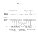
- FIG. 11 is a diagram for a further example of ACK/NACK transmission scheme according to a 1 st embodiment of the present invention. Particularly, FIG. 9 assumes a case that a repetition factor for a 1 st ACK/NACK transmission is set to 4 and that a repetition factor for a 2 nd ACK/NACK transmission is set to 3.
- ACK/NACK signal is transmitted in a 1 st ACK/NACK transmission in a manner of being repeated 4 times, 1 st and 2 nd subframes among the subframes included in the repetition interval are blocked subframes.
- ACK/NACK signal is transmitted in a 2 nd ACK/NACK transmission in a manner of being repeated 3 times, 1 st and 3 rd subframes among the subframes included in the repetition interval are blocked subframes.
- it is preferable that the ACK/NACK transmission is not performed in the blocked subframe in consideration of interference on another user equipment or relay node. And, counting of the ACK/NACK transmission is performed in a manner of including the blocked frame.
- ACK/NACK signal is transmitted in a non-blocked subframe behind the blocked subframe. For instance, instead of transmitting ACK/NACK signal repeatedly, the ACK/NACK signal is not transmitted in a blocked subframe but may be transmitted in a subframe shifted or delayed by N subframe(s). In this case, the N may be set to a negative number as well as to a positive number. If the N is set to the negative number, it means that the ACK/NACK signal is transmitted in a non-blocked subframe prior to a blocked subframe.
- the relay node is able to inform the R-UE of the N by upper layer signaling or physical layer signaling. If the N is set to 0, each of the R-UE and the relay node does not transmit ACK/NACK in a corresponding blocked subframe but is able to transmit ACK/NACK in a next non-blocked subframe closest to the corresponding blocked subframe.
- ACK/NACK signal supposed to be transmitted in a shifted or delayed subframe may be able to configure one signal in a manner of aggregated or combined with the shifted or delayed ACK/NACK signal.
- the aggregation or combination may be performed by one of ACK/NACK bundling, ACK/NACK multiplexing and the like or may use PUCCH format (e.g., PUCCH format 3, etc.) proposed by LTE-A.
- FIG. 12 is a diagram for one example of ACK/NACK transmission scheme according to a 2 nd embodiment of the present invention.
- a 1 st ACK/NACK transmission may be performed in a manner of being delayed by 1 subframe and a 2 nd ACK/NACK transmission may be performed in a manner of being delayed by N subframe(s).
- ACK/NACK signal supposed to be transmitted in the delayed subframe may be transmitted in a manner of being configured with a delayed ACK/NACK signal into one signal using one of ACK/NACK bundling, ACK/NACK multiplexing, PUCCH format (e.g., PUCCH format 3) proposed by LTE-A and the like.
- the above-described 1 st embodiment relates to an ACK/NACK repetition scheme as a method of solving the uplink ACK/NACK collision problem that may occur due to a blocked subframe between a backhaul link and an access link. Yet, when a repetition factor is set in a UL subframe corresponding to a UL ACK/NACK transmission timing point using the ACK/NACK repetition scheme, it may be inefficient to apply the same factor value to all UL subframes.
- ACK/NACK repetition factor set with reference to a backhaul UL subframe, in which UL ACK/NACK collision occurs is identically applied to a UL subframe free from the UL ACK/NACK collision, it may cause an unnecessary ACK/NACK repetition operation of R-UE (or RN).
- the present invention may propose the two kinds of methods in the following as a method of setting a different ACK/NACK repetition factor depending on a presence or non-presence of UL ACK/NACK collision in each UL subframe corresponding to a UL ACK/NACK transmission timing point.
- informations on an ACK/NACK repetition factor, a blocked subframe and a non-blocked subframe may be delivered to an R-UE (or a relay node) via an upper layer signal or a specific channel of a physical layer.
- R-UE or a relay node
- an ACK/NACK repletion factor is set different.
- the 3 rd embodiment of the present invention relates to a method of operating with an ACK/NACK repetition factor different in accordance with a blocked subframe or a non-blocked subframe, which belongs to a type of a UL subframe corresponding to a UL ACK/NACK transmission timing point.
- a method of counting the number of ACK/NACK repetitions each time a UL subframe appears irrespective of a blocked subframe or a non-blocked subframe, it is regarded as 1 repetition. And, the corresponding counting starts from a UL subframe corresponding to a current UL ACK/NACK transmission timing point.
- P 1 a + b
- the ACK/NACK repetition factor P 1 in a non-blocked subframe is set to a preset value (e.g., 0, 1, a negative value, etc.). In this case, it means that the ACK/NACK repetition scheme is not performed.
- the ACK/NACK repetition factor P1 of a blocked subframe may be set to a value other than the preset value. Based on this value, the ACK/NACK repetition scheme is performed.
- a method of setting ACK/NACK repetition factors P1 of blocked and non-blocked subframes may be defined in various ways other than the above-mentioned method.
- a different repetition factor may be set for each of the at least two blocked subframes.
- FIG. 13 is a diagram for one example of performing ACK/NACK repetition scheme according to a 3 rd embodiment of the present invention. Particularly, in case that a UL ACK/NACK transmission is requested in an access UL subframe #3 having an ACK/NACK repetition factor set to 3, FIG. 13 shows one example that an ACK/NACK repetition scheme is performed according to the 3 rd embodiment.
- an ACK/NACK transmission is not actually performed in a subframe #3 corresponding to a blocked subframe but the number of ACK/NACK repetitions is counted only.
- the ACK/NACK transmission of the access UL subframe #3 is actually performed two times in an access UL subframe #4 and an access UL subframe #1 of a next frame.
- an ACK/NACK repetition factor P1 in the ACK/NACK repetition performed non-blocked subframe is represented as 0.
- FIG. 14 is a diagram for another example of performing ACK/NACK repetition scheme according to a 3 rd embodiment of the present invention. Particularly, FIG. 14 shows one example that an ACK/NACK repetition scheme is performed in a TDD system according to the 3 rd embodiment.
- Un link and Uu link assume the UL-DL configuration #4.
- UL ACK/NACK collision occurs in a UL subframe #3.
- TDD UL-DL configuration #4 ACK/NACKs for the subframes #0, #1, #4 and #5 are transmitted in the subframe #2 and ACK/NACKs for the subframes #6, #7, #8 and #9 are transmitted in the subframe #3.
- the R-UE in case that an R-UE receives data in access DL subframes #6 and #7 from an RN, the R-UE should transmit ACK/NACK in an access UL subframe #3 of a next frame. Yet, since the ACK/NACK repetition factor of the subframe #3 is set to 2, the ACK/NACK transmission is actually performed in an access UL subframe #2 by the counting method according to the 3 rd embodiment. In particular, in the subframe #3 corresponding to a blocked subframe, ACK/NACK transmission is not actually performed but the number of ACK/NACK repetitions is counted only.
- the R-UE receives data from the RN in the access DL subframes #0, #1, #4 and #5
- FIG. 15 is a diagram for another example of performing ACK/NACK repetition scheme according to a 3 rd embodiment of the present invention. Particularly, FIG. 15 assumes a case that UL ACK/NACK collision occurs in UL subframe #2 in case of TDD UL-DL configuration #2.
- the RN should transmit ACK/NACK in an access UL subframe e#2 of a next frame in accordance with TDD UL-DL configuration #2. Yet, since the ACK/NACK repetition factor of the access UL subframe #2 is set to 2, the ACK/NACK transmission is performed in an access UL subframe #7 by the counting method according to the 3 rd embodiment. In particular, in the subframe #2 corresponding to a blocked subframe, ACK/NACK transmission is not actually performed but the number of ACK/NACK repetitions is counted only.
- the R-UE receives data in the access DL subframes #0, #1, #3 and #9, it is possible to perform ACK/NACK transmission in an access UL subframe #7 of a next frame in accordance with TDD UL-DL configuration #2.
- an ACK/NACK repetition factor is set different. Unlike the 3 rd embodiment, according to the 4 th embodiment, counting is performed only if an ACK/NACK transmission is actually performed in a non-blocked subframe except a blocked subframe. Alternatively, counting is performed each time a non-blocked subframe appears except a blocked subframe. Yet, an ACK/NACK repetition factor P 2 of a non-blocked subframe may be set to a preset value (e.g., 0, 1, negative value, etc.) like the 3 rd embodiment and is set to 0 in the following drawing.
- a preset value e.g., 0, 1, negative value, etc.
- a UL subframe corresponding to a current UL ACK/NACK transmission timing point is a non-blocked subframe, it is able to directly perform a UL ACK/NACK transmission in the corresponding subframe.
- the ACK/NACK repetition scheme may be construed as not operating.
- a method of disabling an ACK/NACK repetition scheme by designating an ACK/NACK repetition factor P 2 of a non-blocked subframe to a value other than a preset value is not excluded.
- a different repetition factor may be set for each of the at least two blocked subframes.
- FIG. 16 is a diagram for one example of performing ACK/NACK repetition scheme according to a 4 th embodiment of the present invention. Particularly, FIG. 13 assumes a case that a UL ACK/NACK transmission is requested in an access UL Subframe #3 having an ACK/NACK repetition factor set to 3 like FIG. 13 .
- a UL ACK/NACK transmission is actually performed total 3 times in access UL subframes $1, #1 and #4 actually for the access UL subframe #3 having the ACK/NACK repetition factor set to 3.
- the access UL subframe #4 having the same subframe index means a subframe of a different timing point actually having a time difference of 10 ms. If it is desired to obtain the same result of the case of applying the 1 st embodiment from the 4 th embodiment, the ACK/NACK repetition factor of the access UL subframe #3 is just modified into 2 from 3.
- FIG. 17 is a diagram for another example of performing ACK/NACK repetition scheme according to a 4 th embodiment of the present invention. Particularly, FIG. 17 shows one example of performing the ACK/NACK repetition scheme according to the 4 th embodiment in the TDD system shown in FIG. 14 .
- an ACK/NACK repetition factor is adjusted.
- the ACK/NACK repetition factor is adjusted into 1 from 2 in an access UL subframe #3.
- FIG. 18 is a diagram for a further example of performing ACK/NACK repetition scheme according to a 4 th embodiment of the present invention. Particularly, FIG. 18 shows one example of performing the ACK/NACK repetition scheme according to the 4 th embodiment in the TDD system shown in FIG. 15 .
- an ACK/NACK repetition factor is adjusted.
- the ACK/NACK repetition factor is adjusted into 1 from 2 in an access UL subframe #2.
- ACK/NACK repetition factor is set different depending on a presence or non-presence of UL ACK/NACK collision in each UL subframe corresponding to a UL ACK/NACK transmission timing point.
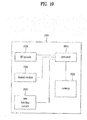
- FIG. 19 is a block diagram for one example of a communication device according to one embodiment of the present invention.
- a communication device 1900 includes a processor 1910, a memory 1920, an RF module 1930, a display module 1940 and a user interface module 1950.
- the communication device 1900 is illustrated for clarity and convenience of the description and some modules can be omitted. Moreover, the communication device 1900 is able to further include at least one necessary module. And, some modules of the communication device 1900 can be further divided into sub-modules.
- the processor 1910 is configured to perform operations according to the embodiment of the present invention exemplarily described with reference to the accompanying drawings. In particular, the detailed operations of the processor 1910 can refer to the contents described with reference to FIGs. 1 to 18 .
- the memory 1920 is connected to the processor 1910 and stores an operating system, applications, program codes, data and the like.
- the RF module 1930 is connected to the processor 1910 and performs a function of converting a baseband signal to a radio signal or converting a radio signal to a baseband signal. For this, the RF module 1930 performs analog conversion, amplification, filtering and frequency uplink transform or inverse processes thereof.
- the display module 1940 is connected to the processor 1910 and displays various kinds of informations.
- the display module 1940 can include such a well-known element as LCD (Liquid Crystal Display), LED (Light Emitting Diode), OLED (Organic Light Emitting Diode) and the like, by which the present invention is non-limited.
- the user interface module 1950 is connected to the processor 1910 and can include a combination of well-known interfaces including a keypad, a touchscreen and the like.
- a specific operation explained as performed by a base station can be performed by an upper node of the base station in some cases.
- various operations performed for communication with a terminal can be performed by a base station or other network nodes except the base station.
- 'base station' can be replaced by such a terminology as a fixed station, a Node B, an eNode B (eNB), an access point and the like.
- Embodiments of the present invention can be implemented using various means. For instance, embodiments of the present invention can be implemented using hardware, firmware, software and/or any combinations thereof. In case of the implementation by hardware, a method according to one embodiment of the present invention can be implemented by at least one selected from the group consisting of ASICs (application specific integrated circuits), DSPs (digital signal processors), DSPDs (digital signal processing devices), PLDs (programmable logic devices), FPGAs (field programmable gate arrays), processor, controller, microcontroller, microprocessor and the like.
- ASICs application specific integrated circuits
- DSPs digital signal processors
- DSPDs digital signal processing devices
- PLDs programmable logic devices
- FPGAs field programmable gate arrays
- processor controller, microcontroller, microprocessor and the like.
- a method according to each embodiment of the present invention can be implemented by modules, procedures, and/or functions for performing the above-explained functions or operations.
- Software code is stored in a memory unit and is then drivable by a processor.
- the memory unit is provided within or outside the processor to exchange data with the processor through the various means known in public.
Landscapes
- Engineering & Computer Science (AREA)
- Signal Processing (AREA)
- Computer Networks & Wireless Communication (AREA)
- Mobile Radio Communication Systems (AREA)
Applications Claiming Priority (2)
| Application Number | Priority Date | Filing Date | Title |
|---|---|---|---|
| US38019410P | 2010-09-03 | 2010-09-03 | |
| PCT/KR2011/006208 WO2012030097A2 (ko) | 2010-09-03 | 2011-08-23 | 무선 통신 시스템에서 단말이 릴레이 노드로 ack/nack 신호를 송신하는 방법 및 이를 위한 장치 |
Publications (2)
| Publication Number | Publication Date |
|---|---|
| EP2613467A2 true EP2613467A2 (de) | 2013-07-10 |
| EP2613467A4 EP2613467A4 (de) | 2017-11-08 |
Family
ID=45773352
Family Applications (1)
| Application Number | Title | Priority Date | Filing Date |
|---|---|---|---|
| EP11822072.2A Withdrawn EP2613467A4 (de) | 2010-09-03 | 2011-08-23 | Verfahren und vorrichtung für eine benutzervorrichtung zur übertragung von ack/nack-signalen an einen relais-knoten in einem drahtlosen kommunikationssystem |
Country Status (4)
| Country | Link |
|---|---|
| US (1) | US9119174B2 (de) |
| EP (1) | EP2613467A4 (de) |
| KR (1) | KR101838072B1 (de) |
| WO (1) | WO2012030097A2 (de) |
Families Citing this family (5)
| Publication number | Priority date | Publication date | Assignee | Title |
|---|---|---|---|---|
| WO2012157876A2 (ko) * | 2011-05-13 | 2012-11-22 | 엘지전자 주식회사 | 무선 통신 시스템에서 채널상태정보를 전송하는 방법 및 장치 |
| US9148173B2 (en) * | 2012-03-30 | 2015-09-29 | California Institute Of Technology | Distributed reed-solomon codes for simple multiple access networks |
| US11006462B2 (en) * | 2012-05-21 | 2021-05-11 | Blackberry Limited | System and method for handling of an uplink transmission collision with an ACK/NACK signal |
| KR101612667B1 (ko) | 2012-07-03 | 2016-04-14 | 엘지전자 주식회사 | 무선통신 시스템에서 상향링크 제어 채널을 위한 자원 할당 방법 및 장치 |
| WO2015114700A1 (ja) * | 2014-01-31 | 2015-08-06 | パナソニック インテレクチュアル プロパティ コーポレーション オブ アメリカ | 端末、基地局、送信方法及び受信方法 |
Family Cites Families (5)
| Publication number | Priority date | Publication date | Assignee | Title |
|---|---|---|---|---|
| JP2010541459A (ja) * | 2007-10-02 | 2010-12-24 | サムスン エレクトロニクス カンパニー リミテッド | 通信システムにおける信号の反復転送 |
| US9203564B2 (en) * | 2008-10-20 | 2015-12-01 | Qualcomm Incorporated | Data transmission via a relay station in a wireless communication system |
| WO2010090492A2 (ko) * | 2009-02-09 | 2010-08-12 | 엘지전자주식회사 | 상향링크 제어정보 전송 방법 및 장치 |
| US20100331037A1 (en) * | 2009-06-24 | 2010-12-30 | Yu-Chih Jen | Method and Related Communication Device for Enhancing Power Control Mechanism |
| CN102498688B (zh) * | 2009-09-18 | 2017-05-24 | 黑莓有限公司 | 用于上行链路多点协作信令的混合自动重复请求操作的方法和系统 |
-
2011
- 2011-08-23 US US13/819,483 patent/US9119174B2/en not_active Expired - Fee Related
- 2011-08-23 EP EP11822072.2A patent/EP2613467A4/de not_active Withdrawn
- 2011-08-23 KR KR1020137002568A patent/KR101838072B1/ko not_active Expired - Fee Related
- 2011-08-23 WO PCT/KR2011/006208 patent/WO2012030097A2/ko not_active Ceased
Non-Patent Citations (1)
| Title |
|---|
| See references of WO2012030097A2 * |
Also Published As
| Publication number | Publication date |
|---|---|
| US9119174B2 (en) | 2015-08-25 |
| EP2613467A4 (de) | 2017-11-08 |
| KR101838072B1 (ko) | 2018-03-13 |
| WO2012030097A2 (ko) | 2012-03-08 |
| WO2012030097A3 (ko) | 2012-04-26 |
| KR20130141431A (ko) | 2013-12-26 |
| US20130155942A1 (en) | 2013-06-20 |
Similar Documents
| Publication | Publication Date | Title |
|---|---|---|
| CN103380579B (zh) | 在应用了载波聚合方案的无线通信系统中配置回程链路子帧的方法及其设备 | |
| US9084246B2 (en) | Method for transmitting uplink control information in wireless communication system and apparatus therefor | |
| KR101792508B1 (ko) | 무선 통신 시스템에서 릴레이 노드를 위한 검색 영역 설정 방법 및 이를 위한 장치 | |
| KR101740445B1 (ko) | 무선 통신 시스템에서 릴레이 노드로 제어 채널을 송신하는 방법 및 이를 위한 장치 | |
| US9131494B2 (en) | Method for backhaul subframe setting between a base station and a relay node in a wireless communication system and a device therefor | |
| US9356680B2 (en) | Method of transceiving signal at relay node in wireless communication system and apparatus thereof | |
| US9350440B2 (en) | Method and apparatus for subset network coding with multiple antennas by relay node in wireless communication system | |
| EP2652886A2 (de) | Verfahren und vorrichtung zur übermittlung von kanalstatusinformation an eine makrobasisstation durch einen relaisknoten in einem drahtlosen kommunikationssystem mit trägeraggregation | |
| US9198094B2 (en) | Method for setting search space for handover of relay node in wireless communication system, and device therefor | |
| KR20140012641A (ko) | 무선 통신 시스템에서 동적 서브프레임 설정 방법 및 이를 위한 장치 | |
| KR20140034731A (ko) | 무선 통신 시스템에서 하향링크 제어 정보를 송수신하는 방법 및 이를 위한 장치 | |
| WO2012121509A2 (ko) | 반송파 집성 기법이 적용된 무선 통신 시스템에서 백홀 링크 서브프레임을 설정하는 방법 및 이를 위한 장치 | |
| US9750002B2 (en) | Method and apparatus for transmitting and receiving a signal through a relay node in a wireless communication system in which a carrier aggregation method is applied | |
| US9591664B2 (en) | Method for setting search space for relay node in wireless communication system and device therefor | |
| US9119174B2 (en) | Method and device for user equipment transmitting ACK/NACK signals to relay node in a wireless communication system | |
| US8824358B2 (en) | Method and apparatus for transmitting and receiving signals between a base station and a relay node in a wireless communication system | |
| US8989127B2 (en) | Method and device for relay node retransmitting backhaul uplink to base station in a wireless communication system |
Legal Events
| Date | Code | Title | Description |
|---|---|---|---|
| PUAI | Public reference made under article 153(3) epc to a published international application that has entered the european phase |
Free format text: ORIGINAL CODE: 0009012 |
|
| 17P | Request for examination filed |
Effective date: 20130306 |
|
| AK | Designated contracting states |
Kind code of ref document: A2 Designated state(s): AL AT BE BG CH CY CZ DE DK EE ES FI FR GB GR HR HU IE IS IT LI LT LU LV MC MK MT NL NO PL PT RO RS SE SI SK SM TR |
|
| DAX | Request for extension of the european patent (deleted) | ||
| A4 | Supplementary search report drawn up and despatched |
Effective date: 20171006 |
|
| RIC1 | Information provided on ipc code assigned before grant |
Ipc: H04L 1/00 20060101ALI20170929BHEP Ipc: H04L 1/18 20060101AFI20170929BHEP Ipc: H04B 7/14 20060101ALI20170929BHEP Ipc: H04J 11/00 20060101ALI20170929BHEP |
|
| STAA | Information on the status of an ep patent application or granted ep patent |
Free format text: STATUS: EXAMINATION IS IN PROGRESS |
|
| 17Q | First examination report despatched |
Effective date: 20201023 |
|
| STAA | Information on the status of an ep patent application or granted ep patent |
Free format text: STATUS: THE APPLICATION IS DEEMED TO BE WITHDRAWN |
|
| 18D | Application deemed to be withdrawn |
Effective date: 20231011 |