EP2614764A2 - Echangeur de chaleur d'eaux usées pour lave-vaisselle ainsi que lave-vaisselle - Google Patents
Echangeur de chaleur d'eaux usées pour lave-vaisselle ainsi que lave-vaisselle Download PDFInfo
- Publication number
- EP2614764A2 EP2614764A2 EP13150953.1A EP13150953A EP2614764A2 EP 2614764 A2 EP2614764 A2 EP 2614764A2 EP 13150953 A EP13150953 A EP 13150953A EP 2614764 A2 EP2614764 A2 EP 2614764A2
- Authority
- EP
- European Patent Office
- Prior art keywords
- channel
- plates
- heat transfer
- heat exchanger
- plate
- Prior art date
- Legal status (The legal status is an assumption and is not a legal conclusion. Google has not performed a legal analysis and makes no representation as to the accuracy of the status listed.)
- Withdrawn
Links
- 239000002351 wastewater Substances 0.000 title claims description 72
- 239000004033 plastic Substances 0.000 claims abstract description 29
- 229920003023 plastic Polymers 0.000 claims abstract description 29
- 239000000463 material Substances 0.000 claims abstract description 19
- 239000007769 metal material Substances 0.000 claims abstract description 5
- 238000000465 moulding Methods 0.000 claims description 68
- 239000000654 additive Substances 0.000 claims description 9
- RYGMFSIKBFXOCR-UHFFFAOYSA-N Copper Chemical compound [Cu] RYGMFSIKBFXOCR-UHFFFAOYSA-N 0.000 claims description 3
- 239000010949 copper Substances 0.000 claims description 3
- 229910052802 copper Inorganic materials 0.000 claims description 3
- 238000001746 injection moulding Methods 0.000 claims description 3
- 239000010935 stainless steel Substances 0.000 claims description 3
- 229910001220 stainless steel Inorganic materials 0.000 claims description 3
- 239000013505 freshwater Substances 0.000 description 15
- 239000004743 Polypropylene Substances 0.000 description 8
- 229920001155 polypropylene Polymers 0.000 description 8
- 239000004952 Polyamide Substances 0.000 description 6
- 239000012530 fluid Substances 0.000 description 6
- 229920002647 polyamide Polymers 0.000 description 6
- 239000002918 waste heat Substances 0.000 description 4
- 238000010276 construction Methods 0.000 description 3
- 229910052751 metal Inorganic materials 0.000 description 3
- 239000002184 metal Substances 0.000 description 3
- -1 polypropylene Polymers 0.000 description 3
- 229910045601 alloy Inorganic materials 0.000 description 2
- 239000000956 alloy Substances 0.000 description 2
- 229910052582 BN Inorganic materials 0.000 description 1
- PZNSFCLAULLKQX-UHFFFAOYSA-N Boron nitride Chemical compound N#B PZNSFCLAULLKQX-UHFFFAOYSA-N 0.000 description 1
- OKTJSMMVPCPJKN-UHFFFAOYSA-N Carbon Chemical compound [C] OKTJSMMVPCPJKN-UHFFFAOYSA-N 0.000 description 1
- 240000006829 Ficus sundaica Species 0.000 description 1
- 229920000426 Microplastic Polymers 0.000 description 1
- 230000000996 additive effect Effects 0.000 description 1
- 230000015572 biosynthetic process Effects 0.000 description 1
- PMHQVHHXPFUNSP-UHFFFAOYSA-M copper(1+);methylsulfanylmethane;bromide Chemical compound Br[Cu].CSC PMHQVHHXPFUNSP-UHFFFAOYSA-M 0.000 description 1
- 238000004851 dishwashing Methods 0.000 description 1
- 229920001971 elastomer Polymers 0.000 description 1
- 239000000806 elastomer Substances 0.000 description 1
- 230000009969 flowable effect Effects 0.000 description 1
- 229910002804 graphite Inorganic materials 0.000 description 1
- 239000010439 graphite Substances 0.000 description 1
- CPLXHLVBOLITMK-UHFFFAOYSA-N magnesium oxide Inorganic materials [Mg]=O CPLXHLVBOLITMK-UHFFFAOYSA-N 0.000 description 1
- 239000000395 magnesium oxide Substances 0.000 description 1
- AXZKOIWUVFPNLO-UHFFFAOYSA-N magnesium;oxygen(2-) Chemical compound [O-2].[Mg+2] AXZKOIWUVFPNLO-UHFFFAOYSA-N 0.000 description 1
- 238000004519 manufacturing process Methods 0.000 description 1
- 150000002739 metals Chemical class 0.000 description 1
- TWNQGVIAIRXVLR-UHFFFAOYSA-N oxo(oxoalumanyloxy)alumane Chemical compound O=[Al]O[Al]=O TWNQGVIAIRXVLR-UHFFFAOYSA-N 0.000 description 1
- 230000002093 peripheral effect Effects 0.000 description 1
- 239000008237 rinsing water Substances 0.000 description 1
- 239000010865 sewage Substances 0.000 description 1
- 230000035939 shock Effects 0.000 description 1
- 238000005507 spraying Methods 0.000 description 1
- 238000003856 thermoforming Methods 0.000 description 1
- 229920001169 thermoplastic Polymers 0.000 description 1
- 229920002725 thermoplastic elastomer Polymers 0.000 description 1
- 229920001187 thermosetting polymer Polymers 0.000 description 1
- 239000004416 thermosoftening plastic Substances 0.000 description 1
Images


Classifications
-
- A—HUMAN NECESSITIES
- A47—FURNITURE; DOMESTIC ARTICLES OR APPLIANCES; COFFEE MILLS; SPICE MILLS; SUCTION CLEANERS IN GENERAL
- A47L—DOMESTIC WASHING OR CLEANING; SUCTION CLEANERS IN GENERAL
- A47L15/00—Washing or rinsing machines for crockery or tableware
- A47L15/42—Details
- A47L15/4291—Recovery arrangements, e.g. for the recovery of energy or water
-
- F—MECHANICAL ENGINEERING; LIGHTING; HEATING; WEAPONS; BLASTING
- F28—HEAT EXCHANGE IN GENERAL
- F28D—HEAT-EXCHANGE APPARATUS, NOT PROVIDED FOR IN ANOTHER SUBCLASS, IN WHICH THE HEAT-EXCHANGE MEDIA DO NOT COME INTO DIRECT CONTACT
- F28D21/00—Heat-exchange apparatus not covered by any of the groups F28D1/00 - F28D20/00
- F28D21/0001—Recuperative heat exchangers
- F28D21/0012—Recuperative heat exchangers the heat being recuperated from waste water or from condensates
-
- F—MECHANICAL ENGINEERING; LIGHTING; HEATING; WEAPONS; BLASTING
- F28—HEAT EXCHANGE IN GENERAL
- F28D—HEAT-EXCHANGE APPARATUS, NOT PROVIDED FOR IN ANOTHER SUBCLASS, IN WHICH THE HEAT-EXCHANGE MEDIA DO NOT COME INTO DIRECT CONTACT
- F28D9/00—Heat-exchange apparatus having stationary plate-like or laminated conduit assemblies for both heat-exchange media, the media being in contact with different sides of a conduit wall
- F28D9/0031—Heat-exchange apparatus having stationary plate-like or laminated conduit assemblies for both heat-exchange media, the media being in contact with different sides of a conduit wall the conduits for one heat-exchange medium being formed by paired plates touching each other
- F28D9/0037—Heat-exchange apparatus having stationary plate-like or laminated conduit assemblies for both heat-exchange media, the media being in contact with different sides of a conduit wall the conduits for one heat-exchange medium being formed by paired plates touching each other the conduits for the other heat-exchange medium also being formed by paired plates touching each other
-
- F—MECHANICAL ENGINEERING; LIGHTING; HEATING; WEAPONS; BLASTING
- F28—HEAT EXCHANGE IN GENERAL
- F28F—DETAILS OF HEAT-EXCHANGE AND HEAT-TRANSFER APPARATUS, OF GENERAL APPLICATION
- F28F21/00—Constructions of heat-exchange apparatus characterised by the selection of particular materials
- F28F21/06—Constructions of heat-exchange apparatus characterised by the selection of particular materials of plastics material
- F28F21/065—Constructions of heat-exchange apparatus characterised by the selection of particular materials of plastics material the heat-exchange apparatus employing plate-like or laminated conduits
-
- A—HUMAN NECESSITIES
- A47—FURNITURE; DOMESTIC ARTICLES OR APPLIANCES; COFFEE MILLS; SPICE MILLS; SUCTION CLEANERS IN GENERAL
- A47L—DOMESTIC WASHING OR CLEANING; SUCTION CLEANERS IN GENERAL
- A47L15/00—Washing or rinsing machines for crockery or tableware
- A47L15/42—Details
- A47L15/4214—Water supply, recirculation or discharge arrangements; Devices therefor
Definitions
- the present invention relates to a waste water heat exchanger for dishwashers, in particular for commercial dishwashers, and a dishwasher with such a waste water heat exchanger.
- Claims 2 to 8 each relate to advantageous embodiments of the wastewater heat exchanger according to the invention for dishwashers.
- the wastewater heat exchanger comprises at least two channel molding plates and at least one heat transfer plate.
- the at least two channel molding plates are made of a plastic material, while the heat transfer plate of a metallic material or a thermally conductive plastic material, in particular a plastic, the additives, in particular metallic additives, are added.
- a thermally conductive plastic or a plastic with increased thermal conductivity in the context of this invention comprises in particular plastics with a thermal conductivity of 1.0 W / (m * K) to 10 W / (m * k), preferably plastics with thermal conductivities of 5.0 W / (m * K) to 10 W / (m * K).
- PP polypropylene
- the thermal conductivity of PP, PA (polyamide) or similar plastics is normally about 0.2 W / (m * K).
- additives such as aluminum oxide, magnesium oxide, graphite, aluminum nitride or boron nitride, significantly higher values can be achieved.
- An additive is added to the plastic granules prior to processing (spraying). Thermal conductivities of 1, 0 (W / (m * K) to 10 W / (m * K) are achieved, which means an increase of the thermal conductivity by a factor of 5 to 50 compared to normal PP.
- metal material for the purposes of this invention includes all metals, semimetals and alloys and intermetallic phases, as well as materials that undergo a metallic bond. Such materials are characterized by a high thermal conductivity.
- plastic material includes, inter alia, materials whose basic component is synthetically or semi-synthetically prepared from monomeric organic molecules.
- plastic material in the context of this invention includes in particular thermoplastics, thermosets, elastomers and thermoplastic elastomers.
- a channel molding plate has on at least one side of the channel molding plate on one side open, in particular continuously extending channel, which preferably extends from an outer region or edge region of the channel molding plate in an inner region and from there again in an outer region or edge region of the channel molding plate.
- the channel has an inlet opening at one end and an outlet opening at its other end, so that a flowable medium, in particular fresh water on the one hand and sewage on the other hand, can be introduced into the channel at the inlet opening, through the channel and through the outlet opening can be discharged again.
- Channel molding plates which form a channel on both sides
- channel molding plates which form a channel on both sides
- these channel molding plates are then used in an inner region of the wastewater heat exchanger or as intermediate plates.
- Channel molding plates with a channel on only one side are used as so-called end plates, which include the above-mentioned intermediate plates in a sandwich construction, especially in smaller-dimensioned wastewater heat exchangers or even larger-sized wastewater heat exchangers.
- the channel molding plates and the heat transfer plate (s) are arranged such that the open side of a channel of a first channel molding plate faces the open side of a channel of a second thermoforming plate, the open side of the two channels being disposed through a heat transfer plate disposed between the two channel molding plates is, are separated from each other.
- the open on one side channels of the channel molding plates are therefore completed by the heat transfer plate.
- a wastewater heat exchanger By a wastewater heat exchanger according to the present invention, therefore, two channels are realized, a channel for a first fluid, typically fresh water, and a channel for a second fluid, typically wastewater, these two channels being very close to each other and these two channels passing through the heat transfer plate , which is very good thermal conductivity, are separated from each other.
- a first fluid typically fresh water
- a second fluid typically wastewater
- the wastewater heat exchanger of the present invention has the particular advantage that it can be made very cost-effective, on the other hand, it has the advantage that the channel molding plates on the one hand and the heat transfer plate or the heat transfer plates on the other hand, both in terms of their structure and in terms of their Material selection can be optimally adapted to their desired function.
- the channel molding plates form the structures that are required for the formation of the channels, and they must therefore have a certain dimensional stability and thus a certain material thickness.
- the channel molding plates are therefore made according to the invention of plastic, since it is a relatively light material in plastic, even at thicker wall thicknesses, cost, preferably by injection molding, can be produced without the total weight is too large, while the thermal conductivity due the structure of the invention need not be considered.
- the heat transfer plate or the heat transfer plates made of a metallic material or a thermally conductive plastic or a plastic with increased thermal conductivity, in particular a plastic with metallic additives, so that a very high thermal conductivity is provided.
- This is particularly advantageous because heat transfer from one channel to another channel occurs through this heat transfer plate and only to a lesser extent through the channel die plates which, due to their plastic material and the required thickness of the material to provide the dimensional stability noted above, have lower thermal conductivity exhibit.
- the heat transfer plates need not have any inherent dimensional stability, but merely constitute a separating layer between the channels formed by the channel molding plates, these heat transfer plates can be made very thin, so that both costs As well as weight are minimized, at the same time a maximum thermal conductivity and thus a maximum efficiency of the heat exchanger is provided.
- the particular structure and construction of the wastewater heat exchanger according to the invention therefore lead to optimal results in terms of the exchange of heat between two fluids, wastewater and fresh water, at the same time costs and weight are kept very low.
- the channel molding plates are formed so that a substantially spiral-shaped channel is formed, wherein the spiral shape may be formed nearly circular, but may also have a more straight or oval shape. It is particularly preferred to change the curvature of the spiral as evenly as possible and in particular to provide no edges or corners in the channels, as this may hinder the flow of fluids, wastewater and fresh water.
- the shape of the spiral channels as a double spiral, can be adapted in particular to the cross-sectional shape of the channel plate or the heat transfer plates, both substantially circular or oval channel plates and heat transfer plates can be provided, or even rectangular cross-sectional shapes can be provided, in particular with rounded Corners.
- the overall shape of the wastewater heat exchanger can be adapted in many areas to the requirements of the dishwasher.
- a particularly preferred wastewater heat exchanger comprises two channel molding plates which form a channel on its two sides, that is to say on the front side and the rear side, and two channel molding plates which form a channel on only one side. Furthermore, such a particularly preferred wastewater heat exchanger comprises a total of three heat transfer plates.
- the channel molding plates and the heat transfer plates are arranged so that a total of three pairs of opposing channels are formed, wherein the opposite channels of each pair are separated by a heat transfer plate.
- the channel molding plates and the heat transfer plates are arranged so that a fluid first passes through a channel in a first channel plate shape, then a channel in a second channel plate and finally a channel in a third channel plate form, for both fluids, so the waste water and the fresh water , applies.
- waste water heat exchanger with only one channel molding plate, which forms a channel on both sides, and two channel molding plates, which form a channel only on one side. Further, it is also possible to provide waste heat exchangers having three or more channel molding plates which form a channel on both sides to further increase the heat exchange performance of the wastewater heat exchanger.
- the wastewater heat exchanger of the present invention is therefore modular in design and, with very few, different components, can be adapted or extended very flexibly, which is a further advantage of the wastewater heat exchanger according to the present invention.
- the heat transfer plate or the heat transfer plates always in an interior are arranged, so basically surrounded on both sides of channel molding plates, which give a necessary shape structure and protect the heat transfer plates from possible shocks and damage from the outside.
- the channel molding plates and the heat transfer plates are glued together, in particular pressed and glued, which allows a particularly simple and therefore cost-effective production.
- the plates can, for example, be welded, if all plates are made of plastic.
- the channel molding plates are preferably produced in an injection molding process, wherein as a material in particular polypropylene (PP), polyamide (PA) or similar materials are suitable.
- PP polypropylene
- PA polyamide
- Suitable materials for the heat transfer plates are materials with higher conductivity than PP or PA, in particular copper, stainless steel or plastics with conductivity-increasing additives, which have a very high thermal conductivity, or even alloys.
- the heat transfer plates can be made very thin, preferably the heat transfer plates have a thickness of 0.1 mm to 1.5 mm, more preferably from 0.2 mm to 0.8 mm, further preferably 0.4 mm to 0.6 mm and in particular from 0.2 mm to 0.4 mm.
- the invention further relates to a dishwasher, in particular a commercial dishwasher, with a waste water heat exchanger, as has been described above.
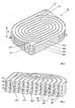
- Fig. 1 shows a perspective view of an embodiment of a wastewater heat exchanger 10 according to the invention, comprising a total of four channel molding plates 102, 104, 106 and 108. Between the channel molding plates 102, 104, 106 and 108 a total of three heat transfer plates 203, 205 and 207 are arranged, the heat transfer plate 203 between the channel molding plates 102 and 104, the heat transfer plate 205 between the channel molding plates 104 and 106, and the heat transfer plate 207 between the channel molding plates 106 and 108th
- the channel molding plates 102, 104, 106 and 108 are shaped to form a one-side open channel extending continuously and substantially spirally from an outer region or edge region of the channel molding plate 102, 104, 106, 108 into an interior region and from there again into an outer region or edge region of the channel molding plate 102, 104, 106, 108 extends.
- the open sides of the channels are closed by the heat transfer plates 203, 205 and 207, so that closed channels arise.
- the wastewater heat exchanger 10 has an inlet opening F1 for the introduction of fresh water.
- the fresh water introduced through the inlet port F1 is first led into the channel 322 formed by the channel forming plate 106 and the heat transfer plate 207.
- the fresh water then flows through the channel 324 formed by the channel molding plate 104 and the heat transfer plate 205.
- the fresh water is passed through the channel 326, which is formed by the channel plate 102 and the heat transfer plate 203.
- the fresh water is finally removed again at an outlet opening F2.
- the waste water heat exchanger 10 includes an inlet port A1 for the waste water.
- the waste water first flows through the channel 342 formed by the channel forming plate 104 and the heat transfer plate 203, subsequently through the channel 344 formed by the channel forming plate 106 and the heat transfer plate 205, and finally through the channel 346 passing through the channel forming plate 108 and the heat transfer plate 207 is formed.
- the wastewater is removed at an outlet A2 the wastewater heat exchanger.
- the channel molding plates 102, 104, 106 and 108 and the heat transfer plates 203, 205 and 207 and the inlets A1, F1 and the outlets A2, F2 are designed so that wastewater and fresh water in opposite channels in opposite directions and in directly adjacent Run channels and wastewater and fresh water and the entire wastewater heat exchanger in opposite directions, through the different levels of the channels, ie also in the vertical direction V (s. Fig. 1 ), so that fresh water, which has just been introduced through the inlet F1, flows in a channel region 322 which opposes a channel region 346 in which Wastewater is located, which has already passed through almost the entire wastewater heat exchanger. The same applies vice versa for wastewater that is being led through the inlet A1 into the wastewater heat exchanger.
- the channel molding plates 102, 104, 106 and 108 are made of PP or PA in this embodiment, while the heat transfer plates 203, 205 and 207 are made of plastic in this embodiment, wherein the plastic is provided with additives that increase the thermal conductivity.
- the heat transfer plates can also be made of metal, for example, copper.
- Fig. 3 shows an embodiment of a heat transfer plate 200, which is formed very similar to the heat transfer plates, which in the Figures 1 and 2 Therefore, identical reference numerals are used for these similar elements.
- heat transfer plate 200 is a heat transfer plate made of stainless steel, which has a thickness of 0.3 mm. Again, it is of course possible that alternatively a heat transfer plate made of plastic with thermal conductivity increasing additives is used.
- the heat transfer plate 200 has two openings 220 and 240, can pass through the wastewater or fresh water to pass through all the channel formed by the channel molding plates and the heat transfer plates channel or channels of the wastewater heat exchanger.
- Fig. 4 shows an embodiment of a channel molding plate 104, which in the Figures 1 and 2 shown channel molding plate 104 is very similar, so that identical reference numerals are used.
- Channel plate shown is a mold plate, which forms on both sides each one open on one side channel, wherein in the perspective view of Fig. 4 only the channel 342 is visible on one side.
- channel molding plate 104 is therefore a channel molding plate, which in a multi-layer wastewater heat exchanger, such as in Fig. 1 and Fig. 2 is shown, and is used there in an indoor area.
- Fig. 5 shows a perspective view of another channel molding plate 108, which in the Figs. 1 and 2 shown channel plate 108 is very similar and can also be used in a multi-layer wastewater heat exchanger.
- a channel molding plate 108 is such a channel molding plate, in which only one side of a channel 346 is formed.
- channel plate 108 is therefore suitable both for a multi-layer wastewater heat exchanger, as in the Fig. 1 and 2 is shown, in this case, for a channel molding plate, which is used in a peripheral region of the waste water heat exchanger as the end plate, also suitable in Fig. 5 also shown channel plate for a smaller wastewater heat exchanger, for example, consists of only two channel plates, which are separated by a heat transfer plate.
Landscapes
- Engineering & Computer Science (AREA)
- Physics & Mathematics (AREA)
- Thermal Sciences (AREA)
- Mechanical Engineering (AREA)
- General Engineering & Computer Science (AREA)
- Heat-Exchange Devices With Radiators And Conduit Assemblies (AREA)
Applications Claiming Priority (1)
| Application Number | Priority Date | Filing Date | Title |
|---|---|---|---|
| DE102012000455 | 2012-01-12 |
Publications (2)
| Publication Number | Publication Date |
|---|---|
| EP2614764A2 true EP2614764A2 (fr) | 2013-07-17 |
| EP2614764A3 EP2614764A3 (fr) | 2017-03-29 |
Family
ID=47623921
Family Applications (1)
| Application Number | Title | Priority Date | Filing Date |
|---|---|---|---|
| EP13150953.1A Withdrawn EP2614764A3 (fr) | 2012-01-12 | 2013-01-11 | Echangeur de chaleur d'eaux usées pour lave-vaisselle ainsi que lave-vaisselle |
Country Status (1)
| Country | Link |
|---|---|
| EP (1) | EP2614764A3 (fr) |
Cited By (9)
| Publication number | Priority date | Publication date | Assignee | Title |
|---|---|---|---|---|
| US9289107B2 (en) | 2011-12-13 | 2016-03-22 | Ecolab Usa Inc. | Dishmachine |
| WO2016048945A1 (fr) * | 2014-09-22 | 2016-03-31 | Illinois Tool Works Inc. | Lave-vaisselle avec système de thermorégulation d'eau de vidange avec récupération d'énergie utilisant des échangeurs à plaques |
| EP3074710A4 (fr) * | 2013-11-29 | 2017-08-23 | Limited Cyclotec | Échangeur de chaleur |
| WO2017150975A1 (fr) * | 2016-03-01 | 2017-09-08 | Level Holding B.V. | Récupérateur, dont certaines parties sont fabriquées par moulage par injection |
| US10610081B2 (en) | 2014-09-02 | 2020-04-07 | Illinois Tool Works Inc. | Dishwasher having a liquid transportation line |
| EP3988884A1 (fr) * | 2020-10-20 | 2022-04-27 | Haier Deutschland GmbH | Lave-vaisselle |
| WO2022180151A1 (fr) * | 2021-02-25 | 2022-09-01 | Dutch Innovation In Air Treatment Bv | Procédé de fabrication d'un empilement interrelié de cadres thermoplastiques |
| EP4261487A1 (fr) | 2022-04-13 | 2023-10-18 | HAIER Germany GmbH | Unité d'échangeur de chaleur, dispositif échangeur de chaleur, lave-vaisselle, machine à laver et procédé de fabrication d'une unité d'échangeur de chaleur |
| WO2024041071A1 (fr) * | 2022-08-23 | 2024-02-29 | 佛山市顺德区美的洗涤电器制造有限公司 | Lave-vaisselle |
Citations (1)
| Publication number | Priority date | Publication date | Assignee | Title |
|---|---|---|---|---|
| EP0689791A1 (fr) | 1994-06-28 | 1996-01-03 | Premark Feg Corporation | Machine à rincer et dispositif de récupération de chaleur des eaux usées |
Family Cites Families (4)
| Publication number | Priority date | Publication date | Assignee | Title |
|---|---|---|---|---|
| GB655470A (en) * | 1948-03-08 | 1951-07-25 | Raymond Ernest Wigg | Improvements in or relating to heat exchangers |
| EP0982427B1 (fr) * | 1998-08-25 | 2003-03-05 | Joma-Polytec Kunststofftechnik GmbH | Echangeur de chaleur à courants croisés pour sèche-linge avec condenseur |
| DE10359573A1 (de) * | 2003-12-18 | 2005-07-28 | Robert Bosch Gmbh | Wärmeübertragungseinheit für einen Wärmetauscher |
| DE102009032370A1 (de) * | 2009-07-08 | 2011-01-13 | Sartorius Stedim Biotech Gmbh | Plattenwärmetauscher |
-
2013
- 2013-01-11 EP EP13150953.1A patent/EP2614764A3/fr not_active Withdrawn
Patent Citations (1)
| Publication number | Priority date | Publication date | Assignee | Title |
|---|---|---|---|---|
| EP0689791A1 (fr) | 1994-06-28 | 1996-01-03 | Premark Feg Corporation | Machine à rincer et dispositif de récupération de chaleur des eaux usées |
Cited By (19)
| Publication number | Priority date | Publication date | Assignee | Title |
|---|---|---|---|---|
| US9289107B2 (en) | 2011-12-13 | 2016-03-22 | Ecolab Usa Inc. | Dishmachine |
| US11191419B2 (en) | 2011-12-13 | 2021-12-07 | Ecolab Usa Inc. | Dishmachine |
| US10314461B2 (en) | 2011-12-13 | 2019-06-11 | Ecolab Usa Inc. | Dishmachine |
| US10349803B2 (en) | 2011-12-13 | 2019-07-16 | Ecolab Usa Inc. | Dishmachine |
| EP3074710A4 (fr) * | 2013-11-29 | 2017-08-23 | Limited Cyclotec | Échangeur de chaleur |
| US10610081B2 (en) | 2014-09-02 | 2020-04-07 | Illinois Tool Works Inc. | Dishwasher having a liquid transportation line |
| WO2016048945A1 (fr) * | 2014-09-22 | 2016-03-31 | Illinois Tool Works Inc. | Lave-vaisselle avec système de thermorégulation d'eau de vidange avec récupération d'énergie utilisant des échangeurs à plaques |
| CN106714645A (zh) * | 2014-09-22 | 2017-05-24 | 伊利诺斯工具制品有限公司 | 具有使用板式热交换器进行能量回收的废水调温系统的器皿洗涤机 |
| US9986886B2 (en) | 2014-09-22 | 2018-06-05 | Illinois Tool Works Inc. | Warewasher with drain water tempering system with energy recovery using plate heat exchangers |
| WO2017150975A1 (fr) * | 2016-03-01 | 2017-09-08 | Level Holding B.V. | Récupérateur, dont certaines parties sont fabriquées par moulage par injection |
| NL2016347B1 (nl) * | 2016-03-01 | 2017-09-11 | Level Holding Bv | Recuperator, waarvan delen zijn vervaardigd door spuitgieten. |
| EP3988884A1 (fr) * | 2020-10-20 | 2022-04-27 | Haier Deutschland GmbH | Lave-vaisselle |
| WO2022084279A1 (fr) * | 2020-10-20 | 2022-04-28 | Haier Deutschland GmbH | Lave-vaisselle |
| CN116490741A (zh) * | 2020-10-20 | 2023-07-25 | 海尔德国股份有限公司 | 洗碗机 |
| WO2022180151A1 (fr) * | 2021-02-25 | 2022-09-01 | Dutch Innovation In Air Treatment Bv | Procédé de fabrication d'un empilement interrelié de cadres thermoplastiques |
| NL2027649A (en) * | 2021-02-25 | 2022-09-20 | Dutch Innovation In Air Treat B V | Process to manufacture an interconnected stack of thermoplastic frames |
| EP4261487A1 (fr) | 2022-04-13 | 2023-10-18 | HAIER Germany GmbH | Unité d'échangeur de chaleur, dispositif échangeur de chaleur, lave-vaisselle, machine à laver et procédé de fabrication d'une unité d'échangeur de chaleur |
| WO2023198446A1 (fr) | 2022-04-13 | 2023-10-19 | Haier Germany Gmbh | Unité d'échangeur de chaleur, dispositif d'échangeur de chaleur, lave-vaisselle, machine à laver et processus de fabrication d'une unité d'échangeur de chaleur |
| WO2024041071A1 (fr) * | 2022-08-23 | 2024-02-29 | 佛山市顺德区美的洗涤电器制造有限公司 | Lave-vaisselle |
Also Published As
| Publication number | Publication date |
|---|---|
| EP2614764A3 (fr) | 2017-03-29 |
Similar Documents
| Publication | Publication Date | Title |
|---|---|---|
| EP2614764A2 (fr) | Echangeur de chaleur d'eaux usées pour lave-vaisselle ainsi que lave-vaisselle | |
| EP1559980B1 (fr) | Echangeur de chaleur à plaques | |
| EP3163242B1 (fr) | Indirekter ladeluftkühler | |
| DE102007005370A1 (de) | Wärmetauscher | |
| DE202008004582U1 (de) | Plattenwärmetauscher | |
| DE102010063141A1 (de) | Wärmetauscher | |
| DE102007011762A1 (de) | Wärmetauscher, insbesondere Ölkühler für Kraftfahrzeuge | |
| DE102012217871A1 (de) | Wärmeübertrager | |
| DE2923944A1 (de) | Plattenwaermetauscher | |
| DE3141161A1 (de) | Plattenwaermeaustauscher | |
| DE112010002307T5 (de) | Kühlkörper | |
| DE102017214822A1 (de) | Wärmeübertrager | |
| DE10061949A1 (de) | Abgas-Wärmetauscher | |
| DE102018207640A1 (de) | Kühlstruktur | |
| DE202017102436U1 (de) | Wärmetauscher mit Mikrokanal-Struktur oder Flügelrohr-Struktur | |
| DE102017219433A1 (de) | Wärmeübertrager für einen Verbrennungsmotor | |
| DE202017104743U1 (de) | Wärmetauscher mit Mikrokanal-Struktur oder Flügelrohr-Struktur | |
| DE102015115261A1 (de) | Kühleinrichtung mit einem Flüssigkeitskühlkörper | |
| EP1687579B1 (fr) | Refroidisseur d'air de suralimentation/d'agent refrigerant | |
| DE102009014936A1 (de) | Abwasserrohr mit einer Frischwasserleiteinrichtung sowie Wärmeübertrager | |
| DE2119872A1 (de) | Leitplatte für Mantel und Rohr wärmeaustauscher | |
| DE102006053702B4 (de) | Wärmetauscher, insbesondere Gaskühler | |
| EP2167895A1 (fr) | Échangeur de chaleur | |
| DE102019118834A1 (de) | Fluiddurchströmter Kühlkörper | |
| DE112015003901B4 (de) | Sammelkammer für einen Wärmetauscher, Verbindungssystem und Wärmetauscher |
Legal Events
| Date | Code | Title | Description |
|---|---|---|---|
| PUAI | Public reference made under article 153(3) epc to a published international application that has entered the european phase |
Free format text: ORIGINAL CODE: 0009012 |
|
| AK | Designated contracting states |
Kind code of ref document: A2 Designated state(s): AL AT BE BG CH CY CZ DE DK EE ES FI FR GB GR HR HU IE IS IT LI LT LU LV MC MK MT NL NO PL PT RO RS SE SI SK SM TR |
|
| AX | Request for extension of the european patent |
Extension state: BA ME |
|
| PUAL | Search report despatched |
Free format text: ORIGINAL CODE: 0009013 |
|
| AK | Designated contracting states |
Kind code of ref document: A3 Designated state(s): AL AT BE BG CH CY CZ DE DK EE ES FI FR GB GR HR HU IE IS IT LI LT LU LV MC MK MT NL NO PL PT RO RS SE SI SK SM TR |
|
| AX | Request for extension of the european patent |
Extension state: BA ME |
|
| RIC1 | Information provided on ipc code assigned before grant |
Ipc: F28D 21/00 20060101ALI20170223BHEP Ipc: F28D 9/00 20060101ALI20170223BHEP Ipc: F28F 21/06 20060101ALI20170223BHEP Ipc: A47L 15/42 20060101AFI20170223BHEP |
|
| STAA | Information on the status of an ep patent application or granted ep patent |
Free format text: STATUS: THE APPLICATION HAS BEEN WITHDRAWN |
|
| 18W | Application withdrawn |
Effective date: 20170531 |