EP2615518B1 - Procédé de mise en temperature et de régulation de la température d'un outil de fabrication chauffé par un fluide en phase liquide et/ou vapeur - Google Patents
Procédé de mise en temperature et de régulation de la température d'un outil de fabrication chauffé par un fluide en phase liquide et/ou vapeur Download PDFInfo
- Publication number
- EP2615518B1 EP2615518B1 EP13151134.7A EP13151134A EP2615518B1 EP 2615518 B1 EP2615518 B1 EP 2615518B1 EP 13151134 A EP13151134 A EP 13151134A EP 2615518 B1 EP2615518 B1 EP 2615518B1
- Authority
- EP
- European Patent Office
- Prior art keywords
- time
- heat
- temperature
- duration
- heating
- Prior art date
- Legal status (The legal status is an assumption and is not a legal conclusion. Google has not performed a legal analysis and makes no representation as to the accuracy of the status listed.)
- Not-in-force
Links
- 238000010438 heat treatment Methods 0.000 title claims description 214
- 238000000034 method Methods 0.000 title claims description 54
- 238000004519 manufacturing process Methods 0.000 title claims description 50
- 239000007788 liquid Substances 0.000 title claims description 4
- 230000001960 triggered effect Effects 0.000 claims description 32
- 238000012937 correction Methods 0.000 claims description 25
- 238000004364 calculation method Methods 0.000 claims description 20
- 230000008569 process Effects 0.000 claims description 20
- 230000006870 function Effects 0.000 claims description 12
- 230000000750 progressive effect Effects 0.000 claims description 12
- 230000006399 behavior Effects 0.000 claims description 11
- 230000000977 initiatory effect Effects 0.000 claims description 10
- 230000015654 memory Effects 0.000 claims description 9
- 238000004904 shortening Methods 0.000 claims description 9
- 229920001187 thermosetting polymer Polymers 0.000 claims description 8
- 230000001419 dependent effect Effects 0.000 claims description 7
- 238000003303 reheating Methods 0.000 claims description 7
- 230000007704 transition Effects 0.000 claims description 7
- 238000004422 calculation algorithm Methods 0.000 claims description 6
- 230000009467 reduction Effects 0.000 claims description 6
- 230000001105 regulatory effect Effects 0.000 claims description 4
- 239000011159 matrix material Substances 0.000 claims description 2
- 239000002861 polymer material Substances 0.000 claims description 2
- 230000001360 synchronised effect Effects 0.000 claims description 2
- 238000005259 measurement Methods 0.000 claims 1
- 238000012986 modification Methods 0.000 claims 1
- 230000004048 modification Effects 0.000 claims 1
- 230000002123 temporal effect Effects 0.000 claims 1
- 238000012546 transfer Methods 0.000 description 27
- 238000000465 moulding Methods 0.000 description 21
- 238000001746 injection moulding Methods 0.000 description 16
- 238000012545 processing Methods 0.000 description 13
- 238000013016 damping Methods 0.000 description 12
- 238000000748 compression moulding Methods 0.000 description 11
- 239000000463 material Substances 0.000 description 10
- 230000033228 biological regulation Effects 0.000 description 9
- 238000005516 engineering process Methods 0.000 description 9
- 238000002347 injection Methods 0.000 description 9
- 239000007924 injection Substances 0.000 description 9
- 238000007493 shaping process Methods 0.000 description 9
- 150000001875 compounds Chemical class 0.000 description 8
- 230000008901 benefit Effects 0.000 description 6
- 238000004132 cross linking Methods 0.000 description 6
- 238000013461 design Methods 0.000 description 6
- 230000000694 effects Effects 0.000 description 5
- 229920001971 elastomer Polymers 0.000 description 5
- 239000005060 rubber Substances 0.000 description 5
- 230000006978 adaptation Effects 0.000 description 4
- 238000006243 chemical reaction Methods 0.000 description 4
- 230000001276 controlling effect Effects 0.000 description 4
- 230000001965 increasing effect Effects 0.000 description 4
- 230000009471 action Effects 0.000 description 3
- 230000006835 compression Effects 0.000 description 3
- 238000007906 compression Methods 0.000 description 3
- 238000001816 cooling Methods 0.000 description 3
- 239000000203 mixture Substances 0.000 description 3
- 238000004091 panning Methods 0.000 description 3
- XLYOFNOQVPJJNP-UHFFFAOYSA-N water Substances O XLYOFNOQVPJJNP-UHFFFAOYSA-N 0.000 description 3
- 238000010586 diagram Methods 0.000 description 2
- 238000007598 dipping method Methods 0.000 description 2
- 238000004049 embossing Methods 0.000 description 2
- 230000002349 favourable effect Effects 0.000 description 2
- 230000001976 improved effect Effects 0.000 description 2
- 230000007246 mechanism Effects 0.000 description 2
- 239000012778 molding material Substances 0.000 description 2
- 229920005989 resin Polymers 0.000 description 2
- 239000011347 resin Substances 0.000 description 2
- 230000004044 response Effects 0.000 description 2
- 229920006395 saturated elastomer Polymers 0.000 description 2
- 238000004073 vulcanization Methods 0.000 description 2
- KXGFMDJXCMQABM-UHFFFAOYSA-N 2-methoxy-6-methylphenol Chemical compound [CH]OC1=CC=CC([CH])=C1O KXGFMDJXCMQABM-UHFFFAOYSA-N 0.000 description 1
- 230000005526 G1 to G0 transition Effects 0.000 description 1
- 238000007664 blowing Methods 0.000 description 1
- 238000009529 body temperature measurement Methods 0.000 description 1
- 238000005266 casting Methods 0.000 description 1
- 230000008859 change Effects 0.000 description 1
- 125000004122 cyclic group Chemical group 0.000 description 1
- 230000003247 decreasing effect Effects 0.000 description 1
- 230000003111 delayed effect Effects 0.000 description 1
- 238000011161 development Methods 0.000 description 1
- 230000018109 developmental process Effects 0.000 description 1
- 238000002474 experimental method Methods 0.000 description 1
- 239000000835 fiber Substances 0.000 description 1
- 230000004992 fission Effects 0.000 description 1
- 239000012530 fluid Substances 0.000 description 1
- 230000006872 improvement Effects 0.000 description 1
- 230000001939 inductive effect Effects 0.000 description 1
- 238000003780 insertion Methods 0.000 description 1
- 230000037431 insertion Effects 0.000 description 1
- 238000011835 investigation Methods 0.000 description 1
- 230000002427 irreversible effect Effects 0.000 description 1
- 238000012423 maintenance Methods 0.000 description 1
- 239000002184 metal Substances 0.000 description 1
- 229920003052 natural elastomer Polymers 0.000 description 1
- 229920001194 natural rubber Polymers 0.000 description 1
- 230000002093 peripheral effect Effects 0.000 description 1
- 229920001568 phenolic resin Polymers 0.000 description 1
- 239000005011 phenolic resin Substances 0.000 description 1
- 239000004033 plastic Substances 0.000 description 1
- 229920003023 plastic Polymers 0.000 description 1
- 238000006068 polycondensation reaction Methods 0.000 description 1
- 238000006116 polymerization reaction Methods 0.000 description 1
- 239000002243 precursor Substances 0.000 description 1
- 238000003825 pressing Methods 0.000 description 1
- 238000011112 process operation Methods 0.000 description 1
- 230000002035 prolonged effect Effects 0.000 description 1
- 230000036632 reaction speed Effects 0.000 description 1
- 239000000523 sample Substances 0.000 description 1
- 239000000243 solution Substances 0.000 description 1
- 238000005507 spraying Methods 0.000 description 1
- 238000003860 storage Methods 0.000 description 1
- 239000000126 substance Substances 0.000 description 1
- 230000008961 swelling Effects 0.000 description 1
- 229920003051 synthetic elastomer Polymers 0.000 description 1
- 239000005061 synthetic rubber Substances 0.000 description 1
- 238000005496 tempering Methods 0.000 description 1
- 239000012815 thermoplastic material Substances 0.000 description 1
- 238000001721 transfer moulding Methods 0.000 description 1
- 230000003936 working memory Effects 0.000 description 1
Images

Classifications
-
- G—PHYSICS
- G05—CONTROLLING; REGULATING
- G05D—SYSTEMS FOR CONTROLLING OR REGULATING NON-ELECTRIC VARIABLES
- G05D23/00—Control of temperature
- G05D23/19—Control of temperature characterised by the use of electric means
- G05D23/1917—Control of temperature characterised by the use of electric means using digital means
-
- B—PERFORMING OPERATIONS; TRANSPORTING
- B29—WORKING OF PLASTICS; WORKING OF SUBSTANCES IN A PLASTIC STATE IN GENERAL
- B29C—SHAPING OR JOINING OF PLASTICS; SHAPING OF MATERIAL IN A PLASTIC STATE, NOT OTHERWISE PROVIDED FOR; AFTER-TREATMENT OF THE SHAPED PRODUCTS, e.g. REPAIRING
- B29C35/00—Heating, cooling or curing, e.g. crosslinking or vulcanising; Apparatus therefor
- B29C35/02—Heating or curing, e.g. crosslinking or vulcanizing during moulding, e.g. in a mould
- B29C35/0288—Controlling heating or curing of polymers during moulding, e.g. by measuring temperatures or properties of the polymer and regulating the process
-
- B—PERFORMING OPERATIONS; TRANSPORTING
- B29—WORKING OF PLASTICS; WORKING OF SUBSTANCES IN A PLASTIC STATE IN GENERAL
- B29C—SHAPING OR JOINING OF PLASTICS; SHAPING OF MATERIAL IN A PLASTIC STATE, NOT OTHERWISE PROVIDED FOR; AFTER-TREATMENT OF THE SHAPED PRODUCTS, e.g. REPAIRING
- B29C45/00—Injection moulding, i.e. forcing the required volume of moulding material through a nozzle into a closed mould; Apparatus therefor
- B29C45/17—Component parts, details or accessories; Auxiliary operations
- B29C45/76—Measuring, controlling or regulating
- B29C45/78—Measuring, controlling or regulating of temperature
-
- B—PERFORMING OPERATIONS; TRANSPORTING
- B29—WORKING OF PLASTICS; WORKING OF SUBSTANCES IN A PLASTIC STATE IN GENERAL
- B29C—SHAPING OR JOINING OF PLASTICS; SHAPING OF MATERIAL IN A PLASTIC STATE, NOT OTHERWISE PROVIDED FOR; AFTER-TREATMENT OF THE SHAPED PRODUCTS, e.g. REPAIRING
- B29C35/00—Heating, cooling or curing, e.g. crosslinking or vulcanising; Apparatus therefor
- B29C35/02—Heating or curing, e.g. crosslinking or vulcanizing during moulding, e.g. in a mould
- B29C35/04—Heating or curing, e.g. crosslinking or vulcanizing during moulding, e.g. in a mould using liquids, gas or steam
- B29C35/041—Heating or curing, e.g. crosslinking or vulcanizing during moulding, e.g. in a mould using liquids, gas or steam using liquids
-
- B—PERFORMING OPERATIONS; TRANSPORTING
- B29—WORKING OF PLASTICS; WORKING OF SUBSTANCES IN A PLASTIC STATE IN GENERAL
- B29C—SHAPING OR JOINING OF PLASTICS; SHAPING OF MATERIAL IN A PLASTIC STATE, NOT OTHERWISE PROVIDED FOR; AFTER-TREATMENT OF THE SHAPED PRODUCTS, e.g. REPAIRING
- B29C35/00—Heating, cooling or curing, e.g. crosslinking or vulcanising; Apparatus therefor
- B29C35/02—Heating or curing, e.g. crosslinking or vulcanizing during moulding, e.g. in a mould
- B29C35/04—Heating or curing, e.g. crosslinking or vulcanizing during moulding, e.g. in a mould using liquids, gas or steam
- B29C35/049—Heating or curing, e.g. crosslinking or vulcanizing during moulding, e.g. in a mould using liquids, gas or steam using steam or damp
-
- B—PERFORMING OPERATIONS; TRANSPORTING
- B29—WORKING OF PLASTICS; WORKING OF SUBSTANCES IN A PLASTIC STATE IN GENERAL
- B29K—INDEXING SCHEME ASSOCIATED WITH SUBCLASSES B29B, B29C OR B29D, RELATING TO MOULDING MATERIALS OR TO MATERIALS FOR MOULDS, REINFORCEMENTS, FILLERS OR PREFORMED PARTS, e.g. INSERTS
- B29K2101/00—Use of unspecified macromolecular compounds as moulding material
- B29K2101/10—Thermosetting resins
Definitions
- the invention relates to a method for heating and regulating the temperature of a heated with a liquid and / or vapor heat carrier tool with at least one heating circuit for shaping and / or fixing of moldings made of thermosetting or crosslinkable materials.
- polymer materials are used for the production of molded parts, the processing or shaping process of which is effected by the application of heat.
- Crosslinkable or crosslinkable or thermosetting polymeric materials are used for the production of products or molded parts from duromers or rubber (vulcanized natural or synthetic rubbers).
- thermoforming compositions in which an irreversible crosslinking reaction is triggered in the production process by targeted heat supply, which is a polymerization, polyaddition, polycondensation or vulcanization depending on the chemical structure of the molding composition.
- the temperature control for the required heat supply must be controlled so that during the conversion of the molding material into the moldable state and the shaping still no crosslinking reaction takes place.
- the heat input must be controlled in such a way that a uniformly high degree of crosslinking is achieved with the shortest possible cycle times, combined with a high degree of accuracy of the part during the entire production time of the products.
- shaping and fixing methods for example, injection molding, injection-compression molding or compression molding are suitable, in specific cases, the temperature-controlled shape fixing is also carried out in autoclaves or reaction vessels.
- one or more heating circuits are provided in the tool, through which a suitable heating medium flows.
- the required mold temperature depends on a large number of factors, such as the type of molding compound, the wall thickness of the molding, requirements for shrinkage, distortion and dimensional stability as well as demoulding conditions.
- the use of steam plays a minor role compared to other fluid heating media. In the rubber industry, for example, steam is used to heat presses for the vulcanization of tires.
- the disadvantage of steam for heating tools that require a constant tool temperature the high control engineering effort, since steam is not a constant volume flow, as is the case for example with water or oil as the heating medium. When used saturated steam has to be taken into consideration that condensate is produced in the steam discharge, which must be removed.
- the present invention preferably relates to such process operations which require continuous heating by means of steam, in particular saturated steam, but is not limited to this heat carrier, but is also suitable for processes in which water or oil is used as the heat carrier.
- the heating medium in the tool flows through at least one channel as a heating circuit with supply and return, thereby delivering the required heat to the molding compound in order to allow it to be shaped and cured and / or crosslinked.
- a method for controlling the temperature of an injection mold wherein a plurality of flow control valves for the cooling or heating medium is controlled by a sensor and is supplied in response to the deviation of the measured actual temperature of the desired target temperature cooling or heating medium.
- the object of the invention is to improve the state of the art.
- the technical task for the shaping and / or fixing of molded parts made of thermosetting or crosslinkable materials is to provide high-quality curing and crosslinking of the materials in short production times.
- the object by the in the claim 1 specified characteristics solved.
- Advantageous embodiments and further developments of the method are subject matter of claims 2 to 15.
- a heating circuit-specific heating profile is stored in the memory of the control and regulation unit as the basis for the regulation of the mold temperature. This is prepared in advance on the basis of existing experience and knowledge from practical operation for shaping and / or fixing of molded parts made of thermosetting or crosslinkable materials.
- the heating and control process is divided into at least two periods, a heating-up period with at least one heating phase and at least one Einschwenkphase and a stationary heating period with different control behavior.
- the heat transfer medium for example, steam, water or oil
- the heating circuit supplied supplied.
- the corresponding medium can be used alternately, both in the liquid and in the vapor state.
- the actual temperature at the tool is measured directly at the point of entry of the heat transfer medium into the tool.
- the supply of the heat transfer medium in the heating period is timed interrupted in dependence on the target / lst temperature comparison, such that heat transfer media pulses of different durations are formed with, if necessary, timed complete interruptions of the supply of heat transfer medium as pause times.
- the term pulse length is also used in connection with media pulses.
- the time- and / or temperature-dependent changes are made by controlling the supply amount of heat transfer medium via an operable in an "open” and “closed” position valve, the actuation of the valve is carried out via a predetermined control algorithm.
- a manufacturing period joins the heating period, e.g. during injection molding, transfer molding or compression molding
- the regulation of the temperature in the tool is carried out during the manufacturing period at least in an analogous manner as during the heating period.
- the heating profile may comprise at least one heating module with heating times as a function of the predetermined setpoint temperature and heating cycle-specific heating characteristics, a first and a second pivoting module with values for swivel duration as a function of the setpoint temperature and the heating characteristics, and a pulse time module with setpoint impulse times for the heat carrier supply as a function of Set temperature and the heating characteristics are formed.
- the individual modules are assigned to a specific temperature of the heat carrier and prior to the start of heating, a heat-up specific heating characteristic is selected.
- the heating profiles are created with reference to the heating medium used.
- the heating phase defined by continuous heat carrier supply is ended, assuming that an actual temperature allocated from the heating profile at a predetermined heating characteristic is below the set temperature by a specific amount of 2 to 10% of the setpoint temperature.
- time-degressive shortening heat transfer pulses are introduced in time to bring the actual temperature metered to the target temperature, the first comparison of the actual temperature with the target temperature to Beginning of the last time module of this Einschwenkphase is made.
- the heat transfer pulse duration of the last time module of the first Einschwenkphase is made .
- a second comparison of the target / lst temperature is carried out, wherein in case of deviations within a tolerance range of the transition to the stationary heating period takes place, and for deviations that are outside the tolerance range, control technology further corrections are initiated.
- the mean value of the temperature which is determined from the beginning of the respective heat transfer pulse over a measuring time of 40 to 90%, preferably 75%, of the pulse length to be triggered, and depending on the measured temperature difference between the average value of the actual temperature and the target temperature
- a correction value is determined via which after the measuring time the further duration of the current heat transfer pulse is shortened or extended.
- the correction value for shortening or lengthening the current heat transfer pulse is determined according to the calculation formula (4).
- a "sliding" adjustment of the setpoint pulse length is made for all follow-up pulses after the first heat transfer pulse has been initiated, if the deviations between the actual and setpoint temperatures amount to at least 0.5 ° K and the sign of the currently determined temperature deviation is in a determined number of immediately preceding Temperiermedienimpulse determined deviations, wherein a new desired pulse duration according to the calculation formula (5) is determined.
- the production period initiated when a predetermined tolerance value of a control deviation was undershot at least once during comparison of the setpoint / actual temperature in the stationary heating period.
- the supply of the heat transfer medium is synchronized during the production period with the time for triggering a signal from the sequence control of the production machine.
- the control is maintained according to the stationary heating period, wherein the introduction of a heat transfer pulse is triggered by the signal from the sequence control of the production machine and control technology, the initiation and timing of heat transfer pulses at the time of the cycle-synchronous signal triggering and the duration of the manufacturing cycle are adjusted ,
- the cycle time can be predetermined or it is determined from the time between two identical signals of adjacent cycles from the sequence control of the processing machine.
- the setpoint pulse time of the cycle-modulated production period is calculated according to equation (8).
- the setpoint pulse is triggered when the signal from the machine sequence control starts.
- an adjustment of the heat transfer pulse duration according to equation (9) is made in the subsequent cycle.
- the system automatically switches back to time-modulated control.
- a cycle-time-modulated control can first be carried out and, after a defined period of time until the end of the cycle, automatically switched over to time-modulated control.
- the time duration of the time module is predetermined in this case as a function of the cycle duration.
- the cycle times can be shortened and the quality of the molded parts improved by means of the procedure according to the invention.
- the reject rate is reduced.
- the molded part "light carrier" made of hot-hardening UP-molding compound is produced by injection-compression molding.
- Heating medium Steam, flow temperature 180 ° C Cycle time: 65 sec Time module (ZM): 60 sec.
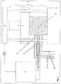
- FIG. 1 the closing unit 1 of the injection molding machine used for injection-compression molding is shown in a simplified representation, wherein the two-part injection-compression molding tool 2 is attached to the clamping plates of the injection molding machine.
- the flow control unit 3 for the injection molding machine and the control unit 4 for regulating the temperature of the steam-heated injection compression tool 2 are shown as block diagrams.
- the control unit is connected to a computer, not shown in detail, for example, computer, on which the required software for performing arithmetic operations and control and control operations is installed.
- the injection compression tool 2 is equipped with four separately controllable heating circuits, of which in the Fig. 1 in each case the flow and return lines 7, 8 for the steam supply (indicated by arrows) of the two front heating circuits can be seen.
- an electrically actuated solenoid valve 5 is incorporated for opening and closing the steam supply.
- Each heating circuit is located in the steam supply line 7 directly at the entrance to the tool 2 via a short metal connection to the tool integrated temperature sensor 6, which is connected to the control unit 4.
- the control unit 4 is coupled to the flow control unit 3 for the injection molding machine via the line S1 to supply a signal from the flow control of the injection molding machine to the control unit 4.
- For the control of the tool temperature only a single signal from the machine sequence control is required, such as "closing the tool time".
- the process sequence for heating the injection-compression molding tool 2 is subdivided into three periods, a first period for heating the injection-compression molding tool to operating temperature (heating period), a second period for further control of the heating of the tool for maintaining the stationary heating state (stationary heating period) and as a third period, the production period, the actual injection molding of the moldings.
- the heating-up period is only required if the tool is used for the first time or is put back into service again after an interruption in production. In the case of short-term faults during operation, re-heating is not required.
- the stationary heating period begins when at the end of a Einschwenkphase the setpoint / Isttemperatur13 for the respective heating circuit results in a deviation less plus / minus 5 ° K.
- control and regulation unit also includes an input unit, a signal input, signal processing and signal output unit, as well as a display unit and memory unit.
- Setpoint temperatures, as so-called pulse time module IZM are recorded as a database on the memory either in graphical and / or tabular form, based on a very specific steam temperature (in this case: 180 ° C.).
- the numerical values available for this purpose form the basis for the arithmetic operations which automatically take place during operation for the purpose of determining the control behavior, whereby the entire practically possible thermal behavior of tool cycles is recorded by the stored modules.
- the Einschwenkmodul comprises one or more Einschwenkphasen, the duration of which are calculated differently, with possibly also several Einschwenkphasen can be introduced in a row.
- the category of the heating character for a heating circuit to be used in the respective application is generally determined by the operator on the basis of empirical values and may optionally automatically skip to another category during the control process if the first input proves to be too inaccurate.
- the heating module includes the work field in terms of the relationship between steam temperature, heating time and set temperature. The mathematical relationship of these basic relationships is based, for example, on an exponential function, the heating character being determined by the magnitude of the exponent.
- the Einschwenkmodul EM (see Tables 2 and 3) includes the working field in terms of the relationship between Einschwenkdauer, Aufmake character and target temperature, based on a specific form of a potential function with reciprocal exponent or on a logarithmic relationship.
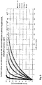
- the pulse time module IZM (see Fig. 3 and Table 4) includes the working field in terms of the relationship between Aufbest character, set temperature and target pulse time, assuming a steady-state operation. Tables 1 to 4 are given at the end of the description.
- the pulse time module is based on a specific form of a potential function, the setpoint temperature and the heating character being variables. The calculation can also be made according to a logarithmic relationship.
- the controlled variable of the method is a temperature whose measuring location is arranged close to the point of entry of the steam into the tool and at the same time also permits thermal information about the peripheral temperature state of the tool via a short, metallic connecting piece with integrated temperature sensor.
- the temperature at this measuring location the closer the temperature state of the tool during heating to the steady state approaching, increasingly adapted to the temperature state, which is measured in the geometric center of a heating circuit in the tool.
- the measuring point temperature is then, depending on the thermal and geometric conditions, always between 2 to 5 ° K above the mean mold temperature and indicates changes in the average mold temperature state, although delayed, but safe.
- the control technology use of this temperature signal is thus consuming, but the advantage of the measuring arrangement that no probes with special effort in the tool per circle placed, maintained and possibly repaired, speaks for the much higher procedural ease of use of this solution.
- the manipulated variable of the method is the duration of the steam volume flow, which is controlled by means of appropriate actuators, e.g. Solenoid valves or engine control valves, time-modulated via the respective flow line is supplied.
- actuators e.g. Solenoid valves or engine control valves
- a condensate drain valve is integrated, via which condensate is removed.
- a target temperature of 165 ° C and for the two heating circuits III and IV of the drive side a target temperature of 155 ° C are given for the two heating circuits I and II of the nozzle side of the tool.
- the heating period begins, wherein the solenoid valves 5 are opened and 100% of the available steam volume flow through the channels of the heating circuits I to IV flow.
- the tool should be closed to avoid unnecessary heat loss.
- the continuous steam supply in the heating-up period is terminated when, according to the heating module (see Fig. 2 and Table 1) an actual temperature would have to be reached, which is a certain amount X (5, 10 or 15 ° C), below the target temperature.
- a certain amount X 5, 10 or 15 ° C
- Each heating character is assigned a certain amount X, as indicated below, the values being stored in the working memory as part of the heating profile: Aufiller character very fast fast normal slowly sluggish Amount X ° K 15 10 10 10 5
- the first Einschwenkphase ⁇ 1 is characterized by a minute modulated decreasing shortening steam pulse mode.
- the duration of the Einschwenkphase depends on the chosen Aufmake character and the height of the desired set temperature. It is automatically generated from the first swivel module stored in the memory of the control unit (see Table 2). Based on the present example results for the two circuits of the nozzle side a Einschwenkdauer ⁇ 1 of 18 minutes and for the circuits of the nozzle side of 20 min.
- the desired pulse duration t soll is important.
- the setpoint pulse duration t soll is identical to the pulse duration which is required for minute-modulated steam pulse operation in order to maintain the stationary operating state at the constant high level in the stationary operating state at a specific setpoint temperature and the specific heating characteristic To maintain temperature level exactly.
- This desired pulse duration t soll is also dependent on the heating character of the respective heating circuit and the height of the desired setpoint temperature. It is also generated from the "pulse time module IZM" stored in the memory of the control unit.
- the following table shows the initial values and the adjustments made or changes in the setpoint pulse duration within the last minute of the first switch-on duration: heating circuits I II III IV Target temperature ° C 165 165 155 155 Desired pulse duration s / min 15.4 15.4 21.1 21.1 Actual temperature at the beginning of the last minute ° C 156 175 129 173 Adjustment of the set pulse duration in the last minute to s / min 30.8 0 42.2 0
- Heating circuit I (at 7 ° C too low actual temperature):
- a postheating time in minutes is automatically determined and triggered, the duration of which is derived in the manner that forms the difference between the heating time at the selected setpoint temperature and the heating time at the measured actual temperature and with a damping factor between 0.5 and 0.9 is multiplied.
- Heating circuit II (actual temperature too high by 7 ° C):
- a heat break is first set, ie the steam supply is interrupted.
- the duration of the required break or break is automatically determined from the heat-up module (category "fast") as follows: Actual temperature: 172 ° C Heating time: 35.9 min set temperature 165 ° C heating up 28.4 min Difference: 7,5 min
- the swelling duration which is characterized progressively per minute with increasing pulses, was determined to be 10 min.
- Heating circuit III (actual temperature 24 ° C too low):
- Heating circuit IV (actual temperature too high by 16 ° C):
- t A lazy is the heating time at setpoint temperature according to the originally selected category "sluggish” t A normal is the heating time at setpoint temperature according to the newly selected category ° C "normal” t A slow (at 155 °): 83.5 min t A normal (155 ° C): 50.1 min
- t soll the time is selected from the pulse time module, which results at setpoint temperature for the newly selected category "normal". t should (at 155 ° C): 15.9 s
- the duration is automatically determined and triggered by the installed calculation software.
- the regulation of the temperature of the individual heating circuits I to IV takes place after completion of the respective heating phase by introducing time-modulated intermittent steam pulses (steam temperature 180 ° C).
- 1 minute was chosen as the time unit, that is to say that a steam pulse exactly predetermined in time is triggered per minute so that the temperature at the measuring location is kept at the desired setpoint temperature level.
- control is always the average value of the temperature, which is measured from the beginning of a heat pulse over 40 to 90%, preferably 75%, of the pulse length to be triggered, used.
- measuring time is used. This ensures that in terms of control technology thermodynamic disturbances in the same control cycle both pulse time extensions and pulse time reductions of up to 25% of the current steam pulse can be made.
- the correction factor K is calculated by means of specific mathematical relationships in dependence on the respectively measured temperature difference ⁇ ⁇ and which, with a positive temperature difference from the differences shape and with a negative temperature difference from the sum of the form of equation (4) resulting corrected pulse length in the current minute in the Effectively made that the pulse time is shortened or extended compared to the desired pulse time.
- the regulation is explained in detail below for the individual heating circuits I to IV.
- the control for the stationary operating period begins immediately after the end of the heating period for the relevant heating circuit, ie when the Einschwenkphase ended and the deviations from the predetermined setpoint temperature is less than plus / minus 5 ° K are.
- the measured actual temperature at the end of the swivel phase is 163.5 ° C.
- a temperature of 163.5 ° C. is measured at the beginning of the pulse (time t 0 ) and a temperature of 165.3 ° C. at the time t (75) .
- a temperature of 166.5 ° C. is measured at the start of the pulse (time t o ) and a temperature of 168.5 ° C. at the time t (75) .
- the third steam pulse is now re- triggered with the newly calculated value t soll , over a period of 14.98 s.
- the temperature measurement immediately after completion of this steam pulse duration was below the target temperature by 0.4 ° K, so that no further correction of the steam pulse duration is required.
- the method for "sliding" adaptation of the desired pulse length also has the objective of
- the minute-modulated intermittent control phase for the stationary operating period is initiated after completion of the second Einschwenkphase.
- the setpoint pulse time t setpoint is 26.4 s / min (heating character "sluggish").
- a temperature of 153 ° C. was measured at time t o and 154.6 ° C. at time t 75 . This results in a mean value of 153.8 ° C and thus a ⁇ ⁇ of -1.2 ° K.
- the temperature difference setpoint-actual set to a ⁇ ⁇ of +0.6 ° K in the second minute.
- the control system indicates to the operator via the signal "ready for operation" that the production process of the molded parts can be started.
- thermosetting molding compound is injected at a temperature of 80 ° C in the two mold cavities of the slightly open tool (each 1350 g). Thereafter, the tool is closed, wherein the dipping edge closes the cavity before the end of the closing stroke, so that only volatile fission products can escape and no material can escape.
- the curing or curing process begins, wherein optimal conditions are achieved when the predetermined set temperatures 165 ° C and 155 ° C for the heating circuits I to IV are maintained during the injection cycles during the entire operating period.
- the control of the mold temperature is always carried out according to the same control mechanism as in the stationary heating period
- a time-adjustable delay time from the signal S 1 "close tool" for triggering the steam pulse is provided as selectable in the control unit ,
- the value 0 has been selected as the delay time, that is, the delay time.
- the first steam pulse is triggered synchronously with the signal S1, "close tool", for all heating circuits I to IV.
- Variant A control with fixed time module (in the example, one minute was selected as the time module)
- the measuring time t o to t 75 begins with the initiation of the steam pulse which occurs before the tool closes (before S1) and ends after a period of 75% of the setpoint pulse duration.
- the mean value of the temperatures measured over this period t o to t 75 is used as intended for the calculation of the corrected setpoint pulse duration according to equation (4). Any necessary correction of t want but made to the pulse length, which starts from S1. t to in the preceding equation is always calculated in the preceding control cycle corrected to t -time.
- the new extended pause time is calculated from the remainder of the old aborted extended pause plus new set pause, which is derived from the impulse length of the current impulse.
- Variant B With cycle-time-modulated control
- the cycle time for minute-modulated process conditions is first determined by measuring the time between the signals S 1 of adjacent injection cycles, taking into account one or more injection cycles.
- the fixed specification of the cycle time by the machine operator is possible.
- the cycle-time-modulated setpoint pulse t z soll is also triggered at the beginning of the signal S 1.
- This mode has the advantage that the entire amount of heat required in the cycle to maintain the desired temperature level of the tool is introduced at the beginning of the cycle. This results in the advantages for the possible shortening of the cycle time (hardening time) and the flow-technically more favorable conditions during the molding process compared to conventional heating methods.
- the tool temperature control takes place in cycle time modulated driving mode analogous to the minute modulated.
- cycle-time-modulated control there is the danger of possible fluctuations of the cycle time, caused for example by by different lengths of machine movement times, spontaneously performed operator actions u. a.
- thermodynamic disturbances are detected and corrected in the same cycle.
- Particularly advantageous is the exact metered introduction of all or most of the heat required per cycle at the beginning of the cycle.
- the molding process can take place at higher tool contour temperatures. The result is a better, more faithful flow out of the molding compound in the shaping and the resulting reduction of technologically caused rejects.
- the higher energy input into the tool at the beginning of the cycle results in a possible reduction of the cycle time by 5 to 15%.
- the heating and control of the mold temperature for the production of the light carrier according to the example shown made possible a stable quality-compliant production while maintaining a cycle time of 65 s.
- a shortening of the cycle time leads as a side effect to heating cost savings for the provision of steam.
- productivity can be increased by up to 15% and scrap rates reduced by up to 30%.
Landscapes
- Engineering & Computer Science (AREA)
- Physics & Mathematics (AREA)
- Manufacturing & Machinery (AREA)
- Mechanical Engineering (AREA)
- Health & Medical Sciences (AREA)
- Oral & Maxillofacial Surgery (AREA)
- Thermal Sciences (AREA)
- General Physics & Mathematics (AREA)
- Automation & Control Theory (AREA)
- Injection Moulding Of Plastics Or The Like (AREA)
- Processing And Handling Of Plastics And Other Materials For Molding In General (AREA)
- Heating, Cooling, Or Curing Plastics Or The Like In General (AREA)
Claims (15)
- Procédé de mise à température et de régulation d'une température d'un outil chauffé par un fluide caloporteur liquide et/ou sous forme de vapeur avec au moins un circuit de chauffage pour la mise en forme et/ou la fixation de pièces moulées en matériaux polymères thermodurcissables ou réticulables, et des moyens pour la réalisation d'une comparaison entre valeur réelle et valeur de consigne d'une température réelle mesurée en tant que valeur réglable avec une température consigne définie, une unité de contrôle et de régulation, un profil de chauffage, un module de mise à température, un module de pivotement et un module de durée d'impulsion, caractérisé en ce que avant le début d'un processus de mise à température et de régulation, un profil de chauffage propre à un circuit de chauffage est déposé dans la mémoire de l'unité de contrôle et de régulation pour servir de base pour la régulation de la température de l'outil, ledit profil étant formé au moins par le module de mise à température avec des durées de mise à température dépendantes de la température consigne définie et des caractéristiques de mise à température propres au circuit de chauffage, par un premier et un second module de pivotement avec des valeurs concernant la durée de pivotement dépendantes de la température consigne et des caractéristiques de mise à température, où le module de pivotement contient le champ de travail en termes de relation entre la durée de pivotement, la caractéristique de mise à température et la température consigne, basée sur une forme spécifique d'une fonction potentielle à exposant réciproque ou sur une relation logarithmique, et par le module de durée d'impulsion avec des durées d'impulsion consignes pour l'apport de fluide caloporteur en fonction de la température consigne et des caractéristiques de mise à température, où les modules individuels sont associés à une température spécifique du fluide caloporteur et une caractéristique de mise à température propre au circuit de chauffage est sélectionnée avant le début de la mise à température.
- Procédé selon la revendication 1, caractérisé en ce que le processus de mise à température et de régulation est divisé en au moins deux périodes, une période de mise à température avec au moins une phase de mise à température et au moins une phase de pivotement et une période de chauffage stationnaire avec un comportement de régulation différent, où la période de chauffage stationnaire est destinée à la régulation continue du chauffage de l'outil afin de maintenir un état de chauffage stationnaire, pendant les périodes, le fluide caloporteur est amené au circuit de chauffage, lors de la phase de pivotement l'apport de fluide caloporteur est interrompu pour une durée réglable, la température réelle au niveau de l'outil est mesurée une première fois au cours de la période de pivotement, directement au niveau de l'entrée du fluide caloporteur dans l'outil et l'apport de fluide caloporteur au cours de la période de chauffage stationnaire est interrompue pour une durée réglable en fonction de la comparaison entre la température consigne et la température réelle, de telle manière que des impulsions de fluide caloporteur de longueur ou durée différente sont générées, si nécessaire avec des interruptions complètes, pour une durée réglable, de l'apport en fluide caloporteur, en tant que temps de pause, et les modifications dépendantes de la température sont mises en oeuvre par un apport de fluide caloporteur via une vanne pouvant être commutée entre une position « ouverte » et une position « fermée » , où l'actionnement pour une durée réglable de la vanne est mise en oeuvre au moyen un algorithme de régulation prédéfini.
- Procédé selon la revendication 2, caractérisé en ce que lors de la période de mise à température, la phase de mise à température caractérisée par un apport continu de fluide caloporteur est arrêtée dans l'hypothèse où une température réelle associée à une caractéristique de mise à température prédéfinie à partir du profil de chauffage se situe sous la température consigne d'un certain montant de 2 à 10% de la température consigne.
- Procédé selon l'une des revendications 1 à 3, caractérisé en ce que lors de la première phase de pivotement, des impulsions de fluide caloporteur se raccourcissant de manière dégressive modulée dans le temps sont introduites, afin de rapprocher de manière dosée la température réelle de la température consigne, la première comparaison entre la température réelle et la température consigne est réalisée au début du dernier module de temps de cette phase de pivotement, où en cas de déviations de la température réelle de la température consigne supérieures à une valeur limite basse inférieure à la température consigne ou supérieures à une valeur limite haute supérieure à la température consigne, une prolongation ou un raccourcissement, si nécessaire jusqu'à la valeur 0, de la durée d'impulsion de fluide caloporteur du dernière module de temps de la première phase de pivotement est réalisée, et à la fin de la première phase de pivotement, une seconde comparaison entre la température consigne et la température réelle est réalisée, où en cas de déviations à l'intérieur d'une plage de tolérance, une transition vers une période de chauffage stationnaire se produit, et en cas de déviations en dehors de la plage de tolérance, d'autres corrections par régulation sont initiées.
- Procédé selon la revendication 4, caractérisé en ce que la durée des impulsions de fluide caloporteur pour la première phase de pivotement dégressive modulée dans le temps τ est déterminée selon la formule de calcul suivante :
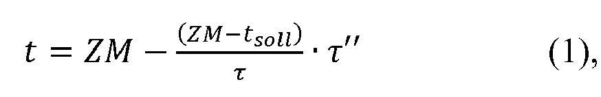 t est la durée d'impulsion à l'instant réel respectif, tsoll est la durée d'impulsion consigne selon le module de durée d'impulsion, τ" est le temps de référence actuel après le début de la phase de pivotement, τ est la durée de la phase de pivotement en min (durée de pivotement commence à 1) et ZM est le module de temps en secondes ;et la durée de pivotement est déduite du premier module de pivotement.
 - Procédé selon l'une des revendications 4 ou 5, caractérisé en ce que les corrections sont effectuées de la manière suivante :a) si la température réelle est trop basse de 5 à 15°K, une durée de réchauffement est d'abord initiée, dont la durée d'introduction de fluide caloporteur est déduite du module de mise à température de telle manière que la différence entre la durée de mise à température à la température consigne et la durée de mise à température à la température réelle est déterminée et multipliée par un facteur d'atténuation entre 0,5 et 0,9 et une seconde phase de pivotement dégressive modulée dans le temps est initiée juste après, dont la durée de l'impulsion de vapeur est calculée selon l'équation (1) en prenant en compte la durée de pivotement déduite du second module de pivotement,
oub) si la température réelle est trop basse de plus de 15°K, un passage vers une caractéristique de chauffage avec une durée de chauffage plus longue est automatiquement effectué par réglage et une période de réchauffement est initiée dont la durée est déterminée en fonction de l'ampleur de la déviation selon la formule suivante :
ouc) si la température réelle est trop élevée de 5 à 15°K, une pause est d'abord initiée dont la durée est déterminée comme étant la différence entre les durées associées à la température réelle et à la température consigne dans le module de mise à température, multipliée par un facteur d'atténuation prédéfini compris entre 0,5 et 0,9, et une phase de pivotement progressive modulée dans le temps avec une durée de pivotement prédéfinie est initiée, où la durée d'impulsion des impulsions de vapeur à introduire par module de temps est déterminée selon la formule de calcul suivante : t est la durée d'impulsion en s/min à l'instant d'impulsion respectif,tsoll est la longueur d'impulsion consigne en s/min selon la température consigne conforme au module de mise à température, τ est la durée de pivotement et τ* est la durée de référence actuelle (débute après la fin du temps de pause) ;oud) si la température réelle est trop élevée de plus de 15°K, un passage vers une caractéristique de mise à température avec une durée de mise à température plus courte, où une « pause de chauffage » est d'abord initiée afin de réduire la température réelle, la durée de ladite pause est déterminée comme étant la différence entre la durée de mise à température à la température consigne selon la caractéristique de mise à température initialement sélectionnée et la durée de mise à température à la température consigne selon la caractéristique de mise à température ayant une durée de mise à température plus courte, multipliée par une facteur d'atténuation compris entre 0,5 et 0,9, et une phase de pivotement progressive modulée dans le temps avec des impulsions de fluide caloporteur est initiée de manière similaire à c).
 - Procédé selon la revendication 6, caractérisé en ce que lors de l'initiation d'une phase de pivotement progressive, une durée qui correspond à 5 à 15, de préférence 10 fois le module de temps sélectionné, est définie, où la durée définie agit comme une corrélation entre le facteur d'atténuation et la durée de pivotement de telle manière que lorsqu'un facteur d'atténuation plus élevé est choisi, la durée de pivotement doit être plus petite est inversement.
- Procédé selon l'une des revendications 2 à 7, caractérisé en ce que au cours de la période de chauffage stationnaire, la valeur moyenne de la température, laquelle est déterminée depuis le début de l'impulsion de fluide caloporteur respective sur une période de mesure de 40 à 90%, de préférence 75% de la longueur d'impulsion à déclencher et qu'à la fin de la période de mesure, une correction de la durée d'impulsion appelée durée d'impulsion corrigée est déterminée en fonction de la différence de température mesurée entre la valeur moyenne de la température réelle et la température consigne, ladite durée d'impulsion corrigée servant à raccourcir ou prolonger la durée de l'impulsion de fluide caloporteur actuelle après la durée de mesure.
- Procédé selon la revendication 8, caractérisé en ce que la durée d'impulsion corrigée pour raccourcir ou prolonger l'impulsion de fluide caloporteur actuelle est déterminée comme suit :
 tKorr est la durée d'impulsion corrigée, tsoll est la durée d'impulsion à la température consigne (la valeur de la température consigne est déduite du module de durée d'impulsion) et K est un facteur de correction dépendant de la température,et en cas de différence de température positive, la soustraction de l'équation (4) est appliquée et en cas de différence de température négative, l'addition de l'équation (4) est appliquée.
 - Procédé selon l'une des revendications 2 à 9, caractérisé en ce que pendant la régulation dans la phase de chauffage stationnaire, après l'introduction de la première impulsion de fluide caloporteur, un ajustement « glissant » de la longueur de l'impulsion consigne est effectué pour toutes les impulsions suivantes lorsque les déviations entre la température réelle et la température consigne sont d'au moins 0,5 °K et le signe de la déviation de température actuellement déterminée correspond aux déviations déterminées lors d'un nombre défini d'impulsions de vapeur immédiatement précédentes, où une nouvelle durée d'impulsion consigne tsollneu est calculée comme suit :

tsoll est la dernière longueur d'impulsion consigne actualisée, K est la valeur du facteur de correction dépendant de la température actuellement déterminée et α est un facteur d'atténuation dont le montant est compris entre 0,3 et 1, de préférence égal à 0,5. - Procédé selon l'une des revendications 2 à 10, caractérisé en ce que une période de production pour la mise en forme et/ou la fixation de parties moulées est initiée quand une valeur de tolérance prédéfinie d'une déviation de régulation est dépassée à la baisse au moins une fois lors de la comparaison entre température consigne et température réelle dans la phase de chauffage stationnaire, l'apport du fluide caloporteur au cours de la période de production est synchronisé avec le moment de déclenchement d'un signal de la commande de déroulement de la machine de production et dans la période de production suivante, la régulation selon la période de chauffage stationnaire est maintenue, où l'introduction d'une impulsion de fluide caloporteur est déclenchée par le signal de la commande de déroulement de la machine de production et l'introduction et la mesure temporelle d'impulsions de fluide caloporteur est réglée sur le moment du déclenchement, synchrone avec le cycle, du signal et la durée du cycle de production.
- Procédé selon la revendication 11, caractérisé en ce que lors de la régulation modulée au cours de la période de production, deux cas distincts se présentent, où dans le premier cas, lorsque du fluide caloporteur est déjà amené au moment du déclenchement du signal sélectionné de la commande de déroulement de la machine de production, à partir de ce moment, du fluide caloporteur est par la suite introduit selon la durée d'impulsion consigne calculée et une période de pause prolongée est déterminée selon l'équation suivante et déclenchée :
 tv,P est la pause prolongée, ti,v est la durée d'impulsion déclenchée avant le signal et ZM est le module de temps sélectionné en secondes,et dans le deuxième cas, lorsque la vanne de réglage pour l'alimentation en vapeur est fermée au moment du déclenchement du signal sélectionné de la commande de déroulement de la machine de production, la vanne est ouverte et du fluide caloporteur est introduit selon la durée d'impulsion consigne et une interruption de l'alimentation en fluide caloporteur sous forme d'un temps de pause tv,p prolongé est déterminée selon l'équation suivante et déclenchée :
- Procédé selon l'une des revendications 11 ou 12, caractérisé en ce que lors d'une régulation modulée dans le temps dans la période de production, le temps entre deux signaux identiques de cycles avoisinants est déterminé ou ce temps est déjà prédéfini, la durée d'impulsion consigne est déterminée selon l'équation suivante :
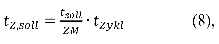 tZ,soll est la longueur d'impulsion/la durée du cycle, tsoll est la longueur d'impulsion de la dernière impulsion modulée dans le temps, ZM est le module de temps sélectionné en secondes et tZykl est la durée du cycle en secondes ;et l'impulsion consigne tZ,soll est déclenchée au début du signal.
 - Procédé selon la revendication 6, caractérisé en ce que en cas de dépassements à la hausse du temps de cycle actuel mesuré par une valeur consigne prédéfinie, un ajustement de la durée d'impulsion de fluide caloporteur est effectuée lors du cycle suivant, selon l'équation suivante :

- Procédé selon l'une des revendications 12 à 14, caractérisé en ce que lors d'une interruption d'une durée de cycle définie, une commutation automatique vers une régulation modulée dans le temps est réalisée pour une période prédéterminée.
Applications Claiming Priority (1)
| Application Number | Priority Date | Filing Date | Title |
|---|---|---|---|
| DE201210100327 DE102012100327A1 (de) | 2012-01-16 | 2012-01-16 | Verfahren zur Aufheizung und Regelung der Temperatur eines mit einem flüssigen oder dampfförmigen Wärmeträger beheizten Werkzeuges |
Publications (2)
| Publication Number | Publication Date |
|---|---|
| EP2615518A1 EP2615518A1 (fr) | 2013-07-17 |
| EP2615518B1 true EP2615518B1 (fr) | 2017-03-29 |
Family
ID=47559287
Family Applications (1)
| Application Number | Title | Priority Date | Filing Date |
|---|---|---|---|
| EP13151134.7A Not-in-force EP2615518B1 (fr) | 2012-01-16 | 2013-01-14 | Procédé de mise en temperature et de régulation de la température d'un outil de fabrication chauffé par un fluide en phase liquide et/ou vapeur |
Country Status (4)
| Country | Link |
|---|---|
| EP (1) | EP2615518B1 (fr) |
| DE (1) | DE102012100327A1 (fr) |
| ES (1) | ES2628342T3 (fr) |
| PL (1) | PL2615518T3 (fr) |
Families Citing this family (1)
| Publication number | Priority date | Publication date | Assignee | Title |
|---|---|---|---|---|
| CN107584738A (zh) * | 2017-09-13 | 2018-01-16 | 安徽安缆模具有限公司 | 一种注塑模具智能化温度控制系统 |
Family Cites Families (4)
| Publication number | Priority date | Publication date | Assignee | Title |
|---|---|---|---|---|
| CH484711A (de) * | 1967-09-15 | 1970-01-31 | Buehler Ag Geb | Verfahren und Vorrichtung zur Temperaturregelung bei Druck- und Spritzgiessmaschinen |
| DE4141996A1 (de) | 1991-12-19 | 1993-06-24 | Bosch Gmbh Robert | Verfahren zur ueberwachung und/oder regelung eines formgebungsprozesses fuer vernetzende formmaterialien |
| DE4307347C2 (de) * | 1993-03-09 | 1996-09-26 | Werner Kotzab | Verfahren zum Temperieren einer Spritzgießform |
| CZ289862B6 (cs) * | 1994-09-27 | 2002-04-17 | Erich Dr. Liehr | Způsob temperování jednotek vstřikovacích licích strojů, zejména pro zpracování zesítitelných polymerů, a jednotek tvarovacích nástrojů pro zpracování plastů |
-
2012
- 2012-01-16 DE DE201210100327 patent/DE102012100327A1/de not_active Withdrawn
-
2013
- 2013-01-14 PL PL13151134T patent/PL2615518T3/pl unknown
- 2013-01-14 EP EP13151134.7A patent/EP2615518B1/fr not_active Not-in-force
- 2013-01-14 ES ES13151134.7T patent/ES2628342T3/es active Active
Also Published As
| Publication number | Publication date |
|---|---|
| EP2615518A1 (fr) | 2013-07-17 |
| DE102012100327A1 (de) | 2013-07-18 |
| PL2615518T3 (pl) | 2017-09-29 |
| ES2628342T3 (es) | 2017-08-02 |
Similar Documents
| Publication | Publication Date | Title |
|---|---|---|
| EP3661720B1 (fr) | Procédé de thermorégulation variothermique d'outils de moulage par injection | |
| EP2583811B1 (fr) | Procédé de quantification de basculements de procédés dans le cadre d'un processus d'injection d'une machine de moulage par injection | |
| EP0704293B1 (fr) | Procédé de régulation en température d'unités d'injection et de moules d'injection de matières plastiques | |
| DE4309880C2 (de) | Verfahren und Anlage zur Temperierung von Formwerkzeugen für die Kunststoffverarbeitung | |
| EP1372934A1 (fr) | Procede d'equilibrage automatique du remplissage volumetrique de cavites | |
| DE102015114845B4 (de) | Verfahren und Gerät zum Spritzgießen von Kunststoffmaterialien | |
| WO2002076704A1 (fr) | Procede pour la regulation du retrait de pieces moulees par injection | |
| DE102009046835A1 (de) | Spritzgießwerkzeug | |
| DE102009027646A1 (de) | Vorrichtung und Verfahren zur Herstellung dickwandiger Kunststoffformteile mit verringerten Einfallstellen durch Spritzgießen oder -prägen | |
| AT514847B1 (de) | Verfahren zur Bestimmung eines Sollwerts für einen Einstellparameter | |
| EP2615518B1 (fr) | Procédé de mise en temperature et de régulation de la température d'un outil de fabrication chauffé par un fluide en phase liquide et/ou vapeur | |
| DE102010022508B4 (de) | Verfahren zum Herstellen eines Faserverbundbauteils | |
| WO2004058476A2 (fr) | Procede pour reguler la production de pieces moulees par injection | |
| DE4436117C2 (de) | Verfahren zur Temperierung von Spritzgießmaschineneinheiten und Formwerkzeugeinheiten für die Kunststoffverarbeitung | |
| DE2543088A1 (de) | Regelverfahren fuer eine spritzgussvorrichtung | |
| DE29917075U1 (de) | Vorrichtung zum Temperieren von Formwerkzeugen von Spritzgußmaschinen | |
| EP0315999B1 (fr) | Procédé de remplissage de moule reproductible avec des matières à mouler | |
| EP2298530B1 (fr) | Dispositif et procédé destinés à tempérer un outil de moulage par injection | |
| DE102012103304B4 (de) | Verfahren und Vorrichtung zur temperaturabhängigen Steuerung des Spritzgießprozesses bei der Herstellung von Kunststoffbauteilen | |
| DE102014108730A1 (de) | Verfahren zum Betreiben einer Spritzgießmaschine | |
| DE4436126C2 (de) | Verfahren zur Temperierung von Spritzgießmaschineneinheiten und Formwerkzeugeinheiten für die Kunststoffverarbeitung | |
| WO2019025074A1 (fr) | Procédé et dispositif pour fabriquer un élément d'habillage d'un véhicule à moteur, utilisation du dispositif | |
| DE102007029977A1 (de) | Verfahren zur Durchführung des Schließkraftabbaus bei einer Schließeinheit einer Spritzgießmaschine | |
| AT8285U1 (de) | Verfahren zum spritzprägen von kunststoff | |
| DE10316158A1 (de) | Verfahren zur Herstellung einer Slushhaut |
Legal Events
| Date | Code | Title | Description |
|---|---|---|---|
| PUAI | Public reference made under article 153(3) epc to a published international application that has entered the european phase |
Free format text: ORIGINAL CODE: 0009012 |
|
| AK | Designated contracting states |
Kind code of ref document: A1 Designated state(s): AL AT BE BG CH CY CZ DE DK EE ES FI FR GB GR HR HU IE IS IT LI LT LU LV MC MK MT NL NO PL PT RO RS SE SI SK SM TR |
|
| AX | Request for extension of the european patent |
Extension state: BA ME |
|
| 17P | Request for examination filed |
Effective date: 20130911 |
|
| RBV | Designated contracting states (corrected) |
Designated state(s): AL AT BE BG CH CY CZ DE DK EE ES FI FR GB GR HR HU IE IS IT LI LT LU LV MC MK MT NL NO PL PT RO RS SE SI SK SM TR |
|
| 19U | Interruption of proceedings before grant |
Effective date: 20151016 |
|
| 19W | Proceedings resumed before grant after interruption of proceedings |
Effective date: 20160201 |
|
| 17Q | First examination report despatched |
Effective date: 20160502 |
|
| GRAP | Despatch of communication of intention to grant a patent |
Free format text: ORIGINAL CODE: EPIDOSNIGR1 |
|
| STAA | Information on the status of an ep patent application or granted ep patent |
Free format text: STATUS: GRANT OF PATENT IS INTENDED |
|
| RIC1 | Information provided on ipc code assigned before grant |
Ipc: B29C 35/02 20060101ALI20161108BHEP Ipc: B29C 45/78 20060101ALI20161108BHEP Ipc: G05D 23/19 20060101AFI20161108BHEP Ipc: B29K 101/10 20060101ALI20161108BHEP Ipc: B29C 35/04 20060101ALI20161108BHEP |
|
| INTG | Intention to grant announced |
Effective date: 20161206 |
|
| GRAS | Grant fee paid |
Free format text: ORIGINAL CODE: EPIDOSNIGR3 |
|
| GRAA | (expected) grant |
Free format text: ORIGINAL CODE: 0009210 |
|
| STAA | Information on the status of an ep patent application or granted ep patent |
Free format text: STATUS: THE PATENT HAS BEEN GRANTED |
|
| AK | Designated contracting states |
Kind code of ref document: B1 Designated state(s): AL AT BE BG CH CY CZ DE DK EE ES FI FR GB GR HR HU IE IS IT LI LT LU LV MC MK MT NL NO PL PT RO RS SE SI SK SM TR |
|
| REG | Reference to a national code |
Ref country code: GB Ref legal event code: FG4D Free format text: NOT ENGLISH |
|
| REG | Reference to a national code |
Ref country code: CH Ref legal event code: EP |
|
| REG | Reference to a national code |
Ref country code: AT Ref legal event code: REF Ref document number: 880315 Country of ref document: AT Kind code of ref document: T Effective date: 20170415 |
|
| REG | Reference to a national code |
Ref country code: IE Ref legal event code: FG4D Free format text: LANGUAGE OF EP DOCUMENT: GERMAN |
|
| REG | Reference to a national code |
Ref country code: DE Ref legal event code: R096 Ref document number: 502013006764 Country of ref document: DE |
|
| PG25 | Lapsed in a contracting state [announced via postgrant information from national office to epo] |
Ref country code: NO Free format text: LAPSE BECAUSE OF FAILURE TO SUBMIT A TRANSLATION OF THE DESCRIPTION OR TO PAY THE FEE WITHIN THE PRESCRIBED TIME-LIMIT Effective date: 20170629 Ref country code: HR Free format text: LAPSE BECAUSE OF FAILURE TO SUBMIT A TRANSLATION OF THE DESCRIPTION OR TO PAY THE FEE WITHIN THE PRESCRIBED TIME-LIMIT Effective date: 20170329 Ref country code: GR Free format text: LAPSE BECAUSE OF FAILURE TO SUBMIT A TRANSLATION OF THE DESCRIPTION OR TO PAY THE FEE WITHIN THE PRESCRIBED TIME-LIMIT Effective date: 20170630 Ref country code: FI Free format text: LAPSE BECAUSE OF FAILURE TO SUBMIT A TRANSLATION OF THE DESCRIPTION OR TO PAY THE FEE WITHIN THE PRESCRIBED TIME-LIMIT Effective date: 20170329 Ref country code: LT Free format text: LAPSE BECAUSE OF FAILURE TO SUBMIT A TRANSLATION OF THE DESCRIPTION OR TO PAY THE FEE WITHIN THE PRESCRIBED TIME-LIMIT Effective date: 20170329 |
|
| REG | Reference to a national code |
Ref country code: ES Ref legal event code: FG2A Ref document number: 2628342 Country of ref document: ES Kind code of ref document: T3 Effective date: 20170802 Ref country code: NL Ref legal event code: MP Effective date: 20170329 |
|
| PG25 | Lapsed in a contracting state [announced via postgrant information from national office to epo] |
Ref country code: RS Free format text: LAPSE BECAUSE OF FAILURE TO SUBMIT A TRANSLATION OF THE DESCRIPTION OR TO PAY THE FEE WITHIN THE PRESCRIBED TIME-LIMIT Effective date: 20170329 Ref country code: SE Free format text: LAPSE BECAUSE OF FAILURE TO SUBMIT A TRANSLATION OF THE DESCRIPTION OR TO PAY THE FEE WITHIN THE PRESCRIBED TIME-LIMIT Effective date: 20170329 Ref country code: LV Free format text: LAPSE BECAUSE OF FAILURE TO SUBMIT A TRANSLATION OF THE DESCRIPTION OR TO PAY THE FEE WITHIN THE PRESCRIBED TIME-LIMIT Effective date: 20170329 Ref country code: BG Free format text: LAPSE BECAUSE OF FAILURE TO SUBMIT A TRANSLATION OF THE DESCRIPTION OR TO PAY THE FEE WITHIN THE PRESCRIBED TIME-LIMIT Effective date: 20170629 |
|
| REG | Reference to a national code |
Ref country code: DE Ref legal event code: R082 Ref document number: 502013006764 Country of ref document: DE Representative=s name: WEIDNER STERN JESCHKE PATENTANWAELTE PARTNERSC, DE |
|
| PG25 | Lapsed in a contracting state [announced via postgrant information from national office to epo] |
Ref country code: NL Free format text: LAPSE BECAUSE OF FAILURE TO SUBMIT A TRANSLATION OF THE DESCRIPTION OR TO PAY THE FEE WITHIN THE PRESCRIBED TIME-LIMIT Effective date: 20170329 |
|
| PG25 | Lapsed in a contracting state [announced via postgrant information from national office to epo] |
Ref country code: EE Free format text: LAPSE BECAUSE OF FAILURE TO SUBMIT A TRANSLATION OF THE DESCRIPTION OR TO PAY THE FEE WITHIN THE PRESCRIBED TIME-LIMIT Effective date: 20170329 Ref country code: SK Free format text: LAPSE BECAUSE OF FAILURE TO SUBMIT A TRANSLATION OF THE DESCRIPTION OR TO PAY THE FEE WITHIN THE PRESCRIBED TIME-LIMIT Effective date: 20170329 Ref country code: RO Free format text: LAPSE BECAUSE OF FAILURE TO SUBMIT A TRANSLATION OF THE DESCRIPTION OR TO PAY THE FEE WITHIN THE PRESCRIBED TIME-LIMIT Effective date: 20170329 |
|
| PG25 | Lapsed in a contracting state [announced via postgrant information from national office to epo] |
Ref country code: IS Free format text: LAPSE BECAUSE OF FAILURE TO SUBMIT A TRANSLATION OF THE DESCRIPTION OR TO PAY THE FEE WITHIN THE PRESCRIBED TIME-LIMIT Effective date: 20170729 Ref country code: SM Free format text: LAPSE BECAUSE OF FAILURE TO SUBMIT A TRANSLATION OF THE DESCRIPTION OR TO PAY THE FEE WITHIN THE PRESCRIBED TIME-LIMIT Effective date: 20170329 Ref country code: PT Free format text: LAPSE BECAUSE OF FAILURE TO SUBMIT A TRANSLATION OF THE DESCRIPTION OR TO PAY THE FEE WITHIN THE PRESCRIBED TIME-LIMIT Effective date: 20170731 |
|
| REG | Reference to a national code |
Ref country code: DE Ref legal event code: R097 Ref document number: 502013006764 Country of ref document: DE |
|
| PG25 | Lapsed in a contracting state [announced via postgrant information from national office to epo] |
Ref country code: DK Free format text: LAPSE BECAUSE OF FAILURE TO SUBMIT A TRANSLATION OF THE DESCRIPTION OR TO PAY THE FEE WITHIN THE PRESCRIBED TIME-LIMIT Effective date: 20170329 |
|
| PLBE | No opposition filed within time limit |
Free format text: ORIGINAL CODE: 0009261 |
|
| STAA | Information on the status of an ep patent application or granted ep patent |
Free format text: STATUS: NO OPPOSITION FILED WITHIN TIME LIMIT |
|
| 26N | No opposition filed |
Effective date: 20180103 |
|
| PG25 | Lapsed in a contracting state [announced via postgrant information from national office to epo] |
Ref country code: SI Free format text: LAPSE BECAUSE OF FAILURE TO SUBMIT A TRANSLATION OF THE DESCRIPTION OR TO PAY THE FEE WITHIN THE PRESCRIBED TIME-LIMIT Effective date: 20170329 |
|
| REG | Reference to a national code |
Ref country code: CH Ref legal event code: PL |
|
| PG25 | Lapsed in a contracting state [announced via postgrant information from national office to epo] |
Ref country code: MT Free format text: LAPSE BECAUSE OF FAILURE TO SUBMIT A TRANSLATION OF THE DESCRIPTION OR TO PAY THE FEE WITHIN THE PRESCRIBED TIME-LIMIT Effective date: 20170329 |
|
| PG25 | Lapsed in a contracting state [announced via postgrant information from national office to epo] |
Ref country code: LU Free format text: LAPSE BECAUSE OF NON-PAYMENT OF DUE FEES Effective date: 20180114 Ref country code: FR Free format text: LAPSE BECAUSE OF NON-PAYMENT OF DUE FEES Effective date: 20180131 |
|
| REG | Reference to a national code |
Ref country code: IE Ref legal event code: MM4A |
|
| REG | Reference to a national code |
Ref country code: FR Ref legal event code: ST Effective date: 20180928 |
|
| REG | Reference to a national code |
Ref country code: BE Ref legal event code: MM Effective date: 20180131 |
|
| PG25 | Lapsed in a contracting state [announced via postgrant information from national office to epo] |
Ref country code: CH Free format text: LAPSE BECAUSE OF NON-PAYMENT OF DUE FEES Effective date: 20180131 Ref country code: BE Free format text: LAPSE BECAUSE OF NON-PAYMENT OF DUE FEES Effective date: 20180131 Ref country code: LI Free format text: LAPSE BECAUSE OF NON-PAYMENT OF DUE FEES Effective date: 20180131 |
|
| PG25 | Lapsed in a contracting state [announced via postgrant information from national office to epo] |
Ref country code: IE Free format text: LAPSE BECAUSE OF NON-PAYMENT OF DUE FEES Effective date: 20180114 |
|
| REG | Reference to a national code |
Ref country code: AT Ref legal event code: MM01 Ref document number: 880315 Country of ref document: AT Kind code of ref document: T Effective date: 20180114 |
|
| PG25 | Lapsed in a contracting state [announced via postgrant information from national office to epo] |
Ref country code: AT Free format text: LAPSE BECAUSE OF NON-PAYMENT OF DUE FEES Effective date: 20180114 |
|
| PG25 | Lapsed in a contracting state [announced via postgrant information from national office to epo] |
Ref country code: MC Free format text: LAPSE BECAUSE OF FAILURE TO SUBMIT A TRANSLATION OF THE DESCRIPTION OR TO PAY THE FEE WITHIN THE PRESCRIBED TIME-LIMIT Effective date: 20170329 |
|
| PG25 | Lapsed in a contracting state [announced via postgrant information from national office to epo] |
Ref country code: TR Free format text: LAPSE BECAUSE OF FAILURE TO SUBMIT A TRANSLATION OF THE DESCRIPTION OR TO PAY THE FEE WITHIN THE PRESCRIBED TIME-LIMIT Effective date: 20170329 |
|
| PG25 | Lapsed in a contracting state [announced via postgrant information from national office to epo] |
Ref country code: HU Free format text: LAPSE BECAUSE OF FAILURE TO SUBMIT A TRANSLATION OF THE DESCRIPTION OR TO PAY THE FEE WITHIN THE PRESCRIBED TIME-LIMIT; INVALID AB INITIO Effective date: 20130114 |
|
| PG25 | Lapsed in a contracting state [announced via postgrant information from national office to epo] |
Ref country code: CY Free format text: LAPSE BECAUSE OF FAILURE TO SUBMIT A TRANSLATION OF THE DESCRIPTION OR TO PAY THE FEE WITHIN THE PRESCRIBED TIME-LIMIT Effective date: 20170329 Ref country code: MK Free format text: LAPSE BECAUSE OF NON-PAYMENT OF DUE FEES Effective date: 20170329 |
|
| PG25 | Lapsed in a contracting state [announced via postgrant information from national office to epo] |
Ref country code: AL Free format text: LAPSE BECAUSE OF FAILURE TO SUBMIT A TRANSLATION OF THE DESCRIPTION OR TO PAY THE FEE WITHIN THE PRESCRIBED TIME-LIMIT Effective date: 20170329 |
|
| PGFP | Annual fee paid to national office [announced via postgrant information from national office to epo] |
Ref country code: CZ Payment date: 20201229 Year of fee payment: 9 |
|
| PGFP | Annual fee paid to national office [announced via postgrant information from national office to epo] |
Ref country code: IT Payment date: 20210129 Year of fee payment: 9 |
|
| PGFP | Annual fee paid to national office [announced via postgrant information from national office to epo] |
Ref country code: PL Payment date: 20210104 Year of fee payment: 9 Ref country code: GB Payment date: 20210122 Year of fee payment: 9 Ref country code: ES Payment date: 20210217 Year of fee payment: 9 Ref country code: DE Payment date: 20201120 Year of fee payment: 9 |
|
| REG | Reference to a national code |
Ref country code: DE Ref legal event code: R119 Ref document number: 502013006764 Country of ref document: DE |
|
| GBPC | Gb: european patent ceased through non-payment of renewal fee |
Effective date: 20220114 |
|
| PG25 | Lapsed in a contracting state [announced via postgrant information from national office to epo] |
Ref country code: GB Free format text: LAPSE BECAUSE OF NON-PAYMENT OF DUE FEES Effective date: 20220114 Ref country code: DE Free format text: LAPSE BECAUSE OF NON-PAYMENT OF DUE FEES Effective date: 20220802 Ref country code: CZ Free format text: LAPSE BECAUSE OF NON-PAYMENT OF DUE FEES Effective date: 20220114 |
|
| PG25 | Lapsed in a contracting state [announced via postgrant information from national office to epo] |
Ref country code: IT Free format text: LAPSE BECAUSE OF NON-PAYMENT OF DUE FEES Effective date: 20220114 |
|
| REG | Reference to a national code |
Ref country code: ES Ref legal event code: FD2A Effective date: 20230404 |
|
| PG25 | Lapsed in a contracting state [announced via postgrant information from national office to epo] |
Ref country code: ES Free format text: LAPSE BECAUSE OF NON-PAYMENT OF DUE FEES Effective date: 20220115 |
|
| PG25 | Lapsed in a contracting state [announced via postgrant information from national office to epo] |
Ref country code: PL Free format text: LAPSE BECAUSE OF NON-PAYMENT OF DUE FEES Effective date: 20220114 |