EP3661720B1 - Procédé de thermorégulation variothermique d'outils de moulage par injection - Google Patents
Procédé de thermorégulation variothermique d'outils de moulage par injection Download PDFInfo
- Publication number
- EP3661720B1 EP3661720B1 EP18739510.8A EP18739510A EP3661720B1 EP 3661720 B1 EP3661720 B1 EP 3661720B1 EP 18739510 A EP18739510 A EP 18739510A EP 3661720 B1 EP3661720 B1 EP 3661720B1
- Authority
- EP
- European Patent Office
- Prior art keywords
- temperature
- heating
- cooling
- time
- temperature control
- Prior art date
- Legal status (The legal status is an assumption and is not a legal conclusion. Google has not performed a legal analysis and makes no representation as to the accuracy of the status listed.)
- Active
Links
Images
Classifications
-
- B—PERFORMING OPERATIONS; TRANSPORTING
- B29—WORKING OF PLASTICS; WORKING OF SUBSTANCES IN A PLASTIC STATE IN GENERAL
- B29C—SHAPING OR JOINING OF PLASTICS; SHAPING OF MATERIAL IN A PLASTIC STATE, NOT OTHERWISE PROVIDED FOR; AFTER-TREATMENT OF THE SHAPED PRODUCTS, e.g. REPAIRING
- B29C45/00—Injection moulding, i.e. forcing the required volume of moulding material through a nozzle into a closed mould; Apparatus therefor
- B29C45/17—Component parts, details or accessories; Auxiliary operations
- B29C45/76—Measuring, controlling or regulating
- B29C45/78—Measuring, controlling or regulating of temperature
-
- B—PERFORMING OPERATIONS; TRANSPORTING
- B29—WORKING OF PLASTICS; WORKING OF SUBSTANCES IN A PLASTIC STATE IN GENERAL
- B29C—SHAPING OR JOINING OF PLASTICS; SHAPING OF MATERIAL IN A PLASTIC STATE, NOT OTHERWISE PROVIDED FOR; AFTER-TREATMENT OF THE SHAPED PRODUCTS, e.g. REPAIRING
- B29C35/00—Heating, cooling or curing, e.g. crosslinking or vulcanising; Apparatus therefor
- B29C35/007—Tempering units for temperature control of moulds or cores, e.g. comprising heat exchangers, controlled valves, temperature-controlled circuits for fluids
-
- B—PERFORMING OPERATIONS; TRANSPORTING
- B29—WORKING OF PLASTICS; WORKING OF SUBSTANCES IN A PLASTIC STATE IN GENERAL
- B29C—SHAPING OR JOINING OF PLASTICS; SHAPING OF MATERIAL IN A PLASTIC STATE, NOT OTHERWISE PROVIDED FOR; AFTER-TREATMENT OF THE SHAPED PRODUCTS, e.g. REPAIRING
- B29C45/00—Injection moulding, i.e. forcing the required volume of moulding material through a nozzle into a closed mould; Apparatus therefor
- B29C45/17—Component parts, details or accessories; Auxiliary operations
- B29C45/72—Heating or cooling
- B29C45/73—Heating or cooling of the mould
-
- B—PERFORMING OPERATIONS; TRANSPORTING
- B29—WORKING OF PLASTICS; WORKING OF SUBSTANCES IN A PLASTIC STATE IN GENERAL
- B29C—SHAPING OR JOINING OF PLASTICS; SHAPING OF MATERIAL IN A PLASTIC STATE, NOT OTHERWISE PROVIDED FOR; AFTER-TREATMENT OF THE SHAPED PRODUCTS, e.g. REPAIRING
- B29C45/00—Injection moulding, i.e. forcing the required volume of moulding material through a nozzle into a closed mould; Apparatus therefor
- B29C45/17—Component parts, details or accessories; Auxiliary operations
- B29C45/72—Heating or cooling
- B29C45/73—Heating or cooling of the mould
- B29C2045/7393—Heating or cooling of the mould alternately heating and cooling
-
- B—PERFORMING OPERATIONS; TRANSPORTING
- B29—WORKING OF PLASTICS; WORKING OF SUBSTANCES IN A PLASTIC STATE IN GENERAL
- B29C—SHAPING OR JOINING OF PLASTICS; SHAPING OF MATERIAL IN A PLASTIC STATE, NOT OTHERWISE PROVIDED FOR; AFTER-TREATMENT OF THE SHAPED PRODUCTS, e.g. REPAIRING
- B29C2945/00—Indexing scheme relating to injection moulding, i.e. forcing the required volume of moulding material through a nozzle into a closed mould
- B29C2945/76—Measuring, controlling or regulating
- B29C2945/76003—Measured parameter
- B29C2945/7604—Temperature
-
- B—PERFORMING OPERATIONS; TRANSPORTING
- B29—WORKING OF PLASTICS; WORKING OF SUBSTANCES IN A PLASTIC STATE IN GENERAL
- B29C—SHAPING OR JOINING OF PLASTICS; SHAPING OF MATERIAL IN A PLASTIC STATE, NOT OTHERWISE PROVIDED FOR; AFTER-TREATMENT OF THE SHAPED PRODUCTS, e.g. REPAIRING
- B29C2945/00—Indexing scheme relating to injection moulding, i.e. forcing the required volume of moulding material through a nozzle into a closed mould
- B29C2945/76—Measuring, controlling or regulating
- B29C2945/76177—Location of measurement
- B29C2945/76254—Mould
- B29C2945/76257—Mould cavity
-
- B—PERFORMING OPERATIONS; TRANSPORTING
- B29—WORKING OF PLASTICS; WORKING OF SUBSTANCES IN A PLASTIC STATE IN GENERAL
- B29C—SHAPING OR JOINING OF PLASTICS; SHAPING OF MATERIAL IN A PLASTIC STATE, NOT OTHERWISE PROVIDED FOR; AFTER-TREATMENT OF THE SHAPED PRODUCTS, e.g. REPAIRING
- B29C2945/00—Indexing scheme relating to injection moulding, i.e. forcing the required volume of moulding material through a nozzle into a closed mould
- B29C2945/76—Measuring, controlling or regulating
- B29C2945/76177—Location of measurement
- B29C2945/76254—Mould
- B29C2945/76257—Mould cavity
- B29C2945/7626—Mould cavity cavity walls
-
- B—PERFORMING OPERATIONS; TRANSPORTING
- B29—WORKING OF PLASTICS; WORKING OF SUBSTANCES IN A PLASTIC STATE IN GENERAL
- B29C—SHAPING OR JOINING OF PLASTICS; SHAPING OF MATERIAL IN A PLASTIC STATE, NOT OTHERWISE PROVIDED FOR; AFTER-TREATMENT OF THE SHAPED PRODUCTS, e.g. REPAIRING
- B29C2945/00—Indexing scheme relating to injection moulding, i.e. forcing the required volume of moulding material through a nozzle into a closed mould
- B29C2945/76—Measuring, controlling or regulating
- B29C2945/76494—Controlled parameter
- B29C2945/76531—Temperature
-
- B—PERFORMING OPERATIONS; TRANSPORTING
- B29—WORKING OF PLASTICS; WORKING OF SUBSTANCES IN A PLASTIC STATE IN GENERAL
- B29C—SHAPING OR JOINING OF PLASTICS; SHAPING OF MATERIAL IN A PLASTIC STATE, NOT OTHERWISE PROVIDED FOR; AFTER-TREATMENT OF THE SHAPED PRODUCTS, e.g. REPAIRING
- B29C2945/00—Indexing scheme relating to injection moulding, i.e. forcing the required volume of moulding material through a nozzle into a closed mould
- B29C2945/76—Measuring, controlling or regulating
- B29C2945/76655—Location of control
- B29C2945/76732—Mould
- B29C2945/76735—Mould cavity
-
- B—PERFORMING OPERATIONS; TRANSPORTING
- B29—WORKING OF PLASTICS; WORKING OF SUBSTANCES IN A PLASTIC STATE IN GENERAL
- B29C—SHAPING OR JOINING OF PLASTICS; SHAPING OF MATERIAL IN A PLASTIC STATE, NOT OTHERWISE PROVIDED FOR; AFTER-TREATMENT OF THE SHAPED PRODUCTS, e.g. REPAIRING
- B29C2945/00—Indexing scheme relating to injection moulding, i.e. forcing the required volume of moulding material through a nozzle into a closed mould
- B29C2945/76—Measuring, controlling or regulating
- B29C2945/76655—Location of control
- B29C2945/76732—Mould
- B29C2945/76735—Mould cavity
- B29C2945/76739—Mould cavity cavity walls
-
- B—PERFORMING OPERATIONS; TRANSPORTING
- B29—WORKING OF PLASTICS; WORKING OF SUBSTANCES IN A PLASTIC STATE IN GENERAL
- B29C—SHAPING OR JOINING OF PLASTICS; SHAPING OF MATERIAL IN A PLASTIC STATE, NOT OTHERWISE PROVIDED FOR; AFTER-TREATMENT OF THE SHAPED PRODUCTS, e.g. REPAIRING
- B29C2945/00—Indexing scheme relating to injection moulding, i.e. forcing the required volume of moulding material through a nozzle into a closed mould
- B29C2945/76—Measuring, controlling or regulating
- B29C2945/76929—Controlling method
- B29C2945/76936—The operating conditions are corrected in the next phase or cycle
-
- B—PERFORMING OPERATIONS; TRANSPORTING
- B29—WORKING OF PLASTICS; WORKING OF SUBSTANCES IN A PLASTIC STATE IN GENERAL
- B29C—SHAPING OR JOINING OF PLASTICS; SHAPING OF MATERIAL IN A PLASTIC STATE, NOT OTHERWISE PROVIDED FOR; AFTER-TREATMENT OF THE SHAPED PRODUCTS, e.g. REPAIRING
- B29C2945/00—Indexing scheme relating to injection moulding, i.e. forcing the required volume of moulding material through a nozzle into a closed mould
- B29C2945/76—Measuring, controlling or regulating
- B29C2945/76929—Controlling method
- B29C2945/76939—Using stored or historical data sets
- B29C2945/76949—Using stored or historical data sets using a learning system, i.e. the system accumulates experience from previous occurrences, e.g. adaptive control
Definitions
- the invention relates to a method and a device for variothermal temperature control of injection molding tools.
- a mold temperature control system which, by mixing two heat media within a mold temperature control device, is able to provide heat media of different temperatures for the injection mold in a short time.
- a method and a device for variothermal temperature control of injection molds in which two temperature media are kept ready at different temperatures and alternately by a consumer, for. B. a mold can be pumped, the warmer temperature control medium and also the colder temperature control medium are held directly on or in the consumer and meet there directly or with the interposition of a check valve so that they are in direct or indirect contact with each other there.
- the device disclosed for this purpose provides the equipment structure required to carry out the method.
- variothermal temperature control On the other hand, higher wall temperatures lead to an extension of the necessary cooling time and thus worsen the economic efficiency of the process due to lower output.
- this disadvantage can be counteracted by using a further temperature control circuit at a lower temperature level to actively cool the cavity and / or parts of it and thus accelerate the dissipation of heat from the molded part.
- it may be necessary to cool the component to a lower temperature level for better demoldability.
- variothermal temperature-controlled mold inserts are ideally designed with a contour-following, cavity-related temperature control system in order to reduce the variothermal mass as much as possible. It is therefore desirable, for example, to arrange heating channels or cooling channels very close to the cavity in the wall, so that a high level of dynamics can be achieved due to the small tool wall thickness.
- an intermediate storage device is used in water-water and oil-oil systems in order to hydraulically separate the temperature control medium in the closed heating and cooling circuits and, if possible, to avoid mixing of hot and cold medium. What all the processes have in common is that energy must be fed to the tool cyclically and then removed from the tool again.
- the dynamics of a variothermically operated tool results essentially from the flow temperature, the flow rate per unit of time, the pressure of the medium, the arrangement of the temperature control channels and the heating power of the temperature control devices as well as the variothermically temperature controlled mass of the tool.
- None of the mentioned water-water Variotherm systems offer the possibility of regulating the mold wall temperature.
- a hot or cold medium is only sent into the tool circuit at a specific, previously determined time.
- the change in the mold wall temperature is only controlled. It makes sense, however, for every molding tool for variothermal operation to have a temperature sensor on the tool wall. From a process engineering point of view, maintaining the temperature is crucial at this location.
- a device and a method for user-specific monitoring and control of a production namely an injection molding production are known.
- the method teaches that within an extrusion or injection molding method, in an input step, a target value of at least one processing control variable is specified.
- a predetermined processing monitoring variable is determined from the at least one predetermined processing control variable.
- a value of at least one processing monitoring variable, in particular the ACTUAL, TARGET, average value, of the value integrated since the beginning of the method and / or its history and / or its tendency is output.
- the injection molding tool has means for storing parameters, means for evaluating the parameters and means for generating a message as a function of the evaluation of the parameters as well as means for sending the message.
- a method and a device for variothermal temperature control of injection molding tools is known, the temperature of the injection molding tool being controlled in a production phase.
- Actuators of the device which correct a flow of warm medium and / or cold medium through the injection molding tool, are influenced by deviations of an actual temperature of an injection molding tool from a target temperature of the injection molding tool.
- the further injection molding process is carried out with corrected control values.
- the object of the invention is to provide a method for variothermal temperature control of injection molding tools, which allows a significantly improved process control with significantly improved component quality, even if boundary conditions such.
- the method should be able to independently adapt the temperature control of the injection molding tools to parameters that change in the course of production in order to ensure improved quality constancy of the molded parts.
- a further object of the invention is to specify a variothermal temperature control method for injection molding tools which is largely independent of special knowledge and / or operator experience of operating personnel.
- it should be able to independently and fully automatically come as close as possible to an ideal temperature control during a production phase on the basis of a predetermined temperature profile of an injection molding tool or a temperature control system during the injection molding cycle.
- the system to be temperature-controlled is characterized individually, which in particular includes the temperature control dynamics, i.e. the temperature reaction of the injection molding tool in the case of heating or cooling of the same.
- the temperature control dynamics i.e. the temperature reaction of the injection molding tool in the case of heating or cooling of the same.
- a target temperature profile of the injection molding tool is controlled. This target temperature profile is reflected in system-specific ones Control values that are used to control actuators of the temperature control device in order to achieve the target temperature profile.
- the temperature of the injection molding tool is then carried out in a production phase in which molded parts are produced with the injection molding tool.
- This usually results in deviations of an actual temperature profile of the injection molding tool from the target temperature profile of the injection molding tool.
- These deviations are determined during the production phase from the first cycle of the production phase. Knowing the temperature control characteristics of the system to be temperature controlled, which was determined in the learning phase, corrected control values can be calculated to a good approximation from the deviations of the actual temperature profile of the injection molding tool from the target temperature profile of the injection molding tool.
- the subsequent production process e.g. B. carried out the second production process following the first production process.
- An injection molding machine that works according to the method according to the invention can thus independently, ie fully automatically, ensure optimal variothermal temperature control even over a longer period of time during a production phase.
- the method according to the invention can advantageously be used regardless of the type of heating and / or cooling devices. Thus, great variability is also possible with regard to the applicability of the method according to the invention in different injection molding tool types or injection molding tool concepts.
- control times for heating and / or cooling devices are determined as control values and used in the further course, parameters other than the control time can of course also be used depending on the heating and / or cooling devices used.
- electrical heating and / or cooling devices it is easily possible to use, for example, the current strengths or other parameters that influence the heating / cooling capacity of the heating / cooling device used instead of the control times.
- the control time instead of the control time, with which the flow duration of the heating and / or cooling medium is usually influenced, to provide measures with which the flow rate of the medium is influenced. From this, if necessary, control values in the form of control signals for corresponding pumps or other equipment influencing the volume flow of the medium can result.
- step A) of the method according to the invention or the sequence of steps A1) to A3) during the learning phase without filling the injection molding tool with molding compound. This ensures that only the temperature control characteristics of the system to be temperature controlled can be determined without the influence of the melt being able to impair this determination.
- the temperature control characteristics in a z. B. standardized test setup can be carried out. It is not necessary to mount the system to be temperature-controlled on an injection molding machine. Thus, for example, the temperature control characteristics can be adjusted under laboratory conditions of the system to be temperature controlled can be determined without any disadvantageous and fluctuating external circumstances.
- control values determined in such a standardized test setup for the system to be temperature-controlled which is treated in the learning process as temperature-control-system-specific control values to the system to be temperature-controlled and, if necessary, to store them in a suitable manner.
- the system to be temperature controlled i.e. at least the injection molding tool and the temperature control device, can then be operated in good approximation, for example during initial commissioning on an injection molding machine, and the production process can be started immediately.
- a further iterative approximation to the specified ideal temperature profile in the injection molding tool then takes place.
- a minimum attainable wall temperature (T min ) of a cavity of the injection molding tool is determined and stored to determine the temperature control characteristics of the system to be temperature controlled at least consisting of a heating device, a cooling device, an actuator for the medium and an injection molding tool.
- a maximum attainable wall temperature (T max ) of a cavity of the injection molding tool is determined and stored to determine the temperature control characteristics of the system to be temperature controlled, consisting of at least a heater, a cooling device, at least one actuator for this and an injection molding tool.
- the maximum slope of a heating curve between T min and T max is advantageously determined during the heating process and the maximum slope in the unit Kelvin per second (K / s heat ) for the "pulse" operating mode -Heating "determined.
- the temperature control dynamics of the system to be temperature controlled which among other things represents an essential point of the overall temperature control characteristic, can be determined.
- the temperature control dynamics for the "pulse cooling" operating mode (cooling dynamics) of the system to be temperature controlled can be determined well. This allows statements to be made about the cooling characteristics of the system to be temperature controlled.
- t base heat after the heating has been switched off, i.e. after the time has elapsed (t base heat ), a period of time is measured until no further significant temperature change occurs at the tool wall sensor , with a temperature (T base heat) and a post-oscillation time (dead time). (t base beatdead ) is measured and saved.
- T Basic theater terror T Base heat - T Base
- time t process1 For a more precise determination of the time calculation of the time t process1 , it is advisable to carry out further processes in the same way and to obtain a large number of iteratively improved times t process1. In particular, to determine the time t process1 for a pulse heating process or a pulse cooling process, multiple implementation has proven advantageous.
- T startOffset T actMldx - T actMldx n - 1
- T endOffset T Process x - T Process x n - 1 and where (n-1) is the corresponding temperature from the previous run.
- a changed start temperature be it higher or lower than a corresponding set start reference temperature, can be determined.
- Such an initial temperature at the beginning of the process or at the end of the process has a direct influence on the activation times of the heating device and / or the cooling device for the next, subsequent production process.
- control time (t process (x) ) which can be used either for pulse heating (heating process) or pulse cooling (cooling process)
- t process (x) pulse heating (heating process) or pulse cooling (cooling process)
- a device suitable for carrying out the method according to the invention is a device which has at least one temperature control device with a heating device, at least one temperature control device with a cooling device and an injection molding tool, actuators and a control unit which can act on the actuators in a regulating manner, with the control unit providing signals as a function from a cavity wall temperature of a cavity of an injection molding tool for regulating the actuators.
- the method according to the invention can be carried out in an advantageous and simple manner.
- no unusual components are required for the method according to the invention, so that the method according to the invention can also be retrofitted to existing plastic injection molding machines without great additional expenditure in terms of equipment, or it can be implemented by retrofitting fewer components.
- the device additionally has a buffer which is set up and designed to provide cold temperature control medium and / or hot temperature control medium and, if necessary, feed additional warm or cold temperature control medium into the temperature control circuits of the system to be temperature controlled.
- a buffer can make sense in particular if a particularly high heating and / or cooling output is required at certain points or at certain times of the process.
- the capacity of the cooling device can be kept low by providing a buffer, since, for example, only a supply of warm temperature control medium or cold temperature control medium in the buffer is sufficient for short heating and / or cooling phases. This therefore helps to save energy and reduces the costs of the system, since smaller temperature control devices can be used if necessary.
- the device expediently has a control device which is or comprises a data processing device which can carry out the method steps according to the method according to the invention.
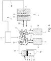
- a device 1 for performing the method according to the invention is shown schematically in FIG. 4 and has a temperature control device 2 with a heating device, at least one temperature control device 3 with a cooling device and an injection molding tool 4, actuators 5 and a control unit 6.
- the control unit 6 can have a regulating effect on the actuators 5, the control unit 6 processing signals as a function of a cavity wall temperature, which is determined, for example, by a temperature sensor 7 located in a cavity 8 of the injection molding tool 4.
- the temperature control device 2 with a heating device provides a relatively hot temperature control medium 9 in comparison to the temperature control device with a cooling device 3, which provides a relatively cold temperature control medium 10.
- the temperature control devices 2, 3 are connected to the actuators 5 via suitable pipelines (shown schematically by the arrows 11).
- the actuators 5 are connected to the injection molding tool 4 via suitable tubing or tubing (arrows 12).
- the injection molding tool 4 has at least one temperature control circuit 13 through which alternately hot temperature control medium 9 and cold temperature control medium 10 can be passed.
- the injection molding tool 4 it is also possible for the injection molding tool 4 to have two temperature control circuits 13 which are hydraulically separated from one another. One of the two temperature control circuits 13 serves to pass the cold temperature control medium 10 through, the other temperature control circuit serves to pass it through of the hot temperature control medium 9 through the injection molding tool 4 or an injection molding tool half.
- the device 1 preferably has a buffer 14 which holds a certain supply of hot temperature control medium 9 and a supply of cold temperature control medium 10.
- the buffer 14 is equipped with a displaceable piston element 15, which divides a buffer chamber into a partial space for hot temperature control medium 9 and a partial space for cold temperature control medium 10.
- the subspace containing hot temperature control medium 9 as well as the subspace containing cold temperature control medium 10 are each connected via suitable pipelines 16 to corresponding inputs of the actuators 5.
- By moving the piston 15 in the direction of the double arrow 17 an additional amount of cold temperature control medium 10 (movement of the piston 15 in Figure 4 down) or hot temperature control medium 9 (movement of the piston 15 in Figure 4 to the top) are fed into the temperature control circuits 13 via the actuators 5.
- the actuators 5 are, for example, an arrangement of different valves 18, which are only indicated schematically.
- the valves 18 are, for example, electrically controllable valves which are connected to the control unit 6 and can be controlled by it.
- either cold temperature control medium 10 or warm temperature control medium 9 can be fed into the temperature control circuits 13, whereby additional cold temperature control medium 10 or hot temperature control medium 9 can be fed in through buffer 14, for example to achieve high cooling or heating gradients.
- the provision of a buffer 14 makes it possible to use relatively small heating / cooling and / or pumping units for the temperature control devices 2, 3 and nevertheless to absorb syringe loads that occur in a learning and / or production cycle by means of the buffer 14. This helps to save energy and lowers the system costs.
- the temperature sensor 7 is connected to the control unit 6 via a suitable signal line 19. It is of course possible that a large number of temperature sensors 7 are arranged distributed over the cavity wall of the cavity 8 and send separate signals which represent a local cavity wall temperature to the control unit 6 or make them available to it.
- heating / cooling are also conceivable.
- electrical heating and / or cooling elements or gases can also be used as the temperature control medium.
- hot temperature control medium 9 is pumped through the cooling circuits 13 with a cool temperature control medium, the cavity wall of the cavity 8 will heat up.
- cold temperature control medium 10 is sent through the temperature control circuits 13.
- a method according to the invention for variothermal temperature control of the injection molding tool 4 is carried out in two phases, a learning phase A and a production phase B.
- learning phase A the temperature control characteristics of the system to be temperature controlled are determined, which at least include the injection molding tool 4, the temperature control devices 2, 3 and the corresponding (pipe) Line connections and the actuators 5 and the control unit 6 has.
- a temperature sensor 7 should be provided in the cavity 8 of the injection molding tool 4.
- This entire system which is to be temperature controlled (the injection mold 4) or to provide the temperature control (temperature control devices 2, 3, actuators 5 and the corresponding connections with the injection mold 4), has a certain temperature control characteristic, which, for example, is due to the shape of the cavity 8 is influenced in the injection mold 4. Further influencing variables can be the performance of the temperature control devices 2, 3 and the maximum possible flow rate of cold temperature control medium 10 and / or hot temperature control medium 9.
- Such a system made up of the above-mentioned components has a certain temperature control characteristic, that is, a certain temperature reaction of the cavity wall of the cavity 8 in the injection molding tool 4 takes place in response to a certain activity of the temperature control devices 2 or 3.
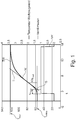
- Figure 1 shows a first partial step of this.
- the temperature control device 2 with heating device is switched on.
- the heating temperature control is switched on in the example shown according to Figure 1 at time t 1 .
- the graph VH (valve heating) is in Figure 1 and indicates a period of time in which the device 1 heats the injection molding tool.
- the graph TW indicates the temperature reaction on the cavity wall of the cavity 8, which is measured by the temperature sensor 7.
- the graph TW has an inflection point W in its course. To determine a characteristic variable for the temperature control characteristics of the system, it has proven useful to apply a tangent T to the graph TW at the turning point W.
- the maximum slope of the heating curve (graph TW) is present at the turning point W.
- the tangent forms an intersection point S with the abscissa.
- the period between the start of heating (time t 1 ) and the point of intersection S is defined as the delay time tu heat .
- the maximum slope of the tangent T is defined by a quotient of temperature and heating time, which is specified in "Kelvin per heating time (K / s heat )".
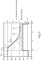
- the cooling characteristics of the injection molding tool 4 are determined analogously on the basis of a maximum achievable temperature T max (cf. Figure 2 ).
- a cooling curve (graph TK) is determined within the scope of determining the cooling characteristic, which can be reduced from the maximum injection mold temperature T max to a minimum achievable temperature T min .
- the temperature control device 2 warm temperature control device
- the temperature control device 3 with cool temperature control medium 10 is switched on.
- the activated cooling is shown with the graph VK.
- a tangent T is placed at the turning point W, the slope of which reflects the maximum cooling gradient. This cooling gradient can be specified in the unit Kelvin per cooling time (K / s cool ).
- This tangent also intersects the abscissa at the point of intersection S, so that a cooling delay time tu cool results, which results from the point in time t 1 (switching on the cooling unit) to the point of intersection S of the tangent T with the abscissa.
- This characterization of the heating and cooling behavior of the system is preferably carried out with an empty injection mold, that is to say still without any melt. As a result, it is not necessary to carry out the learning phase with an injection molding tool which is mounted on a plastic injection molding machine. Another advantage is that the use of plastic melt does not affect the mold temperature control characteristics or the system temperature control characteristics.
- the determined temperature control characteristics of the system are preferably stored in the form of tool-specific, in particular system-specific control values for actuators or otherwise assigned to the tool / system.
- a mean temperature T base can be calculated from this temperature control characteristic, for example by forming the difference between the maximum achievable temperature T max and the minimum achievable temperature T min.
- the process times t process1 for the heating case and the cooling case can be determined more precisely in order to achieve a setpoint temperature T setpoint1 based on a current injection mold temperature (cavity wall temperature T actMld ) as precisely as possible.
- the activation times of the heating device and / or the cooling device are corrected from one process to the next by corresponding start offset temperatures T startOffset or end temperature deviations T endOffset in order to include the start / end temperatures of the previous process at the beginning / end of one process consider.
- start offset temperatures T startOffest and T endOffset the corresponding offset times t startOffset and t endOffset can be determined for both heating and cooling.
- t startOffset T startOffset / K / s heat
- t endOffset T endOffset / K / s heat
- t startOffset T startOffset / K / s cool
- endOffset T endOffset / K / s cool
- the process time t process (x ) for the current process which is used for the current heating / cooling case. This enables learning for the current process from the ambient conditions and the sequence of the previous process.
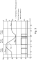
- the graph TW which indicates the mold temperature over time t, is in Figure 3 shown.
- Target temperatures T Soll1 and T Soll2 and T Soll3 are also specified.
- Switch-on times for the operation of the temperature control device 2 with a heating device and the temperature control device 3 with a cooling device are shown. Viewed from left to right, the temperature control device 2 with the heating device is switched on at a time t of approximately 10 seconds, so that the graph TW rises from this time (taking into account the time tu heat ) up to a setpoint temperature T 1 , which in Embodiment is approximately 109 °.
- the temperature of the injection molding tool 4 is kept approximately constant for a period of time.
- cooling begins by switching on the Temperature control device 3 with the cooling device, so that the tool is cooled from T Soll1 to a lower temperature T Soll2.
- T Soll3 a further target temperature
Landscapes
- Engineering & Computer Science (AREA)
- Manufacturing & Machinery (AREA)
- Mechanical Engineering (AREA)
- Physics & Mathematics (AREA)
- Health & Medical Sciences (AREA)
- Oral & Maxillofacial Surgery (AREA)
- Thermal Sciences (AREA)
- Injection Moulding Of Plastics Or The Like (AREA)
- Moulds For Moulding Plastics Or The Like (AREA)
Claims (22)
- Procédé de thermorégulation variothermique d'un outil de moulage par injection par utilisation d'un dispositif de mise en température présentant au moins les étapes suivantes :A) dans une phase d'apprentissage :- détermination d'une caractéristique de mise en température du système à mettre en température comprenant au moins l'outil de moulage par injection et le dispositif de mise en température pour obtenir des valeurs de réglage individuelles au système avec lesquelles des membres de réglage du dispositif de mise en température peuvent être commandés pour obtenir un profil de température de consigneB) dans une phase de production :- mise en température de l'outil de moulage par injection avec les valeurs de réglage déterminées dans la phase d'apprentissage ;- détermination d'écarts d'un profil de température réelle de l'outil de moulage par injection par rapport au profil de température de consigne pendant le cycle de production et calcul de valeurs de réglage corrigées pour les membres de réglage à partir de ces écarts ;- exécution d'un processus de production suivant avec les valeurs de réglage corrigées.
- Procédé selon la revendication 1, dans lequelA) dans la phase d'apprentissage :A1) pour déterminer une caractéristique de mise en température du système à mettre en température ;
un calcul de temps de commande est effectué pour des dispositifs de chauffage et/ou de refroidissement du dispositif de mise en température pour obtenir un profil de température de consigne temporel de l'outil de moulage par injection pour une pièce moulée à fabriquer ;A2) une évaluation du profil de température de consigne dans au moins un cycle d'évaluation est effectuée, et si besoin, correction des temps de commande etA3) un enregistrement au moins des temps de commande corrigés de l'étape A3) en tant que valeurs de réglage est effectué pour le système à mettre en température, en particulier de ses membres de réglage, etB) dans la phase de production :B1) pendant un premier cycle de production, un arrêt du profil de température est effectué avec les valeurs de réglage de l'étape A3),B2) une détermination des valeurs réelles et une comparaison avec des températures de consigne correspondantes du profil de température de consigne de l'outil de moulage par injection sont effectuées ;B3) un calcul de valeurs de réglage corrigées, à savoir des temps de réglage pour les membres de réglage du cycle de production suivant, est effectué à partir d'écarts calculés à l'étape B2) etB4) une exécution du cycle de production suivant avec les valeurs de réglage corrigées de l'étape B3) est effectuée etB5) les étapes B2) à B5) sont répétées pendant d'autres cycles de production. - Procédé selon la revendication 1 ou 2,
caractérisé en ce que
en tant que dispositifs de chauffage et/ou de refroidissement du dispositif de mise en température sont utilisés au moins un ou une combinaison du groupe :- dispositif de chauffage d'eau et/ou de refroidissement d'eau ;- dispositif de chauffage de fioul et/ou de refroidissement de fioul .- dispositif de chauffage électrique et/ou de refroidissement électrique ;- cartouches de chauffage et/ou de refroidissement ;- dispositifs de chauffage basés sur induction ou par laser ainsi que chauffages céramique ;- dispositifs de refroidissement par réfrigérants et/ou dispositifs de refroidissement au CO2 et/ou un refroidissement par un gaz, par ex. de l'air ;- dispositif de chauffage et/ou de refroidissement à base d'une huile caloporteuse et/ou de vapeur chaude. - Procédé selon l'une des revendications précédentes, caractérisé en ce que l'étape A est effectuée sans remplissage de l'outil de moulage par injection avec une matière à mouler.
- Procédé selon l'une des revendications précédentes, caractérisé en ce que pour déterminer la caractéristique de température du système à mettre en température composé au moins d'un dispositif de chauffage, d'un dispositif de refroidissement, de membres de réglage et d'un outil de moulage par injection, une température de paroi minimale (Tmin) pouvant être atteinte d'une cavité de l'outil de moulage par injection est déterminée et enregistrée.
- Procédé selon l'une des revendications précédentes, caractérisé en ce que pour déterminer la caractéristique de température du système à mettre en température composé au moins d'un dispositif de chauffage, d'un dispositif de refroidissement, de membres de réglage et d'un outil de moulage par injection, une température de paroi maximale (Tmax) pouvant être atteinte d'une cavité de l'outil de moulage par injection est déterminée et enregistrée.
- Procédé selon l'une des revendications précédentes, caractérisé en ce que pendant une opération de chauffage selon la revendication 5, la pente maximale d'une courbe de chauffage est déterminée en Kelvin par seconde (K/Sheat) à son point d'inflexion (W) .
- Procédé selon l'une des revendications précédentes, caractérisé en ce qu'au point d'inflexion de la courbe de chauffage, une tangente (T) est appliquée à la courbe de chauffage et un point d'intersection de la tangente (T) est formé avec l'abscisse, dans lequel l'écart temporel entre le début du chauffage et le point d'intersection de la tangente (T) avec l'abscisse est défini en tant que temps de retard (tuheat).
- Procédé selon l'une des revendications précédentes, caractérisé en ce qu'en partant de la température (Tmax), le refroidissement est démarré chauffage éteint, dans lequel une pente maximale négative (K/scool) est déterminée en Kelvin par seconde sur le point d'inflexion (W) de la courbe de refroidissement (TK) et une tangente (T) est appliquée au point d'intersection (W) de la courbe de refroidissement (TK), dans lequel le point d'intersection de la tangente (T) avec l'abscisse est déterminé et un temps de retard (tucool) est défini en tant qu'écart temporel entre le début du refroidissement et le point d'intersection de la tangente (T) avec l'abscisse.
- Procédé selon l'une des revendications précédentes, caractérisé en ce qu'une température moyenne (TBasis) est calculée entre la température minimale (Tmin) et la température maximale (Tmax).
- Procédé selon l'une des revendications précédentes, caractérisé en ce qu'en partant de la formule

- Procédé selon l'une des revendications précédentes, caractérisé en ce qu'après l'arrêt du chauffage, c'est-à-dire une fois le temps (tbasisheat) écoulé, une période temporelle est mesurée jusqu'à ce qu'il ne se produise plus aucun autre changement de température significatif sur le capteur de température (7), dans lequel une température (Tbasisheat) et un temps de postoscillation (temps de retard) (tBasisheatdead) sont mesurés et enregistrés.
- Procédé selon l'une des revendications précédentes, caractérisé en ce qu'un écart entre la température moyenne (TBasis) et la température (TBasisheat) est calculé selon la formule

- Procédé selon l'une des revendications précédentes, caractérisé en ce que le refroidissement est commandé pendant que le chauffage est à l'arrêt, jusqu'à ce que la température maximale (Tmax) soit atteinte sur le capteur de température (7), et à partir de la formule

- Procédé selon l'une des revendications précédentes, caractérisé en ce qu'en partant de la température maximale (Tmax) d'une étape d'apprentissage précédente, le refroidissement est commandé et coupé après le temps (tbasiscool) , dans lequel le temps jusqu'à ce que plus aucun changement de température significatif ne puisse être mesuré sur le capteur de température (7) dans la cavité (8) est ensuite mesuré, dans lequel la température (Tbasiscool) et le temps de postoscillation (temps de retard) (tBasiscooldead) sont mesurés et enregistrés et l'écart de (TBasis) à (TBasiscool) est calculé selon la formule

- Procédé selon l'une des revendications précédentes, caractérisé en ce que dans un déroulement de procédé pour au moins une étape de chauffage puisé ou au moins une étape de refroidissement pulsé, des temps de commande du dispositif de chauffage et/ou du dispositif de refroidissement sont mesurés et enregistrés en partant de la température actuelle de la paroi de cavité (TactMld), dans lequel la température de consigne (TSoll) est déterminée à partir de l'étape actuelle et lorsque la température de consigne (TSoll) est supérieure à la température (TactMld), le temps (tProzess1) est calculé dans une première passe d'optimisation, selon la formule

- Procédé selon l'une des revendications précédentes, caractérisé en ce que dans le cas où la température de consigne (TSoll) est inférieure à la température actuelle (TactMld), le temps (tProzess1) est calculé selon la formule

- Procédé selon l'une des revendications précédentes, caractérisé en ce que le calcul du temps (tProzess1) est effectué de manière analogue pour d'autres étapes de procédé.
- Procédé selon l'une des revendications précédentes, caractérisé en ce que le calcul du temps (tProzess1) est effectué de manière répétée pour un procédé de chauffage puisé ou pour un procédé de refroidissement pulsé.
- Procédé selon l'une des revendications précédentes, caractérisé en ce que pendant d'autres passes, les temps de commande du dispositif de chauffage et/ou du dispositif de refroidissement sont corrigés d'un écart de température de départ (TstartOffset) et/ou d'un écart de température de fin (TendOffset), dans lequel les formules listées ci-après sont utilisées


(n-1) est la température correspondante de la passe précédente. - Procédé selon l'une des revendications précédentes, caractérisé en ce que qu'un temps (tstartOffset) et (tendOffset) correspondant à l'écart de température de départ (TstartOffset) et/ou à l'écart de température de fin (TendOffset), est calculé en fonction du chauffage puisé (K/sheat) ou du refroidissement pulsé (K/scool), sachant que :pour le chauffage puisé :

 pour le refroidissement puisé :

- Procédé selon l'une des revendications précédentes, caractérisé en ce
qu'un temps de commande (tProzess(x)) pour un procédé de chauffage et/ou un procédé de refroidissement est déterminé à partir du temps de commande (tProzess(x-1)) venant du procédé précédent plus le temps (tstartOffset) à partir du procédé actuel plus le temps (tendOffset) venant du procédé précédent, ce qui peut être représenté sous forme de formule par :
Applications Claiming Priority (2)
| Application Number | Priority Date | Filing Date | Title |
|---|---|---|---|
| DE102017117587.3A DE102017117587A1 (de) | 2017-08-03 | 2017-08-03 | Verfahren und Vorrichtung zur variothermen Temperierung von Spritzgießwerkzeugen |
| PCT/EP2018/068465 WO2019025122A1 (fr) | 2017-08-03 | 2018-07-09 | Procédé et dispositif de thermorégulation variothermique d'outils de moulage par injection |
Publications (3)
| Publication Number | Publication Date |
|---|---|
| EP3661720A1 EP3661720A1 (fr) | 2020-06-10 |
| EP3661720B1 true EP3661720B1 (fr) | 2021-09-08 |
| EP3661720B2 EP3661720B2 (fr) | 2025-05-21 |
Family
ID=62873339
Family Applications (1)
| Application Number | Title | Priority Date | Filing Date |
|---|---|---|---|
| EP18739510.8A Active EP3661720B2 (fr) | 2017-08-03 | 2018-07-09 | Procédé de thermorégulation variothermique d'outils de moulage par injection |
Country Status (6)
| Country | Link |
|---|---|
| US (1) | US11433588B2 (fr) |
| EP (1) | EP3661720B2 (fr) |
| KR (1) | KR20200035422A (fr) |
| CN (1) | CN110997274B (fr) |
| DE (1) | DE102017117587A1 (fr) |
| WO (1) | WO2019025122A1 (fr) |
Families Citing this family (14)
| Publication number | Priority date | Publication date | Assignee | Title |
|---|---|---|---|---|
| WO2019111117A1 (fr) * | 2017-12-07 | 2019-06-13 | Green Box Srl | Dispositif ou circuit de régulation de température pour moules ou systèmes de moulage |
| FR3096293B1 (fr) | 2019-05-23 | 2024-02-02 | Inst De Rech Tech Jules Verne | Dispositif et procédé de fabrication d’une pièce en matériau composite |
| CN112622217B (zh) * | 2021-01-18 | 2022-10-04 | 苏州星诺奇科技股份有限公司 | 缩短带卡扣筒形注塑件成型周期的生产方法 |
| CN113059773B (zh) * | 2021-03-15 | 2022-12-13 | 伯乐智能装备股份有限公司 | 一种保证注塑制品重量稳定的注射方法 |
| CN113601806A (zh) * | 2021-06-29 | 2021-11-05 | 无锡有孚精工科技有限公司 | 一种模具生产用气液冷却装置、系统及方法 |
| KR102504881B1 (ko) * | 2022-03-07 | 2023-02-28 | 주식회사 제이시스 | 반응기의 온도제어방법 |
| CN114734604B (zh) * | 2022-03-28 | 2023-08-29 | 浙江凯华模具有限公司 | 一种注塑过程的模具温度在线控制方法 |
| TWI871608B (zh) * | 2023-04-06 | 2025-02-01 | 瑞皇精密工業股份有限公司 | 具可變模溫結構之模具 |
| KR102611604B1 (ko) * | 2023-08-24 | 2023-12-07 | 한경희 | 사출 성형기의 금형 온도 조절장치 |
| CN117400502B (zh) * | 2023-10-31 | 2024-06-14 | 惠州市信友实业有限公司 | 一种注塑机节能控制系统及控制方法 |
| CN118288512B (zh) * | 2024-06-06 | 2024-10-11 | 张家港市品杰模塑科技有限公司 | 一种塑料注塑模具的冷却控制方法及系统 |
| CN118849365B (zh) * | 2024-07-04 | 2025-04-04 | 广州市旭匠精密科技有限公司 | 一种基于精密注塑的模具温度控制系统及控制方法 |
| CN120620598B (zh) * | 2025-06-06 | 2025-12-12 | 东莞市润荣精密五金塑胶有限公司 | 用于注塑模具的温度控制优化方法及系统 |
| CN120985892B (zh) * | 2025-09-17 | 2026-04-10 | 武汉兴亿盛精密模具有限公司 | 一种汽车零部件模具区域温度控制方法 |
Citations (8)
| Publication number | Priority date | Publication date | Assignee | Title |
|---|---|---|---|---|
| US5427720A (en) | 1993-03-09 | 1995-06-27 | Kotzab; Werner | Method for mold temperature control |
| US5589114A (en) | 1990-11-16 | 1996-12-31 | Evans; Rowland F. | Temperature regulating system, method and apparatus |
| DE102004052499A1 (de) | 2004-10-28 | 2006-07-13 | Faurecia Innenraum Systeme Gmbh | Spritzgusswerkzeug und Elektronikmodul |
| US20070184139A1 (en) | 2004-02-12 | 2007-08-09 | Mitsubishi Heavy Industries, Ltd. | Mold temperature adjusting apparatus/method and mold temperature control unit |
| DE102006031268A1 (de) | 2006-07-06 | 2008-01-10 | Krauss Maffei Gmbh | Vorrichtung und Verfahren zur benutzerspezifischen Überwachung und Regelung der Produktion |
| DE102007019389A1 (de) * | 2007-04-23 | 2008-10-30 | Single Temperiertechnik Gmbh | Temperiersystem, Vorrichtung mit Temperiersystem und Verfahren zum Temperieren einer Vorrichtung sowie zur Herstellung der Vorrichtung |
| DE102008045006A1 (de) | 2008-08-29 | 2010-03-04 | Kraussmaffei Technologies Gmbh | Verfahren und Vorrichtung zur variothermen Temperierung von Spritzgießwerkzeugen |
| WO2011048376A1 (fr) * | 2009-10-20 | 2011-04-28 | Surface Generation Limited | Système de régulation pour l'usinage |
Family Cites Families (4)
| Publication number | Priority date | Publication date | Assignee | Title |
|---|---|---|---|---|
| AT396575B (de) | 1985-09-16 | 1993-10-25 | Engel Kg L | Verfahren zur werkzeugtemperierung für die formwerkzeuge von spritzgiessmaschinen |
| JPH04119814A (ja) | 1990-09-10 | 1992-04-21 | Nissei Plastics Ind Co | 射出成形機の温度制御方法 |
| US5376317A (en) * | 1992-12-08 | 1994-12-27 | Galic Maus Ventures | Precision surface-replicating thermoplastic injection molding method and apparatus, using a heating phase and a cooling phase in each molding cycle |
| DE4436117C2 (de) * | 1994-09-27 | 1997-10-02 | Riesselmann F & H Kunststoff | Verfahren zur Temperierung von Spritzgießmaschineneinheiten und Formwerkzeugeinheiten für die Kunststoffverarbeitung |
-
2017
- 2017-08-03 DE DE102017117587.3A patent/DE102017117587A1/de active Pending
-
2018
- 2018-07-09 KR KR1020207005078A patent/KR20200035422A/ko not_active Abandoned
- 2018-07-09 US US16/632,959 patent/US11433588B2/en active Active
- 2018-07-09 CN CN201880048428.XA patent/CN110997274B/zh active Active
- 2018-07-09 WO PCT/EP2018/068465 patent/WO2019025122A1/fr not_active Ceased
- 2018-07-09 EP EP18739510.8A patent/EP3661720B2/fr active Active
Patent Citations (9)
| Publication number | Priority date | Publication date | Assignee | Title |
|---|---|---|---|---|
| US5589114A (en) | 1990-11-16 | 1996-12-31 | Evans; Rowland F. | Temperature regulating system, method and apparatus |
| US5427720A (en) | 1993-03-09 | 1995-06-27 | Kotzab; Werner | Method for mold temperature control |
| US5427720C1 (en) | 1993-03-09 | 2001-01-30 | Werner Kotzab | Method for mold temperature control |
| US20070184139A1 (en) | 2004-02-12 | 2007-08-09 | Mitsubishi Heavy Industries, Ltd. | Mold temperature adjusting apparatus/method and mold temperature control unit |
| DE102004052499A1 (de) | 2004-10-28 | 2006-07-13 | Faurecia Innenraum Systeme Gmbh | Spritzgusswerkzeug und Elektronikmodul |
| DE102006031268A1 (de) | 2006-07-06 | 2008-01-10 | Krauss Maffei Gmbh | Vorrichtung und Verfahren zur benutzerspezifischen Überwachung und Regelung der Produktion |
| DE102007019389A1 (de) * | 2007-04-23 | 2008-10-30 | Single Temperiertechnik Gmbh | Temperiersystem, Vorrichtung mit Temperiersystem und Verfahren zum Temperieren einer Vorrichtung sowie zur Herstellung der Vorrichtung |
| DE102008045006A1 (de) | 2008-08-29 | 2010-03-04 | Kraussmaffei Technologies Gmbh | Verfahren und Vorrichtung zur variothermen Temperierung von Spritzgießwerkzeugen |
| WO2011048376A1 (fr) * | 2009-10-20 | 2011-04-28 | Surface Generation Limited | Système de régulation pour l'usinage |
Also Published As
| Publication number | Publication date |
|---|---|
| EP3661720B2 (fr) | 2025-05-21 |
| US11433588B2 (en) | 2022-09-06 |
| CN110997274A (zh) | 2020-04-10 |
| CN110997274B (zh) | 2022-04-05 |
| DE102017117587A1 (de) | 2019-02-07 |
| KR20200035422A (ko) | 2020-04-03 |
| EP3661720A1 (fr) | 2020-06-10 |
| WO2019025122A9 (fr) | 2020-03-12 |
| WO2019025122A1 (fr) | 2019-02-07 |
| US20200156301A1 (en) | 2020-05-21 |
Similar Documents
| Publication | Publication Date | Title |
|---|---|---|
| EP3661720B1 (fr) | Procédé de thermorégulation variothermique d'outils de moulage par injection | |
| DE2253506C3 (de) | Regeleinrichtung für die Einspritzeinheit einer Schnecken-Spritzgießmaschine | |
| DE69936385T2 (de) | Automatische formtechnik für thermoplastisches spritzgiessen | |
| EP2583811B1 (fr) | Procédé de quantification de basculements de procédés dans le cadre d'un processus d'injection d'une machine de moulage par injection | |
| DE102011078167B4 (de) | Verfahren zur Temperierung eines Spritzgießwerkzeugs | |
| DE112011100051T5 (de) | Gießverfahren einer Spritzgießmaschine | |
| DE102009005142A1 (de) | Streckblasmaschine mit beheizbarer Blasform | |
| EP0704293A2 (fr) | Procédé de régulation en température d'unités d'injection et de moules d'injection de matières plastiques | |
| EP2427319B1 (fr) | Unité de commande pour presse à injecter | |
| DE102014014525A1 (de) | Spritzgiesssystem, das Druckabnormalitäten erkennen kann | |
| AT516167B1 (de) | Temperiervorrichtung zum variothermen oder konventionellen Temperieren von Formwerkzeugen | |
| WO1994022656A1 (fr) | Procede et installation d'adaptation de la temperature d'outils de moulage pour matieres plastiques | |
| DE102016101523A1 (de) | System und Verfahren zum Spritzgießen von Kunststoffen | |
| DE102014014231A1 (de) | Verfahren zur Bestimmung eines Sollwerts für einen Einstellparameter | |
| DE102010024267A1 (de) | Verfahren zur Herstellung von Kunststoff-Formteilen | |
| DE102015008371A1 (de) | Verfahren und Vorrichtung zur Temperierung eines Formwerkzeugs | |
| EP1888316B1 (fr) | Procede de regulation du processus de moulage par injection d'une machine de moulage par injection | |
| DE4436117C2 (de) | Verfahren zur Temperierung von Spritzgießmaschineneinheiten und Formwerkzeugeinheiten für die Kunststoffverarbeitung | |
| WO2025021804A1 (fr) | Procédé de réglage et de fonctionnement de machines de traitement de matières plastiques, et machine associée | |
| EP3808531B1 (fr) | Procédé de conduite d'une buse de vanne à pointeau | |
| DE10160903B4 (de) | Verfahren zur Kühlung von Formwerkzeugen bei der Herstellung von Kunststoff-Spritzgussteilen | |
| EP2298530B1 (fr) | Dispositif et procédé destinés à tempérer un outil de moulage par injection | |
| DE102020114448A1 (de) | Verfahren und vorrichtung zum herstellen eines extrudierten produkts | |
| EP2615518B1 (fr) | Procédé de mise en temperature et de régulation de la température d'un outil de fabrication chauffé par un fluide en phase liquide et/ou vapeur | |
| DE102020117665A1 (de) | Phasenvereinende, modellbasierte, prädiktive Regelung einer Spritzgießmaschine sowie Spritzgießmaschine mit einer derartigen Regelung |
Legal Events
| Date | Code | Title | Description |
|---|---|---|---|
| STAA | Information on the status of an ep patent application or granted ep patent |
Free format text: STATUS: UNKNOWN |
|
| STAA | Information on the status of an ep patent application or granted ep patent |
Free format text: STATUS: THE INTERNATIONAL PUBLICATION HAS BEEN MADE |
|
| PUAI | Public reference made under article 153(3) epc to a published international application that has entered the european phase |
Free format text: ORIGINAL CODE: 0009012 |
|
| STAA | Information on the status of an ep patent application or granted ep patent |
Free format text: STATUS: REQUEST FOR EXAMINATION WAS MADE |
|
| 17P | Request for examination filed |
Effective date: 20200303 |
|
| AK | Designated contracting states |
Kind code of ref document: A1 Designated state(s): AL AT BE BG CH CY CZ DE DK EE ES FI FR GB GR HR HU IE IS IT LI LT LU LV MC MK MT NL NO PL PT RO RS SE SI SK SM TR |
|
| AX | Request for extension of the european patent |
Extension state: BA ME |
|
| DAV | Request for validation of the european patent (deleted) | ||
| DAX | Request for extension of the european patent (deleted) | ||
| TPAC | Observations filed by third parties |
Free format text: ORIGINAL CODE: EPIDOSNTIPA |
|
| GRAP | Despatch of communication of intention to grant a patent |
Free format text: ORIGINAL CODE: EPIDOSNIGR1 |
|
| STAA | Information on the status of an ep patent application or granted ep patent |
Free format text: STATUS: GRANT OF PATENT IS INTENDED |
|
| INTG | Intention to grant announced |
Effective date: 20210316 |
|
| GRAS | Grant fee paid |
Free format text: ORIGINAL CODE: EPIDOSNIGR3 |
|
| GRAA | (expected) grant |
Free format text: ORIGINAL CODE: 0009210 |
|
| STAA | Information on the status of an ep patent application or granted ep patent |
Free format text: STATUS: THE PATENT HAS BEEN GRANTED |
|
| AK | Designated contracting states |
Kind code of ref document: B1 Designated state(s): AL AT BE BG CH CY CZ DE DK EE ES FI FR GB GR HR HU IE IS IT LI LT LU LV MC MK MT NL NO PL PT RO RS SE SI SK SM TR |
|
| REG | Reference to a national code |
Ref country code: GB Ref legal event code: FG4D Free format text: NOT ENGLISH |
|
| REG | Reference to a national code |
Ref country code: AT Ref legal event code: REF Ref document number: 1428190 Country of ref document: AT Kind code of ref document: T Effective date: 20210915 Ref country code: CH Ref legal event code: EP |
|
| REG | Reference to a national code |
Ref country code: IE Ref legal event code: FG4D Free format text: LANGUAGE OF EP DOCUMENT: GERMAN |
|
| REG | Reference to a national code |
Ref country code: DE Ref legal event code: R096 Ref document number: 502018006987 Country of ref document: DE |
|
| REG | Reference to a national code |
Ref country code: LT Ref legal event code: MG9D |
|
| REG | Reference to a national code |
Ref country code: NL Ref legal event code: MP Effective date: 20210908 |
|
| PG25 | Lapsed in a contracting state [announced via postgrant information from national office to epo] |
Ref country code: NO Free format text: LAPSE BECAUSE OF FAILURE TO SUBMIT A TRANSLATION OF THE DESCRIPTION OR TO PAY THE FEE WITHIN THE PRESCRIBED TIME-LIMIT Effective date: 20211208 Ref country code: LT Free format text: LAPSE BECAUSE OF FAILURE TO SUBMIT A TRANSLATION OF THE DESCRIPTION OR TO PAY THE FEE WITHIN THE PRESCRIBED TIME-LIMIT Effective date: 20210908 Ref country code: BG Free format text: LAPSE BECAUSE OF FAILURE TO SUBMIT A TRANSLATION OF THE DESCRIPTION OR TO PAY THE FEE WITHIN THE PRESCRIBED TIME-LIMIT Effective date: 20211208 Ref country code: SE Free format text: LAPSE BECAUSE OF FAILURE TO SUBMIT A TRANSLATION OF THE DESCRIPTION OR TO PAY THE FEE WITHIN THE PRESCRIBED TIME-LIMIT Effective date: 20210908 Ref country code: RS Free format text: LAPSE BECAUSE OF FAILURE TO SUBMIT A TRANSLATION OF THE DESCRIPTION OR TO PAY THE FEE WITHIN THE PRESCRIBED TIME-LIMIT Effective date: 20210908 Ref country code: HR Free format text: LAPSE BECAUSE OF FAILURE TO SUBMIT A TRANSLATION OF THE DESCRIPTION OR TO PAY THE FEE WITHIN THE PRESCRIBED TIME-LIMIT Effective date: 20210908 Ref country code: FI Free format text: LAPSE BECAUSE OF FAILURE TO SUBMIT A TRANSLATION OF THE DESCRIPTION OR TO PAY THE FEE WITHIN THE PRESCRIBED TIME-LIMIT Effective date: 20210908 Ref country code: ES Free format text: LAPSE BECAUSE OF FAILURE TO SUBMIT A TRANSLATION OF THE DESCRIPTION OR TO PAY THE FEE WITHIN THE PRESCRIBED TIME-LIMIT Effective date: 20210908 |
|
| PG25 | Lapsed in a contracting state [announced via postgrant information from national office to epo] |
Ref country code: LV Free format text: LAPSE BECAUSE OF FAILURE TO SUBMIT A TRANSLATION OF THE DESCRIPTION OR TO PAY THE FEE WITHIN THE PRESCRIBED TIME-LIMIT Effective date: 20210908 Ref country code: GR Free format text: LAPSE BECAUSE OF FAILURE TO SUBMIT A TRANSLATION OF THE DESCRIPTION OR TO PAY THE FEE WITHIN THE PRESCRIBED TIME-LIMIT Effective date: 20211209 |
|
| PG25 | Lapsed in a contracting state [announced via postgrant information from national office to epo] |
Ref country code: IS Free format text: LAPSE BECAUSE OF FAILURE TO SUBMIT A TRANSLATION OF THE DESCRIPTION OR TO PAY THE FEE WITHIN THE PRESCRIBED TIME-LIMIT Effective date: 20220108 Ref country code: SM Free format text: LAPSE BECAUSE OF FAILURE TO SUBMIT A TRANSLATION OF THE DESCRIPTION OR TO PAY THE FEE WITHIN THE PRESCRIBED TIME-LIMIT Effective date: 20210908 Ref country code: SK Free format text: LAPSE BECAUSE OF FAILURE TO SUBMIT A TRANSLATION OF THE DESCRIPTION OR TO PAY THE FEE WITHIN THE PRESCRIBED TIME-LIMIT Effective date: 20210908 Ref country code: RO Free format text: LAPSE BECAUSE OF FAILURE TO SUBMIT A TRANSLATION OF THE DESCRIPTION OR TO PAY THE FEE WITHIN THE PRESCRIBED TIME-LIMIT Effective date: 20210908 Ref country code: PT Free format text: LAPSE BECAUSE OF FAILURE TO SUBMIT A TRANSLATION OF THE DESCRIPTION OR TO PAY THE FEE WITHIN THE PRESCRIBED TIME-LIMIT Effective date: 20220110 Ref country code: PL Free format text: LAPSE BECAUSE OF FAILURE TO SUBMIT A TRANSLATION OF THE DESCRIPTION OR TO PAY THE FEE WITHIN THE PRESCRIBED TIME-LIMIT Effective date: 20210908 Ref country code: NL Free format text: LAPSE BECAUSE OF FAILURE TO SUBMIT A TRANSLATION OF THE DESCRIPTION OR TO PAY THE FEE WITHIN THE PRESCRIBED TIME-LIMIT Effective date: 20210908 Ref country code: EE Free format text: LAPSE BECAUSE OF FAILURE TO SUBMIT A TRANSLATION OF THE DESCRIPTION OR TO PAY THE FEE WITHIN THE PRESCRIBED TIME-LIMIT Effective date: 20210908 Ref country code: CZ Free format text: LAPSE BECAUSE OF FAILURE TO SUBMIT A TRANSLATION OF THE DESCRIPTION OR TO PAY THE FEE WITHIN THE PRESCRIBED TIME-LIMIT Effective date: 20210908 Ref country code: AL Free format text: LAPSE BECAUSE OF FAILURE TO SUBMIT A TRANSLATION OF THE DESCRIPTION OR TO PAY THE FEE WITHIN THE PRESCRIBED TIME-LIMIT Effective date: 20210908 |
|
| REG | Reference to a national code |
Ref country code: DE Ref legal event code: R026 Ref document number: 502018006987 Country of ref document: DE |
|
| PLBI | Opposition filed |
Free format text: ORIGINAL CODE: 0009260 |
|
| PLAX | Notice of opposition and request to file observation + time limit sent |
Free format text: ORIGINAL CODE: EPIDOSNOBS2 |
|
| 26 | Opposition filed |
Opponent name: SURFACE GENERATION LIMITED Effective date: 20220607 |
|
| PG25 | Lapsed in a contracting state [announced via postgrant information from national office to epo] |
Ref country code: DK Free format text: LAPSE BECAUSE OF FAILURE TO SUBMIT A TRANSLATION OF THE DESCRIPTION OR TO PAY THE FEE WITHIN THE PRESCRIBED TIME-LIMIT Effective date: 20210908 |
|
| PG25 | Lapsed in a contracting state [announced via postgrant information from national office to epo] |
Ref country code: SI Free format text: LAPSE BECAUSE OF FAILURE TO SUBMIT A TRANSLATION OF THE DESCRIPTION OR TO PAY THE FEE WITHIN THE PRESCRIBED TIME-LIMIT Effective date: 20210908 |
|
| PLBB | Reply of patent proprietor to notice(s) of opposition received |
Free format text: ORIGINAL CODE: EPIDOSNOBS3 |
|
| PG25 | Lapsed in a contracting state [announced via postgrant information from national office to epo] |
Ref country code: MC Free format text: LAPSE BECAUSE OF FAILURE TO SUBMIT A TRANSLATION OF THE DESCRIPTION OR TO PAY THE FEE WITHIN THE PRESCRIBED TIME-LIMIT Effective date: 20210908 |
|
| GBPC | Gb: european patent ceased through non-payment of renewal fee |
Effective date: 20220709 |
|
| REG | Reference to a national code |
Ref country code: BE Ref legal event code: MM Effective date: 20220731 |
|
| PG25 | Lapsed in a contracting state [announced via postgrant information from national office to epo] |
Ref country code: LU Free format text: LAPSE BECAUSE OF NON-PAYMENT OF DUE FEES Effective date: 20220709 |
|
| PG25 | Lapsed in a contracting state [announced via postgrant information from national office to epo] |
Ref country code: GB Free format text: LAPSE BECAUSE OF NON-PAYMENT OF DUE FEES Effective date: 20220709 Ref country code: BE Free format text: LAPSE BECAUSE OF NON-PAYMENT OF DUE FEES Effective date: 20220731 |
|
| PG25 | Lapsed in a contracting state [announced via postgrant information from national office to epo] |
Ref country code: IE Free format text: LAPSE BECAUSE OF NON-PAYMENT OF DUE FEES Effective date: 20220709 |
|
| PG25 | Lapsed in a contracting state [announced via postgrant information from national office to epo] |
Ref country code: MK Free format text: LAPSE BECAUSE OF FAILURE TO SUBMIT A TRANSLATION OF THE DESCRIPTION OR TO PAY THE FEE WITHIN THE PRESCRIBED TIME-LIMIT Effective date: 20210908 Ref country code: CY Free format text: LAPSE BECAUSE OF FAILURE TO SUBMIT A TRANSLATION OF THE DESCRIPTION OR TO PAY THE FEE WITHIN THE PRESCRIBED TIME-LIMIT Effective date: 20210908 |
|
| PG25 | Lapsed in a contracting state [announced via postgrant information from national office to epo] |
Ref country code: HU Free format text: LAPSE BECAUSE OF FAILURE TO SUBMIT A TRANSLATION OF THE DESCRIPTION OR TO PAY THE FEE WITHIN THE PRESCRIBED TIME-LIMIT; INVALID AB INITIO Effective date: 20180709 |
|
| PG25 | Lapsed in a contracting state [announced via postgrant information from national office to epo] |
Ref country code: MT Free format text: LAPSE BECAUSE OF FAILURE TO SUBMIT A TRANSLATION OF THE DESCRIPTION OR TO PAY THE FEE WITHIN THE PRESCRIBED TIME-LIMIT Effective date: 20210908 |
|
| PUAH | Patent maintained in amended form |
Free format text: ORIGINAL CODE: 0009272 |
|
| STAA | Information on the status of an ep patent application or granted ep patent |
Free format text: STATUS: PATENT MAINTAINED AS AMENDED |
|
| 27A | Patent maintained in amended form |
Effective date: 20250521 |
|
| AK | Designated contracting states |
Kind code of ref document: B2 Designated state(s): AL AT BE BG CH CY CZ DE DK EE ES FI FR GB GR HR HU IE IS IT LI LT LU LV MC MK MT NL NO PL PT RO RS SE SI SK SM TR |
|
| REG | Reference to a national code |
Ref country code: DE Ref legal event code: R102 Ref document number: 502018006987 Country of ref document: DE |
|
| PGFP | Annual fee paid to national office [announced via postgrant information from national office to epo] |
Ref country code: DE Payment date: 20250722 Year of fee payment: 8 |
|
| PGFP | Annual fee paid to national office [announced via postgrant information from national office to epo] |
Ref country code: IT Payment date: 20250724 Year of fee payment: 8 |
|
| PGFP | Annual fee paid to national office [announced via postgrant information from national office to epo] |
Ref country code: FR Payment date: 20250725 Year of fee payment: 8 Ref country code: AT Payment date: 20250722 Year of fee payment: 8 |
|
| PGFP | Annual fee paid to national office [announced via postgrant information from national office to epo] |
Ref country code: CH Payment date: 20250801 Year of fee payment: 8 |
|
| PG25 | Lapsed in a contracting state [announced via postgrant information from national office to epo] |
Ref country code: TR Free format text: LAPSE BECAUSE OF FAILURE TO SUBMIT A TRANSLATION OF THE DESCRIPTION OR TO PAY THE FEE WITHIN THE PRESCRIBED TIME-LIMIT Effective date: 20210908 |