EP2616523B1 - Substances luminescentes de silicophosphate - Google Patents
Substances luminescentes de silicophosphate Download PDFInfo
- Publication number
- EP2616523B1 EP2616523B1 EP11751816.7A EP11751816A EP2616523B1 EP 2616523 B1 EP2616523 B1 EP 2616523B1 EP 11751816 A EP11751816 A EP 11751816A EP 2616523 B1 EP2616523 B1 EP 2616523B1
- Authority
- EP
- European Patent Office
- Prior art keywords
- phosphor
- range
- compound
- mixture
- formula
- Prior art date
- Legal status (The legal status is an assumption and is not a legal conclusion. Google has not performed a legal analysis and makes no representation as to the accuracy of the status listed.)
- Not-in-force
Links
Images





Classifications
-
- C—CHEMISTRY; METALLURGY
- C09—DYES; PAINTS; POLISHES; NATURAL RESINS; ADHESIVES; COMPOSITIONS NOT OTHERWISE PROVIDED FOR; APPLICATIONS OF MATERIALS NOT OTHERWISE PROVIDED FOR
- C09K—MATERIALS FOR MISCELLANEOUS APPLICATIONS, NOT PROVIDED FOR ELSEWHERE
- C09K11/00—Luminescent materials, e.g. electroluminescent or chemiluminescent
- C09K11/08—Luminescent materials, e.g. electroluminescent or chemiluminescent containing inorganic luminescent materials
- C09K11/77—Luminescent materials, e.g. electroluminescent or chemiluminescent containing inorganic luminescent materials containing rare earth metals
- C09K11/7728—Luminescent materials, e.g. electroluminescent or chemiluminescent containing inorganic luminescent materials containing rare earth metals containing europium
- C09K11/7734—Aluminates
-
- C—CHEMISTRY; METALLURGY
- C09—DYES; PAINTS; POLISHES; NATURAL RESINS; ADHESIVES; COMPOSITIONS NOT OTHERWISE PROVIDED FOR; APPLICATIONS OF MATERIALS NOT OTHERWISE PROVIDED FOR
- C09K—MATERIALS FOR MISCELLANEOUS APPLICATIONS, NOT PROVIDED FOR ELSEWHERE
- C09K11/00—Luminescent materials, e.g. electroluminescent or chemiluminescent
- C09K11/08—Luminescent materials, e.g. electroluminescent or chemiluminescent containing inorganic luminescent materials
- C09K11/0883—Arsenides; Nitrides; Phosphides
-
- C—CHEMISTRY; METALLURGY
- C09—DYES; PAINTS; POLISHES; NATURAL RESINS; ADHESIVES; COMPOSITIONS NOT OTHERWISE PROVIDED FOR; APPLICATIONS OF MATERIALS NOT OTHERWISE PROVIDED FOR
- C09K—MATERIALS FOR MISCELLANEOUS APPLICATIONS, NOT PROVIDED FOR ELSEWHERE
- C09K11/00—Luminescent materials, e.g. electroluminescent or chemiluminescent
- C09K11/08—Luminescent materials, e.g. electroluminescent or chemiluminescent containing inorganic luminescent materials
- C09K11/59—Luminescent materials, e.g. electroluminescent or chemiluminescent containing inorganic luminescent materials containing silicon
-
- C—CHEMISTRY; METALLURGY
- C09—DYES; PAINTS; POLISHES; NATURAL RESINS; ADHESIVES; COMPOSITIONS NOT OTHERWISE PROVIDED FOR; APPLICATIONS OF MATERIALS NOT OTHERWISE PROVIDED FOR
- C09K—MATERIALS FOR MISCELLANEOUS APPLICATIONS, NOT PROVIDED FOR ELSEWHERE
- C09K11/00—Luminescent materials, e.g. electroluminescent or chemiluminescent
- C09K11/08—Luminescent materials, e.g. electroluminescent or chemiluminescent containing inorganic luminescent materials
- C09K11/70—Luminescent materials, e.g. electroluminescent or chemiluminescent containing inorganic luminescent materials containing phosphorus
- C09K11/71—Luminescent materials, e.g. electroluminescent or chemiluminescent containing inorganic luminescent materials containing phosphorus also containing alkaline earth metals
- C09K11/712—Halogenides
-
- C—CHEMISTRY; METALLURGY
- C09—DYES; PAINTS; POLISHES; NATURAL RESINS; ADHESIVES; COMPOSITIONS NOT OTHERWISE PROVIDED FOR; APPLICATIONS OF MATERIALS NOT OTHERWISE PROVIDED FOR
- C09K—MATERIALS FOR MISCELLANEOUS APPLICATIONS, NOT PROVIDED FOR ELSEWHERE
- C09K11/00—Luminescent materials, e.g. electroluminescent or chemiluminescent
- C09K11/08—Luminescent materials, e.g. electroluminescent or chemiluminescent containing inorganic luminescent materials
- C09K11/77—Luminescent materials, e.g. electroluminescent or chemiluminescent containing inorganic luminescent materials containing rare earth metals
- C09K11/7728—Luminescent materials, e.g. electroluminescent or chemiluminescent containing inorganic luminescent materials containing rare earth metals containing europium
- C09K11/77347—Silicon Nitrides or Silicon Oxynitrides
-
- C—CHEMISTRY; METALLURGY
- C09—DYES; PAINTS; POLISHES; NATURAL RESINS; ADHESIVES; COMPOSITIONS NOT OTHERWISE PROVIDED FOR; APPLICATIONS OF MATERIALS NOT OTHERWISE PROVIDED FOR
- C09K—MATERIALS FOR MISCELLANEOUS APPLICATIONS, NOT PROVIDED FOR ELSEWHERE
- C09K11/00—Luminescent materials, e.g. electroluminescent or chemiluminescent
- C09K11/08—Luminescent materials, e.g. electroluminescent or chemiluminescent containing inorganic luminescent materials
- C09K11/77—Luminescent materials, e.g. electroluminescent or chemiluminescent containing inorganic luminescent materials containing rare earth metals
- C09K11/7728—Luminescent materials, e.g. electroluminescent or chemiluminescent containing inorganic luminescent materials containing rare earth metals containing europium
- C09K11/77348—Silicon Aluminium Nitrides or Silicon Aluminium Oxynitrides
-
- C—CHEMISTRY; METALLURGY
- C09—DYES; PAINTS; POLISHES; NATURAL RESINS; ADHESIVES; COMPOSITIONS NOT OTHERWISE PROVIDED FOR; APPLICATIONS OF MATERIALS NOT OTHERWISE PROVIDED FOR
- C09K—MATERIALS FOR MISCELLANEOUS APPLICATIONS, NOT PROVIDED FOR ELSEWHERE
- C09K11/00—Luminescent materials, e.g. electroluminescent or chemiluminescent
- C09K11/08—Luminescent materials, e.g. electroluminescent or chemiluminescent containing inorganic luminescent materials
- C09K11/77—Luminescent materials, e.g. electroluminescent or chemiluminescent containing inorganic luminescent materials containing rare earth metals
- C09K11/7783—Luminescent materials, e.g. electroluminescent or chemiluminescent containing inorganic luminescent materials containing rare earth metals containing two or more rare earth metals one of which being europium
- C09K11/7792—Aluminates
-
- C—CHEMISTRY; METALLURGY
- C09—DYES; PAINTS; POLISHES; NATURAL RESINS; ADHESIVES; COMPOSITIONS NOT OTHERWISE PROVIDED FOR; APPLICATIONS OF MATERIALS NOT OTHERWISE PROVIDED FOR
- C09K—MATERIALS FOR MISCELLANEOUS APPLICATIONS, NOT PROVIDED FOR ELSEWHERE
- C09K11/00—Luminescent materials, e.g. electroluminescent or chemiluminescent
- C09K11/08—Luminescent materials, e.g. electroluminescent or chemiluminescent containing inorganic luminescent materials
- C09K11/77—Luminescent materials, e.g. electroluminescent or chemiluminescent containing inorganic luminescent materials containing rare earth metals
- C09K11/7783—Luminescent materials, e.g. electroluminescent or chemiluminescent containing inorganic luminescent materials containing rare earth metals containing two or more rare earth metals one of which being europium
- C09K11/77922—Silicates
-
- C—CHEMISTRY; METALLURGY
- C09—DYES; PAINTS; POLISHES; NATURAL RESINS; ADHESIVES; COMPOSITIONS NOT OTHERWISE PROVIDED FOR; APPLICATIONS OF MATERIALS NOT OTHERWISE PROVIDED FOR
- C09K—MATERIALS FOR MISCELLANEOUS APPLICATIONS, NOT PROVIDED FOR ELSEWHERE
- C09K11/00—Luminescent materials, e.g. electroluminescent or chemiluminescent
- C09K11/08—Luminescent materials, e.g. electroluminescent or chemiluminescent containing inorganic luminescent materials
- C09K11/77—Luminescent materials, e.g. electroluminescent or chemiluminescent containing inorganic luminescent materials containing rare earth metals
- C09K11/7783—Luminescent materials, e.g. electroluminescent or chemiluminescent containing inorganic luminescent materials containing rare earth metals containing two or more rare earth metals one of which being europium
- C09K11/7795—Phosphates
- C09K11/7796—Phosphates with alkaline earth metals
-
- F—MECHANICAL ENGINEERING; LIGHTING; HEATING; WEAPONS; BLASTING
- F21—LIGHTING
- F21V—FUNCTIONAL FEATURES OR DETAILS OF LIGHTING DEVICES OR SYSTEMS THEREOF; STRUCTURAL COMBINATIONS OF LIGHTING DEVICES WITH OTHER ARTICLES, NOT OTHERWISE PROVIDED FOR
- F21V9/00—Elements for modifying spectral properties, polarisation or intensity of the light emitted, e.g. filters
- F21V9/30—Elements containing photoluminescent material distinct from or spaced from the light source
-
- H—ELECTRICITY
- H10—SEMICONDUCTOR DEVICES; ELECTRIC SOLID-STATE DEVICES NOT OTHERWISE PROVIDED FOR
- H10H—INORGANIC LIGHT-EMITTING SEMICONDUCTOR DEVICES HAVING POTENTIAL BARRIERS
- H10H20/00—Individual inorganic light-emitting semiconductor devices having potential barriers, e.g. light-emitting diodes [LED]
- H10H20/80—Constructional details
- H10H20/85—Packages
- H10H20/851—Wavelength conversion means
- H10H20/8511—Wavelength conversion means characterised by their material, e.g. binder
- H10H20/8512—Wavelength conversion materials
Definitions
- the invention relates to silicophosphate compounds, processes for the preparation of these compounds and their use as conversion phosphors or, in bulbs.
- Inorganic phosphors are used in fluorescent light sources, emissive screens and as scintillator crystals or ceramics for the conversion of non-visible radiation or high energy particles into visible light.
- Classes of materials which have become widely used for this purpose are the Ce 3+ doped garnets of general composition (Y 1 -xyz Gd x Lu y Tb z ) 3 (Al 1-ab Ga a Sc b ) 5 O 12 : Ce w , wherein the VAriation of the composition for spectrum optimization, stability, the decay time and / or to avoid claims can be used.
- Ce 3+ or Eu 2+ doped nitrides and oxynitrides are currently the focus of attention here, since these actiVators show luminescence in the green to red spectral range due to the high zentroid shift in these host lattices, while in most purely oxidic materials both Ce 3+ and Eu 2+ luminesce especially in the UV or in the blue spectral range.
- Phosphors based on the eulytine structure were first reported by G.Blasse described [J. Sol. State Chem. 2, 27-30 (1970 )]. However, only compounds doped with Eu3 + or Ce3 + have been studied so far. However, these are not suitable for the excitation with blue LEDs.
- the object of the present invention was to develop silicophosphate phosphors which have a yellow-orange luminescence and are particularly suitable for use in high-power pcLEDs for producing cold-white light.
- Eu2 + doped alkaline earth-luthetium-containing silicophosphate phosphors meet the above-mentioned object. Due to the very broad fluorescence band and the color point these phosphors are particularly suitable for the production of cold white light. They are distinguished from the known Ba 2 Y 2 (PO 4 ) 2 (SiO 4 ) phosphors doped with Eu 3+ or Ce 3+ by the higher absorption strength in the blue spectral range.
- x is a value in the range 0.05 to 0.5 and particularly preferably in the range 0.1 to 0.3.
- a is a value from the range 0 to 0.5, particularly preferably from the range 0 to 0.2.
- b stands for a value from the range 0 ⁇ b ⁇ 0.1.
- c and d independently represent a value in the range of 0 to 0.8.
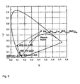
- LED quality is described using common parameters, such as the Color Rendering Index or the color point in CIE x and CIE y coordinates.
- the Color Rendering Index is a unitary photometric quantity known to those skilled in the art that compares the color fidelity of an artificial light source to that of sunlight or filament light sources (the latter two have a CRI of 100).
- CIE x and CIE y stand for the coordinates in the CIE standard color diagram familiar to the person skilled in the art (here standard observer 1931), with which the color of a light source is described. All the variables listed above are calculated from emission spectra of the light source according to methods familiar to the person skilled in the art.
- yellow-orange light such light whose intensity maximum is between 560 and 590 nm wavelength and as red light whose maximum is between 600 and 670 nm wavelength.
- the reaction is usually carried out at a temperature above 800 ° C.
- the reducing conditions are set, for example, with carbon monoxide, forming gas or hydrogen or at least a vacuum or oxygen-deficient atmosphere, preferably produced under carbon monoxide.
- calcination is carried out again at a temperature of> 1000 ° C., preferably between 1100 and 1300 ° C., preferably under forming gas N 2 / H 2 stream and particularly preferably in N 2 / H 2 stream (90-70: 10). 30).
- inorganic or organic substance is a substance from the group of ammonium halides, preferably ammonium chloride, alkaline earth fluorides such as calcium, strontium or barium fluoride, borates, Boric acid, carbonates, preferably ammonium bicarbonate, alcoholates such as oxalates and / or silica such as tetraethyl orthosilicate (TEOS) used.
- ammonium halides preferably ammonium chloride, alkaline earth fluorides such as calcium, strontium or barium fluoride, borates, Boric acid, carbonates, preferably ammonium bicarbonate, alcoholates such as oxalates and / or silica such as tetraethyl orthosilicate (TEOS) used.
- TEOS tetraethyl orthosilicate
- the phosphors according to the invention can be prepared either by a conventional solid-state diffusion method (starting from the oxides, nitrates, carbonates or halides of the corresponding alkaline earth metals, semimetals, metals or rare earths) or wet-chemically from inorganic and / or organic metal and / or rare earth salts by means of sol Gel process, coprecipitation and / or drying process.
- the solid-state diffusion method is preferred.
- chloride solutions of the corresponding phosphorus are mixed with a TEOS / NH 4 HCO 3 solution, whereby forms the phosphor precursor, which is then converted by a single or multi-stage thermal treatment in the phosphor.
- Spray pyrolysis belongs to the aerosol processes which are characterized by spraying solutions, suspensions or dispersions into a reaction chamber (reactor) heated in different ways, as well as the formation and separation of solid particles.
- spray pyrolysis as the high-temperature process is characterized by the thermal decomposition of the educts used (eg salts) and the formation of new substances (eg oxides, mixed oxides ) instead of.
- the yellow-orange-emitting phosphors according to the invention can also be mixed with red-emitting phosphors, resulting in Such mixtures are very well suited for general lighting applications (eg for warm white LEDs) and LCD backlighting.
- a further embodiment of the present invention is therefore a mixture comprising at least one compound of the formula I and at least one red-emitting phosphor, which is preferably selected from Ce-doped garnets, Eu-doped thiogallates, Eu-doped sulfoselenides and / or or Ce-doped nitrides, oxynitrides, Alumonitriden and / or Mn (IV) doped oxides and / or fluorides.
- red-emitting phosphor which is preferably selected from Ce-doped garnets, Eu-doped thiogallates, Eu-doped sulfoselenides and / or or Ce-doped nitrides, oxynitrides, Alumonitriden and / or Mn (IV) doped oxides and / or fluorides.
- the red-emitting phosphor is selected from the nitride phosphors preferably (Ca, Sr, Ba) 2 Si 5 N 8: Eu, (Ca, Sr) AlSiN 3: Eu, (Ca, Sr, Ba ) SiN 2 : Eu, (Ca, Sr, Ba) 6 Si 3 O 6 N 4 : Eu, (A 2-0.5y-x Eu x Si 5 N 8-y O y , wherein A is one or more Elements selected from Ca, Sr, Ba, and x represent a value in the range of 0.005 to 1, and y represents a value in the range of 0.01 to 3, or values of said compounds in which individual lattice positions are governed by other chemical elements , such as alkali metals, aluminum, gallium, or gadolinium, or occupy such other elements as a dopant vacancies known to those skilled and suitable material systems are silicon nitrides and Alumosilikonitride represent (see.
- the compound A 2-0.5y-x Eu x Si 5 N 8-y O y wherein A represents one or more elements selected from Ca, Sr, Ba and x represents a value in the range of 0.005 to 1 and y is a value in the range of 0.01 to 3 is in the patent application EP10000933.1 described and is called in the following compound of formula II. It can the Compound be present as a pure substance or in a mixture with at least one further silicon and oxygen-containing compound, it being preferred if the at least one further silicon and oxygen-containing compound is a reaction by-product of the preparation of the compound of formula II and this the application-relevant optical properties of the compound of formula II is not adversely affected.
- a mixture containing a compound of formula II which is obtainable by a process in which in a step a) suitable starting materials selected from binary nitrides, halides and oxides or corresponding reactive forms are mixed thereto and the mixture in a step b) thermally treated under reductive conditions is another subject of the invention.
- a in preferred embodiments is Sr
- x in preferred embodiments represents a value in the range of 0.01 to 0.8, preferably in the range 0.02 to 0.7, and particularly preferred from the range 0.05 to 0.6 and particularly preferably from the range 0.1 to 0.4
- y in preferred embodiments is for a value from the range of 0.1 to 2.5, preferably from the range 0, 2 to 2, and more preferably from 0.22 to 1.8.
- the reaction is usually carried out at a temperature above 800 ° C, preferably at a temperature above 1200 ° C and more preferably in the range of 1400 ° C -1800 ° C.
- the reductive conditions are eg carbon monoxide, forming gas or hydrogen or at least Adjusted vacuum or oxygen deficiency atmosphere, preferably in a stream of nitrogen, preferably in the N 2 / H 2 stream and particularly preferably in the N 2 / H 2 / NH 3 stream adjusted.
- the compounds of the formula II are to be prepared in pure form, this can be done either by precise control of the educt stoichiometry or by mechanical separation of the crystals of the compounds of the formula II from the glassy fractions.
- the separation can be carried out, for example, via the different density, particle shape or particle size according to separation methods known to the person skilled in the art.
- the compound (or phosphor) according to formula I and the at least one red emitting phosphor are usually present in a weight ratio of 20: 1 to 1: 1. It is preferred according to the invention for the at least one phosphor of the formula I and the at least one red-emitting phosphor to be present in a weight ratio of 10: 1 to 3: 1 and particularly preferably 6: 1 to 4: 1.
- Another subject of the invention is a process for the preparation of a phosphor mixture in which at least one compound (or phosphor) of the formula I is mixed with at least one red-emitting phosphor.
- the particle size of the phosphors according to the invention is usually between 50 nm and 30 .mu.m, preferably between 1 .mu.m and 20 .mu.m.
- the phosphors in particle form have a closed surface coating consisting of SiO 2 , TiO 2 , Al 2 O 3 , ZnO, ZrO 2 and / or Y 2 O 3 or mixed oxides thereof.
- This surface coating has the advantage that an adaptation of the refractive index to the environment can be achieved by a suitable graduation of the refractive indices of the coating materials. In In this case, the scattering of the light at the surface of the phosphor is reduced and a larger proportion of the light can penetrate into the phosphor and be absorbed and converted there.
- the refractive index matched surface coating allows more light to be coupled out of the phosphor because the total internal reflection is reduced.
- a closed layer is advantageous if the phosphor has to be encapsulated. This may be necessary to counter sensitivity of the phosphor or parts thereof to diffusing water or other materials in the immediate environment. Another reason for the encapsulation with a closed shell is a thermal decoupling of the actual phosphor from the heat that arises in the chip. This heat leads to a reduction in the fluorescent light output of the phosphor and may also affect the color of the fluorescent light. Finally, it is possible by such a coating to increase the efficiency of the phosphor by preventing lattice vibrations arising in the phosphor from propagating to the environment.
- the phosphors have a porous surface coating consisting of SiO 2 , TiO 2 , Al 2 O 3 , ZnO, ZrO 2 and / or Y 2 O 3 or mixed oxides thereof or of the phosphor composition.
- porous coatings offer the possibility of further reducing the refractive index of a single layer.
- the preparation of such porous coatings can be accomplished by three conventional methods as described in US Pat WO 03/027015 which is fully incorporated by reference into the context of the present application: the etching of glass (eg soda-lime glasses (see US 4,019,884 )), the application of a porous layer and the combination of porous layer and an etching process.
- the phosphor particles have a surface which carries functional groups which allow a chemical connection to the environment, preferably consisting of epoxy or silicone resin.
- functional groups may e.g. oxo group-attached esters or other derivatives that can form linkages with components of the epoxy-based and / or silicone-based binders.
- Such surfaces have the advantage that a homogeneous mixing of the phosphors is made possible in the binder. Furthermore, the rheological properties of the system phosphor / binder and also the pot life can be adjusted to a certain extent. This simplifies the processing of the mixtures.
- the phosphor layer of the invention applied to the LED chip preferably consists of a mixture of silicone and homogeneous phosphor particles, which is applied by volume casting, and the silicone has a surface tension, this phosphor layer is not uniform at the microscopic level or the thickness of the layer is not consistent constant. This is usually also the case when the phosphor is not applied by the volume casting method, but in the so-called chip-level conversion method in which a highly concentrated, thin phosphor layer is applied directly to the surface of the chip by means of electrostatic methods.
- any external forms of the phosphor particles such as spherical particles, platelets and structured materials and ceramics.
- platelet-shaped phosphors as a further preferred embodiment is done by conventional methods from the corresponding metal and / or rare earth salts.
- the manufacturing process is in EP 763573 and DE 102006054331 described in detail which are fully incorporated by reference into the context of the present application.
- These platelet-shaped phosphors can be prepared by a natural or synthetically produced highly stable support or a substrate of, for example mica, SiO 2 , Al 2 O 3 , ZrO 2 , glass or TiO 2 platelets, which is a very has high aspect ratio, has an atomically smooth surface and an adjustable thickness, can be coated by precipitation reaction in aqueous dispersion or suspension with a phosphor layer.
- the platelets may also consist of the phosphor material itself, or be composed of a material. If the wafer itself merely serves as a carrier for the phosphor coating, it must be made of a material which is transparent to the primary radiation of the LED, or absorbs the primary radiation and transfers this energy to the phosphor layer.
- the platelet-shaped phosphors are dispersed in a resin (eg, silicone or epoxy), and this dispersion is applied to the LED chip.
- the platelet-shaped phosphors can be produced on a large scale in thicknesses of 50 nm up to about 20 ⁇ m, preferably between 150 nm and 5 ⁇ m.
- the diameter is from 50 nm to 20 microns. It usually has an aspect ratio (ratio of diameter to particle thickness) of 1: 1 to 400: 1, and in particular 3: 1 to 100: 1.
- the platelet expansion (length x width) depends on the arrangement. Platelets are also suitable as scattering centers within the conversion layer, especially if they have particularly small dimensions.
- the surface of the platelet-shaped phosphor according to the invention facing the LED chip can be provided with a coating which acts in an anti-reflection manner with respect to the primary radiation emitted by the LED chip.
- This coating can also consist of photonic crystals. This also includes a structuring of the surface of the platelet-shaped phosphor in order to achieve certain functionalities.
- the production of the phosphors according to the invention in the form of ceramic bodies is carried out analogously to that in the DE 102006037730 (Merck), which is fully incorporated by reference into the context of the present application.
- the phosphor is prepared wet-chemically by mixing the corresponding reactants and dopants, then isostatically pressed and applied in the form of a homogeneous thin and non-porous platelets directly on the surface of the chip.
- no location-dependent variation of the excitation and emission of the phosphor takes place, whereby the LED equipped with it emits a homogeneous and color-constant light cone and has a high light output.
- the ceramic phosphor bodies can be produced industrially, for example, as platelets in thicknesses of a few 100 nm up to about 500 ⁇ m.
- the platelet extent (length x width) depends on the arrangement.
- the size of the wafer according to the chip size from about 100 .mu.m * 100 microns to several mm 2 ) with a certain excess of about 10% - 30% of the chip surface with a suitable chip arrangement (eg Flip Chip arrangement) or to choose accordingly. If the phosphor plate is placed over a finished LED, the emerging cone of light is completely covered by the plate.
- the side surfaces of the ceramic phosphor body can be mirrored with a light or noble metal, preferably aluminum or silver.
- the mirroring causes no light to emerge laterally from the phosphor body. Lateral exiting light can reduce the luminous flux to be coupled out of the LED.
- the mirroring of the ceramic phosphor body is carried out in a process step after the isostatic pressing to bars or plates, which may be done before the mirroring a tailor of the rods or plates in the required size.
- the side surfaces are wetted, for example, with a solution of silver nitrate and glucose, and then exposed to an ammonia atmosphere at elevated temperature.
- an ammonia atmosphere at elevated temperature.
- electroless metallization offer, see for example Hollemann-Wiberg, Textbook of Inorganic Chemistry, Walter de Gruyter Verlag or Ullmann's Encyclopedia of Chemical Technology.
- the ceramic phosphor body can If necessary, fix with a water glass solution on the substrate of an LED chip.
- the ceramic phosphor body has a structured (eg pyramidal) surface on the side opposite an LED chip.
- the structured surface on the phosphor body is produced in that in the isostatic pressing, the pressing tool has a structured pressing plate and thereby embossed a structure in the surface. Structured surfaces are desired when thin phosphor bodies or platelets are to be produced.
- the pressing conditions are known to the person skilled in the art (see J. Kriegsmann, Technical Ceramic Materials, Chap. 4, German Economic Service, 1998 ). It is important that 2/3 to 5/6 of the melting temperature of the material to be pressed are used as pressing temperatures.
- the excitability of the phosphors according to the invention also extend over a wide range, ranging from about 410 nm to 530 nm, preferably 430 nm to about 500 nm.
- these phosphors are not only suitable for excitation by violet or blue emitting light sources such as LEDs or conventional discharge lamps (eg based on Hg), but also for light sources such as those which exploit the blue In 3+ line at 451 nm.
- Another object of the present invention is a light source, characterized in that it contains a semiconductor and at least one phosphor according to formula I.
- Another object of the present invention is a light source characterized in that it contains a semiconductor and at least one compound of formula I and at least one red emitting phosphor.
- this lighting unit emits white or emits light with a certain color point (color-on-demand principle).
- This concept is e.g. used to design certain corporate designs, e.g. for illuminated company logos, brands etc.
- the light source is a luminescent arrangement based on ZnO, TCO (transparent conducting oxide), ZnSe or SiC or else an arrangement based on an organic light-emitting layer (OLED).
- ZnO transparent conducting oxide
- ZnSe transparent conducting oxide
- SiC organic light-emitting layer
- the light source is a source which exhibits electroluminescence and / or photoluminescence.
- the light source may also be a plasma or discharge source.
- the phosphors according to the invention can either be dispersed in a resin (for example epoxy or silicone resin) or, with suitable size ratios, be arranged directly on the light source or can be arranged remotely therefrom, depending on the application (the latter arrangement also includes “remote phosphor technology”). with a).
- a resin for example epoxy or silicone resin
- remote phosphor technology the advantages of " Remote phosphor technology "are known to the person skilled in the art and can be found, for example, in the following publication: Japanese Journal of Appl. Phys. Vol. 44, No. 21 (2005) L649-L651 ,
- a lighting unit in particular for the backlight of display devices, which is characterized in that it contains at least one light source described above and corresponding display devices, in particular liquid crystal display device (LC display), with a Backlight, which are characterized in that they contain at least one such lighting unit.
- LC display liquid crystal display device
- CRI values> 85 can only be realized if the yellow-orange phosphor according to the invention according to formula I is additionally combined with red phosphors in the LED.
- the optical coupling of the illumination unit between the phosphor and the semiconductor is realized by a light-conducting arrangement.
- the semiconductor is installed at a central location and this is optically coupled to the phosphor by means of light-conducting devices, such as, for example, photoconductive fibers.
- the lighting requirements adapted lights can only be realized consisting of one or different phosphors, which can be arranged to form a luminescent screen, and a light guide, which is coupled to the light source.
- a strong light source at a convenient location for the electrical installation and to install without further electrical wiring, but only by laying fiber optics at any location lights of phosphors, which are coupled to the light guide.
- Another object of the present invention is the use of the phosphors according to the invention for the partial or complete conversion of blue or in the near UV emission of a light-emitting diode.
- the use of the phosphors according to the invention for the conversion of blue or near-UV emission into visible white radiation is preferred. Furthermore, the use of the phosphors according to the invention for converting the primary radiation into a specific color point according to the "color on demand" concept is preferred.
- Another object of the present invention is the use of the phosphors according to the invention in electroluminescent materials, such as electroluminescent films (also called phosphors or light foils) in which, for example, zinc sulfide or zinc sulfide doped with Mn 2+ , Cu + , or Ag + as an emitter is used, which emit in the yellow-green area.
- electroluminescent materials such as electroluminescent films (also called phosphors or light foils) in which, for example, zinc sulfide or zinc sulfide doped with Mn 2+ , Cu + , or Ag + as an emitter is used, which emit in the yellow-green area.
- the fields of application of the electroluminescent film are, for example, advertising, display backlighting in liquid crystal displays (LC displays) and thin-film transistor displays (TFT displays), self-illuminating license plate labels, floor graphics (in conjunction with a non-slip and non-slip laminate), in display and / or controls for example in automobiles, trains, ships and aircraft or household, gardening, measuring or sports and leisure equipment.
- LC displays liquid crystal displays
- TFT displays thin-film transistor displays
- license plate labels in conjunction with a non-slip and non-slip laminate
- floor graphics in conjunction with a non-slip and non-slip laminate
- H 3 BO 3 0.0687 g (0.195 mmol) Eu 2 O 3 , 1.5900 g (3.996 mmol) Lu 2 O 3 , 1.2899 g (9.778 mmol) (NH 4 ) 2 HPO 4 , 1.8504 g (9.377 mmol) BaCO 3 , 0.2134 g (3.552 mmol ) SiO 2 and 0.02 g (0.323 mmol) of H 3 BO 3 are slurried with acetone and thoroughly mixed in an agate mortar. The powder is dried and calcined for 5 h at 1000 ° C for phase formation in air. It is then heated at 1550 ° C for 10 h under CO, so that the crystallization begins and europium is reduced to the diVAlenten state.
- the powder becomes one again after grinding Calcination, and now for 5 h at 1200 ° C under forming gas N 2 / H 2 (90/10) to completely reduce residual Eu 3+ .
- the resulting sinter cake is ground and sieved through a 36 ⁇ m sieve.
- the phosphor is removed and suspended in 100 ml of 1 molar hydrochloric acid. The resulting suspension is stirred for 3 hours, then the stirrer is switched off. After a few minutes, the supernatant is poured off, the residue remaining is again taken up in demineralized water, filtered off with suction, washed neutral with demineralized water and dried.
- the phosphor is removed and suspended in 100 ml of deionized water. The resulting suspension is stirred for 30 minutes, then the stirrer is switched off. After a few minutes, the supernatant is poured off, the residue remaining is again taken up in demineralized water, filtered off with suction, washed neutral with demineralized water and dried.
- the phosphor is removed and suspended in 100 ml of deionized water. The resulting suspension is stirred for 30 minutes, then the stirrer is switched off. After a few minutes, the supernatant is poured off, the residue remaining is again taken up in demineralized water, filtered off with suction, washed neutral with demineralized water and dried.
- Example 3D Preparation of the phosphor (Sr, Ca) AlSiN 3 : Eu
- Example 4.1 Ba 2.178 Eu 0.022 Lu 1.8 (PO 4 ) 2.2 (SiO 4 ) 0.8 Nitride " 10 g of the phosphor from Example 1 are intimately mixed with 1 g of the phosphor from Example 3C.
- a mixture containing the phosphors of Examples 1 and 3A or 1 and 3B or 1 and 3 D is prepared analogously.
- the phosphor mixture from Example 4.1 is mixed in a tumble mixer with a 2-component silicone (OE 6550 from Dow Corning), so that equal amounts of the phosphor mixture are dispersed in the two components of the silicone; the total concentration of the phosphor mixture in the silicone is 8% by weight.
- OE 6550 from Dow Corning
- CIE x and CIE y represent the coordinates in the CIE standard color diagram familiar to the person skilled in the art (here standard observer 1931), which describes the color of a light source. All the variables listed above are calculated from emission spectra of the light source according to methods familiar to the person skilled in the art.
- the luma equivalency [Im / W] results from the product of the normalized emission spectrum I (lambda) with the eye sensitivity curve V (lambda).
Landscapes
- Chemical & Material Sciences (AREA)
- Engineering & Computer Science (AREA)
- Inorganic Chemistry (AREA)
- Materials Engineering (AREA)
- Organic Chemistry (AREA)
- Physics & Mathematics (AREA)
- Spectroscopy & Molecular Physics (AREA)
- General Engineering & Computer Science (AREA)
- Luminescent Compositions (AREA)
- Silicon Compounds (AREA)
- Silicates, Zeolites, And Molecular Sieves (AREA)
Claims (15)
- Composé de la formule I
(Ba1-a-bSraEub)2+x(Lu1-c-dYcGdd)2-x(PO4)2+x(SiO4)1-x (I)
dans laquelleb représente une valeur de la plage 0< b ≤ 0,2a, c, d représentent, indépendamment les uns des autres, une valeur de la plage de 0 à 1,x représente une valeur de la plage de 0 à 0,8. - Composé selon la revendication 1, caractérisé en ce que x représente une valeur de la plage de 0,05 à 0,50, de façon préférable de la plage de 0,1 à 0,3.
- Procédé pour la préparation d'un composé selon la revendication 1 ou 2, comprenant les étapes de procédé qui suivent :a) mélange de matériaux contenant du lutétium, de l'europium, du silicium, du baryum, du strontium, de l'yttrium, du gadolinium et/ou du phosphate,b) ajout d'au moins une autre substance inorganique et/ou organique,c) traitement thermique du mélange.
- Procédé selon la revendication 3, caractérisé en ce que les substances inorganiques ou organiques (étape de procédé b) sont choisies parmi le groupe constitué par les halogénures d'ammonium, les fluorures de métaux alcalino-terreux, tels que fluorure de calcium, fluorure de strontium ou fluorure de baryum, les borates, l'acide borique, les carbonates, de façon préférable l'hydrogènecarbonate d'ammonium, les alcoolates, tels que les oxalates, et/ou les esters d'acide silicique, tels que TEOS.
- Procédé selon la revendication 3 et/ou 4, caractérisé en ce que le traitement thermique du mélange est mis en oeuvre selon une pluralité d'étapes, de façon préférable selon 3 étapes.
- Mélange comprenant au moins un composé de la formule I selon la revendication 1 ou 2 et au moins un phosphore émetteur de rouge.
- Mélange selon la revendication 6, caractérisé en ce qu'au moins un phosphore émetteur de rouge est choisi parmi des grenats dopés au Ce, des thiogallates dopés à l'Eu, des sulfoséléniures dopés à l'Eu et des nitrures, oxynitrures, alumonitrures dopés à l'Eu et/ou dopés au Ce et/ou des oxydes et/ou fluorures dopés au Mn(IV).
- Mélange selon la revendication 6 et/ou 7, caractérisé en ce qu'au moins un phosphore émetteur de rouge est choisi parmi des phosphores nitridiques, de façon préférable (Ca,Sr,Ba)2Si5N8:Eu, (Ca,Sr)AlSiN3:Eu, (Ca,Sr,Ba)SiN2:Eu, (Ca,Sr,Ba)6Si3O6N4:Eu, ou (Ca,Sr,Ba)2-x/2Si5N8-xOx:Eu, où x représente un nombre de la plage 0,01 à 3.
- Procédé pour la préparation d'un mélange selon une ou plusieurs des revendications 6 à 8, caractérisé en ce qu'au moins un composé de la formule I est mélangé avec au moins un phosphore émetteur de rouge.
- Source de lumière, caractérisée en ce qu'elle comprend un semiconducteur et au moins un composé de la formule I selon la revendication 1 ou 2.
- Source de lumière selon la revendication 10, caractérisée en ce que le semiconducteur est un nitrure d'indium aluminium gallium luminescent, en particulier de la formule IniGajAlkN, où 0 ≤ i, 0 ≤ j, 0 ≤ k, et i + j + k = 1.
- Unité d'éclairage, en particulier pour l'éclairage arrière de dispositifs d'affichage, caractérisée en ce qu'elle comprend au moins une source de lumière selon la revendication 10 ou 11.
- Unité d'éclairage selon la revendication 12, caractérisée en ce que le couplage optique entre le phosphore et le semiconducteur est réalisé au moyen d'un agencement de conduction de lumière.
- Dispositif d'affichage, en particulier dispositif d'affichage à cristaux liquides (affichage LC), caractérisé en ce qu'il comprend au moins une unité d'éclairage selon la revendication 12 ou 13.
- Utilisation d'au moins un composé selon la revendication 1 ou 2 en tant que phosphore de conversion pour la conversion partielle ou complète de l'émission de bleu ou des UV proches en provenance d'une diode luminescente.
Applications Claiming Priority (2)
| Application Number | Priority Date | Filing Date | Title |
|---|---|---|---|
| DE102010045368A DE102010045368A1 (de) | 2010-09-14 | 2010-09-14 | Silicophosphat-Leuchtstoffe |
| PCT/EP2011/004104 WO2012034625A1 (fr) | 2010-09-14 | 2011-08-16 | Substances luminescentes de silicophosphate |
Publications (2)
| Publication Number | Publication Date |
|---|---|
| EP2616523A1 EP2616523A1 (fr) | 2013-07-24 |
| EP2616523B1 true EP2616523B1 (fr) | 2014-09-24 |
Family
ID=44545634
Family Applications (1)
| Application Number | Title | Priority Date | Filing Date |
|---|---|---|---|
| EP11751816.7A Not-in-force EP2616523B1 (fr) | 2010-09-14 | 2011-08-16 | Substances luminescentes de silicophosphate |
Country Status (8)
| Country | Link |
|---|---|
| US (1) | US8987687B2 (fr) |
| EP (1) | EP2616523B1 (fr) |
| JP (1) | JP5819967B2 (fr) |
| KR (1) | KR101849806B1 (fr) |
| CN (1) | CN103124779B (fr) |
| DE (1) | DE102010045368A1 (fr) |
| TW (1) | TWI502052B (fr) |
| WO (1) | WO2012034625A1 (fr) |
Families Citing this family (29)
| Publication number | Priority date | Publication date | Assignee | Title |
|---|---|---|---|---|
| US9580649B2 (en) | 2012-07-13 | 2017-02-28 | Merck Patent Gmbh | Process for production of phosphors |
| DE102012220656A1 (de) * | 2012-11-13 | 2014-05-15 | Siemens Aktiengesellschaft | In-situ Dotierung zur Herstellung strukturierter oder gradierter Leuchtstoffkeramiken |
| CN103059849B (zh) * | 2013-01-23 | 2014-10-08 | 苏州大学 | 一种Eu2+激活的硅磷酸盐绿色荧光粉、制备方法及应用 |
| EP2947697A1 (fr) | 2013-12-23 | 2015-11-25 | Merck Patent GmbH | Films antireflet et dispositifs photovoltaïques |
| CN104087300B (zh) * | 2014-03-20 | 2017-03-15 | 王海容 | 一种硫代磷酸盐荧光体及其应用 |
| US20210292644A1 (en) | 2016-09-13 | 2021-09-23 | Merck Patent Gmbh | Light luminescent particle |
| KR102500396B1 (ko) | 2016-11-28 | 2023-02-15 | 메르크 파텐트 게엠베하 | 나노사이즈의 발광 재료를 포함하는 조성물 |
| KR20190091338A (ko) | 2016-12-15 | 2019-08-05 | 메르크 파텐트 게엠베하 | 반도체성 발광 나노입자 |
| WO2018146120A1 (fr) | 2017-02-10 | 2018-08-16 | Merck Patent Gmbh | Matériau nanométrique semi-conducteur |
| WO2018193838A1 (fr) * | 2017-04-18 | 2018-10-25 | Ntn株式会社 | Composition céramique pour scintillateur, scintillateur et dispositif de détection de rayonnement et procédé de fabrication de scintillateur |
| CN110691836B (zh) | 2017-06-08 | 2024-02-23 | 默克专利股份有限公司 | 包含具有硫醇官能表面配体的半导体发光纳米粒子的组合物 |
| WO2018235495A1 (fr) * | 2017-06-19 | 2018-12-27 | Ntn株式会社 | Luminophore à mémoire, procédé pour la fabrication de luminophore à mémoire, élément de détection de rayonnement, dosimètre personnel et plaque d'imagerie |
| WO2019002239A1 (fr) | 2017-06-29 | 2019-01-03 | Merck Patent Gmbh | Composition comprenant une nanoparticule électroluminescente semiconductrice |
| WO2019105798A1 (fr) | 2017-11-30 | 2019-06-06 | Merck Patent Gmbh | Composition comprenant une nanoparticule électroluminescente semiconductrice |
| CN108300469A (zh) * | 2018-01-29 | 2018-07-20 | 上海纳米技术及应用国家工程研究中心有限公司 | 激光激发稀土掺杂硅磷酸钙高亮度三基色纳米荧光粉的制备及产品和应用 |
| WO2019215059A1 (fr) | 2018-05-09 | 2019-11-14 | Merck Patent Gmbh | Nanoparticule semiconductrice |
| WO2019224134A1 (fr) | 2018-05-23 | 2019-11-28 | Merck Patent Gmbh | Nanoparticule semi-conductrice |
| WO2019224182A1 (fr) | 2018-05-24 | 2019-11-28 | Merck Patent Gmbh | Formulation comprenant des particules, un polymère et un solvant organique |
| KR102857565B1 (ko) | 2018-10-15 | 2025-09-09 | 삼성전자주식회사 | 나노입자 |
| WO2020099284A1 (fr) | 2018-11-14 | 2020-05-22 | Merck Patent Gmbh | Nanoparticule |
| JP2022515136A (ja) | 2018-12-20 | 2022-02-17 | メルク パテント ゲゼルシャフト ミット ベシュレンクテル ハフツング | 表面改変された半電導性発光ナノ粒子、およびその調製のためのプロセス |
| CN113348224B (zh) | 2019-01-29 | 2025-03-25 | 默克专利股份有限公司 | 组合物 |
| US12428574B2 (en) | 2019-04-12 | 2025-09-30 | Samsung Electronics Co., Ltd. | (Meth)acrylate composition |
| KR102860390B1 (ko) | 2019-04-26 | 2025-09-18 | 삼성전자주식회사 | 나노입자 |
| WO2021069432A1 (fr) | 2019-10-07 | 2021-04-15 | Merck Patent Gmbh | Élément à cristaux liquides à alignement vertical ayant au moins une couche de conversion de lumière qui décale la longueur d'onde de la lumière incidente en valeurs plus longues |
| CN114164000A (zh) * | 2021-11-16 | 2022-03-11 | 五邑大学 | 一种温度传感材料及其制备方法和应用 |
| WO2024028426A1 (fr) | 2022-08-05 | 2024-02-08 | Merck Patent Gmbh | Composition |
| KR20250097850A (ko) | 2022-10-14 | 2025-06-30 | 삼성전자주식회사 | 조성물 |
| CN118619218B (zh) * | 2024-07-01 | 2025-01-28 | 广西农业职业技术大学 | 一种Sr2Si5N8:Eu2+纳米粒子的喷雾热解合成方法 |
Family Cites Families (16)
| Publication number | Priority date | Publication date | Assignee | Title |
|---|---|---|---|---|
| US4019884A (en) | 1976-01-22 | 1977-04-26 | Corning Glass Works | Method for providing porous broad-band antireflective surface layers on chemically-durable borosilicate glasses |
| NL186458B (nl) * | 1977-10-03 | 1990-07-02 | Philips Nv | Werkwijze voor de bereiding van een luminescerend aardalkalimetaalfosfaat; luminescerend scherm; lagedrukkwikdampontladingslamp. |
| JP3242561B2 (ja) | 1995-09-14 | 2001-12-25 | メルク・ジヤパン株式会社 | 薄片状酸化アルミニウム、真珠光沢顔料及びその製造方法 |
| WO1999062874A1 (fr) | 1998-06-01 | 1999-12-09 | Ihara Chemical Industry Co., Ltd. | Derives de trifluoro methylthiomethyl benzene et leur procede de production |
| CN100400450C (zh) | 2001-09-21 | 2008-07-09 | 默克专利股份有限公司 | 用于形成耐磨的SiO2抗反射层的混杂型溶胶 |
| US7329371B2 (en) * | 2005-04-19 | 2008-02-12 | Lumination Llc | Red phosphor for LED based lighting |
| JP4892861B2 (ja) | 2005-04-27 | 2012-03-07 | 日亜化学工業株式会社 | 窒化物蛍光体及びそれを用いた発光装置 |
| KR100682876B1 (ko) * | 2005-07-06 | 2007-02-15 | 삼성전기주식회사 | 실리코포스페이트계 형광체 및 이를 포함한 led |
| WO2007125453A2 (fr) | 2006-04-27 | 2007-11-08 | Philips Intellectual Property & Standards Gmbh | Système d'illumination comprenant une source de rayonnement et un matériau luminescent |
| DE102006027133A1 (de) | 2006-06-12 | 2007-12-13 | Merck Patent Gmbh | Verfahren zur Herstellung von Granat-Leuchtstoffen in einem Pulsationsreaktor |
| DE102006037730A1 (de) | 2006-08-11 | 2008-02-14 | Merck Patent Gmbh | LED-Konversionsleuchtstoffe in Form von keramischen Körpern |
| DE102006054331A1 (de) * | 2006-11-17 | 2008-05-21 | Merck Patent Gmbh | Leuchtstoffkörper basierend auf plättchenförmigen Substraten |
| CN101029231A (zh) * | 2007-01-11 | 2007-09-05 | 复旦大学 | 一种二价铕激活的碱土金属磷硅酸盐荧光粉及其制备方法 |
| DE102007039260A1 (de) | 2007-08-20 | 2009-02-26 | Merck Patent Gmbh | LCD-Hintergrundbeleuchtung mit LED-Leuchtstoffen |
| CN101284990B (zh) * | 2008-06-05 | 2012-11-21 | 复旦大学 | 一种碱土金属磷硅酸盐白色光发射荧光粉及其制造方法 |
| CN101597493A (zh) | 2009-07-10 | 2009-12-09 | 孙德春 | 一种碱土金属磷硅酸盐荧光粉及其制造方法和应用 |
-
2010
- 2010-09-14 DE DE102010045368A patent/DE102010045368A1/de not_active Withdrawn
-
2011
- 2011-08-16 JP JP2013528533A patent/JP5819967B2/ja not_active Expired - Fee Related
- 2011-08-16 EP EP11751816.7A patent/EP2616523B1/fr not_active Not-in-force
- 2011-08-16 KR KR1020137009334A patent/KR101849806B1/ko not_active Expired - Fee Related
- 2011-08-16 CN CN201180044229.XA patent/CN103124779B/zh not_active Expired - Fee Related
- 2011-08-16 WO PCT/EP2011/004104 patent/WO2012034625A1/fr not_active Ceased
- 2011-08-16 US US13/822,701 patent/US8987687B2/en not_active Expired - Fee Related
- 2011-09-13 TW TW100132888A patent/TWI502052B/zh not_active IP Right Cessation
Also Published As
| Publication number | Publication date |
|---|---|
| TWI502052B (zh) | 2015-10-01 |
| DE102010045368A1 (de) | 2012-03-15 |
| CN103124779A (zh) | 2013-05-29 |
| KR20130099097A (ko) | 2013-09-05 |
| KR101849806B1 (ko) | 2018-04-17 |
| EP2616523A1 (fr) | 2013-07-24 |
| US20130168574A1 (en) | 2013-07-04 |
| TW201215665A (en) | 2012-04-16 |
| JP2013545694A (ja) | 2013-12-26 |
| WO2012034625A1 (fr) | 2012-03-22 |
| US8987687B2 (en) | 2015-03-24 |
| CN103124779B (zh) | 2016-05-04 |
| JP5819967B2 (ja) | 2015-11-24 |
Similar Documents
| Publication | Publication Date | Title |
|---|---|---|
| EP2576725B1 (fr) | Substances luminescentes | |
| EP2401342B1 (fr) | Nitridosilicate co-dopé au zirconium et à l'hafnium | |
| DE102010045368A1 (de) | Silicophosphat-Leuchtstoffe | |
| EP2596078B1 (fr) | Substances luminescentes à base d'aluminate | |
| EP2129740B1 (fr) | Procédé de production de substances luminescentes à base d'orthosilicates pour diodes électroluminescentes à convertisseur phosphore | |
| EP2528991B1 (fr) | Substances luminescentes | |
| EP2324096B1 (fr) | Nitrures 1-1-2 co-dopés | |
| EP2914688B1 (fr) | Substances luminescentes activées par eu | |
| DE102008051029A1 (de) | Dotierte Granat-Leuchtstoffe mit Rotverschiebung für pcLEDs | |
| DE102009032711A1 (de) | Co-dotierte Silicooxynitride | |
| WO2013159857A1 (fr) | Luminophores à base de silicate | |
| EP2625247B1 (fr) | Luminophores activés par mn | |
| EP2596681B1 (fr) | Substances luminescentes de type carbodiimide | |
| DE102011013331A1 (de) | Carbodiimid-Leuchtstoffe | |
| EP2619283B1 (fr) | Substances fluorescentes à base de silicate |
Legal Events
| Date | Code | Title | Description |
|---|---|---|---|
| PUAI | Public reference made under article 153(3) epc to a published international application that has entered the european phase |
Free format text: ORIGINAL CODE: 0009012 |
|
| 17P | Request for examination filed |
Effective date: 20130121 |
|
| AK | Designated contracting states |
Kind code of ref document: A1 Designated state(s): AL AT BE BG CH CY CZ DE DK EE ES FI FR GB GR HR HU IE IS IT LI LT LU LV MC MK MT NL NO PL PT RO RS SE SI SK SM TR |
|
| DAX | Request for extension of the european patent (deleted) | ||
| GRAP | Despatch of communication of intention to grant a patent |
Free format text: ORIGINAL CODE: EPIDOSNIGR1 |
|
| RIC1 | Information provided on ipc code assigned before grant |
Ipc: H01L 33/50 20100101ALN20140128BHEP Ipc: C09K 11/71 20060101AFI20140128BHEP Ipc: C09K 11/59 20060101ALI20140128BHEP |
|
| INTG | Intention to grant announced |
Effective date: 20140210 |
|
| GRAS | Grant fee paid |
Free format text: ORIGINAL CODE: EPIDOSNIGR3 |
|
| GRAA | (expected) grant |
Free format text: ORIGINAL CODE: 0009210 |
|
| AK | Designated contracting states |
Kind code of ref document: B1 Designated state(s): AL AT BE BG CH CY CZ DE DK EE ES FI FR GB GR HR HU IE IS IT LI LT LU LV MC MK MT NL NO PL PT RO RS SE SI SK SM TR |
|
| REG | Reference to a national code |
Ref country code: GB Ref legal event code: FG4D Free format text: NOT ENGLISH |
|
| REG | Reference to a national code |
Ref country code: CH Ref legal event code: EP |
|
| REG | Reference to a national code |
Ref country code: AT Ref legal event code: REF Ref document number: 688669 Country of ref document: AT Kind code of ref document: T Effective date: 20141015 |
|
| REG | Reference to a national code |
Ref country code: IE Ref legal event code: FG4D Free format text: LANGUAGE OF EP DOCUMENT: GERMAN |
|
| REG | Reference to a national code |
Ref country code: DE Ref legal event code: R096 Ref document number: 502011004473 Country of ref document: DE Effective date: 20141106 |
|
| REG | Reference to a national code |
Ref country code: NL Ref legal event code: T3 |
|
| PG25 | Lapsed in a contracting state [announced via postgrant information from national office to epo] |
Ref country code: FI Free format text: LAPSE BECAUSE OF FAILURE TO SUBMIT A TRANSLATION OF THE DESCRIPTION OR TO PAY THE FEE WITHIN THE PRESCRIBED TIME-LIMIT Effective date: 20140924 Ref country code: SE Free format text: LAPSE BECAUSE OF FAILURE TO SUBMIT A TRANSLATION OF THE DESCRIPTION OR TO PAY THE FEE WITHIN THE PRESCRIBED TIME-LIMIT Effective date: 20140924 Ref country code: LT Free format text: LAPSE BECAUSE OF FAILURE TO SUBMIT A TRANSLATION OF THE DESCRIPTION OR TO PAY THE FEE WITHIN THE PRESCRIBED TIME-LIMIT Effective date: 20140924 Ref country code: NO Free format text: LAPSE BECAUSE OF FAILURE TO SUBMIT A TRANSLATION OF THE DESCRIPTION OR TO PAY THE FEE WITHIN THE PRESCRIBED TIME-LIMIT Effective date: 20141224 Ref country code: GR Free format text: LAPSE BECAUSE OF FAILURE TO SUBMIT A TRANSLATION OF THE DESCRIPTION OR TO PAY THE FEE WITHIN THE PRESCRIBED TIME-LIMIT Effective date: 20141225 |
|
| REG | Reference to a national code |
Ref country code: LT Ref legal event code: MG4D |
|
| PG25 | Lapsed in a contracting state [announced via postgrant information from national office to epo] |
Ref country code: HR Free format text: LAPSE BECAUSE OF FAILURE TO SUBMIT A TRANSLATION OF THE DESCRIPTION OR TO PAY THE FEE WITHIN THE PRESCRIBED TIME-LIMIT Effective date: 20140924 Ref country code: RS Free format text: LAPSE BECAUSE OF FAILURE TO SUBMIT A TRANSLATION OF THE DESCRIPTION OR TO PAY THE FEE WITHIN THE PRESCRIBED TIME-LIMIT Effective date: 20140924 Ref country code: LV Free format text: LAPSE BECAUSE OF FAILURE TO SUBMIT A TRANSLATION OF THE DESCRIPTION OR TO PAY THE FEE WITHIN THE PRESCRIBED TIME-LIMIT Effective date: 20140924 Ref country code: CY Free format text: LAPSE BECAUSE OF FAILURE TO SUBMIT A TRANSLATION OF THE DESCRIPTION OR TO PAY THE FEE WITHIN THE PRESCRIBED TIME-LIMIT Effective date: 20140924 |
|
| PG25 | Lapsed in a contracting state [announced via postgrant information from national office to epo] |
Ref country code: CZ Free format text: LAPSE BECAUSE OF FAILURE TO SUBMIT A TRANSLATION OF THE DESCRIPTION OR TO PAY THE FEE WITHIN THE PRESCRIBED TIME-LIMIT Effective date: 20140924 Ref country code: SK Free format text: LAPSE BECAUSE OF FAILURE TO SUBMIT A TRANSLATION OF THE DESCRIPTION OR TO PAY THE FEE WITHIN THE PRESCRIBED TIME-LIMIT Effective date: 20140924 Ref country code: ES Free format text: LAPSE BECAUSE OF FAILURE TO SUBMIT A TRANSLATION OF THE DESCRIPTION OR TO PAY THE FEE WITHIN THE PRESCRIBED TIME-LIMIT Effective date: 20140924 Ref country code: PT Free format text: LAPSE BECAUSE OF FAILURE TO SUBMIT A TRANSLATION OF THE DESCRIPTION OR TO PAY THE FEE WITHIN THE PRESCRIBED TIME-LIMIT Effective date: 20150126 Ref country code: IS Free format text: LAPSE BECAUSE OF FAILURE TO SUBMIT A TRANSLATION OF THE DESCRIPTION OR TO PAY THE FEE WITHIN THE PRESCRIBED TIME-LIMIT Effective date: 20150124 Ref country code: RO Free format text: LAPSE BECAUSE OF FAILURE TO SUBMIT A TRANSLATION OF THE DESCRIPTION OR TO PAY THE FEE WITHIN THE PRESCRIBED TIME-LIMIT Effective date: 20140924 Ref country code: EE Free format text: LAPSE BECAUSE OF FAILURE TO SUBMIT A TRANSLATION OF THE DESCRIPTION OR TO PAY THE FEE WITHIN THE PRESCRIBED TIME-LIMIT Effective date: 20140924 |
|
| PG25 | Lapsed in a contracting state [announced via postgrant information from national office to epo] |
Ref country code: PL Free format text: LAPSE BECAUSE OF FAILURE TO SUBMIT A TRANSLATION OF THE DESCRIPTION OR TO PAY THE FEE WITHIN THE PRESCRIBED TIME-LIMIT Effective date: 20140924 |
|
| REG | Reference to a national code |
Ref country code: DE Ref legal event code: R097 Ref document number: 502011004473 Country of ref document: DE |
|
| PG25 | Lapsed in a contracting state [announced via postgrant information from national office to epo] |
Ref country code: DK Free format text: LAPSE BECAUSE OF FAILURE TO SUBMIT A TRANSLATION OF THE DESCRIPTION OR TO PAY THE FEE WITHIN THE PRESCRIBED TIME-LIMIT Effective date: 20140924 |
|
| PLBE | No opposition filed within time limit |
Free format text: ORIGINAL CODE: 0009261 |
|
| STAA | Information on the status of an ep patent application or granted ep patent |
Free format text: STATUS: NO OPPOSITION FILED WITHIN TIME LIMIT |
|
| PG25 | Lapsed in a contracting state [announced via postgrant information from national office to epo] |
Ref country code: IT Free format text: LAPSE BECAUSE OF FAILURE TO SUBMIT A TRANSLATION OF THE DESCRIPTION OR TO PAY THE FEE WITHIN THE PRESCRIBED TIME-LIMIT Effective date: 20140924 |
|
| 26N | No opposition filed |
Effective date: 20150625 |
|
| PG25 | Lapsed in a contracting state [announced via postgrant information from national office to epo] |
Ref country code: SI Free format text: LAPSE BECAUSE OF FAILURE TO SUBMIT A TRANSLATION OF THE DESCRIPTION OR TO PAY THE FEE WITHIN THE PRESCRIBED TIME-LIMIT Effective date: 20140924 |
|
| PG25 | Lapsed in a contracting state [announced via postgrant information from national office to epo] |
Ref country code: LU Free format text: LAPSE BECAUSE OF FAILURE TO SUBMIT A TRANSLATION OF THE DESCRIPTION OR TO PAY THE FEE WITHIN THE PRESCRIBED TIME-LIMIT Effective date: 20150816 Ref country code: MC Free format text: LAPSE BECAUSE OF FAILURE TO SUBMIT A TRANSLATION OF THE DESCRIPTION OR TO PAY THE FEE WITHIN THE PRESCRIBED TIME-LIMIT Effective date: 20140924 |
|
| REG | Reference to a national code |
Ref country code: CH Ref legal event code: PL |
|
| PG25 | Lapsed in a contracting state [announced via postgrant information from national office to epo] |
Ref country code: LI Free format text: LAPSE BECAUSE OF NON-PAYMENT OF DUE FEES Effective date: 20150831 Ref country code: CH Free format text: LAPSE BECAUSE OF NON-PAYMENT OF DUE FEES Effective date: 20150831 |
|
| REG | Reference to a national code |
Ref country code: IE Ref legal event code: MM4A |
|
| REG | Reference to a national code |
Ref country code: FR Ref legal event code: ST Effective date: 20160429 |
|
| PG25 | Lapsed in a contracting state [announced via postgrant information from national office to epo] |
Ref country code: IE Free format text: LAPSE BECAUSE OF NON-PAYMENT OF DUE FEES Effective date: 20150816 |
|
| PG25 | Lapsed in a contracting state [announced via postgrant information from national office to epo] |
Ref country code: FR Free format text: LAPSE BECAUSE OF NON-PAYMENT OF DUE FEES Effective date: 20150831 |
|
| PG25 | Lapsed in a contracting state [announced via postgrant information from national office to epo] |
Ref country code: MT Free format text: LAPSE BECAUSE OF FAILURE TO SUBMIT A TRANSLATION OF THE DESCRIPTION OR TO PAY THE FEE WITHIN THE PRESCRIBED TIME-LIMIT Effective date: 20140924 |
|
| PG25 | Lapsed in a contracting state [announced via postgrant information from national office to epo] |
Ref country code: SM Free format text: LAPSE BECAUSE OF FAILURE TO SUBMIT A TRANSLATION OF THE DESCRIPTION OR TO PAY THE FEE WITHIN THE PRESCRIBED TIME-LIMIT Effective date: 20140924 Ref country code: HU Free format text: LAPSE BECAUSE OF FAILURE TO SUBMIT A TRANSLATION OF THE DESCRIPTION OR TO PAY THE FEE WITHIN THE PRESCRIBED TIME-LIMIT; INVALID AB INITIO Effective date: 20110816 Ref country code: BG Free format text: LAPSE BECAUSE OF FAILURE TO SUBMIT A TRANSLATION OF THE DESCRIPTION OR TO PAY THE FEE WITHIN THE PRESCRIBED TIME-LIMIT Effective date: 20140924 |
|
| PG25 | Lapsed in a contracting state [announced via postgrant information from national office to epo] |
Ref country code: BE Free format text: LAPSE BECAUSE OF NON-PAYMENT OF DUE FEES Effective date: 20150831 |
|
| REG | Reference to a national code |
Ref country code: AT Ref legal event code: MM01 Ref document number: 688669 Country of ref document: AT Kind code of ref document: T Effective date: 20160816 |
|
| PG25 | Lapsed in a contracting state [announced via postgrant information from national office to epo] |
Ref country code: AT Free format text: LAPSE BECAUSE OF NON-PAYMENT OF DUE FEES Effective date: 20160816 |
|
| PG25 | Lapsed in a contracting state [announced via postgrant information from national office to epo] |
Ref country code: MK Free format text: LAPSE BECAUSE OF FAILURE TO SUBMIT A TRANSLATION OF THE DESCRIPTION OR TO PAY THE FEE WITHIN THE PRESCRIBED TIME-LIMIT Effective date: 20140924 Ref country code: TR Free format text: LAPSE BECAUSE OF FAILURE TO SUBMIT A TRANSLATION OF THE DESCRIPTION OR TO PAY THE FEE WITHIN THE PRESCRIBED TIME-LIMIT Effective date: 20140924 |
|
| PG25 | Lapsed in a contracting state [announced via postgrant information from national office to epo] |
Ref country code: AL Free format text: LAPSE BECAUSE OF FAILURE TO SUBMIT A TRANSLATION OF THE DESCRIPTION OR TO PAY THE FEE WITHIN THE PRESCRIBED TIME-LIMIT Effective date: 20140924 |
|
| PGFP | Annual fee paid to national office [announced via postgrant information from national office to epo] |
Ref country code: DE Payment date: 20180731 Year of fee payment: 8 Ref country code: NL Payment date: 20180712 Year of fee payment: 8 |
|
| PGFP | Annual fee paid to national office [announced via postgrant information from national office to epo] |
Ref country code: GB Payment date: 20180815 Year of fee payment: 8 |
|
| REG | Reference to a national code |
Ref country code: DE Ref legal event code: R119 Ref document number: 502011004473 Country of ref document: DE |
|
| REG | Reference to a national code |
Ref country code: NL Ref legal event code: MM Effective date: 20190901 |
|
| GBPC | Gb: european patent ceased through non-payment of renewal fee |
Effective date: 20190816 |
|
| PG25 | Lapsed in a contracting state [announced via postgrant information from national office to epo] |
Ref country code: DE Free format text: LAPSE BECAUSE OF NON-PAYMENT OF DUE FEES Effective date: 20200303 Ref country code: NL Free format text: LAPSE BECAUSE OF NON-PAYMENT OF DUE FEES Effective date: 20190901 |
|
| PG25 | Lapsed in a contracting state [announced via postgrant information from national office to epo] |
Ref country code: GB Free format text: LAPSE BECAUSE OF NON-PAYMENT OF DUE FEES Effective date: 20190816 |