EP2617620A2 - Systèmes de piste - Google Patents
Systèmes de piste Download PDFInfo
- Publication number
- EP2617620A2 EP2617620A2 EP13000177.9A EP13000177A EP2617620A2 EP 2617620 A2 EP2617620 A2 EP 2617620A2 EP 13000177 A EP13000177 A EP 13000177A EP 2617620 A2 EP2617620 A2 EP 2617620A2
- Authority
- EP
- European Patent Office
- Prior art keywords
- track
- carriage
- bearing wheels
- bearing
- wheels
- Prior art date
- Legal status (The legal status is an assumption and is not a legal conclusion. Google has not performed a legal analysis and makes no representation as to the accuracy of the status listed.)
- Granted
Links
Images



Classifications
-
- B—PERFORMING OPERATIONS; TRANSPORTING
- B65—CONVEYING; PACKING; STORING; HANDLING THIN OR FILAMENTARY MATERIAL
- B65G—TRANSPORT OR STORAGE DEVICES, e.g. CONVEYORS FOR LOADING OR TIPPING, SHOP CONVEYOR SYSTEMS OR PNEUMATIC TUBE CONVEYORS
- B65G35/00—Mechanical conveyors not otherwise provided for
- B65G35/06—Mechanical conveyors not otherwise provided for comprising a load-carrier moving along a path, e.g. a closed path, and adapted to be engaged by any one of a series of traction elements spaced along the path
-
- B—PERFORMING OPERATIONS; TRANSPORTING
- B61—RAILWAYS
- B61B—RAILWAY SYSTEMS; EQUIPMENT THEREFOR NOT OTHERWISE PROVIDED FOR
- B61B13/00—Other railway systems
- B61B13/02—Rack railways
-
- B—PERFORMING OPERATIONS; TRANSPORTING
- B61—RAILWAYS
- B61B—RAILWAY SYSTEMS; EQUIPMENT THEREFOR NOT OTHERWISE PROVIDED FOR
- B61B13/00—Other railway systems
- B61B13/04—Monorail systems
-
- F—MECHANICAL ENGINEERING; LIGHTING; HEATING; WEAPONS; BLASTING
- F16—ENGINEERING ELEMENTS AND UNITS; GENERAL MEASURES FOR PRODUCING AND MAINTAINING EFFECTIVE FUNCTIONING OF MACHINES OR INSTALLATIONS; THERMAL INSULATION IN GENERAL
- F16C—SHAFTS; FLEXIBLE SHAFTS; ELEMENTS OR CRANKSHAFT MECHANISMS; ROTARY BODIES OTHER THAN GEARING ELEMENTS; BEARINGS
- F16C29/00—Bearings for parts moving only linearly
- F16C29/04—Ball or roller bearings
- F16C29/045—Ball or roller bearings having rolling elements journaled in one of the moving parts
Definitions
- This invention relates to track systems of the kind which include a track having a combination of straight and curved portions or curved portions with different radii of curvature and one or more carriages having bearing wheels engaged with the track such that the carriages can travel along the track.
- the track In existing track systems (see Figures 1, 2 and 3 ), the track is generally made up of straight and curved sections which are connected by joints and are often mounted onto a base plate to provide support. The width of the track is substantially constant throughout the straight and curved sections.
- the carriage or carriages which run on these tracks usually have four profiled bearing wheels which engage on a profile on the sides of the track. Track systems can form both closed and open paths.
- a first type of carriage ( Figures 1 and 2 ) has four bearing wheels located with their centres at the corners of a trapezium whose dimensions provide a substantially consistent fit when the carriage is wholly on the straight and the curved portions of the track.
- This design of carriage runs on tracks which include curved sections of a single radius and direction.
- the fit on the track becomes looser, often resulting in a clearance condition. Such clearances may be undesirable, and become less acceptable the larger they are.
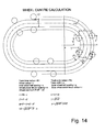
- the optimum positions for the wheels, and the maximum clearance as the carriage traverses the joint between straight and curve can be determined using the formulae accompanying the diagram shown in Figure 14 .
- the maximum clearance would be 0.31mm. In many applications this would be too much. These clearances become even larger if the radius of the curved sections is smaller, and if any of the dimensions of the trapezium formed by the centres of the bearing wheels increase. In practice, the need to limit the clearances has the effect of limiting the track shapes which can be made, and also minimising the separation of the bearing wheels with a consequent limitation of the moment load capacity of the carriages.
- a second type of carriage ( Figure 3 ) has two pairs of bearing wheels, each mounted on a sub-plate which is then connected by a pivot to the main carriage plate.
- These sub-plate assemblies move to allow the carriage to travel around tracks with left handed and right handed curves, and curves of differing radii, with very little clearance between bearing wheels and the track.
- the additional parts and complexity of the sub-plates and swivel bearings makes these carriages more expensive than the first type, and they are not suited to traversing track systems with very tight bend radii.
- the sub-plates and bearings may also result in increased friction between the bearing wheels and the track.
- NL 1 001 452-C discloses a track and carriage system for reading barcodes.
- the carriages have a single bearing wheel on one side of the track and a pair of bearing wheels on an opposite side of the track.
- Tracks and carriages are also used in overhead rail systems where the track forms a rail which varies in a vertical plane, and the wheels run along the upper and lower surfaces of the rail. In such systems the weight of the carriage and any load which it carries always act in a downward direction helping to maintain contact with the rail.
- Japanese Utility Model No. 5-54601 discloses an overhead rail system in which the carriage has bearing wheels which run along the upper surface of the rail and a single guide wheel which contacts a lower surface of the rail. At curved sections the upper surface of the rail is cut away so that the rail becomes thinner, but this would not allow close contact to be simultaneously maintained with the upper and lower surfaces of the rail, particularly if the upper surface lies on the outer radius of a curve ( Fig. 2 ).
- GB 2 261 863-A discloses a conveyor system having powered trolleys mounted on an overhead rail of varying thickness.
- a single drive wheel operates against an upper surface of the rail and a pair of spaced bucking rollers are provided with pressure means (i.e. spring loaded) to ensure adherence of the drive wheel with the rail.
- pressure means i.e. spring loaded
- a major disadvantage of such an arrangement is that the spring loading increases friction between the carriage and the rail.
- variable spring loading is essential to maintain low friction.
- JP 3 070 670-A A similar suspended rail and carriage arrangement is disclosed in JP 3 070 670-A , in which the carriage again has a single drive wheel on an upper surface of the rail and a pair of spring loaded wheels which maintain contact with a lower surface of the rail.
- the radius of curvature of the lower surface is changed by a predetermined amount relative to the radius required for a uniform thickness.
- the present invention seeks to provide a new and inventive form of track system in which the carriages can have a large transverse moment load capacity and relatively free movement with a minimum number of components, and which provides considerably greater flexibility in the layout of the tracks.
- the present invention arises from a new perception that if a carriage is provided with three bearing wheels mounted in fixed positions, one engaging one side of the track and two engaging the other, the profile of the track can be configured in such a way that a very small clearance can be achieved throughout a much broader range of shapes than has hitherto been possible.
- Such track profiles may, for example, encompass extremely complex shapes which comprise inside and outside curves and radii of curvature varying from substantially straight sections to very tight curves.
- the present invention thus provides a track system having a carriage with a single bearing on the inside of an endless track and a pair of bearing wheels on the outside of the track.
- a three-bearing carriage generally has a lower load capacity than an equivalent four-bearing carriage, and the position of the peak load carrying capacity is offset from the geometrical centre of the carriage.
- the single bearing has a larger load capacity (i.e. is of greater diameter) than the two bearing wheels on the opposite side.
- the present invention thus provides a track system having a carriage with a single bearing wheel on one side which is of greater diameter than the two bearing wheels on the opposite side.
- the invention also provides a track system in which the track is manufactured from a single piece of metal without joints.
- the invention further provides a track system in which the track is integrally formed with a base plate. This can eliminate any problems associated with assembly and setting, and possible movement of the joints in use.
- the combined track and integral base plate may also be used as a structural element within a machine.
- the invention also provides a track system in which the track is formed of separate sections. More particularly, in large track systems it may be necessary to manufacture the track in sections, but the individual sections may be of variable curvature resulting in a reduced number of joints.
- the invention also provides a track system in which there is at least one section which includes two or more of a straight portion, an outside curved portion, and an inside curved portion.
- the invention also provides a track system having mutually spaced inner and outer sections and a rack, and each carriage carries a pinion which is mounted between the inner and outer sections in continuous driving engagement with the rack.
- the invention also provides a track system in which the track is located between the bearing wheels of the carriage so that the bearing wheels engage on the outside of the track profile.
- the invention further provides a track system in which the track is in the form of a profiled channel with internal shape features which engage and locate on corresponding features on the carriage bearing wheels.
- the invention also provides a track system in which the maximum clearance between the carriage bearing wheels and the respective sides of the track is less than 0.075mm.
- the invention also provides a track system in which the maximum clearance between the carriage bearing wheels and the respective sides of the track is less than 0.05mm.
- Fig. 1 is a general view of a track system which is representative of the prior art. This version uses a carriage with four bearing wheels located at fixed positions on a carriage, and this runs around a closed track which is substantially triangular in shape.
- Fig. 2 is a general view of a track system which is representative of the prior art. This version uses a carriage with four bearing wheels located at fixed positions on a carriage, and this runs along an open track which is substantially L-shaped.
- Fig. 3 is a general view of a track system which is representative of the prior art. This version uses a carriage with two pairs of bearing wheels each located on sub-plates which are connected by pivots to a carriage plate. This runs around a closed track which has curved portions of differing radii and direction.
- Fig. 14 apply to prior art track systems such as those of Fig.s 1 and 2 in which the carriages have four fixed wheels.
- the formulae allow the optimum positions of the wheels to be determined in a situation where there is zero clearance when all four wheels are either entirely on the straight or entirely on the curve, and also provide a means of calculating the maximum clearance at the transition with any values for the characteristic dimensions r, p & z.
- the maximum clearance is calculated to be 0.31mm.
- the vast majority of useful track systems would have a calculated lift-off within the range 0.1 to 0.5mm, and it would be difficult to find a known track system with a clearance better than 0.075 mm.
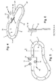
- Fig. 4 is a general view of a track system in accordance with the present invention. This includes straight sections 20, curves of differing radii 21, 22 and both inside and outside curves 23. A carriage 10 with three bearing wheels 12, 13 and 14 is mounted on the track.
- Fig. 5 is a plan view of the track shown in Fig. 4 . This shows that the sectional width of the track varies around the circuit.
- Fig. 6 is a sectional view of the track shown in Fig.s 4 and 5 . This shows the profiles of the bearing wheels 12, 13 and 14 engaged on the corresponding features of the track.
- the track system includes an endless track 1 having an inside edge 4 and an outside edge 5 each provided with a respective rail 6, 7.
- the track 1 is machined without joints from a single piece of material.
- the track is used with a set of carriages 10, one of which is shown.
- the carriages may be interlinked and driven by a suitable drive mechanism (not shown) so that they all travel continuously around the track.
- Each carriage has a carriage plate 11 of any suitable shape, beneath which are mounted suitable bearing wheels 12, 13 and 14.
- the carriage On one side of the track, i.e. the inside edge 4, the carriage has a single bearing 12 to engage the inside rail 6.
- the carriage On the opposite outside edge 5 the carriage has a pair of spaced bearing wheels 13 and 14 to engage the outside rail 7, one of which is arranged to lead the single bearing 12 and the other arranged to follow.
- the dimensions of the track 1 are accurately calculated such that the width of the track between the side edges 4 and 5 varies in such a way that the curvature of both sides changes smoothly without abrupt changes in radius. As the carriage moves around the track, a close tolerance is maintained between the bearing wheels and the sides of the track, eliminating any lateral play.
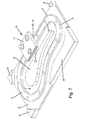
- Fig. 7 is a general view of a track system in accordance with the design. This is similar to the track shown in Fig.s 4 to 6 , but includes a base plate 2 integral with the track 1. This may obviate the need for a separate mounting plate, and can also form a strong, structural element of a machine incorporating the track.
- the track 1 is supported by the base plate 2 but is otherwise similar the track previously described.
- the track 1 and base plate 2 are both machined without joints from a single piece of material.
- the base plate has integral raised areas 8, which are coplanar with the upper surface of the track 1 and spaced from its inside edge 4, but depending on the application the base plate 2 may also be flat.
- the track is used with a set of carriages 10, one of which is shown.
- the carriages may be interlinked and driven by a suitable drive mechanism (not shown) so that they all travel continuously around the track.
- Each carriage has a carriage plate 11 of any suitable shape, beneath which are mounted suitable bearing wheels 12, 13 and 14.
- the carriage On one side of the track, i.e. the inside edge 4, the carriage has a single bearing 12 to engage the inside rail 6.
- the carriage On the opposite outside edge 5 the carriage has a pair of spaced bearing wheels 13 and 14 to engage the outside rail 7, one of which is arranged to lead the single bearing 12 and the other arranged to follow.
- the dimensions of the track 1 are accurately calculated such that the width of the track between the side edges 4 and 5 varies in such a way that, as the carriage moves around the track, a close tolerance is maintained between the bearing wheels and the sides of the track.
- Fig. 8 is a general view of another track system in accordance with the invention.
- An inherent disadvantage of a three-bearing carriage is that it has a lower load capacity compared with a four-bearing carriage, and the position of the load carrying capacity does not lie at the geometrical centre of the carriage.
- the single bearing 12 is increased in diameter by an appropriate amount relative to the other two bearing wheels 13 and 14, so that it is possible to centre the load capacity and increase it to that of an equivalent four-bearing carriage.
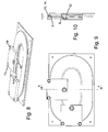
- Fig. 9 is a plan view of the track shown in Fig. 8 . This shows that the sectional width of the track 1 varies around the circuit.
- Fig. 10 is a sectional view of the track shown in Fig.s 8 and 9 . This shows the asymmetry of the bearing wheels 12, 13 and 14 and track edge profiles 6 and 7.
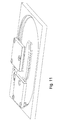
- Fig. 11 is a general view of a further track system in accordance with the invention.
- the carriage design and path is similar to the track shown in Fig.s 8-10 but the track is configured as a channel such that the bearing wheels engage on the inside of the channel. This has advantages, particularly offering a much higher transverse moment load capacity than the alternative configuration.
- FIG. 12 A further embodiment of the track system of the invention is shown in Fig. 12 .
- This track system includes an endless track 1 which comprises inner and outer sections 101 and 102 supported by a base plate 2.
- the inside edge of the inner section 101 is provided with an inner rail 106
- the outside edge of the outer section 102 is similarly provided with an outer rail 107, both spaced above the base plate 2.
- Each carriage 10 has a carriage plate 11, beneath which are mounted suitable bearing wheels 12, 13 and 14.
- the single bearing 12 is larger than the other two bearing wheels 13 and 14 and is arranged to engage the rail 106 on the inside of the track.
- Bearing wheels 13 and 14 engage the outside rail 107, one being arranged to lead the single bearing 12 and the other arranged to follow.
- the carriage plate 11 carries a rotatable pinion 110 which is located in the space between the inner and outer track sections 101 and 102.
- the pinion is engaged with a rack 111, which in this example is formed on the outside edge of the inner section 101.
- the dimensions of the track sections 101 and 102 are accurately calculated such that the width of the track between the rails 106 and 107 varies in such a way that, as the carriage moves around the track, a close tolerance is maintained between the bearing wheels and the sides of the track.
- the pitch line of the rack and gear follows the curve of the track in such a way that there is a uniform small clearance between the pinion 110 and the rack 111.
- FIG. 13 Another embodiment of a rack and pinion track system of the invention, showing a more complex track shape comprised of inside and outside curves of continuously changing radius, is shown in Fig. 13 .
- This track system includes an endless track 1 which comprises inner and outer sections 101 and 102 supported by a base plate 2.
- the inside edge of the inner section 101 is provided with an inner rail 106
- the outside edge of the outer section 102 is similarly provided with an outer rail 107, both spaced above the base plate 2.
- Each carriage 10 has a carriage plate 11, beneath which are mounted suitable bearing wheels 12, 13 and 14.
- the single bearing 12 is larger than the other two bearing wheels 13 and 14 and is arranged to engage the rail 106 on the inside of the track.
- Bearing wheels 13 and 14 engage the outside rail 107, one being arranged to lead the single bearing 12 and the other arranged to follow. Between the three bearing wheels the carriage plate 11 carries a rotatable pinion 110 which is located in the space between the inner and outer track sections 101 and 102. The pinion is engaged with a rack 121, which in this example is formed on the inside edge of the outer section 102. As in the previous examples, the dimensions of the track sections 101 and 102 are accurately calculated such that the width of the track between the rails 106 and 107 varies in such a way that, as the carriage moves around the track, a close tolerance is maintained between the bearing wheels and the sides of the track.
- the pitch line of the rack 121 and pinion 110 follows the curve of the track in such a way that there is a uniform small clearance between the pinion and the rack.
- the pinion can be used to provide rotary drive take-off to the carriages.
- the carriages could be provided with a motor to drive the pinion and thereby move the carriages around the track.
Landscapes
- Engineering & Computer Science (AREA)
- Mechanical Engineering (AREA)
- Transportation (AREA)
- Bearings For Parts Moving Linearly (AREA)
- Transmission Devices (AREA)
Applications Claiming Priority (1)
| Application Number | Priority Date | Filing Date | Title |
|---|---|---|---|
| GBGB1200888.4A GB201200888D0 (en) | 2012-01-19 | 2012-01-19 | Track systems |
Publications (3)
| Publication Number | Publication Date |
|---|---|
| EP2617620A2 true EP2617620A2 (fr) | 2013-07-24 |
| EP2617620A3 EP2617620A3 (fr) | 2013-09-18 |
| EP2617620B1 EP2617620B1 (fr) | 2020-07-08 |
Family
ID=45814229
Family Applications (1)
| Application Number | Title | Priority Date | Filing Date |
|---|---|---|---|
| EP13000177.9A Active EP2617620B1 (fr) | 2012-01-19 | 2013-01-14 | Systèmes de piste |
Country Status (3)
| Country | Link |
|---|---|
| US (1) | US8833263B2 (fr) |
| EP (1) | EP2617620B1 (fr) |
| GB (2) | GB201200888D0 (fr) |
Cited By (5)
| Publication number | Priority date | Publication date | Assignee | Title |
|---|---|---|---|---|
| EP3038959B1 (fr) | 2013-08-26 | 2017-11-22 | Robert Bosch GmbH | Dispositif transporteur |
| CN108867206A (zh) * | 2018-07-04 | 2018-11-23 | 深圳星河智能科技有限公司 | 一种轨道的设计方法及该轨道 |
| CN109926769A (zh) * | 2019-03-01 | 2019-06-25 | 中民筑友有限公司 | 一种用于钢筋笼焊接的箍筋自动输送装置 |
| IT202000015373A1 (it) | 2020-06-25 | 2021-12-25 | Sonzogni Camme S P A | Sistema di movimentazione materiali mediante binario e carrelli |
| IT202200006647A1 (it) * | 2022-04-04 | 2023-10-04 | Nadella S P A | Sistema comprendente una pista ed un carrello sterzante. |
Families Citing this family (16)
| Publication number | Priority date | Publication date | Assignee | Title |
|---|---|---|---|---|
| GB201200888D0 (en) * | 2012-01-19 | 2012-02-29 | Hepco Slide Systems Ltd | Track systems |
| SE1451590A1 (sv) * | 2014-12-18 | 2016-04-26 | Il Granito Ab | Track, load carrying carriage and track system |
| KR101706985B1 (ko) * | 2015-03-12 | 2017-02-16 | 주식회사 세진아이지비 | 동력전달장치 |
| USD788929S1 (en) * | 2015-10-21 | 2017-06-06 | Rehabilitation Institute Of Chicago | Gait track |
| USD788930S1 (en) * | 2015-10-21 | 2017-06-06 | Rehabilitation Institute Of Chicago | Gait track |
| US10239418B2 (en) | 2016-06-21 | 2019-03-26 | Rockwell Automation Technologies, Inc. | Multi-trajectory track and mover system |
| IT201600097555A1 (it) * | 2016-09-29 | 2018-03-29 | Marchesini Group Spa | Sistema di trasporto per il trasporto di prodotti |
| KR101904117B1 (ko) | 2017-03-14 | 2018-10-04 | 주식회사 세진아이지비 | 가이드 모듈 및 그를 구비하는 구동장치 |
| US11146047B2 (en) * | 2017-06-27 | 2021-10-12 | Janet Stephens | Cable pulling apparatus for cable tray |
| CN107539820A (zh) * | 2017-09-19 | 2018-01-05 | 广西科技大学鹿山学院 | 考卷自动装订机 |
| CN108502476B (zh) * | 2018-05-04 | 2023-06-16 | 浙江衣拿智能科技股份有限公司 | 制衣吊挂系统快速投放装置 |
| CN111361944B (zh) * | 2020-04-07 | 2025-02-25 | 颖态智能技术(上海)有限公司 | 用于任意连续曲线导轨传输的滑动装置 |
| DE112021005863B4 (de) | 2021-06-17 | 2026-03-19 | Mitsubishi Electric Corporation | Lineartransportvorrichtung |
| EP4190725A1 (fr) * | 2021-12-02 | 2023-06-07 | Primetals Technologies Austria GmbH | Dispositif de transport et procédé de transport des faisceaux de bandes métalliques |
| KR102777378B1 (ko) * | 2022-03-02 | 2025-03-07 | (주)아이지비 | 가이드 모듈을 구비하는 구동장치 |
| CN116461909A (zh) * | 2023-05-26 | 2023-07-21 | 安徽巨一科技股份有限公司 | 一种具备积放功能的立体环形输送线 |
Family Cites Families (29)
| Publication number | Priority date | Publication date | Assignee | Title |
|---|---|---|---|---|
| US3774548A (en) * | 1971-01-13 | 1973-11-27 | A Borst | Gripping locomotive for suspended railway |
| JPS55109820A (en) * | 1979-02-14 | 1980-08-23 | Hiroshi Teramachi | Linear ball bearing unit for floating load |
| DE3403460A1 (de) * | 1984-02-01 | 1985-08-08 | Georg 8200 Rosenheim Uttscheid | Elektrohaengebahn |
| DE68920795T2 (de) * | 1988-08-10 | 1995-05-18 | Yamaha Motor Co Ltd | Transportvorrichtung. |
| JPH037060A (ja) | 1989-06-01 | 1991-01-14 | Fuji Electric Co Ltd | 可変過電流保護dc―dcコンバータ |
| JP2876559B2 (ja) * | 1989-08-09 | 1999-03-31 | ヤマハ発動機株式会社 | 軌道装置 |
| JP2866974B2 (ja) * | 1990-03-26 | 1999-03-08 | 日本トムソン株式会社 | 直動転がり案内ユニット |
| JP2964727B2 (ja) | 1991-08-28 | 1999-10-18 | 株式会社富士通ゼネラル | 静止画と音声の再生装置 |
| GB2261863B (en) * | 1991-11-29 | 1995-02-22 | Fata Automation | Material conveyor system comprising powered trolleys on an overhead rail |
| JP2590546Y2 (ja) * | 1991-12-18 | 1999-02-17 | 豊国工業株式会社 | 懸垂台車のレール構造 |
| BE1006167A3 (fr) * | 1992-01-02 | 1994-05-31 | Fata Automation | Ensemble transporteur a rail suspendu. |
| JPH0650333A (ja) * | 1992-07-30 | 1994-02-22 | Nippon Seiko Kk | リニアガイド装置 |
| JP3242487B2 (ja) * | 1993-04-23 | 2001-12-25 | 日本トムソン株式会社 | 転がり案内ユニット |
| NL1001452C2 (nl) * | 1995-10-20 | 1997-04-22 | Jan Theodorus Kusters | Railsysteem voor een magazijnrobot. |
| JP3481771B2 (ja) * | 1996-04-25 | 2003-12-22 | Thk株式会社 | 直線案内装置のスライダの製造方法 |
| US5735214A (en) * | 1996-12-27 | 1998-04-07 | Tsuboi; Nobuyuki | Streamline track system with carriers and rail |
| KR100702377B1 (ko) * | 1999-06-09 | 2007-04-02 | 티에치케이 가부시끼가이샤 | 자재안내장치 및 이것을 사용한 테이블 이송장치 |
| US7182024B2 (en) * | 2005-03-16 | 2007-02-27 | Seagate Technology Llc | Flexible rail section |
| WO2007055208A1 (fr) * | 2005-11-08 | 2007-05-18 | Thk Co., Ltd. | Dispositif de guidage de mouvement, systeme de mouvement relatif, et mecanisme d’absorption de deplacement |
| DE102006012623A1 (de) * | 2006-03-20 | 2007-09-27 | Schaeffler Kg | Wälzkörperkette |
| WO2008123371A1 (fr) * | 2007-03-29 | 2008-10-16 | Thk Co., Ltd. | Dispositif de guidage de mouvement et son procédé de production |
| WO2009034923A1 (fr) * | 2007-09-14 | 2009-03-19 | Thk Co., Ltd. | Rail de voie et dispositif de guidage de mouvement doté du rail de voie |
| US7850146B2 (en) * | 2008-06-13 | 2010-12-14 | Production Resource Group, Llc | Lineset winch with braking parts |
| US8328422B2 (en) * | 2009-01-19 | 2012-12-11 | Hiwin Technologies Corp. | Component for linear guideway and method for making the same |
| DE102009009006A1 (de) * | 2009-02-16 | 2010-08-19 | Robert Bosch Gmbh | Linearbewegungsvorrichtung mit einer Umlenkbaugruppe mit einem einzigen Umlenkdurchgang |
| DE102009009012A1 (de) * | 2009-02-16 | 2010-08-19 | Robert Bosch Gmbh | Linearbewegungsvorrichtung mit absatzfreiem Rücklaufdurchgang |
| JPWO2010137108A1 (ja) * | 2009-05-25 | 2012-11-12 | 株式会社S&Sエンジニアリング | 台車を水平姿勢に保持する搬送システム |
| US8220997B2 (en) * | 2009-08-04 | 2012-07-17 | Hiwin Technologies Corp. | Circulating system for a linear guideway |
| GB201200888D0 (en) * | 2012-01-19 | 2012-02-29 | Hepco Slide Systems Ltd | Track systems |
-
2012
- 2012-01-19 GB GBGB1200888.4A patent/GB201200888D0/en not_active Ceased
-
2013
- 2013-01-10 GB GB1300443.7A patent/GB2499881B/en not_active Expired - Fee Related
- 2013-01-14 EP EP13000177.9A patent/EP2617620B1/fr active Active
- 2013-01-18 US US13/694,916 patent/US8833263B2/en active Active
Cited By (7)
| Publication number | Priority date | Publication date | Assignee | Title |
|---|---|---|---|---|
| EP3038959B1 (fr) | 2013-08-26 | 2017-11-22 | Robert Bosch GmbH | Dispositif transporteur |
| CN108867206A (zh) * | 2018-07-04 | 2018-11-23 | 深圳星河智能科技有限公司 | 一种轨道的设计方法及该轨道 |
| CN109926769A (zh) * | 2019-03-01 | 2019-06-25 | 中民筑友有限公司 | 一种用于钢筋笼焊接的箍筋自动输送装置 |
| IT202000015373A1 (it) | 2020-06-25 | 2021-12-25 | Sonzogni Camme S P A | Sistema di movimentazione materiali mediante binario e carrelli |
| EP3929113A1 (fr) | 2020-06-25 | 2021-12-29 | Sonzogni Camme S.P.A. | Système de manutention de matériaux au moyen d'un guide et de chariots |
| IT202200006647A1 (it) * | 2022-04-04 | 2023-10-04 | Nadella S P A | Sistema comprendente una pista ed un carrello sterzante. |
| WO2023194879A1 (fr) * | 2022-04-04 | 2023-10-12 | Nadella S.P.A. | Système comprenant un rail et un chariot de direction |
Also Published As
| Publication number | Publication date |
|---|---|
| GB201200888D0 (en) | 2012-02-29 |
| US20130192487A1 (en) | 2013-08-01 |
| EP2617620B1 (fr) | 2020-07-08 |
| GB2499881B (en) | 2017-06-07 |
| GB2499881A (en) | 2013-09-04 |
| EP2617620A3 (fr) | 2013-09-18 |
| GB201300443D0 (en) | 2013-02-27 |
| US8833263B2 (en) | 2014-09-16 |
Similar Documents
| Publication | Publication Date | Title |
|---|---|---|
| EP2617620B1 (fr) | Systèmes de piste | |
| CN110506019B (zh) | 提供减小的加工间距的线性马达输送系统及其移动元件 | |
| KR100792612B1 (ko) | 유궤도대차 시스템 | |
| US4595244A (en) | Recirculating-ball linear bearing | |
| US4692039A (en) | Recirculating-ball linear bearing and guide rail therefor | |
| US4862807A (en) | Passive railway switching system | |
| US9458883B2 (en) | Motion-guiding device | |
| CN203308911U (zh) | 滚轮轴承的滑块导轨装置 | |
| CN205972675U (zh) | 一种循环运输装置 | |
| JP2011043192A (ja) | ガイド装置 | |
| CN222023390U (zh) | 一种换向调节装置 | |
| CN203362825U (zh) | 一种高速精密滚柱直线导轨副 | |
| CN211225146U (zh) | 一种压轮调节装置 | |
| CN220470480U (zh) | 一种摩擦阻力小的t形导轨 | |
| CN103273249A (zh) | 具有十字滑台的汽车焊装生产设备 | |
| CN109706797B (zh) | 一种低等效锥度的直基本轨及道岔转辙器 | |
| CN208728392U (zh) | 硬骨架伺服四轴成型设备 | |
| WO2016099387A1 (fr) | Rail, chariot porteur et système à rail | |
| CN109789975B (zh) | 用于运输产品的运输系统 | |
| CN209412067U (zh) | 一种优化的吊挂冷却器的行走机构 | |
| CN219975137U (zh) | 圆弧曲面轨道 | |
| CN218702511U (zh) | 一种滚轮 | |
| CN102837942A (zh) | 引导载件在直曲复合轨道上移动的导引构造 | |
| GB2459132A (en) | Sliding support assembly | |
| CN113059365B (zh) | 一种侧挂式机床磁悬浮导轨 |
Legal Events
| Date | Code | Title | Description |
|---|---|---|---|
| PUAI | Public reference made under article 153(3) epc to a published international application that has entered the european phase |
Free format text: ORIGINAL CODE: 0009012 |
|
| AK | Designated contracting states |
Kind code of ref document: A2 Designated state(s): AL AT BE BG CH CY CZ DE DK EE ES FI FR GB GR HR HU IE IS IT LI LT LU LV MC MK MT NL NO PL PT RO RS SE SI SK SM TR |
|
| AX | Request for extension of the european patent |
Extension state: BA ME |
|
| PUAL | Search report despatched |
Free format text: ORIGINAL CODE: 0009013 |
|
| RIC1 | Information provided on ipc code assigned before grant |
Ipc: B61B 13/02 20060101AFI20130808BHEP Ipc: B61B 13/04 20060101ALI20130808BHEP |
|
| AK | Designated contracting states |
Kind code of ref document: A3 Designated state(s): AL AT BE BG CH CY CZ DE DK EE ES FI FR GB GR HR HU IE IS IT LI LT LU LV MC MK MT NL NO PL PT RO RS SE SI SK SM TR |
|
| AX | Request for extension of the european patent |
Extension state: BA ME |
|
| RIC1 | Information provided on ipc code assigned before grant |
Ipc: B61B 13/02 20060101AFI20130809BHEP Ipc: B61B 13/04 20060101ALI20130809BHEP |
|
| 17P | Request for examination filed |
Effective date: 20140213 |
|
| RBV | Designated contracting states (corrected) |
Designated state(s): AL AT BE BG CH CY CZ DE DK EE ES FI FR GB GR HR HU IE IS IT LI LT LU LV MC MK MT NL NO PL PT RO RS SE SI SK SM TR |
|
| 17Q | First examination report despatched |
Effective date: 20151001 |
|
| STAA | Information on the status of an ep patent application or granted ep patent |
Free format text: STATUS: EXAMINATION IS IN PROGRESS |
|
| GRAP | Despatch of communication of intention to grant a patent |
Free format text: ORIGINAL CODE: EPIDOSNIGR1 |
|
| STAA | Information on the status of an ep patent application or granted ep patent |
Free format text: STATUS: GRANT OF PATENT IS INTENDED |
|
| INTG | Intention to grant announced |
Effective date: 20191114 |
|
| GRAS | Grant fee paid |
Free format text: ORIGINAL CODE: EPIDOSNIGR3 |
|
| GRAJ | Information related to disapproval of communication of intention to grant by the applicant or resumption of examination proceedings by the epo deleted |
Free format text: ORIGINAL CODE: EPIDOSDIGR1 |
|
| GRAL | Information related to payment of fee for publishing/printing deleted |
Free format text: ORIGINAL CODE: EPIDOSDIGR3 |
|
| STAA | Information on the status of an ep patent application or granted ep patent |
Free format text: STATUS: EXAMINATION IS IN PROGRESS |
|
| INTC | Intention to grant announced (deleted) | ||
| GRAP | Despatch of communication of intention to grant a patent |
Free format text: ORIGINAL CODE: EPIDOSNIGR1 |
|
| STAA | Information on the status of an ep patent application or granted ep patent |
Free format text: STATUS: GRANT OF PATENT IS INTENDED |
|
| INTG | Intention to grant announced |
Effective date: 20200407 |
|
| GRAS | Grant fee paid |
Free format text: ORIGINAL CODE: EPIDOSNIGR3 |
|
| GRAA | (expected) grant |
Free format text: ORIGINAL CODE: 0009210 |
|
| STAA | Information on the status of an ep patent application or granted ep patent |
Free format text: STATUS: THE PATENT HAS BEEN GRANTED |
|
| AK | Designated contracting states |
Kind code of ref document: B1 Designated state(s): AL AT BE BG CH CY CZ DE DK EE ES FI FR GB GR HR HU IE IS IT LI LT LU LV MC MK MT NL NO PL PT RO RS SE SI SK SM TR |
|
| REG | Reference to a national code |
Ref country code: GB Ref legal event code: FG4D |
|
| REG | Reference to a national code |
Ref country code: AT Ref legal event code: REF Ref document number: 1288137 Country of ref document: AT Kind code of ref document: T Effective date: 20200715 Ref country code: CH Ref legal event code: EP |
|
| REG | Reference to a national code |
Ref country code: DE Ref legal event code: R096 Ref document number: 602013070440 Country of ref document: DE |
|
| REG | Reference to a national code |
Ref country code: IE Ref legal event code: FG4D |
|
| REG | Reference to a national code |
Ref country code: LT Ref legal event code: MG4D |
|
| REG | Reference to a national code |
Ref country code: AT Ref legal event code: MK05 Ref document number: 1288137 Country of ref document: AT Kind code of ref document: T Effective date: 20200708 |
|
| REG | Reference to a national code |
Ref country code: NL Ref legal event code: MP Effective date: 20200708 |
|
| PG25 | Lapsed in a contracting state [announced via postgrant information from national office to epo] |
Ref country code: FI Free format text: LAPSE BECAUSE OF FAILURE TO SUBMIT A TRANSLATION OF THE DESCRIPTION OR TO PAY THE FEE WITHIN THE PRESCRIBED TIME-LIMIT Effective date: 20200708 Ref country code: GR Free format text: LAPSE BECAUSE OF FAILURE TO SUBMIT A TRANSLATION OF THE DESCRIPTION OR TO PAY THE FEE WITHIN THE PRESCRIBED TIME-LIMIT Effective date: 20201009 Ref country code: SE Free format text: LAPSE BECAUSE OF FAILURE TO SUBMIT A TRANSLATION OF THE DESCRIPTION OR TO PAY THE FEE WITHIN THE PRESCRIBED TIME-LIMIT Effective date: 20200708 Ref country code: NO Free format text: LAPSE BECAUSE OF FAILURE TO SUBMIT A TRANSLATION OF THE DESCRIPTION OR TO PAY THE FEE WITHIN THE PRESCRIBED TIME-LIMIT Effective date: 20201008 Ref country code: HR Free format text: LAPSE BECAUSE OF FAILURE TO SUBMIT A TRANSLATION OF THE DESCRIPTION OR TO PAY THE FEE WITHIN THE PRESCRIBED TIME-LIMIT Effective date: 20200708 Ref country code: AT Free format text: LAPSE BECAUSE OF FAILURE TO SUBMIT A TRANSLATION OF THE DESCRIPTION OR TO PAY THE FEE WITHIN THE PRESCRIBED TIME-LIMIT Effective date: 20200708 Ref country code: LT Free format text: LAPSE BECAUSE OF FAILURE TO SUBMIT A TRANSLATION OF THE DESCRIPTION OR TO PAY THE FEE WITHIN THE PRESCRIBED TIME-LIMIT Effective date: 20200708 Ref country code: PT Free format text: LAPSE BECAUSE OF FAILURE TO SUBMIT A TRANSLATION OF THE DESCRIPTION OR TO PAY THE FEE WITHIN THE PRESCRIBED TIME-LIMIT Effective date: 20201109 Ref country code: BG Free format text: LAPSE BECAUSE OF FAILURE TO SUBMIT A TRANSLATION OF THE DESCRIPTION OR TO PAY THE FEE WITHIN THE PRESCRIBED TIME-LIMIT Effective date: 20201008 Ref country code: ES Free format text: LAPSE BECAUSE OF FAILURE TO SUBMIT A TRANSLATION OF THE DESCRIPTION OR TO PAY THE FEE WITHIN THE PRESCRIBED TIME-LIMIT Effective date: 20200708 |
|
| PG25 | Lapsed in a contracting state [announced via postgrant information from national office to epo] |
Ref country code: IS Free format text: LAPSE BECAUSE OF FAILURE TO SUBMIT A TRANSLATION OF THE DESCRIPTION OR TO PAY THE FEE WITHIN THE PRESCRIBED TIME-LIMIT Effective date: 20201108 Ref country code: LV Free format text: LAPSE BECAUSE OF FAILURE TO SUBMIT A TRANSLATION OF THE DESCRIPTION OR TO PAY THE FEE WITHIN THE PRESCRIBED TIME-LIMIT Effective date: 20200708 Ref country code: PL Free format text: LAPSE BECAUSE OF FAILURE TO SUBMIT A TRANSLATION OF THE DESCRIPTION OR TO PAY THE FEE WITHIN THE PRESCRIBED TIME-LIMIT Effective date: 20200708 Ref country code: RS Free format text: LAPSE BECAUSE OF FAILURE TO SUBMIT A TRANSLATION OF THE DESCRIPTION OR TO PAY THE FEE WITHIN THE PRESCRIBED TIME-LIMIT Effective date: 20200708 |
|
| PG25 | Lapsed in a contracting state [announced via postgrant information from national office to epo] |
Ref country code: NL Free format text: LAPSE BECAUSE OF FAILURE TO SUBMIT A TRANSLATION OF THE DESCRIPTION OR TO PAY THE FEE WITHIN THE PRESCRIBED TIME-LIMIT Effective date: 20200708 |
|
| REG | Reference to a national code |
Ref country code: DE Ref legal event code: R097 Ref document number: 602013070440 Country of ref document: DE |
|
| PG25 | Lapsed in a contracting state [announced via postgrant information from national office to epo] |
Ref country code: SM Free format text: LAPSE BECAUSE OF FAILURE TO SUBMIT A TRANSLATION OF THE DESCRIPTION OR TO PAY THE FEE WITHIN THE PRESCRIBED TIME-LIMIT Effective date: 20200708 Ref country code: RO Free format text: LAPSE BECAUSE OF FAILURE TO SUBMIT A TRANSLATION OF THE DESCRIPTION OR TO PAY THE FEE WITHIN THE PRESCRIBED TIME-LIMIT Effective date: 20200708 Ref country code: CZ Free format text: LAPSE BECAUSE OF FAILURE TO SUBMIT A TRANSLATION OF THE DESCRIPTION OR TO PAY THE FEE WITHIN THE PRESCRIBED TIME-LIMIT Effective date: 20200708 Ref country code: DK Free format text: LAPSE BECAUSE OF FAILURE TO SUBMIT A TRANSLATION OF THE DESCRIPTION OR TO PAY THE FEE WITHIN THE PRESCRIBED TIME-LIMIT Effective date: 20200708 Ref country code: EE Free format text: LAPSE BECAUSE OF FAILURE TO SUBMIT A TRANSLATION OF THE DESCRIPTION OR TO PAY THE FEE WITHIN THE PRESCRIBED TIME-LIMIT Effective date: 20200708 |
|
| PLBE | No opposition filed within time limit |
Free format text: ORIGINAL CODE: 0009261 |
|
| STAA | Information on the status of an ep patent application or granted ep patent |
Free format text: STATUS: NO OPPOSITION FILED WITHIN TIME LIMIT |
|
| PG25 | Lapsed in a contracting state [announced via postgrant information from national office to epo] |
Ref country code: AL Free format text: LAPSE BECAUSE OF FAILURE TO SUBMIT A TRANSLATION OF THE DESCRIPTION OR TO PAY THE FEE WITHIN THE PRESCRIBED TIME-LIMIT Effective date: 20200708 |
|
| 26N | No opposition filed |
Effective date: 20210409 |
|
| PG25 | Lapsed in a contracting state [announced via postgrant information from national office to epo] |
Ref country code: SK Free format text: LAPSE BECAUSE OF FAILURE TO SUBMIT A TRANSLATION OF THE DESCRIPTION OR TO PAY THE FEE WITHIN THE PRESCRIBED TIME-LIMIT Effective date: 20200708 |
|
| PG25 | Lapsed in a contracting state [announced via postgrant information from national office to epo] |
Ref country code: MC Free format text: LAPSE BECAUSE OF FAILURE TO SUBMIT A TRANSLATION OF THE DESCRIPTION OR TO PAY THE FEE WITHIN THE PRESCRIBED TIME-LIMIT Effective date: 20200708 Ref country code: SI Free format text: LAPSE BECAUSE OF FAILURE TO SUBMIT A TRANSLATION OF THE DESCRIPTION OR TO PAY THE FEE WITHIN THE PRESCRIBED TIME-LIMIT Effective date: 20200708 |
|
| REG | Reference to a national code |
Ref country code: CH Ref legal event code: PL |
|
| PG25 | Lapsed in a contracting state [announced via postgrant information from national office to epo] |
Ref country code: LU Free format text: LAPSE BECAUSE OF NON-PAYMENT OF DUE FEES Effective date: 20210114 |
|
| REG | Reference to a national code |
Ref country code: BE Ref legal event code: MM Effective date: 20210131 |
|
| PG25 | Lapsed in a contracting state [announced via postgrant information from national office to epo] |
Ref country code: LI Free format text: LAPSE BECAUSE OF NON-PAYMENT OF DUE FEES Effective date: 20210131 Ref country code: CH Free format text: LAPSE BECAUSE OF NON-PAYMENT OF DUE FEES Effective date: 20210131 |
|
| PG25 | Lapsed in a contracting state [announced via postgrant information from national office to epo] |
Ref country code: IE Free format text: LAPSE BECAUSE OF NON-PAYMENT OF DUE FEES Effective date: 20210114 |
|
| PG25 | Lapsed in a contracting state [announced via postgrant information from national office to epo] |
Ref country code: BE Free format text: LAPSE BECAUSE OF NON-PAYMENT OF DUE FEES Effective date: 20210131 |
|
| PG25 | Lapsed in a contracting state [announced via postgrant information from national office to epo] |
Ref country code: HU Free format text: LAPSE BECAUSE OF FAILURE TO SUBMIT A TRANSLATION OF THE DESCRIPTION OR TO PAY THE FEE WITHIN THE PRESCRIBED TIME-LIMIT; INVALID AB INITIO Effective date: 20130114 |
|
| PG25 | Lapsed in a contracting state [announced via postgrant information from national office to epo] |
Ref country code: CY Free format text: LAPSE BECAUSE OF FAILURE TO SUBMIT A TRANSLATION OF THE DESCRIPTION OR TO PAY THE FEE WITHIN THE PRESCRIBED TIME-LIMIT Effective date: 20200708 |
|
| PG25 | Lapsed in a contracting state [announced via postgrant information from national office to epo] |
Ref country code: MK Free format text: LAPSE BECAUSE OF FAILURE TO SUBMIT A TRANSLATION OF THE DESCRIPTION OR TO PAY THE FEE WITHIN THE PRESCRIBED TIME-LIMIT Effective date: 20200708 |
|
| PG25 | Lapsed in a contracting state [announced via postgrant information from national office to epo] |
Ref country code: TR Free format text: LAPSE BECAUSE OF FAILURE TO SUBMIT A TRANSLATION OF THE DESCRIPTION OR TO PAY THE FEE WITHIN THE PRESCRIBED TIME-LIMIT Effective date: 20200708 |
|
| PG25 | Lapsed in a contracting state [announced via postgrant information from national office to epo] |
Ref country code: MT Free format text: LAPSE BECAUSE OF FAILURE TO SUBMIT A TRANSLATION OF THE DESCRIPTION OR TO PAY THE FEE WITHIN THE PRESCRIBED TIME-LIMIT Effective date: 20200708 |
|
| PGFP | Annual fee paid to national office [announced via postgrant information from national office to epo] |
Ref country code: GB Payment date: 20260226 Year of fee payment: 14 |
|
| PGFP | Annual fee paid to national office [announced via postgrant information from national office to epo] |
Ref country code: DE Payment date: 20260127 Year of fee payment: 14 |
|
| PGFP | Annual fee paid to national office [announced via postgrant information from national office to epo] |
Ref country code: IT Payment date: 20260123 Year of fee payment: 14 |
|
| PGFP | Annual fee paid to national office [announced via postgrant information from national office to epo] |
Ref country code: FR Payment date: 20260126 Year of fee payment: 14 |