EP2617983A1 - Unité de commande d'entraînement, système de commande d'entraînement et procédé de commande d'entraînement - Google Patents
Unité de commande d'entraînement, système de commande d'entraînement et procédé de commande d'entraînement Download PDFInfo
- Publication number
- EP2617983A1 EP2617983A1 EP11825184.2A EP11825184A EP2617983A1 EP 2617983 A1 EP2617983 A1 EP 2617983A1 EP 11825184 A EP11825184 A EP 11825184A EP 2617983 A1 EP2617983 A1 EP 2617983A1
- Authority
- EP
- European Patent Office
- Prior art keywords
- engine
- motor
- revolutions
- case
- section
- Prior art date
- Legal status (The legal status is an assumption and is not a legal conclusion. Google has not performed a legal analysis and makes no representation as to the accuracy of the status listed.)
- Granted
Links
Images

Classifications
-
- F—MECHANICAL ENGINEERING; LIGHTING; HEATING; WEAPONS; BLASTING
- F02—COMBUSTION ENGINES; HOT-GAS OR COMBUSTION-PRODUCT ENGINE PLANTS
- F02D—CONTROLLING COMBUSTION ENGINES
- F02D28/00—Program control of engines
-
- F—MECHANICAL ENGINEERING; LIGHTING; HEATING; WEAPONS; BLASTING
- F02—COMBUSTION ENGINES; HOT-GAS OR COMBUSTION-PRODUCT ENGINE PLANTS
- F02D—CONTROLLING COMBUSTION ENGINES
- F02D41/00—Electrical control of supply of combustible mixture or its constituents
- F02D41/02—Circuit arrangements for generating control signals
- F02D41/04—Introducing corrections for particular operating conditions
- F02D41/042—Introducing corrections for particular operating conditions for stopping the engine
-
- F—MECHANICAL ENGINEERING; LIGHTING; HEATING; WEAPONS; BLASTING
- F02—COMBUSTION ENGINES; HOT-GAS OR COMBUSTION-PRODUCT ENGINE PLANTS
- F02D—CONTROLLING COMBUSTION ENGINES
- F02D41/00—Electrical control of supply of combustible mixture or its constituents
- F02D41/02—Circuit arrangements for generating control signals
- F02D41/04—Introducing corrections for particular operating conditions
- F02D41/06—Introducing corrections for particular operating conditions for engine starting or warming up
- F02D41/062—Introducing corrections for particular operating conditions for engine starting or warming up for starting
- F02D41/065—Introducing corrections for particular operating conditions for engine starting or warming up for starting at hot start or restart
-
- F—MECHANICAL ENGINEERING; LIGHTING; HEATING; WEAPONS; BLASTING
- F02—COMBUSTION ENGINES; HOT-GAS OR COMBUSTION-PRODUCT ENGINE PLANTS
- F02N—STARTING OF COMBUSTION ENGINES; STARTING AIDS FOR SUCH ENGINES, NOT OTHERWISE PROVIDED FOR
- F02N11/00—Starting of engines by means of electric motors
- F02N11/04—Starting of engines by means of electric motors the motors being associated with current generators
-
- F—MECHANICAL ENGINEERING; LIGHTING; HEATING; WEAPONS; BLASTING
- F02—COMBUSTION ENGINES; HOT-GAS OR COMBUSTION-PRODUCT ENGINE PLANTS
- F02N—STARTING OF COMBUSTION ENGINES; STARTING AIDS FOR SUCH ENGINES, NOT OTHERWISE PROVIDED FOR
- F02N11/00—Starting of engines by means of electric motors
- F02N11/08—Circuits specially adapted for starting of engines
-
- F—MECHANICAL ENGINEERING; LIGHTING; HEATING; WEAPONS; BLASTING
- F02—COMBUSTION ENGINES; HOT-GAS OR COMBUSTION-PRODUCT ENGINE PLANTS
- F02N—STARTING OF COMBUSTION ENGINES; STARTING AIDS FOR SUCH ENGINES, NOT OTHERWISE PROVIDED FOR
- F02N19/00—Starting aids for combustion engines, not otherwise provided for
- F02N19/005—Aiding engine start by starting from a predetermined position, e.g. pre-positioning or reverse rotation
-
- F—MECHANICAL ENGINEERING; LIGHTING; HEATING; WEAPONS; BLASTING
- F02—COMBUSTION ENGINES; HOT-GAS OR COMBUSTION-PRODUCT ENGINE PLANTS
- F02D—CONTROLLING COMBUSTION ENGINES
- F02D41/00—Electrical control of supply of combustible mixture or its constituents
- F02D41/009—Electrical control of supply of combustible mixture or its constituents using means for generating position or synchronisation signals
- F02D2041/0095—Synchronisation of the cylinders during engine shutdown
-
- F—MECHANICAL ENGINEERING; LIGHTING; HEATING; WEAPONS; BLASTING
- F02—COMBUSTION ENGINES; HOT-GAS OR COMBUSTION-PRODUCT ENGINE PLANTS
- F02N—STARTING OF COMBUSTION ENGINES; STARTING AIDS FOR SUCH ENGINES, NOT OTHERWISE PROVIDED FOR
- F02N19/00—Starting aids for combustion engines, not otherwise provided for
- F02N19/005—Aiding engine start by starting from a predetermined position, e.g. pre-positioning or reverse rotation
- F02N2019/007—Aiding engine start by starting from a predetermined position, e.g. pre-positioning or reverse rotation using inertial reverse rotation
-
- F—MECHANICAL ENGINEERING; LIGHTING; HEATING; WEAPONS; BLASTING
- F02—COMBUSTION ENGINES; HOT-GAS OR COMBUSTION-PRODUCT ENGINE PLANTS
- F02N—STARTING OF COMBUSTION ENGINES; STARTING AIDS FOR SUCH ENGINES, NOT OTHERWISE PROVIDED FOR
- F02N19/00—Starting aids for combustion engines, not otherwise provided for
- F02N19/005—Aiding engine start by starting from a predetermined position, e.g. pre-positioning or reverse rotation
- F02N2019/008—Aiding engine start by starting from a predetermined position, e.g. pre-positioning or reverse rotation the engine being stopped in a particular position
-
- F—MECHANICAL ENGINEERING; LIGHTING; HEATING; WEAPONS; BLASTING
- F02—COMBUSTION ENGINES; HOT-GAS OR COMBUSTION-PRODUCT ENGINE PLANTS
- F02N—STARTING OF COMBUSTION ENGINES; STARTING AIDS FOR SUCH ENGINES, NOT OTHERWISE PROVIDED FOR
- F02N2200/00—Parameters used for control of starting apparatus
- F02N2200/02—Parameters used for control of starting apparatus said parameters being related to the engine
- F02N2200/021—Engine crank angle
-
- F—MECHANICAL ENGINEERING; LIGHTING; HEATING; WEAPONS; BLASTING
- F02—COMBUSTION ENGINES; HOT-GAS OR COMBUSTION-PRODUCT ENGINE PLANTS
- F02N—STARTING OF COMBUSTION ENGINES; STARTING AIDS FOR SUCH ENGINES, NOT OTHERWISE PROVIDED FOR
- F02N2200/00—Parameters used for control of starting apparatus
- F02N2200/02—Parameters used for control of starting apparatus said parameters being related to the engine
- F02N2200/022—Engine speed
-
- F—MECHANICAL ENGINEERING; LIGHTING; HEATING; WEAPONS; BLASTING
- F02—COMBUSTION ENGINES; HOT-GAS OR COMBUSTION-PRODUCT ENGINE PLANTS
- F02N—STARTING OF COMBUSTION ENGINES; STARTING AIDS FOR SUCH ENGINES, NOT OTHERWISE PROVIDED FOR
- F02N2200/00—Parameters used for control of starting apparatus
- F02N2200/04—Parameters used for control of starting apparatus said parameters being related to the starter motor
- F02N2200/042—Starter torque
Definitions
- the present invention relates to an engine control unit, an engine control system, and an engine control method of controlling driving of an engine.
- crank shaft of the engine When an engine starts, the crank shaft of the engine is driven to rotate by rotational force outputting means such as a starter.
- rotational force outputting means such as a starter.
- friction in the engine and the compression pressure in, particularly, a cylinder in the compression stroke act as a resistance to the rotation.
- the engine may stop running immediately before the top dead center of the cylinder in the compression stroke and fail to start. In a warm environment, in particular, the compression pressure increases significantly, so that the start failure is likely to occur.
- the pressure in the cylinder is released when the torque is cut off, the frictional force changes from static friction to dynamic friction and therefore decreases, and an inertial torque occurs, so that the engine can more easily start.
- the inertial force can be increased to improve the startability of the engine.
- An engine control method is an engine control method of controlling driving of an engine, comprising:
- the engine control method may further comprises
- the method in a case where it is determined in the second step that the crank angle lies in the first section, the method proceeds to the fifth step and provides a state where there is no load on the motor.
- the method in a case where it is determined in the fourth step that the crank angle does not lie in the first section, the method returns to the third step and drives the motor in the forward direction to run the engine in the forward direction.
- the method in a case where it is determined in the sixth step that the crank angle does not lie in the second section, the method continues to provide a state where there is no load on the motor.
- the method in a case where it is determined in the eighth step that there is no request for restart of the engine, the method continues to provide a state where there is no load on the motor.
- the engine control method may further comprise
- the method in a case where it is determined in the eleventh step that there is no request for restart of the engine, the method returns to the first step and determines again whether or not the number of revolutions of the engine is lower than the preset, prescribed number of revolutions.
- the engine control method may further comprise
- An engine control method is an engine control method of controlling driving of an engine, comprises a first step of determining whether or not a number of revolutions of the engine is lower than a preset, prescribed number of revolutions; a second step of determining whether or not a crank angle of the engine lies in a first section between a top dead center in a compression stroke and a first angle in a case where the number of revolutions of the engine is lower than the prescribed number of revolutions; a third step of running the engine in a forward direction by driving a motor that applies a torque to a crank of the engine in the forward direction in a case where the crank angle of the engine does not lie in the first section; a fourth step of determining whether or not the crank angle of the engine lies in the first section, after the third step; a fifth step of removing any load from the motor in a case where it is determined in the fourth step that the crank angle of the engine lies in the first section; a sixth step of determining whether or not the crank angle of the engine lies in
- the method in a case where it is determined in the eighth step that there is no request for restart of the engine, the method returns to the seventh step and continues to drive the motor in the reverse direction.
- the engine control method may further comprise a fourteenth step driving the motor in the reverse direction in a case where it is determined in the sixth step that the crank angle of the engine lies in the second section; a fifteenth step of determining whether or not there is the request for restart of the engine; and a sixteenth step of determining whether or not a prescribed time has elapsed since the motor started being driven in the reverse direction in a case where it is determined in the fifteenth step that there is no request for restart of the engine, wherein in a case where it is determined in the sixteenth step that the prescribed time has elapsed since the motor was driven in the reverse direction, the method proceeds to the seventh step and brakes the motor.
- the method in a case where it is determined in the fifteenth step that there is the request for restart of the engine, the method proceeds to the ninth step and drives the motor in the forward direction to run the engine in the forward direction.
- the method in a case where it is determined in the sixteenth step that the prescribed time has not elapsed since the motor starts being driven in the reverse direction, the method returns to the fourteenth step and drives the motor in the reverse direction again.
- the number of revolutions of the engine is zero in a case where it is determined that the number of revolutions is lower than the prescribed number of revolutions.
- the first step it is determined that the number of revolutions of the engine is lower than the prescribed number of revolutions in a case where a stop time has elapsed since fuel injection to the engine is cut off, the stop time being a previously measured time required for the engine to stop running after fuel injection to the engine is cut off.
- An engine control unit is an engine control unit that controls driving of an engine, performing:
- An engine control unit is an engine control unit that controls driving of an engine, performing:
- the engine control unit may further comprises a power controlling circuit that is configured to control a operation of the motor that applies a torque to the engine; a ROM that is configured to store a map used for controlling the motor; and a CPU that is configured to refer to the ROM and control the motor by controlling the power controlling circuit based on the number of revolutions and the crank angle of the engine detected by the sensor.
- An engine control system is an engine control system that controls driving of an engine, comprises a motor that is configured to apply a torque to a crank shaft of the engine; a sensor that is configured to detect the number of revolutions and the crank angle of the engine and output a detection signal responsive to the detection result; and an engine control unit that is configured to control driving of the engine based on the detection signal, wherein the engine control unit performing:
- An engine control system is an engine control system that controls driving of an engine, comprises a motor that is configured to apply a torque to a crank shaft of the engine; a sensor that is configured to detect the number of revolutions and the crank angle of the engine and output a detection signal responsive to the detection result; and an engine control unit that is configured to control driving of the engine based on the detection signal, wherein the engine control unit performing:
- the engine control system may further comprises
- the motor is connected to the crank shaft of the engine in such a manner that the motor can apply a torque to the crank shaft and receive a torque from the crank shaft, the motor functioning as both an electric motor and an electric generator.
- the motor is connected to the crank shaft of the engine in such a manner that the motor can apply a torque to a crank shaft of the engine, the motor functioning as an electric motor.
- An engine control unit runs an engine into a first section shifted from a top dead center in a compression stroke by means of a motor when the engine is stopped.
- the engine can be run in the forward direction, thereby increasing the inertial force of the engine and starting the engine with higher reliability.
- the engine control unit can start the engine with higher reliability.
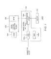
- Figure 1 is a diagram showing an example of a configuration of an engine control system 1000 according to an embodiment 1 of the present invention, which is an aspect of the present invention.
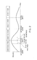
- Figure 2 is a diagram showing an example of a relationship between each stroke (crank angle) and the pressure of a cylinder of an engine 103 of the engine control system 1000 shown in Figure 1 .
- the engine control system 1000 that controls driving of the engine has an engine control unit (ECU) 100, a battery 101, a motor 102, an engine (internal combustion engine) 103, and a sensor 104.
- ECU engine control unit
- battery 101 a battery
- motor 102 a motor
- engine (internal combustion engine) 103 a sensor
- sensor 104 a sensor
- the engine 103 is a four-stroke engine, for example. Therefore, as shown in Figure 2 , the status of the engine 103 transitions through an intake stroke, a compression stroke, a combustion stroke and an exhaust stroke. As shown in Figure 2 , the pressure in the cylinder of the engine 103 (in other words, the resistance to rotation of a crank) reaches the maximum at a top dead center.
- the motor 102 is configured to apply a torque to a crank shaft of the engine 103.
- the motor 102 is connected to the crank shaft of the engine 103 in such a manner that the motor 102 can apply a torque to the crank shaft and receive a torque from the crank shaft. That is, the motor 102 functions as both an electric motor and an electric generator.
- the sensor 104 is configured to detect the number of revolutions and the crank angle of the engine 103 and output a detection signal responsive to the detection result.
- the battery 101 is configured to supply a driving power to the motor 102 and be recharged with a regenerated power from the motor 103.
- the engine control unit 100 is configured to control driving of the engine 103 by determining the status of the engine 102 based on the detection signal (more specifically, the number of revolutions and the crank angle of the engine 102 derived from the detection signal). In particular, in a case where there is a request for restart of the engine 103, the engine control unit 100 controls the operation of the engine 103 while driving the motor 102.
- the engine control unit 100 has a central processing unit (CPU) 100a, a read only memory (ROM) 100b, and a power controlling circuit 100c.
- CPU central processing unit
- ROM read only memory
- the power controlling circuit 100c is configured to control the operation of the motor 102 that applies a torque to the engine 103.
- the ROM 100b is configured to store a map used for controlling starting or other operations of the engine 103 (a map used for controlling the motor 102).
- the CPU 100a is configured to refer to the ROM 100c and control the motor 102 by controlling the power controlling circuit 100c based on the number of revolutions and the crank angle of the engine 103 detected by the sensor 101.
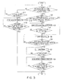
- FIG 3 is a flowchart showing an example of an engine control method according to the embodiment 1 performed by the engine control unit 100 shown in Figure 1 . That is, the engine control unit 100 performs the steps described below.
- the engine control unit 100 first determines whether or not the number of revolutions of the engine 103 is lower than a preset, prescribed number of revolutions (Step S1).
- a stop time required for the engine 103 to stop rotating (or for the number of revolutions of the engine 103 to decrease to zero) after fuel injection to the engine 103 is cut off is previously set by measurement, for example.
- Step 51 the engine control unit 100 determines that the number of revolutions of the engine 103 is lower than the prescribed number of revolutions if the stop time has elapsed since fuel injection to the engine 103 was cut off, for example.
- the engine control unit 100 determines that the number of revolutions is lower than the prescribed number of revolutions, it is determined that the number of revolutions of the engine 103 is zero, for example. In other words, if the number of revolutions is lower than the prescribed number of revolutions, it is determined that the engine 103 is stopped or about to stop.
- the engine control unit 100 determines whether or not the crank angle of the engine 103 lies in a first section between the top dead center in the compression stroke and a first angle ( Figure 2 ) (Step S2).
- the engine control unit 100 then drives the motor 102 that applies a torque to the crank of the engine 103 in the forward direction, thereby running the engine 103 in the forward direction (Step S3).
- Step S4 the engine control unit 100 determines whether or not the crank angle of the engine 103 lies in the first section ( Figure 2 ) (Step S4).
- Step S4 If the engine control unit 100 determines in Step S4 that the crank angle does not lie in the first section ( Figure 2 ), the engine control unit 100 returns to Step S3 and drives the motor 102 in the forward direction to run the engine 103 in the forward direction.
- Step S5 if the engine control unit 100 determines in Step S4 that the crank angle of the engine 103 lies in the first section ( Figure 2 ), the engine control unit 100 provides a state where there is no load on the motor 102 (a load free state) (Step S5).
- Step S2 If the engine control unit 100 determines in Step S2 that the crank angle lies in the first section ( Figure 2 ), the engine control unit 100 proceeds to Step S5 and provides the state where there is no load on the motor 102.
- Step S5 the engine control unit 100 determines whether or not the crank angle of the engine 103 lies in a second section between the top dead center in the combustion stroke and a second angle ( Figure 2 ) (Step S6).
- Step S6 If the engine control unit 100 determines in Step S6 that the crank angle does not lie in the second section ( Figure 2 ), the engine control unit 100 returns to Step S5 and continues to provide the state where there is no load on the motor 102.
- Step S7 the engine control unit 100 brakes the motor 102 (Step S7).
- the braking is implemented by making the motor 102 operate as a power generation brake such as a regenerative brake, for example.
- Step S7 the engine control unit 100 determines whether or not there is the request for restart of the engine 103 (Step S8).
- Step S8 If the engine control unit 100 determines in Step S8 that there is no request for restart of the engine 103, the engine control unit 100 returns to Step S7 and continues to provide the state where there is no load on the motor 102.
- Step S8 if the engine control unit 100 determines in Step S8 that there is the request for restart of the engine 103, the engine control unit 100 drives the motor 102 in the forward direction to run the engine 103 in the forward direction (Step S9).
- Step S9 the engine control unit 100 determines whether or not the number of revolutions of the engine 103 is equal to or higher than the starting number of revolutions at which the engine 103 starts to run (Step S10).
- Step S10 If the engine control unit 100 determines in Step S10 that the number of revolutions of the engine 103 is lower than the starting number of revolutions, the engine control unit 100 returns to Step S9 and drives the motor 102 in the forward direction to run the engine 103 in the forward direction again.
- the starting number of revolutions is the number of revolutions at which the engine 103 starts. Therefore, the prescribed number of revolutions is lower than the starting number of revolutions.
- Step S10 if the engine control unit 100 determines in Step S10 that the number of revolutions of the engine 103 is equal to or higher than the starting number of revolutions, the engine control unit 100 ends the flow.
- Step S11 If the engine control unit 100 determines in Step S1 that the number of revolutions of the engine 103 is equal to or higher than the prescribed number of revolutions, the engine control unit 100 determines whether or not there is the request for restart of the engine 103 (Step S11).
- Step S1 determines again whether or not the number of revolutions of the engine 103 is lower than the preset, prescribed number of revolutions.
- Step S11 if the engine control unit 100 determines in Step S11 that there is the request for restart of the engine 103, the engine control unit 100 drives the motor 102 in the forward direction to run the engine 103 in the forward direction (Step S12).
- Step S12 the engine control unit 100 determines whether or not the number of revolutions of the engine 103 is equal to or higher than the starting number of revolutions at which the engine 103 starts (Step S13).
- Step S13 If the engine control unit 100 determines in Step S13 that the number of revolutions of the engine 103 is lower than the starting number of revolutions, the engine control unit 100 returns to Step S12 and drives the motor 102 in the forward direction to run the engine in the forward direction again.
- Step S13 if the engine control unit 100 determines in Step S13 that the number of revolutions of the engine 103 is equal to or higher than the starting number of revolutions, the engine control unit 100 ends the flow.
- the flow described above ensures that the number of revolutions of the engine 103 is equal to or higher than the starting number of revolutions. Then, the engine 103 restarts.
- the engine control unit runs the engine 103 in the forward direction into the first section shifted from the top dead center in the compression stroke by means of the motor 102.
- the air in the cylinder of the engine is compressed to have an increased repulsive force. If the motor enters into the load free state in this state, the engine runs in the reverse direction by the action of the repulsive force.
- the engine control unit 100 brakes the motor.
- the engine control unit 100 can run the engine in the forward direction, thereby increasing the inertial force of the engine and starting the engine with higher reliability.
- the engine control method according to this embodiment can start the engine with higher reliability.
- Step S7 of the engine control method described above the inertial force of the engine can be increased by driving the motor in the reverse direction, instead of braking the motor until the request for restart occurs.
- Step S7 an example of the engine control method that drives the motor in the reverse direction until the request for restart occurs in Step S7 will be described.
- the engine control method according to the embodiment 2 is implemented by the engine control unit 100 of the engine control system 1000 according to the embodiment 1 shown in Figure 1 .
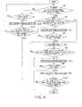
- Figure 4 is a flowchart showing the example of the engine control method according to the embodiment 2 implemented by the engine control unit 100 shown in Figure 1 .
- the same reference numerals as those in the flowchart of Figure 3 denote the same steps in Figure 3 .
- Steps S1 to S6 and S8 to S13 in the flow shown in Figure 4 are the same as those in the flow shown in Figure 3 .
- the engine control unit 100 performs Steps S1 to S6 as in the embodiment 1.
- Step S6 If the engine control unit 100 determines in Step S6 that the crank angle of the engine 103 lies in the second section, the engine control unit 100 drives the motor 102 in the reverse direction (Step S7a). In this way, the crank angle of the engine 103 is maintained in the second section.
- Step S7a the engine control unit 100 determines whether or not there is the request for restart of the engine 103 (Step S8).
- Step S8 If the engine control unit 100 determines in Step S8 that there is no request for restart of the engine 103, the engine control unit 100 returns to Step S7a and continues to drive the motor 102 in the reverse direction.
- Step S8 if the engine control unit 100 determines in Step S8 that there is the request for restart of the engine 103, the engine control unit 100 drives the motor 102 in the forward direction to run the engine 103 in the forward direction, as in the embodiment 1 (Step S9).
- the engine control unit 100 performs Steps S9, S10, and S11 to S13.
- the flow described above ensures that the number of revolutions of the engine 103 is equal to or higher than the starting number of revolutions. Then, the engine 103 restarts in response to an operation of restarting fuel injection, for example.
- the engine control unit 100 runs the engine 103 in the forward direction into the first section shifted from the top dead center in the compression stroke by means of the motor 102.
- the air in the cylinder of the engine is compressed to have an increased repulsive force. If the motor enters into the load free state in this state, the engine runs in the reverse direction by the action of the repulsive force.
- the engine control unit 100 drives the motor in the reverse direction.
- the engine control unit 100 can run the engine in the forward direction, thereby increasing the inertial force of the engine and starting the engine with higher reliability.
- the engine control method according to this embodiment can start the engine with higher reliability.
- Step S7a of the engine control method described above the inertial force of the engine can be increased by driving the motor in the reverse direction until a prescribed time elapses and then braking the motor until the request for restart occurs.
- the engine control method according to the embodiment 3 is implemented by the engine control unit 100 of the engine control system 1000 according to the embodiment 1 shown in Figure 1 .
- Figure 5 is a flowchart showing the example of the engine control method according to the embodiment 3 implemented by the engine control unit 100 shown in Figure 1 .
- the same reference numerals as those in the flowchart of Figure 4 denote the same steps in Figure 4 .
- Steps S1 to S7a and S8 to S13 in the flow shown in Figure 5 are the same as those in the flow shown in Figure 4 .
- the engine control unit 100 performs Steps S1 to S6 as in the embodiments 1 and 2.
- Step S6 if the engine control unit 100 determines in Step S6 that the crank angle of the engine 103 lies in the second section ( Figure 2 ), the engine control unit 100 drives the motor 102 in the reverse direction (Step S7a). In this way, the crank angle of the engine 103 is maintained in the second section.
- Step S7a the engine control unit 100 determines whether or not there is the request for restart of the engine 103 (Step S7b).
- Step S7b If the engine control unit 100 determines in Step S7b that there is no request for restart of the engine 103, the engine control unit 100 determines whether or not a prescribed time has elapsed since the motor 102 started being driven in the reverse direction (Step S7c).
- Step S7c If the engine control unit 100 determines in Step S7c that the prescribed time has elapsed since the motor 102 was driven in the reverse direction, the engine control unit 100 proceeds to Step S7 and brakes the motor 102. In this way, the motor 102 can be prevented from continuing to be driven in the reverse direction despite there being no request for restart for a long time and wasting electric power.
- Step S7c determines in Step S7c that the prescribed time has not elapsed since the motor 102 starts being driven in the reverse direction
- the engine control unit 100 returns to Step S7a and drives the motor 102 in the reverse direction again.
- Step S7b If the engine control unit 100 determines in Step S7b that there is the request for restart of the engine 103, the engine control unit 100 proceeds to Step S9 and drives the motor 102 in the forward direction to run the engine 103 in the forward direction.
- the engine control unit 100 performs Steps S9, S10, and S11 to S13.
- the flow described above ensures that the number of revolutions of the engine 103 is equal to or higher than the starting number of revolutions. Then, the engine 103 restarts.
- the engine control unit 100 runs the engine 103 in the forward direction into the first section shifted from the top dead center in the compression stroke by means of the motor 102.
- the air in the cylinder of the engine is compressed to have an increased repulsive force. If the motor enters into the load free state in this state, the engine runs in the reverse direction by the action of the repulsive force.
- the engine control unit 100 drives the motor in the reverse direction as in the embodiment 2.
- the engine control unit 100 brakes the motor.
- the engine control unit 100 can run the engine in the forward direction, thereby increasing the inertial force of the engine and starting the engine with higher reliability.
- the engine control method according to this embodiment can start the engine with higher reliability.
- Figure 1 shows the engine 103 and the motor 102 integrated with each other, the engine 103 and the motor 102 may be separated from each other.
- the motor 102 functions as both an electric motor and an electric generator.
- the effects and advantages of the present invention can be provided even if the motor 102 is connected to the crank shaft of the engine 103 to apply a torque thereto and functions only as an electric motor.
- a separate motor that functions as an electric generator can be used.
Landscapes
- Engineering & Computer Science (AREA)
- Chemical & Material Sciences (AREA)
- Combustion & Propulsion (AREA)
- Mechanical Engineering (AREA)
- General Engineering & Computer Science (AREA)
- Control Of Vehicle Engines Or Engines For Specific Uses (AREA)
- Hybrid Electric Vehicles (AREA)
- Combined Controls Of Internal Combustion Engines (AREA)
- Electric Propulsion And Braking For Vehicles (AREA)
- Output Control And Ontrol Of Special Type Engine (AREA)
Applications Claiming Priority (2)
| Application Number | Priority Date | Filing Date | Title |
|---|---|---|---|
| JP2010208166 | 2010-09-16 | ||
| PCT/JP2011/070939 WO2012036184A1 (fr) | 2010-09-16 | 2011-09-14 | Unité de commande d'entraînement, système de commande d'entraînement et procédé de commande d'entraînement |
Publications (3)
| Publication Number | Publication Date |
|---|---|
| EP2617983A1 true EP2617983A1 (fr) | 2013-07-24 |
| EP2617983A4 EP2617983A4 (fr) | 2017-01-11 |
| EP2617983B1 EP2617983B1 (fr) | 2024-02-14 |
Family
ID=45831641
Family Applications (1)
| Application Number | Title | Priority Date | Filing Date |
|---|---|---|---|
| EP11825184.2A Active EP2617983B1 (fr) | 2010-09-16 | 2011-09-14 | Méthode de contrôle et unité de contrôle d'un moteur |
Country Status (6)
| Country | Link |
|---|---|
| US (2) | US9291111B2 (fr) |
| EP (1) | EP2617983B1 (fr) |
| JP (1) | JP5283786B2 (fr) |
| CN (1) | CN102859181B (fr) |
| IN (1) | IN2012DN06699A (fr) |
| WO (1) | WO2012036184A1 (fr) |
Families Citing this family (9)
| Publication number | Priority date | Publication date | Assignee | Title |
|---|---|---|---|---|
| WO2012036184A1 (fr) * | 2010-09-16 | 2012-03-22 | 新電元工業株式会社 | Unité de commande d'entraînement, système de commande d'entraînement et procédé de commande d'entraînement |
| EP2858232B1 (fr) * | 2012-05-29 | 2018-08-22 | Shindengen Electric Manufacturing Co. Ltd. | Dispositif de commande d'entraînement et procédé de commande de production d'énergie |
| JP2017031808A (ja) * | 2013-12-20 | 2017-02-09 | ヤマハ発動機株式会社 | エンジンユニット、及び車両 |
| WO2015093577A1 (fr) * | 2013-12-20 | 2015-06-25 | ヤマハ発動機株式会社 | Unité de moteur et véhicule |
| JP6002269B1 (ja) * | 2015-03-30 | 2016-10-05 | 本田技研工業株式会社 | 車両用エンジンの始動装置 |
| WO2016193999A2 (fr) * | 2015-06-05 | 2016-12-08 | Sedemac Mechatronics Pvt Ltd | Système de démarrage pour moteur à combustion interne et procédé associé |
| BR112019019448A2 (pt) * | 2017-03-28 | 2020-04-14 | Honda Motor Co Ltd | dispositivo de controle de partida de motor |
| US11280307B2 (en) * | 2017-11-13 | 2022-03-22 | India Nippon Electricals Limited | Engine drive system |
| US11391256B2 (en) * | 2020-08-05 | 2022-07-19 | Ford Global Technologies, Llc | Methods and system for controlling engine stop position |
Family Cites Families (33)
| Publication number | Priority date | Publication date | Assignee | Title |
|---|---|---|---|---|
| JPS60195342A (ja) * | 1984-03-19 | 1985-10-03 | Hitachi Ltd | エンジン制御装置 |
| JP2810039B2 (ja) * | 1987-04-08 | 1998-10-15 | 株式会社日立製作所 | フィードフォワード型燃料供給方法 |
| DE3923237C2 (de) * | 1988-08-03 | 1994-01-27 | Stihl Maschf Andreas | Zündschaltung für einen Verbrennungsmotor |
| JPH033969A (ja) | 1989-05-30 | 1991-01-10 | Mazda Motor Corp | エンジンの始動制御装置 |
| JPH04214947A (ja) * | 1990-12-14 | 1992-08-05 | Toyota Motor Corp | 内燃機関のトルク変動制御装置 |
| JP3096941B2 (ja) | 1992-09-22 | 2000-10-10 | キヤノン株式会社 | 原稿搬送装置 |
| JP3351042B2 (ja) * | 1993-09-02 | 2002-11-25 | 株式会社デンソー | 車両用内燃機関始動装置 |
| JPH0828338A (ja) * | 1994-07-11 | 1996-01-30 | Unisia Jecs Corp | 内燃機関のクランク角位置検出装置及び制御装置 |
| US6223730B1 (en) * | 1997-11-27 | 2001-05-01 | Denso Corporation | Fuel injection control system of internal combustion engine |
| WO2002027182A1 (fr) * | 2000-09-28 | 2002-04-04 | Mitsuba Corporation | Demarreur de moteur |
| JP3824132B2 (ja) | 2000-10-26 | 2006-09-20 | 本田技研工業株式会社 | エンジン始動制御装置 |
| US6453864B1 (en) * | 2001-01-16 | 2002-09-24 | General Motors Corporation | Crankshaft rotation control in a hybrid electric vehicle |
| JP4039604B2 (ja) | 2001-05-09 | 2008-01-30 | 本田技研工業株式会社 | 小型二輪車用のエンジン始動装置 |
| JP3969641B2 (ja) * | 2002-05-22 | 2007-09-05 | 本田技研工業株式会社 | エンジン始動装置 |
| EP1422421B1 (fr) * | 2002-11-25 | 2010-11-24 | Ford Global Technologies, LLC | Méthode et dispositif d'arrêt et de redémarrage d'un moteur à combustion interne |
| EP1422420B1 (fr) * | 2002-11-25 | 2009-06-03 | Ford Global Technologies, LLC | Mécanisme de blocage pour le vilebrequin d'un moteur à combustion interne |
| JP3815441B2 (ja) * | 2003-02-04 | 2006-08-30 | トヨタ自動車株式会社 | 内燃機関の停止始動制御装置 |
| JP2005299481A (ja) | 2004-04-09 | 2005-10-27 | Mitsubishi Motors Corp | 筒内噴射型内燃機関の始動装置 |
| JP4516401B2 (ja) * | 2004-10-18 | 2010-08-04 | 日立オートモティブシステムズ株式会社 | エンジンの始動制御装置 |
| JP4137045B2 (ja) * | 2004-11-09 | 2008-08-20 | 株式会社ケーヒン | 4サイクルエンジン用加減速検知装置及び方法 |
| JP4506493B2 (ja) | 2005-02-08 | 2010-07-21 | トヨタ自動車株式会社 | 内燃機関の制御装置 |
| US7278388B2 (en) | 2005-05-12 | 2007-10-09 | Ford Global Technologies, Llc | Engine starting for engine having adjustable valve operation |
| EP2267286A1 (fr) | 2005-09-01 | 2010-12-29 | AVL List GmbH | Procédé de commande d'un moteur à combustion |
| JP2007132335A (ja) | 2005-10-11 | 2007-05-31 | Kokusan Denki Co Ltd | エンジン始動装置 |
| JP4749981B2 (ja) * | 2005-12-28 | 2011-08-17 | 日立オートモティブシステムズ株式会社 | 内燃機関の可変動弁装置 |
| US20070204827A1 (en) * | 2006-03-02 | 2007-09-06 | Kokusan Denki Co., Ltd. | Engine starting device |
| JP4682966B2 (ja) * | 2006-11-06 | 2011-05-11 | 国産電機株式会社 | エンジン始動方法及び装置 |
| JP4834519B2 (ja) * | 2006-11-10 | 2011-12-14 | アイシン精機株式会社 | 車両の駆動源制御装置 |
| JP4254852B2 (ja) | 2006-12-06 | 2009-04-15 | トヨタ自動車株式会社 | 車両およびその制御方法 |
| JP2008163818A (ja) | 2006-12-28 | 2008-07-17 | Hitachi Ltd | スタータ |
| JP5361590B2 (ja) * | 2009-07-21 | 2013-12-04 | 本田技研工業株式会社 | エンジン始動制御装置 |
| WO2012036184A1 (fr) * | 2010-09-16 | 2012-03-22 | 新電元工業株式会社 | Unité de commande d'entraînement, système de commande d'entraînement et procédé de commande d'entraînement |
| US9074529B2 (en) * | 2012-06-26 | 2015-07-07 | Shindengen Electric Manufacturing Co., Ltd. | Drive controlling apparatus and drive controlling method |
-
2011
- 2011-09-14 WO PCT/JP2011/070939 patent/WO2012036184A1/fr not_active Ceased
- 2011-09-14 US US13/823,737 patent/US9291111B2/en active Active
- 2011-09-14 EP EP11825184.2A patent/EP2617983B1/fr active Active
- 2011-09-14 JP JP2012534028A patent/JP5283786B2/ja active Active
- 2011-09-14 CN CN201180020454.XA patent/CN102859181B/zh active Active
-
2012
- 2012-07-30 IN IN6699DEN2012 patent/IN2012DN06699A/en unknown
- 2012-10-30 US US13/664,306 patent/US20130060455A1/en not_active Abandoned
Also Published As
| Publication number | Publication date |
|---|---|
| JPWO2012036184A1 (ja) | 2014-02-03 |
| EP2617983A4 (fr) | 2017-01-11 |
| US9291111B2 (en) | 2016-03-22 |
| US20130180501A1 (en) | 2013-07-18 |
| CN102859181B (zh) | 2015-03-04 |
| CN102859181A (zh) | 2013-01-02 |
| IN2012DN06699A (fr) | 2015-10-23 |
| EP2617983B1 (fr) | 2024-02-14 |
| WO2012036184A1 (fr) | 2012-03-22 |
| US20130060455A1 (en) | 2013-03-07 |
| JP5283786B2 (ja) | 2013-09-04 |
Similar Documents
| Publication | Publication Date | Title |
|---|---|---|
| US9291111B2 (en) | Engine control unit, engine control system and engine control method | |
| CN102667414B (zh) | 旋转传感器的异常判断装置 | |
| US9074529B2 (en) | Drive controlling apparatus and drive controlling method | |
| US9353692B2 (en) | Start-up strategy for hybrid powertrain | |
| CN101846002A (zh) | 车辆控制装置以及怠速停止系统 | |
| US8292778B2 (en) | Idle-stop restart control system | |
| US11136930B2 (en) | Engine start control device | |
| EP3147495A1 (fr) | Procédé de commande de démarrage/arrêt du moteur | |
| CN106536917B (zh) | 用于起动内燃机的方法 | |
| JP2019027367A5 (fr) | ||
| CN106401832A (zh) | 启动兼发电装置控制引擎起动的方法 | |
| JP2018527502A (ja) | 始動および停止システムにおける内燃エンジンの再始動を管理するプロセス | |
| JP2001263147A (ja) | エンジンの停止判定装置および再始動装置 | |
| CN107035551A (zh) | 引擎熄火制动控制方法 | |
| JP5059043B2 (ja) | エンジン停止始動制御装置 | |
| US20180142659A1 (en) | Control device for vehicle | |
| CN105452075B (zh) | 包括电动真空产生设备的机动车辆 | |
| TWI288206B (en) | Control device and method for preventing the engine restarting | |
| US8872483B2 (en) | Drive controlling apparatus and power generation controlling method | |
| EP3754176B1 (fr) | Procédé de commande pour moteur à combustion interne et dispositif de commande pour moteur à combustion interne | |
| WO2015146350A1 (fr) | Dispositif de commande de moteur électrique | |
| TWI905926B (zh) | 機車引擎的輔助系統及其方法 | |
| CN112253350B (zh) | 发动机起动方法及用此方法的起动系统 | |
| CN102918256B (zh) | 热力发动机的起动方法和控制装置 | |
| TH2101001516A (th) | อุปกรณ์สตาร์ตใหม่เครื่องยนต์ |
Legal Events
| Date | Code | Title | Description |
|---|---|---|---|
| PUAI | Public reference made under article 153(3) epc to a published international application that has entered the european phase |
Free format text: ORIGINAL CODE: 0009012 |
|
| 17P | Request for examination filed |
Effective date: 20120719 |
|
| AK | Designated contracting states |
Kind code of ref document: A1 Designated state(s): AL AT BE BG CH CY CZ DE DK EE ES FI FR GB GR HR HU IE IS IT LI LT LU LV MC MK MT NL NO PL PT RO RS SE SI SK SM TR |
|
| DAX | Request for extension of the european patent (deleted) | ||
| RA4 | Supplementary search report drawn up and despatched (corrected) |
Effective date: 20161208 |
|
| RIC1 | Information provided on ipc code assigned before grant |
Ipc: F02N 11/08 20060101AFI20161202BHEP |
|
| STAA | Information on the status of an ep patent application or granted ep patent |
Free format text: STATUS: EXAMINATION IS IN PROGRESS |
|
| 17Q | First examination report despatched |
Effective date: 20200731 |
|
| REG | Reference to a national code |
Ref country code: DE Free format text: PREVIOUS MAIN CLASS: F02N0011080000 Ipc: F02N0011040000 Ref country code: DE Ref legal event code: R079 Ref document number: 602011074575 Country of ref document: DE Free format text: PREVIOUS MAIN CLASS: F02N0011080000 Ipc: F02N0011040000 |
|
| GRAP | Despatch of communication of intention to grant a patent |
Free format text: ORIGINAL CODE: EPIDOSNIGR1 |
|
| STAA | Information on the status of an ep patent application or granted ep patent |
Free format text: STATUS: GRANT OF PATENT IS INTENDED |
|
| RIC1 | Information provided on ipc code assigned before grant |
Ipc: F02D 41/00 20060101ALN20230809BHEP Ipc: F02D 41/06 20060101ALI20230809BHEP Ipc: F02N 19/00 20100101ALI20230809BHEP Ipc: F02N 11/08 20060101ALI20230809BHEP Ipc: F02D 41/04 20060101ALI20230809BHEP Ipc: F02N 11/04 20060101AFI20230809BHEP |
|
| INTG | Intention to grant announced |
Effective date: 20230828 |
|
| GRAS | Grant fee paid |
Free format text: ORIGINAL CODE: EPIDOSNIGR3 |
|
| GRAA | (expected) grant |
Free format text: ORIGINAL CODE: 0009210 |
|
| STAA | Information on the status of an ep patent application or granted ep patent |
Free format text: STATUS: THE PATENT HAS BEEN GRANTED |
|
| AK | Designated contracting states |
Kind code of ref document: B1 Designated state(s): AL AT BE BG CH CY CZ DE DK EE ES FI FR GB GR HR HU IE IS IT LI LT LU LV MC MK MT NL NO PL PT RO RS SE SI SK SM TR |
|
| REG | Reference to a national code |
Ref country code: GB Ref legal event code: FG4D |
|
| REG | Reference to a national code |
Ref country code: CH Ref legal event code: EP |
|
| REG | Reference to a national code |
Ref country code: DE Ref legal event code: R096 Ref document number: 602011074575 Country of ref document: DE |
|
| REG | Reference to a national code |
Ref country code: IE Ref legal event code: FG4D |
|
| REG | Reference to a national code |
Ref country code: LT Ref legal event code: MG9D |
|
| REG | Reference to a national code |
Ref country code: NL Ref legal event code: MP Effective date: 20240214 |
|
| PG25 | Lapsed in a contracting state [announced via postgrant information from national office to epo] |
Ref country code: IS Free format text: LAPSE BECAUSE OF FAILURE TO SUBMIT A TRANSLATION OF THE DESCRIPTION OR TO PAY THE FEE WITHIN THE PRESCRIBED TIME-LIMIT Effective date: 20240614 |
|
| PG25 | Lapsed in a contracting state [announced via postgrant information from national office to epo] |
Ref country code: LT Free format text: LAPSE BECAUSE OF FAILURE TO SUBMIT A TRANSLATION OF THE DESCRIPTION OR TO PAY THE FEE WITHIN THE PRESCRIBED TIME-LIMIT Effective date: 20240214 |
|
| PG25 | Lapsed in a contracting state [announced via postgrant information from national office to epo] |
Ref country code: GR Free format text: LAPSE BECAUSE OF FAILURE TO SUBMIT A TRANSLATION OF THE DESCRIPTION OR TO PAY THE FEE WITHIN THE PRESCRIBED TIME-LIMIT Effective date: 20240515 |
|
| REG | Reference to a national code |
Ref country code: AT Ref legal event code: MK05 Ref document number: 1657205 Country of ref document: AT Kind code of ref document: T Effective date: 20240214 |
|
| PG25 | Lapsed in a contracting state [announced via postgrant information from national office to epo] |
Ref country code: HR Free format text: LAPSE BECAUSE OF FAILURE TO SUBMIT A TRANSLATION OF THE DESCRIPTION OR TO PAY THE FEE WITHIN THE PRESCRIBED TIME-LIMIT Effective date: 20240214 Ref country code: RS Free format text: LAPSE BECAUSE OF FAILURE TO SUBMIT A TRANSLATION OF THE DESCRIPTION OR TO PAY THE FEE WITHIN THE PRESCRIBED TIME-LIMIT Effective date: 20240514 Ref country code: NL Free format text: LAPSE BECAUSE OF FAILURE TO SUBMIT A TRANSLATION OF THE DESCRIPTION OR TO PAY THE FEE WITHIN THE PRESCRIBED TIME-LIMIT Effective date: 20240214 |
|
| PG25 | Lapsed in a contracting state [announced via postgrant information from national office to epo] |
Ref country code: ES Free format text: LAPSE BECAUSE OF FAILURE TO SUBMIT A TRANSLATION OF THE DESCRIPTION OR TO PAY THE FEE WITHIN THE PRESCRIBED TIME-LIMIT Effective date: 20240214 |
|
| PG25 | Lapsed in a contracting state [announced via postgrant information from national office to epo] |
Ref country code: AT Free format text: LAPSE BECAUSE OF FAILURE TO SUBMIT A TRANSLATION OF THE DESCRIPTION OR TO PAY THE FEE WITHIN THE PRESCRIBED TIME-LIMIT Effective date: 20240214 |
|
| PG25 | Lapsed in a contracting state [announced via postgrant information from national office to epo] |
Ref country code: RS Free format text: LAPSE BECAUSE OF FAILURE TO SUBMIT A TRANSLATION OF THE DESCRIPTION OR TO PAY THE FEE WITHIN THE PRESCRIBED TIME-LIMIT Effective date: 20240514 Ref country code: NO Free format text: LAPSE BECAUSE OF FAILURE TO SUBMIT A TRANSLATION OF THE DESCRIPTION OR TO PAY THE FEE WITHIN THE PRESCRIBED TIME-LIMIT Effective date: 20240514 Ref country code: NL Free format text: LAPSE BECAUSE OF FAILURE TO SUBMIT A TRANSLATION OF THE DESCRIPTION OR TO PAY THE FEE WITHIN THE PRESCRIBED TIME-LIMIT Effective date: 20240214 Ref country code: LT Free format text: LAPSE BECAUSE OF FAILURE TO SUBMIT A TRANSLATION OF THE DESCRIPTION OR TO PAY THE FEE WITHIN THE PRESCRIBED TIME-LIMIT Effective date: 20240214 Ref country code: IS Free format text: LAPSE BECAUSE OF FAILURE TO SUBMIT A TRANSLATION OF THE DESCRIPTION OR TO PAY THE FEE WITHIN THE PRESCRIBED TIME-LIMIT Effective date: 20240614 Ref country code: HR Free format text: LAPSE BECAUSE OF FAILURE TO SUBMIT A TRANSLATION OF THE DESCRIPTION OR TO PAY THE FEE WITHIN THE PRESCRIBED TIME-LIMIT Effective date: 20240214 Ref country code: GR Free format text: LAPSE BECAUSE OF FAILURE TO SUBMIT A TRANSLATION OF THE DESCRIPTION OR TO PAY THE FEE WITHIN THE PRESCRIBED TIME-LIMIT Effective date: 20240515 Ref country code: FI Free format text: LAPSE BECAUSE OF FAILURE TO SUBMIT A TRANSLATION OF THE DESCRIPTION OR TO PAY THE FEE WITHIN THE PRESCRIBED TIME-LIMIT Effective date: 20240214 Ref country code: ES Free format text: LAPSE BECAUSE OF FAILURE TO SUBMIT A TRANSLATION OF THE DESCRIPTION OR TO PAY THE FEE WITHIN THE PRESCRIBED TIME-LIMIT Effective date: 20240214 Ref country code: BG Free format text: LAPSE BECAUSE OF FAILURE TO SUBMIT A TRANSLATION OF THE DESCRIPTION OR TO PAY THE FEE WITHIN THE PRESCRIBED TIME-LIMIT Effective date: 20240214 Ref country code: AT Free format text: LAPSE BECAUSE OF FAILURE TO SUBMIT A TRANSLATION OF THE DESCRIPTION OR TO PAY THE FEE WITHIN THE PRESCRIBED TIME-LIMIT Effective date: 20240214 |
|
| PG25 | Lapsed in a contracting state [announced via postgrant information from national office to epo] |
Ref country code: PL Free format text: LAPSE BECAUSE OF FAILURE TO SUBMIT A TRANSLATION OF THE DESCRIPTION OR TO PAY THE FEE WITHIN THE PRESCRIBED TIME-LIMIT Effective date: 20240214 Ref country code: PT Free format text: LAPSE BECAUSE OF FAILURE TO SUBMIT A TRANSLATION OF THE DESCRIPTION OR TO PAY THE FEE WITHIN THE PRESCRIBED TIME-LIMIT Effective date: 20240614 |
|
| PG25 | Lapsed in a contracting state [announced via postgrant information from national office to epo] |
Ref country code: SE Free format text: LAPSE BECAUSE OF FAILURE TO SUBMIT A TRANSLATION OF THE DESCRIPTION OR TO PAY THE FEE WITHIN THE PRESCRIBED TIME-LIMIT Effective date: 20240214 Ref country code: PT Free format text: LAPSE BECAUSE OF FAILURE TO SUBMIT A TRANSLATION OF THE DESCRIPTION OR TO PAY THE FEE WITHIN THE PRESCRIBED TIME-LIMIT Effective date: 20240614 Ref country code: PL Free format text: LAPSE BECAUSE OF FAILURE TO SUBMIT A TRANSLATION OF THE DESCRIPTION OR TO PAY THE FEE WITHIN THE PRESCRIBED TIME-LIMIT Effective date: 20240214 Ref country code: LV Free format text: LAPSE BECAUSE OF FAILURE TO SUBMIT A TRANSLATION OF THE DESCRIPTION OR TO PAY THE FEE WITHIN THE PRESCRIBED TIME-LIMIT Effective date: 20240214 |
|
| PG25 | Lapsed in a contracting state [announced via postgrant information from national office to epo] |
Ref country code: DK Free format text: LAPSE BECAUSE OF FAILURE TO SUBMIT A TRANSLATION OF THE DESCRIPTION OR TO PAY THE FEE WITHIN THE PRESCRIBED TIME-LIMIT Effective date: 20240214 |
|
| PG25 | Lapsed in a contracting state [announced via postgrant information from national office to epo] |
Ref country code: SM Free format text: LAPSE BECAUSE OF FAILURE TO SUBMIT A TRANSLATION OF THE DESCRIPTION OR TO PAY THE FEE WITHIN THE PRESCRIBED TIME-LIMIT Effective date: 20240214 |
|
| PG25 | Lapsed in a contracting state [announced via postgrant information from national office to epo] |
Ref country code: EE Free format text: LAPSE BECAUSE OF FAILURE TO SUBMIT A TRANSLATION OF THE DESCRIPTION OR TO PAY THE FEE WITHIN THE PRESCRIBED TIME-LIMIT Effective date: 20240214 Ref country code: CZ Free format text: LAPSE BECAUSE OF FAILURE TO SUBMIT A TRANSLATION OF THE DESCRIPTION OR TO PAY THE FEE WITHIN THE PRESCRIBED TIME-LIMIT Effective date: 20240214 |
|
| PG25 | Lapsed in a contracting state [announced via postgrant information from national office to epo] |
Ref country code: SK Free format text: LAPSE BECAUSE OF FAILURE TO SUBMIT A TRANSLATION OF THE DESCRIPTION OR TO PAY THE FEE WITHIN THE PRESCRIBED TIME-LIMIT Effective date: 20240214 |
|
| PG25 | Lapsed in a contracting state [announced via postgrant information from national office to epo] |
Ref country code: SM Free format text: LAPSE BECAUSE OF FAILURE TO SUBMIT A TRANSLATION OF THE DESCRIPTION OR TO PAY THE FEE WITHIN THE PRESCRIBED TIME-LIMIT Effective date: 20240214 Ref country code: SK Free format text: LAPSE BECAUSE OF FAILURE TO SUBMIT A TRANSLATION OF THE DESCRIPTION OR TO PAY THE FEE WITHIN THE PRESCRIBED TIME-LIMIT Effective date: 20240214 Ref country code: RO Free format text: LAPSE BECAUSE OF FAILURE TO SUBMIT A TRANSLATION OF THE DESCRIPTION OR TO PAY THE FEE WITHIN THE PRESCRIBED TIME-LIMIT Effective date: 20240214 Ref country code: EE Free format text: LAPSE BECAUSE OF FAILURE TO SUBMIT A TRANSLATION OF THE DESCRIPTION OR TO PAY THE FEE WITHIN THE PRESCRIBED TIME-LIMIT Effective date: 20240214 Ref country code: DK Free format text: LAPSE BECAUSE OF FAILURE TO SUBMIT A TRANSLATION OF THE DESCRIPTION OR TO PAY THE FEE WITHIN THE PRESCRIBED TIME-LIMIT Effective date: 20240214 Ref country code: CZ Free format text: LAPSE BECAUSE OF FAILURE TO SUBMIT A TRANSLATION OF THE DESCRIPTION OR TO PAY THE FEE WITHIN THE PRESCRIBED TIME-LIMIT Effective date: 20240214 |
|
| REG | Reference to a national code |
Ref country code: DE Ref legal event code: R097 Ref document number: 602011074575 Country of ref document: DE |
|
| PLBE | No opposition filed within time limit |
Free format text: ORIGINAL CODE: 0009261 |
|
| STAA | Information on the status of an ep patent application or granted ep patent |
Free format text: STATUS: NO OPPOSITION FILED WITHIN TIME LIMIT |
|
| 26N | No opposition filed |
Effective date: 20241115 |
|
| REG | Reference to a national code |
Ref country code: DE Ref legal event code: R119 Ref document number: 602011074575 Country of ref document: DE |
|
| PG25 | Lapsed in a contracting state [announced via postgrant information from national office to epo] |
Ref country code: MC Free format text: LAPSE BECAUSE OF FAILURE TO SUBMIT A TRANSLATION OF THE DESCRIPTION OR TO PAY THE FEE WITHIN THE PRESCRIBED TIME-LIMIT Effective date: 20240214 Ref country code: SI Free format text: LAPSE BECAUSE OF FAILURE TO SUBMIT A TRANSLATION OF THE DESCRIPTION OR TO PAY THE FEE WITHIN THE PRESCRIBED TIME-LIMIT Effective date: 20240214 |
|
| REG | Reference to a national code |
Ref country code: CH Ref legal event code: PL |
|
| PG25 | Lapsed in a contracting state [announced via postgrant information from national office to epo] |
Ref country code: LU Free format text: LAPSE BECAUSE OF NON-PAYMENT OF DUE FEES Effective date: 20240914 |
|
| GBPC | Gb: european patent ceased through non-payment of renewal fee |
Effective date: 20240914 |
|
| PG25 | Lapsed in a contracting state [announced via postgrant information from national office to epo] |
Ref country code: DE Free format text: LAPSE BECAUSE OF NON-PAYMENT OF DUE FEES Effective date: 20250401 |
|
| PG25 | Lapsed in a contracting state [announced via postgrant information from national office to epo] |
Ref country code: GB Free format text: LAPSE BECAUSE OF NON-PAYMENT OF DUE FEES Effective date: 20240914 |
|
| REG | Reference to a national code |
Ref country code: BE Ref legal event code: MM Effective date: 20240930 |
|
| PG25 | Lapsed in a contracting state [announced via postgrant information from national office to epo] |
Ref country code: BE Free format text: LAPSE BECAUSE OF NON-PAYMENT OF DUE FEES Effective date: 20240930 |
|
| PG25 | Lapsed in a contracting state [announced via postgrant information from national office to epo] |
Ref country code: FR Free format text: LAPSE BECAUSE OF NON-PAYMENT OF DUE FEES Effective date: 20240930 |
|
| PG25 | Lapsed in a contracting state [announced via postgrant information from national office to epo] |
Ref country code: CH Free format text: LAPSE BECAUSE OF NON-PAYMENT OF DUE FEES Effective date: 20240930 |
|
| PG25 | Lapsed in a contracting state [announced via postgrant information from national office to epo] |
Ref country code: IE Free format text: LAPSE BECAUSE OF NON-PAYMENT OF DUE FEES Effective date: 20240914 |
|
| PGFP | Annual fee paid to national office [announced via postgrant information from national office to epo] |
Ref country code: IT Payment date: 20250924 Year of fee payment: 15 |
|
| PG25 | Lapsed in a contracting state [announced via postgrant information from national office to epo] |
Ref country code: CY Free format text: LAPSE BECAUSE OF FAILURE TO SUBMIT A TRANSLATION OF THE DESCRIPTION OR TO PAY THE FEE WITHIN THE PRESCRIBED TIME-LIMIT; INVALID AB INITIO Effective date: 20110914 |
|
| PG25 | Lapsed in a contracting state [announced via postgrant information from national office to epo] |
Ref country code: HU Free format text: LAPSE BECAUSE OF FAILURE TO SUBMIT A TRANSLATION OF THE DESCRIPTION OR TO PAY THE FEE WITHIN THE PRESCRIBED TIME-LIMIT; INVALID AB INITIO Effective date: 20110914 |