EP2617992A2 - Éolienne à axe vertical - Google Patents
Éolienne à axe vertical Download PDFInfo
- Publication number
- EP2617992A2 EP2617992A2 EP13163789.4A EP13163789A EP2617992A2 EP 2617992 A2 EP2617992 A2 EP 2617992A2 EP 13163789 A EP13163789 A EP 13163789A EP 2617992 A2 EP2617992 A2 EP 2617992A2
- Authority
- EP
- European Patent Office
- Prior art keywords
- wind power
- vertical axis
- axis type
- type wind
- power station
- Prior art date
- Legal status (The legal status is an assumption and is not a legal conclusion. Google has not performed a legal analysis and makes no representation as to the accuracy of the status listed.)
- Withdrawn
Links
- 229910000838 Al alloy Inorganic materials 0.000 claims description 13
- 238000000034 method Methods 0.000 claims description 11
- 230000008569 process Effects 0.000 claims description 5
- 230000037368 penetrate the skin Effects 0.000 claims description 2
- 230000033001 locomotion Effects 0.000 abstract description 13
- 238000010248 power generation Methods 0.000 abstract description 7
- 238000004519 manufacturing process Methods 0.000 abstract description 2
- 238000010586 diagram Methods 0.000 description 41
- 238000005452 bending Methods 0.000 description 29
- 230000005484 gravity Effects 0.000 description 18
- 238000010276 construction Methods 0.000 description 13
- 229920001084 poly(chloroprene) Polymers 0.000 description 9
- 230000000694 effects Effects 0.000 description 8
- 230000007246 mechanism Effects 0.000 description 8
- 230000004048 modification Effects 0.000 description 6
- 238000012986 modification Methods 0.000 description 6
- 239000004568 cement Substances 0.000 description 5
- 230000005611 electricity Effects 0.000 description 5
- 238000009434 installation Methods 0.000 description 3
- 239000000463 material Substances 0.000 description 3
- 230000002093 peripheral effect Effects 0.000 description 3
- 239000011435 rock Substances 0.000 description 3
- 238000003466 welding Methods 0.000 description 3
- 239000003365 glass fiber Substances 0.000 description 2
- 238000003825 pressing Methods 0.000 description 2
- 239000011150 reinforced concrete Substances 0.000 description 2
- 239000000565 sealant Substances 0.000 description 2
- XLYOFNOQVPJJNP-UHFFFAOYSA-N water Substances O XLYOFNOQVPJJNP-UHFFFAOYSA-N 0.000 description 2
- 230000037303 wrinkles Effects 0.000 description 2
- 229910052782 aluminium Inorganic materials 0.000 description 1
- XAGFODPZIPBFFR-UHFFFAOYSA-N aluminium Chemical compound [Al] XAGFODPZIPBFFR-UHFFFAOYSA-N 0.000 description 1
- 238000003491 array Methods 0.000 description 1
- 238000007664 blowing Methods 0.000 description 1
- 239000004567 concrete Substances 0.000 description 1
- 229920001971 elastomer Polymers 0.000 description 1
- 230000007613 environmental effect Effects 0.000 description 1
- 230000014759 maintenance of location Effects 0.000 description 1
- 230000013011 mating Effects 0.000 description 1
- 229910052751 metal Inorganic materials 0.000 description 1
- 239000002184 metal Substances 0.000 description 1
- APTZNLHMIGJTEW-UHFFFAOYSA-N pyraflufen-ethyl Chemical compound C1=C(Cl)C(OCC(=O)OCC)=CC(C=2C(=C(OC(F)F)N(C)N=2)Cl)=C1F APTZNLHMIGJTEW-UHFFFAOYSA-N 0.000 description 1
- 230000009467 reduction Effects 0.000 description 1
- 239000002689 soil Substances 0.000 description 1
- 230000008719 thickening Effects 0.000 description 1
- 238000010792 warming Methods 0.000 description 1
Images

















Classifications
-
- F—MECHANICAL ENGINEERING; LIGHTING; HEATING; WEAPONS; BLASTING
- F03—MACHINES OR ENGINES FOR LIQUIDS; WIND, SPRING, OR WEIGHT MOTORS; PRODUCING MECHANICAL POWER OR A REACTIVE PROPULSIVE THRUST, NOT OTHERWISE PROVIDED FOR
- F03D—WIND MOTORS
- F03D3/00—Wind motors with rotation axis substantially perpendicular to the air flow entering the rotor
- F03D3/06—Rotors
- F03D3/061—Rotors characterised by their aerodynamic shape, e.g. aerofoil profiles
-
- F—MECHANICAL ENGINEERING; LIGHTING; HEATING; WEAPONS; BLASTING
- F03—MACHINES OR ENGINES FOR LIQUIDS; WIND, SPRING, OR WEIGHT MOTORS; PRODUCING MECHANICAL POWER OR A REACTIVE PROPULSIVE THRUST, NOT OTHERWISE PROVIDED FOR
- F03D—WIND MOTORS
- F03D3/00—Wind motors with rotation axis substantially perpendicular to the air flow entering the rotor
- F03D3/005—Wind motors with rotation axis substantially perpendicular to the air flow entering the rotor the axis being vertical
-
- F—MECHANICAL ENGINEERING; LIGHTING; HEATING; WEAPONS; BLASTING
- F03—MACHINES OR ENGINES FOR LIQUIDS; WIND, SPRING, OR WEIGHT MOTORS; PRODUCING MECHANICAL POWER OR A REACTIVE PROPULSIVE THRUST, NOT OTHERWISE PROVIDED FOR
- F03D—WIND MOTORS
- F03D3/00—Wind motors with rotation axis substantially perpendicular to the air flow entering the rotor
- F03D3/06—Rotors
- F03D3/062—Rotors characterised by their construction elements
-
- F—MECHANICAL ENGINEERING; LIGHTING; HEATING; WEAPONS; BLASTING
- F03—MACHINES OR ENGINES FOR LIQUIDS; WIND, SPRING, OR WEIGHT MOTORS; PRODUCING MECHANICAL POWER OR A REACTIVE PROPULSIVE THRUST, NOT OTHERWISE PROVIDED FOR
- F03D—WIND MOTORS
- F03D3/00—Wind motors with rotation axis substantially perpendicular to the air flow entering the rotor
- F03D3/06—Rotors
- F03D3/062—Rotors characterised by their construction elements
- F03D3/064—Fixing wind engaging parts to rest of rotor
-
- F—MECHANICAL ENGINEERING; LIGHTING; HEATING; WEAPONS; BLASTING
- F05—INDEXING SCHEMES RELATING TO ENGINES OR PUMPS IN VARIOUS SUBCLASSES OF CLASSES F01-F04
- F05B—INDEXING SCHEME RELATING TO WIND, SPRING, WEIGHT, INERTIA OR LIKE MOTORS, TO MACHINES OR ENGINES FOR LIQUIDS COVERED BY SUBCLASSES F03B, F03D AND F03G
- F05B2240/00—Components
- F05B2240/10—Stators
- F05B2240/12—Fluid guiding means, e.g. vanes
-
- F—MECHANICAL ENGINEERING; LIGHTING; HEATING; WEAPONS; BLASTING
- F05—INDEXING SCHEMES RELATING TO ENGINES OR PUMPS IN VARIOUS SUBCLASSES OF CLASSES F01-F04
- F05B—INDEXING SCHEME RELATING TO WIND, SPRING, WEIGHT, INERTIA OR LIKE MOTORS, TO MACHINES OR ENGINES FOR LIQUIDS COVERED BY SUBCLASSES F03B, F03D AND F03G
- F05B2240/00—Components
- F05B2240/20—Rotors
- F05B2240/21—Rotors for wind turbines
- F05B2240/211—Rotors for wind turbines with vertical axis
- F05B2240/214—Rotors for wind turbines with vertical axis of the Musgrove or "H"-type
-
- F—MECHANICAL ENGINEERING; LIGHTING; HEATING; WEAPONS; BLASTING
- F05—INDEXING SCHEMES RELATING TO ENGINES OR PUMPS IN VARIOUS SUBCLASSES OF CLASSES F01-F04
- F05B—INDEXING SCHEME RELATING TO WIND, SPRING, WEIGHT, INERTIA OR LIKE MOTORS, TO MACHINES OR ENGINES FOR LIQUIDS COVERED BY SUBCLASSES F03B, F03D AND F03G
- F05B2240/00—Components
- F05B2240/50—Bearings
-
- F—MECHANICAL ENGINEERING; LIGHTING; HEATING; WEAPONS; BLASTING
- F05—INDEXING SCHEMES RELATING TO ENGINES OR PUMPS IN VARIOUS SUBCLASSES OF CLASSES F01-F04
- F05B—INDEXING SCHEME RELATING TO WIND, SPRING, WEIGHT, INERTIA OR LIKE MOTORS, TO MACHINES OR ENGINES FOR LIQUIDS COVERED BY SUBCLASSES F03B, F03D AND F03G
- F05B2240/00—Components
- F05B2240/90—Mounting on supporting structures or systems
- F05B2240/91—Mounting on supporting structures or systems on a stationary structure
- F05B2240/911—Mounting on supporting structures or systems on a stationary structure already existing for a prior purpose
- F05B2240/9111—Mounting on supporting structures or systems on a stationary structure already existing for a prior purpose which is a chimney
-
- F—MECHANICAL ENGINEERING; LIGHTING; HEATING; WEAPONS; BLASTING
- F05—INDEXING SCHEMES RELATING TO ENGINES OR PUMPS IN VARIOUS SUBCLASSES OF CLASSES F01-F04
- F05B—INDEXING SCHEME RELATING TO WIND, SPRING, WEIGHT, INERTIA OR LIKE MOTORS, TO MACHINES OR ENGINES FOR LIQUIDS COVERED BY SUBCLASSES F03B, F03D AND F03G
- F05B2240/00—Components
- F05B2240/90—Mounting on supporting structures or systems
- F05B2240/96—Mounting on supporting structures or systems as part of a wind turbine farm
-
- Y—GENERAL TAGGING OF NEW TECHNOLOGICAL DEVELOPMENTS; GENERAL TAGGING OF CROSS-SECTIONAL TECHNOLOGIES SPANNING OVER SEVERAL SECTIONS OF THE IPC; TECHNICAL SUBJECTS COVERED BY FORMER USPC CROSS-REFERENCE ART COLLECTIONS [XRACs] AND DIGESTS
- Y02—TECHNOLOGIES OR APPLICATIONS FOR MITIGATION OR ADAPTATION AGAINST CLIMATE CHANGE
- Y02B—CLIMATE CHANGE MITIGATION TECHNOLOGIES RELATED TO BUILDINGS, e.g. HOUSING, HOUSE APPLIANCES OR RELATED END-USER APPLICATIONS
- Y02B10/00—Integration of renewable energy sources in buildings
- Y02B10/30—Wind power
-
- Y—GENERAL TAGGING OF NEW TECHNOLOGICAL DEVELOPMENTS; GENERAL TAGGING OF CROSS-SECTIONAL TECHNOLOGIES SPANNING OVER SEVERAL SECTIONS OF THE IPC; TECHNICAL SUBJECTS COVERED BY FORMER USPC CROSS-REFERENCE ART COLLECTIONS [XRACs] AND DIGESTS
- Y02—TECHNOLOGIES OR APPLICATIONS FOR MITIGATION OR ADAPTATION AGAINST CLIMATE CHANGE
- Y02E—REDUCTION OF GREENHOUSE GAS [GHG] EMISSIONS, RELATED TO ENERGY GENERATION, TRANSMISSION OR DISTRIBUTION
- Y02E10/00—Energy generation through renewable energy sources
- Y02E10/70—Wind energy
- Y02E10/728—Onshore wind turbines
-
- Y—GENERAL TAGGING OF NEW TECHNOLOGICAL DEVELOPMENTS; GENERAL TAGGING OF CROSS-SECTIONAL TECHNOLOGIES SPANNING OVER SEVERAL SECTIONS OF THE IPC; TECHNICAL SUBJECTS COVERED BY FORMER USPC CROSS-REFERENCE ART COLLECTIONS [XRACs] AND DIGESTS
- Y02—TECHNOLOGIES OR APPLICATIONS FOR MITIGATION OR ADAPTATION AGAINST CLIMATE CHANGE
- Y02E—REDUCTION OF GREENHOUSE GAS [GHG] EMISSIONS, RELATED TO ENERGY GENERATION, TRANSMISSION OR DISTRIBUTION
- Y02E10/00—Energy generation through renewable energy sources
- Y02E10/70—Wind energy
- Y02E10/74—Wind turbines with rotation axis perpendicular to the wind direction
-
- Y—GENERAL TAGGING OF NEW TECHNOLOGICAL DEVELOPMENTS; GENERAL TAGGING OF CROSS-SECTIONAL TECHNOLOGIES SPANNING OVER SEVERAL SECTIONS OF THE IPC; TECHNICAL SUBJECTS COVERED BY FORMER USPC CROSS-REFERENCE ART COLLECTIONS [XRACs] AND DIGESTS
- Y02—TECHNOLOGIES OR APPLICATIONS FOR MITIGATION OR ADAPTATION AGAINST CLIMATE CHANGE
- Y02P—CLIMATE CHANGE MITIGATION TECHNOLOGIES IN THE PRODUCTION OR PROCESSING OF GOODS
- Y02P70/00—Climate change mitigation technologies in the production process for final industrial or consumer products
- Y02P70/50—Manufacturing or production processes characterised by the final manufactured product
-
- Y—GENERAL TAGGING OF NEW TECHNOLOGICAL DEVELOPMENTS; GENERAL TAGGING OF CROSS-SECTIONAL TECHNOLOGIES SPANNING OVER SEVERAL SECTIONS OF THE IPC; TECHNICAL SUBJECTS COVERED BY FORMER USPC CROSS-REFERENCE ART COLLECTIONS [XRACs] AND DIGESTS
- Y10—TECHNICAL SUBJECTS COVERED BY FORMER USPC
- Y10S—TECHNICAL SUBJECTS COVERED BY FORMER USPC CROSS-REFERENCE ART COLLECTIONS [XRACs] AND DIGESTS
- Y10S415/00—Rotary kinetic fluid motors or pumps
- Y10S415/905—Natural fluid current motor
- Y10S415/907—Vertical runner axis
Definitions
- the present invention relates to' improvements in a vertical axis type wind power station having a vertical blade Darrieus type device, which has longitudinal blades disposed along a rotating post perpendicular to a wind direction and turned by the wind in the rotating direction of the rotating post.
- JP-A-10-110666 An example is disclosed in JP-A-10-110666 .
- What is disclosed in JP-A-10-110666 is the straight-blade vertical axis (H-Darrieus) type wind-driven device, the blades of which are fixed at their two end portions by a pair of support members positioned in the vertical direction along the direction of the rotating post.
- the wind-driven device has to be disposed at a higher position for a higher electric power thereby to increase the turning motions of the wind-driven device, as shown in Fig. 1 , Fig. 2 and Fig. 7 of JP-A-10-110666 .
- the wind-driven device is placed on the roof of a house or building (as will be generally called the "building").
- this wind-driven device In another vertical axis type wind-driven device of the prior art, on the other hand, blades made of glass fibers are supported by two upper and lower arms of glass fibers, which are horizontally extended from an upright rotating post made of a hollow outer rotor of a metal, as disclosed in Japanese Patent No. 3,368,537 .
- this wind-driven device is a straight blade type, in which straight blades are arranged around the vertical axis and connected to the post side through support blades. Considering the efficiency, the self-startability and the noises, the wind-driven device is intended to optimize the solidity, the angle of attachment and the blade thickness.
- JP-A-2003-56447 there is a power generating wind-driven device, in which the portions of the device attaching the blades are made movable to switch the direction and angle of the pitch automatically according to the wind direction so that the turning direction of the device may always be constant no matter whether the wind direction might be changed to positive/negative directions.
- the power generating wind-driven devices are disposed long in parallel for the windbreak purpose, and the wind is utilized to turn the devices so that the turning forces are connected to construct the windbreak power generating plant for driving the power generator.
- the wind-driven devices may make the turning motions of the blades unstable, because they cannot arrange the flows of wind around the blades. For raising the power generation efficiency of the wind, moreover, it is still necessary to improve the structure of the blades.
- the wind-driven device cannot be disposed on the roof of the building and may be arranged on a pole fixed in the ground. In this case, the wind-driven device is exposed to a strong force by a strong wind, and the pole supporting the wind-driven device has to be reliably fixed in the ground. Therefore, it is necessary to take a long time for disposing the wind-driven device such as for digging the ground deeply. This necessity may raise the cost for the disposition.
- the power generating wind-driven device of Japanese Patent No. 3,368,537 cannot sufficiently suppress the bending moment caused by the centrifugal force either at the joint portions between the arms and the blades or at the central portions of the blades.
- the bending moment rises to such a high value as may break the blades.
- measures have to be taken by thickening the arms or by raising the strength of the blades, thereby to invite a large weight of the vertical axis type wind-driven device.
- the rotating post is subjected, when it receives a cross wind, to an extremely high bending moment. This makes it necessary to thicken the rotating post considerably and to enlarge the diameter of the bearings of the rotating post accordingly. This necessity raises a problem that the device is too much enlarged to be used as the power generating device.
- the direction and angle of the pitch are automatically switched according to the wind direction by making movable the blade attaching portions of the wind-driven device. Therefore, the adjoining wind-driven devices may contact with each other unless they are arranged at a predetermined or more spacing. This has made it impossible to achieve the efficient windbreak effects.
- An object of the present invention is to provide a vertical axis type wind power station and a blade manufacturing process, which can stabilize the turning motions of blades and can raise the power generation efficiency.
- a vertical axis type wind power station comprising: a rotating post disposed upright; and a plurality of longitudinal blades attached in the circumferential direction to said rotating post, wherein said blades include: main supporting members longitudinal of said blades; a multiplicity of wings-like boards inserted into and fixed on said main supporting members; and contouring sheets applied around said wings-like boards, and wherein the wings-like boards have therearound projections which are structured to penetrate the skin to position one end of the skin.
- the invention may be adapted so that said main supporting members, said wings-like boards and said contouring sheets are made of an aluminum alloy.
- the invention may be adapted so that said wings-like boards have folded seats for placing said contouring sheets.
- the invention may be adapted so that the contouring sheet is applied around the wings-like boards through a process including: a first step of inserting the projections into one end side of the contouring sheet to position the one end side of the contouring sheet with respect to one side of the wings-like boards which is inserted and fixed on the main supporting members in the longitudinal direction and fixing the one end side of the contouring sheet on one face of said wings-like boards; and a second step of positioning the other end side of the contouring sheet with respect to the other face of said wings-like boards while pulling the other end side of the contouring sheet, and fixing the other end side of the contouring sheet on the other face of said wings-like boards.
- the present invention may be adapted so that said second step of pulling the other end side of the contouring sheet is done through an extending tape member tensed on the other end side of the contouring sheet.
- the present invention may be adapted so that said main supporting members have a polygonal section, one side of which is parallel to the chord length.
- the present invention may further include: a plate-shaped mounting bracket attached to said main supporting member such that its portion may extends through and project from said contouring sheet toward the side of said rotating post and that its parallel face may be horizontal, wherein said mounting bracket has a side formed at least in its portion on the flat face of said projecting portion and arranged in parallel with the chord length.
- the present invention may further include: support members mounted on said rotating post for supporting said blades, wherein said support member and said projecting portion of said bracket are jointed at at least two points and positioned at at least one point.
- Fig. 1 is a sectional front elevation of a vertical axis type wind power station according to the invention.
- Numeral 101 designates a foundation, which is formed of simple concrete.
- Numeral 102 designates a rotating post, which is held in an upright state by the later-described means.
- Numeral 103 designates blades for generating a force for the wind power generation. These blades 103 are arranged in plurality between the individual confronting faces of support members 104 fixed at the upper portion of the rotating post 102 and perpendicularly of the axial direction and along the circumferential edge portions of the support members 104.
- the blade 103 is provided at its upper and lower ends with straightening plates 105 for straightening the flows of wind around the blade 103.
- Numeral 106 designates a tube-shaped member, which positions the rotating post 102 in its internal space and supports the rotating post 102 rotatably with bearings 107 and 108 positioned in its upper and lower inner faces.
- Numeral 109 designates a member supporting frame member, which is so fixed at a suitable position of the foundation 101 as to hold the lower end portion of the tube-shaped member 106.
- Numeral 100 designates fixing wire means, which is composed of a wire 100a and a wire tension adjusting mechanism 100b for urging a tension to that wire 100a. The two ends of this fixing wire means 100 are arranged in at least three (with an interval of 120 degrees) positions between fixing portions 106a of the tube-shaped member 106 and fixing portions 110 on the ground side.
- the wire fixing means 100 constructs self-supporting means for keeping the vertical state of the rotating post 102, which is subjected to a stress from the wind pressure received by the blades 103, so that it might otherwise be displaced perpendicularly of the axis.
- Numeral 112 designates a power generator, which is fixed on the frame member 109 and provided with a pulley 113 on the rotating post.
- Numeral 114 designates a pulley, which is fixed on the rotating post 102 at the same height position as that of the pulley 113.
- Numeral 115 designates a belt, which engages with the pulleys 113 and 114 for transmitting the turning force of the rotating post 102 to the power generator 112.
- the belt 115 can also cause the power generator 112 to play the role of a starting motor in case the wind-driven device does not start because of the factors such as the positional relation between the wind direction and the blades or the strength of the wind.
- Fig. 2(a) is a diagram showing a mode, in which four straightening plates are attached to the blade.
- the straightening plates 251 are individually attached to the upper end portion and the lower end portion of the blade 253 and to the upper and lower midway portions of the joint portion of the blade 253 to a support member 255.
- this mode is exemplified by attaching the four straightening plates to each blade, but a necessary number of plates may be additionally attached to the midway portion of the blade.
- Figs. 2(b) and 2(c) are diagrams showing examples of the blades, in which a straightening plate 254 disposed near the support member 255 of Fig. 2(a) is attached upward with respect of the wind direction.
- the straightening plate 254 is attached at an inclination to the blade 253.
- the straightening plates are arranged in plurality, a lift can be generated to reduce the loads on the bearings. As a result, it is possible to raise the power generation efficiency due to the reduction in the mechanical loss of the bearings and to elongate the lifetime of the bearings. Moreover, the straightening plates receive such winds homogeneously as will flow off the ends of the blade, so that they can straighten the flow of the winds toward the blade more reliably thereby to adjust the rotations of the blade.
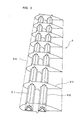
- Fig. 3 is a perspective view showing a framed structure of a wind-driven device blade of the vertical axis type wind power station according to the invention
- Fig. 6 is a perspective view of a wings-like board of the framed structure.
- the blade shown in Fig. 3 can be used as that of the vertical axis type wind power station of Fig. 1 , for example.
- the blade 3 has a shape of the wing section of an aeroplane, and its one face 3a is formed convex to elongate the streamlines whereas its other face 3b is formed flat to shorten the stream lines.
- the one face 3a should not be limited to the arrangement confronting the outside, as shown, but may also be arranged to confront the inside and to be in direction toward the axis.
- the blade 3 is formed of a framed structure, which is composed of: main supporting members 31 and 32 extending in the longitudinal direction of the blade; and a number of wings-like boards 33 fixed in inserting manner into those main supporting members 31 and 32; and a contouring sheet (or skin) 34 applied around the wings-like boards 33.
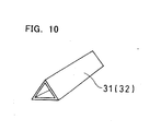
- the main supporting member 31 or 32 is formed of a hollow member of a triangular section and is either made of an extruded material of an aluminum alloy, as shown in Fig. 10 , or formed by folding an aluminum alloy sheet or of a joint structure of an aluminum alloy sheet.
- the member used in Fig. 3 is manufactured by rivet jointing a first plate folded in a triangular shape and a second plate formed flat.
- the two main supporting members 31 and 32 are arranged across the wings-like board 33.
- Three main supporting members can also be arranged according to the size of the blade 3.
- the aforementioned support members 12 and 13 are jointed to the main supporting members 31 and 32 by means of bolts or the like.
- the wings-like board 33 is prepared by pressing out an aluminum alloy sheet into the contour of the wings-like board. This pressing operation is done by using an NC machine. Therefore, the wings-like board 33 has a periphery fitted with approximate curves by a combination of straight lines. In another method, the wings-like board 33 is punched out with a so-shaped die.
- the wings-like board 33 is formed of cut holes 35 and 36, into which the main supporting members 31 and 32 are to be inserted, and projections 37 and 38, through which the skin 34 described later is to be inserted and positioned, and is formed of a plurality of seats 39 and 40, on which the skin 34 is to be stabilized, by folding them at 90 degrees with respect to the wings-like board 33.
- the projection 37 and the two seats 39 are arranged on the convex face side of the wings-like board 33, and the projection 38 and the three seats 40 are arranged on the flat face side of the wings-like board 33.
- the wings-like boards 33 are inserted at a predetermined interval onto the main supporting members 31 and 32. And, the main supporting members 31 and 32 and the wings-like board 33 are fixed by welding them at a plurality of portions. By fixing the two members, the framed structure is made strong, as shown in Fig. 3 .
- the skin 34 or the contouring sheet is made of a thin sheet of an aluminum alloy and is applied around the wings-like board 33.
- the skin 34 is so placed on the seats 39 and 40 of the wings-like board 33 as to receive the projections 37 and 38 of the wings-like board 33.
- the projections 37 and 38 are left as they are, after the skin 34 was applied.
- the projections 37 and 38 may be either cut off along the surface of the skin 34 or folded along the skin 34.
- the skin 34 is fixed on the seats 39 and 40 by means of rivets.
- Fig. 11 shows a process for applying the skin 34.
- the skin 34 is positioned by inserting its one side hole 34a onto the projection 38 of the flat face (or one face) of the wings-like board 33 and is extended along the wings-like board 33 by pulling the other end side of the skin 34.
- This pulling operation is carried out by pulling an extending tape member 60 adhered to the other end side of the skin 34. With this extending tape member 60, the skin 34 can be homogeneously pulled out without any wrinkle.
- the skin 34 is fixed on the seat 40 by means of rivets 62.
- a blind rivet is used as the rivet 62.
- a blind rivet assembly is inserted into the preformed through hole of the seat 40 and a pin 63 is pulled out. Then, the blind rivet bulges at its lower portion so that the pin 63 is pushed out to form the fixed state by the rivet 62, as shown.
- side of the flat face of seat40 Here, the other end side of the skin 34 has a generally L-shaped character. The other end side of the skin 34 is folded out in advance so that it can be made to mate the one end side flatly.
- the skin 34 is positioned by inserting the hole 34b of its other end side on the projection 37 on the convex face (or other face) of the wings-like board 33, as shown in Fig. 11(b) , and is extended along the remaining portion of the wings-like board 33 by pulling the other end side of the skin 34.
- This pulling operation is carried out by pulling the extending tape member 60 adhered to the other end side of the skin 34.
- the skin 34 can be homogeneously pulled out without any wrinkle.
- the mating portions 61 of the one end side and the other end side of the skin 34 are fixed by spot-welding them.
- the skin 34 is fixed on the seats 39 by means of the rivets 62.
- a blind rivet is used as the rivet 62.
- a blind rivet assembly is inserted into the preformed through hole of the seat 39 from the side of the skin 34 and the pin 63 is pulled out. Then, the blind rivet bulges at its lower portion so that the pin 63 is pushed out to form the fixed state by the rivet 62, as shown.
- the blade 3 formed by that process has a strength holding structure with the hollow main supporting members 31 and 32 of an aluminum alloy and has a shape holding structure with the wings-like boards 33 of an aluminum alloy. Moreover, the skin 34 can be positioned through the hole 34b of its other end side by the projection 37 so that it can be easily extended along the wings-like boards 33. Therefore, the contour of the blade 3 can be easily formed with the thin skin 34 of an aluminum alloy.
- the blade 3 can be finished light and strong as a whole. As a result, the blade 3 can be efficiently turned by the wind acting thereon.
- the number of blades 3 attached to the vertical axis type wind power station may be two or more.
- the blades 3 may be so concentrically arranged with a plurality of blades on the inner circumference side and a plurality of blades on the outer circumference side.
- the arrangement of the convex face of the blade 3 should not be limited to that toward the outer circumference, but the blade 3 may also have its flat face arranged toward the outer circumference.
- the blades 3 are light and strong, as described above, so that a proper number of blades 3 can be efficiently turned with the wind.
- Fig. 12 is a sectional view of the blade mounting structure.
- the main supporting members 31 and 32 are made of an extruded material having a triangular section, each side of which is arranged in parallel with the chord length.
- a mounting bracket 41 is a plate-shaped member having two generally convex holes for fitting the main supporting members 31 and 32 therein. Moreover, the mounting bracket 41 is so attached that its portion may extend through the skin 34 and project out toward the rotating post 2 and that its parallel face may be horizontal. Moreover, the mounting bracket 41 has a side 41a formed in its projecting portion in parallel with the chord length (as indicated by a single-dotted line in Fig. 12 ).
- a support member 42 is a pipe-shaped member or a plate-shaped member.
- a pipe having a slender elliptical shape may also be used to suppress the resistance of the wind.
- Bolts 43 are used to joint the mounting bracket 41 and the support member 42.
- the joint is made with the four bolts but may be made with at least two bolts 43.
- Pins 44 are used to position the mounting bracket 41 and the support member 42 thereby to position and joint the mounting bracket 41 and the support member 42.
- the pin joint is made with the two pins 44 but may be made with at least one pin 44.
- the mounting bracket 41 and the support member 42 are jointed with the two or more pins 44.
- the positioning joint may be made by using reamer bolts or convex-concave fittings in place of the pins.
- the mounting bracket 41 is provided at its projecting portion with the side 41a parallel to the chord length so that it can grasp the chord length direction of the blade 3 easily thereby to facilitate the adjustment of the mounting angle of the blade 3.
- the positioning can be ensured so that the mounting angle can eliminate the discrepancy and can keep the desired value.
- each side of the triangle of the section of the main supporting members 31 or 32 is arranged in parallel with the chord length, the chord length direction of the blade 3 can be grasped with respect to one side of the triangle so that the mounting angle of the blade can be adjusted without using the mounting bracket 41.
- the main supporting members 31 and 32 may have not only the triangular section but also other polygonal shapes. If these polygonal main supporting members have one side parallel to the chord length direction of the blade 3, it is possible to achieve effects like those of the case of the main supporting members having the triangular section.
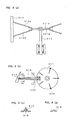
- Fig. 4(a) is a diagram showing a mode, in which the blades are so mounted on the support members with hinges or springs that they can be longitudinally inclined.
- Fig. 4(b) is a view taken in the direction of arrows (b) and (b) of Fig. 4(a) .
- a support member 275 is a member having a generally T-shaped section normal to the ground.
- a blade 273 is hinged in a rocking manner at its leading end portion 276. In the vicinity of the leading end portion on the side opposite to the leading end portion 276, moreover, the blade 273 is also so attached by a spring 274 as to be freely inclined longitudinally of the blade 273.
- the blade 273 can be freely inclined longitudinally of itself as a centrifugal force or wind pressure at a predetermined or higher level is generated at the blade 273 by a strong wind. Therefore, the centrifugal force or wind pressure at the predetermined or higher level can be reduced so that the blade is not subjected to any abrupt stress but is hardly broken.
- the blade 273 can be freely rocked longitudinally and transversely of itself, if the leading end portion 276 and the blade 273 are jointed with a pin, although not shown.
- Fig. 4(c) the support member 275 of Fig. 4(a) is turned by 90 degrees on its axis, and the blade 273 is so jointed with a hinge and a spring like Fig. 4(a) as may be freely inclined in the transverse direction.
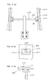
- Fig. 8(a) is a diagram showing the vicinity of the upper portion of a rotating post 312 of the vertical axis type wind power station.
- the rotating post 312 two upper and lower discs 311a and 311b mounted on the upper portion of the rotating post 312 are provided with a transversely upward upper support member 314a and a transversely downward lower support member 314b, respectively.
- a blade 313 is attached at its longitudinally upper and lower portions to the leading ends of the upper support member 314a and the lower support member 314b.
- the discs 311a and 311b are fixed on and supported by the rotating post 312 at their central portions by means of bolts or the like.
- the discs 311a and 311b for carrying the first support member 314a and the lower support member 314b are slitted at their edge portions so that they can be folded to easily mount the individual support members. However, the portions 316 near the circumference in the slits at portions left unfolded are fixed by welding them.
- Fig. 8(b) is a top plan view of Fig. 8(a);
- Fig. 8(c) is a view taken in the direction of arrows (c) and (c) of Fig. 8(b);
- Fig. 8(d) is a view taken in the direction of arrows (d) and (d) of Fig. 8(b) .
- the upper support member 314a and the lower support member 314b are generally formed into such an angle section as has a smaller modulus of section toward the leading end and have substantial triangle sections.
- the upper support member 314a and the lower support member 314b are reinforced to stand the force (i.e., the force by the wind pressure received by the blade 313) in the circumferential direction of the discs 311a and 311b by a plate member 315, which is mounted at its one side face in the radial direction of the discs 311a and 311b and fixed at its other side face on the angle back sides of the upper support member 314a and the lower support member 314b on the disc side end.
- the blade 313 can be stably supported to prevent troubles while it is being turned.
- the structure may be modified such that the blades adjoining in the circumferential direction are connected to each other.
- the blades may be connected to each other by a plate-shaped member, or the joint portions of the upper support members 314a and the blades 313 may be jointed by means of wires.
- the wind power station can be lightened if the individual blades are made of aluminum.
- Fig. 13 is a schematic diagram illustrating a construction of the light-weight vertical axis type wind power station, which can suppress the bending moment sufficiently.
- Fig. 14 is a perspective view illustrating the vertical axis type wind power station of Fig. 13 .
- the vertical axis type wind power station 1 is constructed to include: a rotating post 2 erected upright; a plurality of longitudinal blades 9 arranged in the circumferential direction of the rotating post 2; rotors 18 and 20 provided at the leading end of the rotating post 2; two upper and lower arms 4 and 6 attached obliquely upward or downward to the rotors 18 and 20, for supporting the two longitudinally upper and lower portions of the blade 9; and two intermediate arms 11 and 14 attached to the rotors 18 and 20 or the upper and lower arms 4 and 6, for supporting the two intermediate portions of the blade 9.
- the blade 9 is similar to the blade 3 shown in Fig. 3 .
- the tube-shaped rotor 20 is inserted onto and jointed to the leading end of the rotating post 2.
- the tube-shaped rotor 20 may be formed into any of a circular tube, a polygonal tube and a framed structure but is a circular tube in this case.
- the tube-shaped rotor 20 is made of a light, strong aluminum alloy or the like so that the vertical axis type wind power station 1 is made light-weight.
- the tube-shaped rotor 20 has its axial center of gravity located at c/2 or the center of length c of the blade 9 and its circumferential center of gravity located at the same axis as that of the rotating post 2. Therefore, the vertical axis type wind power station 1 has its center of gravity located at that of the tube-shaped rotor 20. Moreover, the tube-shaped rotor 20 is shaped to have vertical and transverse symmetries with respect to the center of gravity.
- the rotating post 2 is rotatably supported by a housing 22 through a bearing 21a, a bearing 21 and a thrust bearing 30 so that the tube-shaped rotor 20 rotates together with the rotating post 2.
- the bending stress against a transverse load such as a cross wind can be reduced by minimizing the distance m between the center of gravity of the tube-shaped rotor 20 and the bearing 21a.
- the upper arm 4 is arranged obliquely downward with respect to the tube-shaped rotor 20 and has its first end portion 3 attached to the upper portion of the tube-shaped rotor 20 and its upper joint portion 7 jointed to a main supporting member 19 of the blade 9 so that it supports the longitudinally upper portion of the blade 9.
- the lower arm 6 is arranged obliquely upward with respect to the tube-shaped rotor 20 and has its second end portion 5 attached to the lower portion of the tube-shaped rotor 20 and its lower joint portion 8 jointed to the main supporting member 19 of the blade 9 so that it supports the longitudinally lower portion of the blade 9.
- the upper arm 4 and the lower arm 6 are attached to the vicinities of the center of gravity of the vertical axis type wind power station, that is, to the upper portion and the lower portion of the tube-shaped rotor 20 so that they balance the bending moments generated at the upper joint portion 7 and the lower joint portion 8.
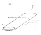
- the upper arm 4 and the lower arm 6 are formed into a hollow tube having a flattened section, as shown in Fig. 15 , and are made of a light-weight, strong aluminum alloy or the like. Therefore, the upper and lower arms 4 and 6 can reduce the weight of the vertical axis type wind power station 1, and their sectional shape can reduce the windage loss and the inertia.
- the first intermediate arm 11 is a main arm having a third end portion 10 attached to the upper portion of the tube-shaped rotor 20 and is horizontally arranged to have a first intermediate joint portion 12 jointed to the main supporting member 19 of the blade 9, so that it supports the intermediate upper portion of the blade 9.
- the second intermediate arm 14 is a main arm having a fourth end portion 13 attached to the lower portion of the tube-shaped rotor 20 and is horizontally arranged to have a second intermediate joint portion 15 jointed to the main supporting member 19 of the blade 9, so that it supports the intermediate lower portion of the blade 9.
- the first intermediate arm 11 and the second intermediate arm 14 are attached to the center of gravity of the vertical axis type wind power station, that is, in vertical symmetry with respect to the center of gravity of the tube-shaped rotor 20 so that they balance the bending moments generated at the first intermediate joint portion 12 and the second intermediate joint portion 15.
- the first intermediate arm 11 and the second intermediate arm 14 are formed into a hollow tube having a flattened section, like the upper arm 4 and the lower arm 6 shown in Fig. 15 , but are the main arms for supporting the blade 9 firmly so that they are made thicker than the upper arm 4 and the lower arm 6.
- the first intermediate arm 11 and the second intermediate arm 14 are also made of a light-weight, strong aluminum alloy or the like. Therefore, the first and second intermediate arms 11 and 14 can reduce the weight of the vertical axis type wind power station 1, and their sectional shape can reduce the windage loss and the inertia.
- the portions of the tube-shaped rotor 20, to which the two intermediate arms and the upper and lower arms are attached are made different.
- the first intermediate arm 11 and the upper arm 4 could be attached to the common portion of the tube-shaped rotor 20 and that the second intermediate arm 14 and the lower arm 6 could also be attached to the common portion of the tube-shaped rotor 20.
- the housing 22 is provided with a base 23, which is fixed on the not-shown foundation by suitable fixing means. Moreover, a generator 25 is connected to the lower portion of the rotating post 2 through a suitable gear mechanism 24. In another construction, the generator 25 may be connected directly to the rotating post 2.
- the blades 9 rotate, as they receive the cross wind, in the circumferential direction of the rotating post 2, so that the tube-shaped rotor 20 accordingly rotates.
- the turning force of the tube-shaped rotor 20 acts on the rotating post 2, which is vertically supported by the bearings 21 and 21a and which is horizontally supported by the thrust bearing 30 for bearing the axial load.
- the rotating post 2 rotates to transmit its turning force to the generator 25 through the gear mechanism 24 below the rotating post 2.
- the vertical axis type wind power station generates the electric power.
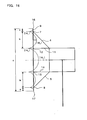
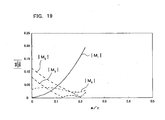
- the longitudinal length of the blade is designated by c; the distance from the upper end 16 of the blade to the upper joint portion 7 is designated by a; and the distance from the upper joint portion 7 to the first intermediate joint portion 12 is designated by b.
- the distance from the lower end 17 of the blade to the lower joint portion 8 is designated by a, and the distance from the lower joint portion 8 to the second intermediate joint portion 15 is designated by b.
- a bending moment to be generated at the upper joint portion 7 and the lower joint portion 8 is designated by M 1 ; a bending moment to be generated at the first intermediate joint portion 12 and the second intermediate joint portion 15 is designated by M 2 ; a bending moment to be generated at a central portion of the blade is designated by M 3 ; and a bending moment to be generated at the distance b is designated by M 4 .
- contour lines as drawn by the absolute values
- the results are presented in Fig. 17 .
- the ordinate indicates b/c
- the blades 9 are supported at the upper and lower points and at the two central points by the two upper and lower arms 4 and 6 and the two intermediate arms 11 and 14, which are attached to the vicinities of the center of gravity of the tube-shaped rotor 20, and the positions of the supporting points of the blades 9 are balanced vertically symmetrically with respect to the center of gravity of the tube-shaped rotor 20. Therefore, it is possible to minimize the bending moments, which are generated at the blades 9 by the centrifugal force. Especially, the distances between the individual supporting points can be optimized, as described above, to minimize the bending moments reliably. Moreover, the arms are made light and shaped to have the horizontally flat section so that the resistance to be borne by the arms can be reduced to reduce the windage loss and to lighten the vertical axis type wind power station.
- the vertical axis type wind power station 1 may be constructed, as shown in Fig. 20 .
- the first intermediate arm 11 and the second intermediate arm 14 are obliquely arranged.
- the third end portion 10 of the first intermediate arm 11 is jointed to the first end portion 3 or the joint portion of the tube-shaped rotor 20 and the upper arm 4, and the fourth end portion 13 of the second intermediate arm 14 is jointed to the second end portion 5 or the joint portion of the tube-shaped rotor 20 and the lower arm 6.
- the two intermediate arms and the upper and lower arms are attached at the common positions to the tube-shaped rotor 20.
- the two intermediate arms and the upper and lower arms could be attached to different portions.
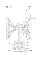
- the vertical axis type wind power station 1 may also be constructed, as shown in Fig. 21 .
- the first intermediate arm 11 and the second intermediate arm 14 are horizontally arranged, but the third end portion 10 of the first intermediate arm 11 is jointed to the upper arm 4, and the fourth end portion 13 of the second intermediate arm 14 is jointed to the lower arm 6. As a result, it is possible to shorten the two intermediate arms.
- first intermediate arm 11 and the second intermediate arm 14 should not be limited to the horizontal arrangement but may be obliquely arranged.
- the construction of the vertical axis type wind power station 200 is different from the vertical axis type wind power station 1 in that a disc 18 is disposed in place of the tube-shaped rotor 20 at the upper portion of the rotating post 2.
- the upper arm 4 is arranged obliquely downward with respect to the disc 18, and has its first end portion 3 attached to the upward folded portion of the disc 18 and its upper joint portion 7 jointed to the main supporting member 19 of the blade 9 thereby to support the longitudinally upper portion of the blade 9.
- the lower arm 6 is arranged obliquely upward with respect to the disc 18, and has its second end portion 5 attached to the downward folded portion of the disc 18 and its lower joint portion 8 jointed to the main supporting member 19 of the blade 9 thereby to support the longitudinally lower portion of the blade 9.
- the first intermediate arm 11 has its third end portion 10 attached to the upward folded portion of the disc 18 and is obliquely arranged to have its first intermediate joint portion 12 jointed to the main supporting member 19 of the blade 9 thereby to support the intermediate upper portion of the blade 9.
- the second intermediate arm 14 has its fourth end portion 13 attached to the downward folded portion of the disc 18 and is obliquely arranged to have its second intermediate joint portion 15 jointed to the main supporting member 19 of the blade 9 thereby to support the intermediate lower portion of the blade 9.
- the vertical axis type wind power station 200 may also be constructed, as shown in Fig. 23 .
- the first intermediate arm 11 and the second intermediate arm 14 are horizontally arranged.
- the first intermediate arm 11 has its third end portion 10 jointed to the upper arm 14, and the second intermediate arm 14 has its fourth end portion 13 jointed to the lower arm 6.
- the two intermediate arms can be shortened.
- first intermediate arm 11 and the second intermediate arm 14 should not be limited to the horizontal arrangement but may also be obliquely arranged.
- the bending moment due to the transverse load can be reduced to zero by locating the position of the bearing 21a adjacent to the tube-shaped rotor 20, at the axial center of gravity.
- the two intermediate arms 11 and 14 are grasped as the main arms for supporting the blade 9, but the upper and lower arms 4 and 6 may also be the main arms.
- the upper and lower arms 4 and 6 may be made thicker than the two intermediate arms 11 and 14 thereby to support the blade 9 firmly.
- the longitudinal blades may take a double structure, which is composed of a plurality of inner circumference blades arranged in the inner circumference of the rotating post and outer circumference blades connected to the inner circumference blades and arranged in the outer circumference.
- the four arms for supporting the inner circumference blades are arranged to minimize the bending moment due to the centrifugal force
- the four arms extending from the inner circumference blades for connect/support the outer circumference blades are arranged to minimize the bending moment due to the centrifugal force, so that the vertical axis type wind power station can have a lift enhanced for the wind.
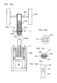
- Fig. 7 is a diagram showing a rotating post height adjusting mechanism and a rotating post supporting mechanism.
- the rotating post height adjusting mechanism 300 is constructed to include: a tube-shaped rotating post 301 provided at its upper portion with support members 305 having blades 303 attached thereto and at its lower portion with two portions having two cuts of the same shape; a rod-shaped shaft 302 provided at its upper portion with a plurality of diametrically through holes and at its lower portion with a partial notch; and a fixing support pin 304 for fixing and supporting the rotating post 301 and the rotating post 302.
- the rotating post 302 is provided with the through holes 302a so that the height of the rotating post 301 can be adjusted by changing the inserted position of the fixing support pin 304 in the through hole 302a and by fixing and supporting the rotating post 301 and the rotating post 302.
- the rotating post 302 has its lower portion cut off to be fitted in a rotating post supporting member 306, so that it can be removed.
- the structure should not be limited to the shape shown in Fig. 7(b) , if it can fit the rotating post 302 in its supporting member 306.
- the structure may be formed into a polygonal shape such as a triangle or square or may be splined.
- Fig. 7(c) is a diagram presenting a section of the rotating post at the portion of the fixing support pin 304.
- Fig. 9 is a diagram showing one example of a mode for suppressing the turning load of the rotating post.
- a radial ball bearing 602 In a tube 601 positioned upward, there are arranged a radial ball bearing 602, a thrust ball bearing 603, a rotating post 604 and a touchdown ball bearing 605.
- the radial ball bearing 602 bears the load perpendicular to the axis of rotation and is fixed in the upper portion of the inner wall of the tube 601 thereby to support the rotating post 604 rotatably.
- the thrust ball bearing 603 bears the load on the axis of rotation, and is composed of: a ring-shaped plate member 603a on one side; a ring-shaped plate member 603b on the other side; and a plurality of balls 603c.
- the one-side ring-shaped plate member 603a is fixed normal to the tube 601 in the lower portion of the inside of the tube 601, and is arranged at a clearance from the inner wall of the tube 601.
- the other-side ring-shaped plate member 603b is fixed normal to the rotating post 604, and is arranged at a clearance from the outer wall of the rotating post 604.
- the balls 603c are so held between the plate member 603a and the plate member 603b as can move freely along the not-shown circumferential grooves formed in those plate members.
- the thrust ball bearing 603 supports the rotating post 604 rotatably.
- the rotating post 604 is rotatably supported at the central portion of the tube 601 by the radial ball bearing 602 and the thrust ball bearing 603.
- the rotating post 604 is so stepped in section at its lower portion as to fit the ring-shaped plate of the upper portion of the thrust ball bearing 603.
- This touchdown ball bearing 605 is mounted in the inner wall of the tube 601 above and near the thrust ball bearing 603 and at a clearance from the rotating post 604.
- the thrust ball bearing 603 cannot bear the transverse load. Therefore, the load at the time when the rotating post 604 rocks transversely is concentrated at the radial ball bearing 602 disposed above, so that the structure is weak against the transverse load. Therefore, the touchdown ball bearing 605 is disposed below the tube 601, to bear the transverse load resulting from the rocking motions of the rotating post 604 thereby to support the rotating post 604 rotatably till the rotating post 604 stabilizes in its turning motions. And, the rotating post 604 leaves the touchdown ball bearing 605 as its rotation starts to stabilize.
- the transverse load when the rotating post 604 rocks can be borne by the touchdown ball bearing 605 in place of the thrust ball bearing 603 incompetent therefor.
- the rotating post 604 can turn stably.
- a radial roller bearing may also be used in place of the radial ball bearing 602.
- this radial ball bearing 602 may also be fixed at the midway portion of the tube 601.
- the thrust ball bearing 603 may also be replaced by a thrust roller bearing or a thrust magnetic bearing.
- the touchdown ball bearing 605 may also be replaced by a touchdown roller bearing.
- the touchdown ball bearing 605 may also be disposed below and near the thrust ball bearing 603.
- Fig. 5(a) is a diagram showing one example of the mode for leaking the electricity from the rotating post.
- An electric brush 281 for leaking the electricity from the rotating post 282 is so disposed at a midway portion of the outer tube 284 of bearings 285 that its leading end portion may contact with the rotating post 282.
- the side portion of the electric brush 281, as opposite to the side contacting with the rotating post 282, is earthed to the ground.
- Fig. 5(b) is a diagram showing another example of the mode for leaking the electricity from the rotating post. Insulating members 286 are sandwiched between the rotating post 282 and the outer tube 284 of the bearings 285 for supporting the rotating post 282.
- Fig. 25 is a sectional view of one example of the peripheral portion of the tube-shaped rotating post in the vertical axis type wind power station of Fig. 24 .
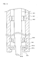
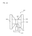
- the vertical axis type wind power station 400 is provided, as shown in Fig. 24 and Fig. 25 , with: a rotating post 402 erected upright; two longitudinal blades 403 attached in the circumferential direction of the rotating post 402; a tube-shaped rotating member 404 attached to the rotating post 402 through disc-shaped flanges 405 and 406; support members 407 connecting the tube-shaped rotating member 404 and the individual blades 403; a tube 408 supporting the rotating post 402 rotatably through bearings 409, 410 and 411; a generator device 412 arranged below the rotating post 402; and a base 413 for supporting the station as a whole.
- the rotating post 402 is arranged at the center of the vertical axis type wind power station 401 thereby to transmit the turning force of the rotating member 404 to the generator device 412.
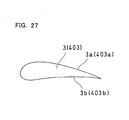
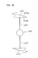
- the blade 403 is shaped to have a section of or like the wing of an aeroplane, as shown in Fig. 27 . As shown in Fig. 28 , moreover, the blades 403 are arranged symmetrically with respect to the tube-shaped rotating member 404, as shown in Fig. 28 , when the vertical axis type wind power station 400 is seen downward.
- the number of the blades 403 is exemplified by two in this mode of embodiment, but may be three or more.
- one face 403a and the other face 403b of one of the two blades 403 shown in Fig. 28 may be reversed.
- the tube-shaped rotating member 404 is made of a tube having a circular section and is provided at its central portion with the plate-shaped horizontal flange 405. Moreover, the tube-shaped rotating member 404, the flange 405 and the blades 3 are so arranged that their individual vertical center lines may be aligned (as referred to a single-dotted line in Fig. 25 ). As shown in Fig. 25 , more specifically, the tube-shaped rotating member 404, the flange 405 and the blades 403 are arranged with the center line, which is located at a distance of L/2 from one end of the tube-shaped rotating member 404 having a length L.
- the tube-shaped rotating member 404 may be a tube having a polygonal section, a tube having a framed structure or a tube having a vertical spindle shape.
- the flange 406 is provided for fixing the flange 405 reliably on the rotating post 2.
- the support members 407 are provided for fixing and supporting the blades 403 and the tube-shaped rotating member 404, and are arranged vertically symmetrically with respect to the single-dotted line in Fig. 25 .
- the support members 407 may be a rod or pipe shape or a plate shape.
- the pipe In the case of the pipe shape, the pipe may be pushed in the sectional direction to have an elliptical section and may be attached in a direction to suppress the air resistance.
- the construction may be modified to balance the strength and the light weight by combining thin support members and thick support members.
- the radial ball bearings 409 and 410 In the upright tube 408, there are arranged the radial ball bearings 409 and 410, the rotating post 402 and the thrust ball bearing 411.
- the radial ball bearings 409 and 410 bear the load in the direction perpendicular to the direction of the rotating post, and are fixed in the upper and midway portions on the inner wall of the tube 408 thereby to support the rotating post 402 rotatably.
- the radial ball bearing 410 may be replaced by the so-called “touchdown ball bearing” for bearing the load of the rotating post 402 temporarily when the rotating post 402 rocks transversely.
- the thrust ball bearing 411 bears the load in the longitudinal direction of the rotating post 402, and is arranged on the inner wall of the tube 408 below and near the radial ball bearing 410.
- the radial ball bearings 409 and 410 may also be replaced by radial roller bearings.
- the thrust ball bearing 411 may also be replaced by a thrust roller bearing or a thrust magnetic bearing.
- the touchdown ball bearing may also be replaced by a touchdown roller bearing.
- the touchdown ball bearing may also be disposed below and near the thrust ball bearing 411.
- the blades 403 transmit, when they receive the wind, the power of the wind force through the support members 407 to the tube-shaped rotating member 404.
- the support members 407 and the blades 403 attached to the tube-shaped rotating member 404 are arranged to balance the center of gravity on the single-dotted line in Fig. 25 , and the distance between the center of gravity of the tube-shaped rotating member 404 and the disposition of the bearings is short, so that the tube-shaped rotating member 404 rotates while being well balanced in the circumferential direction.
- the tube-shaped rotating member 404 transmits the turning force to the rotating post 402 through the flanges 405 and 406, which are disposed at the center in the tube-shaped rotating member 404.
- the rotating post 402 rotates while being rotatably supported by the bearings 409, 410 and 411 in the tube 408, thereby to transmits the turning force to the generator device 412. As a result, the power is generated by the generator device 412.
- the support members 407 and the blades 403 attached to the tube-shaped rotating member 404 are arranged to balance the center of gravity with respect to the single-dotted line in Fig. 25 , and the distance between the center of gravity of the tube-shaped rotating member 404 and the disposition of the bearings is short, so that the tube-shaped rotating member 404 rotates while being well balanced in the circumferential direction and so that the horizontal bending moment due to the cross wind can be reduced on the rotating post 402.
- the rotating post need not be thickened so that the diameters of the bearings can be reduced. Therefore, it is possible to provide a small-sized light-weight vertical axis type wind power station, which can suppress the mechanical loss thereby to make the power generation efficient.
- Fig. 26 is a sectional view of another example of a tube-shaped rotating member in the vertical axis type wind power station of Fig. 24 .
- the description may be omitted on the portions similar to those of the vertical axis type wind power station 400.
- the vertical axis type wind power station having the tube-shaped rotating member 404 of Fig. 26 has a construction substantially similar to that of the vertical axis type wind power station 400, excepting that the tube-shaped rotating member 404, the radial ball bearing 9 and the blades 403 are arranged to have their individual vertical center lines aligned (as referred to a single-dotted line in Fig. 26 ). As shown in Fig. 26 , more specifically, the tube-shaped rotating member 404, the radial ball bearing 409 and the blades 403 are arranged on the center line, which is located at the distance of L/2 from one end of the tube-shaped rotating member 404 having the length L.
- the blades 403 transmit, when they receive the wind, the power of the wind force through the support members 407 to the tube-shaped rotating member 404.
- the support members 407 and the blades 403 attached to the tube-shaped rotating member 404 are arranged to balance the center of gravity with respect to the single-dotted line in Fig. 26 , and the distance between the center of gravity of the tube-shaped rotating member 404 and the disposition of the bearings is short, so that the tube-shaped rotating member 404 rotates while being well balanced in the circumferential direction.
- the tube-shaped rotating member 404 transmits the turning force to the rotating post 2 through the flanges 405 and 406, which are disposed at the center in the tube-shaped rotating member 404.
- the rotating post 2 rotates while being rotatably supported by the bearings 409, 410 and 411 in the tube 408, thereby to transmits the turning force to the generator device 412. As a result, the power is generated by the generator device 412.
- the wind-driven device 511 is provided with a rotating shaft 512, blades 513, a rotating plate 514 and a wind collecting member 515.
- This wind collecting member 515 is formed into a shape of a hollow cone having a tip cut off.
- a (not-shown) hole for inserting the rotating shaft 512 thereinto.
- the rotating shaft 512 is rotatably inserted into that hole.
- the disc-shaped rotating plate 514 is so arranged in the vicinity of the upper end portion of the rotating shaft 512 that it may rotate with the rotating shaft 512. Moreover, the not-shown power generator is connected to the rotating shaft 512 so that it generates the electric power with the turning drive force of the rotating shaft 512.
- the rotating plate 514 is provided with upper support members 513a and lower support members 513b, which are fixed to the upper portions and the lower portions of the blades 513, respectively.
- These blades 513 are equivalently arranged on the rotating plate 514 through the upper support members 513a and the lower support members 513b.
- the blades 513 are extended perpendicularly of the rotating direction and are curved to receive a wind A easily. This wind A forces the curved portions of the blades 513 to turn the blades 513 thereby to rotate the rotating shaft 512. Moreover, the wind A blowing below the blades 513 is turned upward by the skirted side face of the wind collecting member 515 thereby to turn the blades 513.
- the structure for mounting the wind-driven device according to this mode is provided with a fixing pole 501, a connecting member 502, joints 503 and a fan fixing member 504.
- This fan fixing member 504 is disposed at the upper end portion of the fixing pole 501. Moreover, the fan fixing member 504 is provided with the not-shown bearing, through which the rotating shaft 512 of the wind-driven device 511 is rotatably supported by the fan fixing member 504. As a result, the wind-driven device 511 is supported at the upper end portion of the fixing pole 501.
- the power generator connected to the rotating shaft 512 may be disposed in the fan fixing member 504.
- the fixing pole 501 is fixed on the building 510 near the upper end portion having the wind-driven device 511 by the connecting member 502.
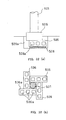
- This connecting member 502 is described in the following. As shown in Fig. 31 , the connecting member 502 is provided with a U-shaped fixture 521, a nut 522, a bolt 523, neoprene rubber members 525a and 525b, and a C-shaped fixture 524.
- the U-shaped fixture 521 is provided with two joint portions, which have (not-shown) holes and which are disposed in the open portion of the U-shape. These joint portions are held in contact with the wall 510a of the building 510 of the U-shaped fixture 521 while fitting the fixing pole 501 in the U-shaped recess.
- the neoprene rubber member 525a of foamed rubber is wound on the fixing pole 501.
- the fixing pole 501 can be tightly fixed on the wall 510a by the U-shaped fixture 521 so that the fixed portion can be made stronger.
- the neoprene rubber member 525b and the C-shaped fixture 524 are arranged Across the wall 510a of the building 510 and at a position opposite to the U-shaped fixture 521.
- the neoprene rubber member 525b is sandwiched between the wall 510a and the C-shaped fixture 524.
- there are formed (not-shown) holes In the wall 510a of the building 510 and the vicinities of the two ends of the neoprene rubber member 525b and the C-shaped fixture 524, there are formed (not-shown) holes.
- the neoprene rubber member 525b and the C-shaped fixture 524 are arranged with those individual holes being registered with each other.
- the bolts 523 are inserted from the side of the U-shaped fixture 521 into the holes, and the nuts 522 are fastened from the side opposite to the U-shaped fixture 521, thereby to fix the U-shaped fixture 521, the neoprene rubber member 525b and the C-shaped fixture 524 on the wall 510a.
- a washer 523a and a spring washer 523b are sandwiched individually between the bolt 523 and the U-shaped fixture 521 and between the nut 522 and the C-shaped fixture 524.
- the neoprene rubber member 525b eliminates the clearance between the C-shaped fixture 524 and the wall 510a thereby to fix the C-shaped fixture 524 firmly on the wall 510a.
- the fixture 524 is shaped in the letter "C" to enclose above and below the nut 522. With this C-shaped fixture 524, the fastening pressure of the nut 522 is dispersed but not concentrated at one portion thereby to improve the durability.
- a waterproof sealant is applied to the inner walls of the holes formed in the wall 510a and to the surfaces of the nuts 522, the bolts 523 and the individual washers 523a and 523b. As a result, the wall 510a can be prevented from being soaked with the water of rain.
- the connecting member 502 is disposed at a position above the central portion of the fixing pole 501.
- the distance from the disposition of the connecting member 502 to the lower end portion of the fixing pole 501 is longer than the distance from the disposition of the connecting member 502 to the upper end portion of the fixing pole 501.
- the fixing pole 501 is buried at its lower end portion in the ground 509.
- a hole 509a having a depth of about 30 cm is formed in the ground 509.
- the hole 509a is paved on its bottom with gravel 508 as thick as about 10 cm.
- the (not-shown) cement is poured over the gravel 508 thereby to fix the gravel 508.
- Blocks 506 are laid in juxtaposition over the poured cement before the cement solidifies.
- the block 506 has a rectangular parallelepiped shape and has holes 506a extending perpendicularly to the longitudinal direction.
- the direction, in which the holes 506a are perpendicular to the ground 509 is determined as the longitudinal direction of the block 506.
- Cement is then poured over the juxtaposed blocks 506 to erect the fixing pole 501 upright.
- This fixing pole 501 erected is enclosed and fixed by the four blocks 506 placed in the longitudinal direction to form a swastika pattern.
- cement is poured into the holes 506a of the four blocks 506 of the swastika pattern.
- the hole 509a is buried with the soil or the like to fix the fixing pole 501 in the ground 509.
- the fixing pole 501 is formed into one tube-shaped rod by connecting a plurality of pipes 501a, 501b, - - -, and so on removably.
- the pipes 501a and 501b are tubes, each of which is reduced at its one end to have a slightly smaller diameter.
- the pipes 501a and 501b are connected by fitting the diametrically reduced end of the pipe 501a in the unreduced end of the pipe 501b.
- the joint 503 covers and fixes the connected portion of the pipes 501a and 501b.
- the joint 503 has a hollow tube-shaped fixture, which can enclose the pipes 501a and 501b (or the fixing pole 501). Moreover, the tube-shaped fixture is partially cut off and is provided at the cut portion with two joint members, which have (not-shown) holes and which are separated but can mate each other. By bringing the two joint members away from each other, the cut portion is opened so that the pipes 501a and 501b can be fitted in the hollow tube-shaped fixture of the joint 503.
- the hole 509a is formed in the ground 509, and the fixing pole 501 is fixed upright in the ground 509, as has been described hereinbefore.
- the fixing pole 501 is fixed at a region over its central portion on the building 510 by the connecting member 502.
- the fan fixing member 504 having the bearings is arranged at the upper end of the fixing pole 501.
- the wind-driven device 511 is arranged on the fan fixing member 504 so that its rotating shaft 512 may be rotatably supported through the bearings of the fan fixing member 504.
- the connecting position between the fixing pole 501 and the building 510 is disposed at a position above the central portion of the fixing pole 501.
- the distance from the connecting position to the lower end portion of the fixing pole 501 is longer than the distance from the connecting position to the upper end portion of the fixing pole 501.
- the strong force is applied to the wind-driven device 511 by a strong wind if the connecting position is considered as a fulcrum, therefore, it is not applied from a relation of the balance of forces to the lower end portion of the fixing pole 501, as fixed in the ground 509.
- the fixing pole 501 is formed by connecting the pipes 501a, 501b, - - -, and so on removably so that it can be easily transported.
- the wind-driven device 511 is fixed on the building 510 of the reinforced concrete.
- the wind-driven device 511 may also be fixed on a wooden house.
- the fixing pole 501 is fixed on a wooden column 520 by a connecting member 505 having a clamping fixture 526.
- This clamping fixture 526 is a U-shaped fixture having a width substantially equal to that of the wooden column 520, and has joint portions for clamping the column 520.
- the clamping fixture 526 and the column 520 have not-shown holes, and the clamping fixture 526 is arranged to register those holes.
- the clamping fixture 526 fits the fixing pole 501 in its U-shaped recessed portion and clamps the column 520 tightly.
- the neoprene rubber member 525a is wound on the portion, in which the fixing pole 501 contacts with the clamping fixture 526 and the column 520.
- the bolts 523 are inserted from one side into the holes, and the nuts 522 are fastened from the other side thereby to fix the fixing pole 501 on the column 520.
- the washer 523a and the spring washer 523b are sandwiched individually between the bolt 523 and the clamping fixture 526 and between the nut 522 and the clamping fixture 526.
- a waterproof sealant is applied to the inner walls of the holes formed in the column 520 and to the surfaces of the bolts 523 and the individual washers 523a and 523b. As a result, the column 520 can be prevented from being soaked with the water.
- a windbreak wind power plant 610 is provided with a plurality of vertical axis type wind power stations 601 at a predetermined position of a shoreline, as schematically shown in Fig. 35 .
- the foregoing vertical axis type wind power station or wind-driven device can be used as those vertical axis type wind power stations 601.
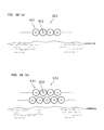
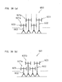
- Fig. 36 presents diagrams showing examples of the installation of the windbreak wind power plant.
- Fig. 36(a) is a schematic diagram showing the case, in which the vertical axis type wind power stations are arranged in only one row on the ground along the shoreline
- Fig. 36(b) is a schematic diagram showing the case, in which the vertical axis type wind power stations of a second row are arranged on the land side between the row of Fig. 36(a) .
- the inner circle portions indicate center shafts 602
- the outer circles indicate the loci of turning motions of blades 603.
- the blades 603 have a sectional shape of the wing of an aeroplane.
- the vertical axis type wind power stations 601 are arranged at an equal interval on one row along the shoreline.
- the individual vertical axis type wind power stations 601 may be so arranged at a distance two times or more of the distance (or the radius of gyration) from the centers of the rotating shafts 602 to the outermost portions of the blades 603 that the individual blades may be prevented from contacting with each other.
- the vertical axis type wind power stations 601 used have the longitudinal blades 603. Therefore, the individual vertical axis type wind power stations 601 can be disposed close to each other so that an effective windbreak can be made while generating the electric power.
- a windbreak wind power plant 630 of Fig. 36(b) the vertical axis type wind power stations of the second row are so disposed on the land side of the windbreak wind power plants 620 of Fig. 36(a) that their adjoining vertical axis type wind power stations are equidistantly arranged.
- the vertical axis type wind power stations 601 used have the longitudinal blades so that their individual ones can be disposed close to each other. Therefore, it is possible to perform a more efficient windbreak than that of the plant shown in Fig. 36(a) while generating the electric power simultaneously.
- the vertical axis type wind power stations 601 are arrayed in the first and second rows.
- the invention should not be limited to those arrays, but the windbreak wind power plant may have the vertical axis type wind power stations 601 arrayed in three or more rows.
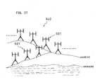
- FIG. 37 Another example of the windbreak wind power plant is shown in Fig. 37 . Even when the wind power plant is disposed along the ridgeline near the shoreline, as shown in Fig. 37 , the windbreak can also be efficiently performed while generating the electric power simultaneously.
- FIG. 38 presents schematic diagrams showing windbreak wind power plants, in which the blades of the individual vertical axis type wind power stations have different height positions.
- Fig. 38(a) is a side elevation showing the arrangement, in which the loci of turning motions of the blades overlap just at one point when the windbreak wind power plant is viewed from above
- Fig. 38(b) is a side elevation showing the arrangement, in which the loci of turning motions of the blades overlap when the windbreak wind power plant is viewed from above.
- the individual vertical axis type wind power stations 601 are arranged in such one row that the turning locus of the blades 603 arrayed at an upper stage in the vertical axis type wind power stations 601a and the turning locus of the blades 603 arrayed at a lower stage in the vertical axis type wind power stations 601b may overlap (as referred to broken lines of Fig. 38(a) ) when the windbreak wind power plant 650 is viewed from above.
- the individual vertical axis type wind power stations 601 are so closely arranged in one row that the turning locus of the blades 603 arrayed at an upper stage in the vertical axis type wind power stations 651a and the turning locus of the blades 603 arrayed at a lower stage in the vertical axis type wind power stations 601b may overlap when the windbreak wind power plant 651 is viewed from above.
- the upper and lower winds can be more efficiently caught than the windbreak wind power plant 650 shown in Fig. 38(a) , to perform the efficient windbreak and to generate the electric power.
- Figs. 38(a) and 38(b) show the examples, in which the vertical axis type wind power stations are arranged in one row.
- the invention should not be limited thereto but may be modified into an arrangement of two or more rows.
- the blades 603 are positioned at the two upper and lower stages of the vertical axis type wind power stations 601a and 601b.
- the arrangement may also have three or more stages.
- the windbreak wind power plant may combine the arrangements of Fig. 38(a) and Fig. 38(b) .
- the windbreak wind power plant may also have the vertical axis type wind power stations 601 of three or more rows.
- the invention can provide a wind power station which is made efficient by utilizing the natural energy such as a wind. Therefore, the invention can be expected to serve as an aid for solving the environmental problems.
Landscapes
- Engineering & Computer Science (AREA)
- Life Sciences & Earth Sciences (AREA)
- Sustainable Development (AREA)
- Sustainable Energy (AREA)
- Chemical & Material Sciences (AREA)
- Combustion & Propulsion (AREA)
- Mechanical Engineering (AREA)
- General Engineering & Computer Science (AREA)
- Physics & Mathematics (AREA)
- Fluid Mechanics (AREA)
- Wind Motors (AREA)
Applications Claiming Priority (9)
| Application Number | Priority Date | Filing Date | Title |
|---|---|---|---|
| JP2003164266 | 2003-06-09 | ||
| JP2003173752 | 2003-06-18 | ||
| JP2003196964A JP2005061218A (ja) | 2003-06-09 | 2003-07-15 | 垂直軸型風力発電装置 |
| JP2003321452A JP2005090257A (ja) | 2003-09-12 | 2003-09-12 | 小型風力発電装置の風車の取付構造及び取付方法 |
| JP2003361399A JP2005127170A (ja) | 2003-10-22 | 2003-10-22 | 防風用風力発電プラント |
| JP2003363098A JP4539072B2 (ja) | 2003-10-23 | 2003-10-23 | 垂直軸型風力発電装置 |
| JP2003363107A JP4539073B2 (ja) | 2003-10-23 | 2003-10-23 | 垂直軸型風力発電装置 |
| JP2003364241A JP4595310B2 (ja) | 2003-06-18 | 2003-10-24 | 垂直軸型風力発電装置 |
| EP04700534A EP1640606A4 (fr) | 2003-06-09 | 2004-01-07 | Dispositif de production d'energie eolienne du type a axe vertical et procede de production de pales, structure et procede d'installation d'une roue a pales pour un dispositif de production d'energie eolienne et installation de production d'energie eolienne pour la protection contre le vent |
Related Parent Applications (1)
| Application Number | Title | Priority Date | Filing Date |
|---|---|---|---|
| EP04700534.3 Division | 2004-01-07 |
Publications (2)
| Publication Number | Publication Date |
|---|---|
| EP2617992A2 true EP2617992A2 (fr) | 2013-07-24 |
| EP2617992A3 EP2617992A3 (fr) | 2013-08-28 |
Family
ID=33515012
Family Applications (2)
| Application Number | Title | Priority Date | Filing Date |
|---|---|---|---|
| EP13163789.4A Withdrawn EP2617992A3 (fr) | 2003-06-09 | 2004-01-07 | Éolienne à axe vertical |
| EP04700534A Withdrawn EP1640606A4 (fr) | 2003-06-09 | 2004-01-07 | Dispositif de production d'energie eolienne du type a axe vertical et procede de production de pales, structure et procede d'installation d'une roue a pales pour un dispositif de production d'energie eolienne et installation de production d'energie eolienne pour la protection contre le vent |
Family Applications After (1)
| Application Number | Title | Priority Date | Filing Date |
|---|---|---|---|
| EP04700534A Withdrawn EP1640606A4 (fr) | 2003-06-09 | 2004-01-07 | Dispositif de production d'energie eolienne du type a axe vertical et procede de production de pales, structure et procede d'installation d'une roue a pales pour un dispositif de production d'energie eolienne et installation de production d'energie eolienne pour la protection contre le vent |
Country Status (8)
| Country | Link |
|---|---|
| US (1) | US7510366B2 (fr) |
| EP (2) | EP2617992A3 (fr) |
| KR (3) | KR20110033271A (fr) |
| CN (2) | CN1802503A (fr) |
| AU (1) | AU2004245778B2 (fr) |
| CA (3) | CA2528714C (fr) |
| TW (3) | TW200427923A (fr) |
| WO (1) | WO2004109100A1 (fr) |
Cited By (1)
| Publication number | Priority date | Publication date | Assignee | Title |
|---|---|---|---|---|
| CN117345524A (zh) * | 2023-11-06 | 2024-01-05 | 三峡大学 | 一种小型风力发电机 |
Families Citing this family (47)
| Publication number | Priority date | Publication date | Assignee | Title |
|---|---|---|---|---|
| US7391128B2 (en) * | 2004-12-30 | 2008-06-24 | Rozlev Corp., Llc | Wind generator system using attractive magnetic forces to reduce the load on the bearings |
| JP2006207475A (ja) * | 2005-01-28 | 2006-08-10 | Yoshimoto Pole Co Ltd | 直線翼型風車及び風車用直線翼 |
| US20060210389A1 (en) * | 2005-03-17 | 2006-09-21 | Andre St-Germain | Wind powered turbine |
| US7517198B2 (en) * | 2006-03-20 | 2009-04-14 | Modular Wind Energy, Inc. | Lightweight composite truss wind turbine blade |
| CN1873220A (zh) * | 2006-06-28 | 2006-12-06 | 严强 | 垂直轴风力发电机叶片与风轮的安装方法 |
| JP4885073B2 (ja) | 2007-06-20 | 2012-02-29 | 三菱重工業株式会社 | 風車回転翼の吊下げ装置、風車回転翼の取付け方法、および風力発電装置の建設方法 |
| KR100906811B1 (ko) * | 2007-10-02 | 2009-07-09 | 김병준 | 수직축형 풍력 발전 장치 |
| KR100906814B1 (ko) * | 2007-10-02 | 2009-07-09 | 김병준 | 수직축형 풍력 발전 장치용 로터 |
| EP3070332A1 (fr) * | 2008-07-18 | 2016-09-21 | Allen Jones | Appareil compresseur radial |
| EP2329145A1 (fr) * | 2008-08-21 | 2011-06-08 | Surinder Singh Parmar | Système et procédé pour la production d'électricité à petite/grande échelle de manière écologique sans utilisation de quelconques matières premières |
| WO2010071527A1 (fr) * | 2008-12-19 | 2010-06-24 | Vertical Wind Ab | Eolienne |
| CN101435412B (zh) | 2008-12-19 | 2011-08-24 | 严强 | 一种垂直轴风力发电机结构 |
| US8196359B1 (en) * | 2009-02-09 | 2012-06-12 | American Home Energy Innovations, LLC. | Wind turbine system |
| US20100213711A1 (en) * | 2009-02-24 | 2010-08-26 | Maglaque Chad L | Electrical power generation apparatus |
| WO2010108120A2 (fr) * | 2009-03-20 | 2010-09-23 | Belden Ralph A | Éolienne à axe vertical à section variable |
| CN102369353A (zh) * | 2009-05-26 | 2012-03-07 | 利维坦能源空气动力学有限公司 | 水电式管内涡轮机叶片 |
| FR2947014A1 (fr) * | 2009-06-22 | 2010-12-24 | Ster Gerard Antoine Marie Le | Dispositif pour realiser un assemblage simple et efficace de la roue d'une eolienne ou hydrolienne a axe vertical et de la generatrice electrique |
| US8376708B2 (en) * | 2009-06-30 | 2013-02-19 | General Electric Company | Drivetrain system for a wind turbine generator and method of assembling the same |
| KR101623123B1 (ko) | 2009-07-23 | 2016-05-23 | 삼성전자주식회사 | 반도체소자 및 그 제조방법 |
| GB201002558D0 (en) * | 2010-02-16 | 2010-03-31 | Wesby Philip | System and method for fluid power conversion |
| GB201006477D0 (en) * | 2010-04-19 | 2010-06-02 | Wesby Philip | System and method for a vertical axis wind turbine |
| US8593009B1 (en) * | 2010-05-17 | 2013-11-26 | George C. Vaczi | Power generator system |
| FR2962172A1 (fr) * | 2010-06-30 | 2012-01-06 | Okwind | Eolienne verticale a winglets |
| KR101042904B1 (ko) * | 2010-12-29 | 2011-06-20 | (주) 디엔디이 | 풍력발전기용 로터 블레이드 |
| NO20110329A1 (no) * | 2011-03-02 | 2012-07-23 | Hammerfest Stroem As | System for installasjon av en nacelle for en aksialturbin på et nedsenket fundament, en nacelle, samt en sadel for installasjon av nacellen |
| JP5509183B2 (ja) | 2011-11-29 | 2014-06-04 | Thk株式会社 | 垂直軸型風車用軸受及び垂直軸型風力発電装置 |
| TWI480461B (zh) * | 2012-01-20 | 2015-04-11 | Delta Electronics Inc | 垂直軸風力發電機及其葉臂 |
| FR2987664B1 (fr) * | 2012-03-01 | 2015-01-16 | Ecolonomie De L Ouest | Dispositif de fixation murale de mat d'eolienne |
| JP5620941B2 (ja) | 2012-04-26 | 2014-11-05 | Thk株式会社 | 垂直軸型流体発電装置の回転軸装置及び垂直軸型流体発電装置 |
| CN103321830A (zh) * | 2013-07-18 | 2013-09-25 | 王新 | 无主干转盘式垂直轴风力机 |
| WO2015019384A1 (fr) * | 2013-08-07 | 2015-02-12 | 株式会社辰巳菱機 | Générateur d'énergie éolienne |
| US20150118053A1 (en) * | 2013-10-25 | 2015-04-30 | Abundant Energy, LLC | High efficiency vertical axis wind turbine apparatus |
| CN107044386A (zh) * | 2017-05-26 | 2017-08-15 | 武汉理工大学 | 一种风能和太阳能互补的发电装置 |
| US10577955B2 (en) | 2017-06-29 | 2020-03-03 | General Electric Company | Airfoil assembly with a scalloped flow surface |
| CN109253045B (zh) * | 2017-07-13 | 2021-01-19 | 吉野蓝 | 一种垂直轴风车 |
| JP6997676B2 (ja) | 2018-05-29 | 2022-01-17 | Ntn株式会社 | 垂直軸風車およびこれを備えた風力発電装置と照明設備 |
| US20200392939A1 (en) * | 2019-06-17 | 2020-12-17 | Tien-Ming CHANG | Fluid turbine blade device |
| CN111207042A (zh) * | 2020-03-16 | 2020-05-29 | 台州路桥布鲁新能源有限公司 | 一种风能收集装置 |
| WO2021231106A1 (fr) * | 2020-05-11 | 2021-11-18 | XFlow Energy Company | Rotor de turbine à fluide séparable |
| CN112847961B (zh) * | 2021-02-05 | 2022-11-25 | 天津市华恒包装材料有限公司 | 一种废旧塑料薄膜回收利用装置 |
| WO2022229345A1 (fr) * | 2021-04-28 | 2022-11-03 | Anpe A.E. Renewable-Power-Systems New Technologies | Éolienne |
| CN114165286A (zh) * | 2021-11-25 | 2022-03-11 | 湖北三江航天江北机械工程有限公司 | 一种长臂旋转机构 |
| FI20225918A1 (en) * | 2022-10-11 | 2024-04-12 | Single Wing Energy Oy | Wind turbine and application of a potential energy storage device |
| US11927174B1 (en) * | 2023-04-03 | 2024-03-12 | Wind Harvest International Inc | Vertical axis wind turbine blade-arm connection member |
| US12320332B2 (en) * | 2023-04-03 | 2025-06-03 | Wind Harvest Intl | Vertical axis wind turbine with variable thickness blade |
| CN120140156B (zh) * | 2025-04-03 | 2026-02-03 | 三峡大学 | 一种具有散热功能的风力发电机 |
| US12595781B1 (en) * | 2025-06-17 | 2026-04-07 | Wind Harvest International Inc | Reinforced blade for a vertical axis wind turbine |
Citations (3)
| Publication number | Priority date | Publication date | Assignee | Title |
|---|---|---|---|---|
| JPH10110666A (ja) | 1996-10-03 | 1998-04-28 | Nippon Electric Ind Co Ltd | ダリウス型風車装置 |
| JP3368537B1 (ja) | 2001-11-08 | 2003-01-20 | 学校法人東海大学 | 直線翼型風水車 |
| JP2003056447A (ja) | 2001-08-08 | 2003-02-26 | Hisashi Okamura | 発電用一方向回転風車 |
Family Cites Families (38)
| Publication number | Priority date | Publication date | Assignee | Title |
|---|---|---|---|---|
| GB707620A (en) * | 1952-02-06 | 1954-04-21 | Ernst Einar Forsman | Improvements in or relating to wings for wind motors |
| US3400904A (en) * | 1966-12-19 | 1968-09-10 | James R. Bede | Airfoil construction |
| US3970409A (en) * | 1975-03-26 | 1976-07-20 | Lawrence Peska Associates, Inc. | Wind power and flywheel apparatus |
| US4130380A (en) * | 1976-05-13 | 1978-12-19 | Kaiser Heinz W | Wind powered turbine and airfoil construction |
| GB2035468B (en) * | 1978-10-11 | 1982-09-15 | Pi Specialist Engs Ltd | Vertical axis wind turbine |
| EP0021790A1 (fr) * | 1979-06-19 | 1981-01-07 | Frederick Charles Evans | Aéromoteurs et turbines à axe vertical |
| US4255085A (en) * | 1980-06-02 | 1981-03-10 | Evans Frederick C | Flow augmenters for vertical-axis windmills and turbines |
| JPS5951677B2 (ja) * | 1980-08-04 | 1984-12-15 | 工業技術院長 | 位置可変のブレ−ドを持つ風車 |
| SU992799A1 (ru) | 1981-01-05 | 1983-01-30 | За вите ль С.И. Погребной | Карусельный ветродвигатель |
| JPS57126263A (en) * | 1981-01-28 | 1982-08-05 | Nippon Fuuriyoku Hatsudenki Kk | Wind power generating apparatus |
| SE433648B (sv) * | 1981-05-15 | 1984-06-04 | Saab Scania Ab | Varvtalsbegrensande anordning vid en vertikalaxlad vindturbin |
| US4430044A (en) * | 1981-11-23 | 1984-02-07 | Liljegren L Kenyon | Vertical axis wind turbine |
| US4525124A (en) * | 1982-06-07 | 1985-06-25 | Watson Thomas A | Balanced stress vertical axis wind turbine |
| SE429279B (sv) * | 1982-10-15 | 1983-08-22 | Ericsson Telefon Ab L M | Overspenningsskydd vid en anordning med tva i forhallande till varandra rorliga delar |
| DE3626917A1 (de) * | 1986-06-03 | 1987-12-10 | Erich Herter | Windturbine |
| JPS63154865A (ja) * | 1986-12-19 | 1988-06-28 | Oriental Kiden Kk | 風力発電装置 |
| EP0328877A1 (fr) | 1988-02-18 | 1989-08-23 | Oerlikon-Contraves AG | Projectile à paroi pouvant se briser en éclats |
| JPH028699U (fr) * | 1988-06-30 | 1990-01-19 | ||
| JPH02144673A (ja) | 1988-11-25 | 1990-06-04 | Nec Corp | 近点座標検索方式 |
| JPH02144673U (fr) * | 1989-05-11 | 1990-12-07 | ||
| JPH0316360A (ja) | 1989-06-14 | 1991-01-24 | Canon Inc | 画像伝送方式及びその装置 |
| SU1671954A1 (ru) | 1989-09-15 | 1991-08-23 | Днепропетровский государственный университет им.300-летия воссоединения Украины с Россией | Ротор ветродвигател |
| US4979871A (en) * | 1989-11-17 | 1990-12-25 | Reiner Harold E | Wind turbine |
| JPH0375953U (fr) | 1989-11-20 | 1991-07-30 | ||
| GB9024500D0 (en) * | 1990-11-10 | 1991-01-02 | Peace Steven J | A vertical axis wind turbine unit capable of being mounted on or to an existing chimney,tower or similar structure |
| GB9102665D0 (en) * | 1991-02-07 | 1991-03-27 | Lawson Tancred Sir H | The manufacture of turbine blades for wind turbines |
| RU2000469C1 (ru) | 1992-05-06 | 1993-09-07 | Волосов Д.Р., Русецкий B.C., Рафаилов А.Г., Резниченко В.И., Артемьев А.В. | Ветроколесо |
| JPH06330843A (ja) * | 1993-05-20 | 1994-11-29 | Mitsubishi Heavy Ind Ltd | ダリウス型風車装置 |
| JP2000234582A (ja) * | 1999-02-16 | 2000-08-29 | Toshiyuki Uchibayashi | ジャイロミル型風車 |
| ES2178903B1 (es) * | 1999-05-31 | 2004-03-16 | Torres Martinez M | Pala para aerogenerador. |
| US6602045B2 (en) * | 2000-02-05 | 2003-08-05 | Robert Ives Hickey | Wingtip windmill and method of use |
| JP2001271738A (ja) * | 2000-03-28 | 2001-10-05 | Takuo Yukimoto | 風力と太陽光による自然エネルギー発電構造物 |
| US6755608B2 (en) * | 2001-02-22 | 2004-06-29 | Morris William Boughton | Wind turbine enhancement apparatus, method and system |
| JP3716334B2 (ja) * | 2001-06-07 | 2005-11-16 | 村井 和三郎 | 風力揚水発電装置 |
| JP2003104294A (ja) * | 2001-09-27 | 2003-04-09 | Univ Of The Ryukyus | 翼 形 |
| JP2003278638A (ja) | 2002-03-26 | 2003-10-02 | Ebara Corp | 垂直軸風車 |
| AU157700S (en) * | 2003-09-25 | 2005-03-11 | Shinko Electric Co Ltd | Wind power generator |
| ES2375140T3 (es) * | 2004-02-27 | 2012-02-27 | Repower Systems Se | Instalación de pararrayos para plantas de energ�?a eólica. |
-
2004
- 2004-01-07 KR KR1020117003623A patent/KR20110033271A/ko not_active Ceased
- 2004-01-07 CA CA2528714A patent/CA2528714C/fr not_active Expired - Fee Related
- 2004-01-07 US US10/489,307 patent/US7510366B2/en not_active Expired - Fee Related
- 2004-01-07 WO PCT/JP2004/000034 patent/WO2004109100A1/fr not_active Ceased
- 2004-01-07 AU AU2004245778A patent/AU2004245778B2/en not_active Ceased
- 2004-01-07 CN CNA2004800160166A patent/CN1802503A/zh active Pending
- 2004-01-07 CN CNA2007101387011A patent/CN101113716A/zh active Pending
- 2004-01-07 KR KR1020117003624A patent/KR101124854B1/ko not_active Expired - Fee Related
- 2004-01-07 CA CA2752144A patent/CA2752144C/fr not_active Expired - Fee Related
- 2004-01-07 CA CA2752116A patent/CA2752116C/fr not_active Expired - Fee Related
- 2004-01-07 KR KR1020057023145A patent/KR20060035609A/ko not_active Ceased
- 2004-01-07 EP EP13163789.4A patent/EP2617992A3/fr not_active Withdrawn
- 2004-01-07 EP EP04700534A patent/EP1640606A4/fr not_active Withdrawn
- 2004-01-09 TW TW093100579A patent/TW200427923A/zh not_active IP Right Cessation
- 2004-01-09 TW TW099135053A patent/TW201104071A/zh unknown
- 2004-01-09 TW TW099135051A patent/TW201107597A/zh unknown
Patent Citations (3)
| Publication number | Priority date | Publication date | Assignee | Title |
|---|---|---|---|---|
| JPH10110666A (ja) | 1996-10-03 | 1998-04-28 | Nippon Electric Ind Co Ltd | ダリウス型風車装置 |
| JP2003056447A (ja) | 2001-08-08 | 2003-02-26 | Hisashi Okamura | 発電用一方向回転風車 |
| JP3368537B1 (ja) | 2001-11-08 | 2003-01-20 | 学校法人東海大学 | 直線翼型風水車 |
Cited By (1)
| Publication number | Priority date | Publication date | Assignee | Title |
|---|---|---|---|---|
| CN117345524A (zh) * | 2023-11-06 | 2024-01-05 | 三峡大学 | 一种小型风力发电机 |
Also Published As
| Publication number | Publication date |
|---|---|
| AU2004245778B2 (en) | 2010-11-11 |
| CA2528714C (fr) | 2012-05-22 |
| TW201107597A (en) | 2011-03-01 |
| CA2752116A1 (fr) | 2004-12-16 |
| TW201104071A (en) | 2011-02-01 |
| CA2528714A1 (fr) | 2004-12-16 |
| CA2752116C (fr) | 2013-08-06 |
| EP1640606A4 (fr) | 2012-02-29 |
| US20060120872A1 (en) | 2006-06-08 |
| KR20060035609A (ko) | 2006-04-26 |
| CA2752144C (fr) | 2013-05-28 |
| US7510366B2 (en) | 2009-03-31 |
| CA2752144A1 (fr) | 2004-12-16 |
| KR20110033272A (ko) | 2011-03-30 |
| KR20110033271A (ko) | 2011-03-30 |
| AU2004245778A1 (en) | 2004-12-16 |
| CN101113716A (zh) | 2008-01-30 |
| EP2617992A3 (fr) | 2013-08-28 |
| CN1802503A (zh) | 2006-07-12 |
| TWI335957B (fr) | 2011-01-11 |
| KR101124854B1 (ko) | 2012-03-27 |
| WO2004109100A1 (fr) | 2004-12-16 |
| EP1640606A1 (fr) | 2006-03-29 |
| TW200427923A (en) | 2004-12-16 |
Similar Documents
| Publication | Publication Date | Title |
|---|---|---|
| CA2752116C (fr) | Dispositif de production d'energie eolienne du type a axe vertical | |
| CN108700022B (zh) | 安装或者拆卸多转子风轮机的风轮机部件的方法 | |
| US5531567A (en) | Vertical axis wind turbine with blade tensioner | |
| US8197179B2 (en) | Stationary co-axial multi-rotor wind turbine supported by continuous central driveshaft | |
| CN1210502C (zh) | 多轴涡轮 | |
| US20100213716A1 (en) | Fluid flow energy concentrator | |
| AU694862B2 (en) | Vertical axis wind turbine | |
| US20090096213A1 (en) | Vertical axis wind turbine and method of making the same | |
| US6921986B2 (en) | Horizontal omni-directional windmill | |
| JPS61215464A (ja) | 可変形状垂直軸風車 | |
| JP5363731B2 (ja) | 縦軸型タービン装置 | |
| TW201000752A (en) | Wind driven power generator | |
| US20100180414A1 (en) | Internal hinge vertical axis wind turbine erection method | |
| JPS62282178A (ja) | 風車用タワ− | |
| CN119306097B (zh) | 一种风力发电机叶片安装设备 | |
| CN101099040A (zh) | 一种垂直轴涡轮机装置 |
Legal Events
| Date | Code | Title | Description |
|---|---|---|---|
| PUAI | Public reference made under article 153(3) epc to a published international application that has entered the european phase |
Free format text: ORIGINAL CODE: 0009012 |
|
| 17P | Request for examination filed |
Effective date: 20130415 |
|
| AC | Divisional application: reference to earlier application |
Ref document number: 1640606 Country of ref document: EP Kind code of ref document: P |
|
| AK | Designated contracting states |
Kind code of ref document: A2 Designated state(s): AT BE BG CH CY CZ DE DK EE ES FI FR GB GR HU IE IT LI LU MC NL PT RO SE SI SK TR |
|
| PUAL | Search report despatched |
Free format text: ORIGINAL CODE: 0009013 |
|
| AK | Designated contracting states |
Kind code of ref document: A3 Designated state(s): AT BE BG CH CY CZ DE DK EE ES FI FR GB GR HU IE IT LI LU MC NL PT RO SE SI SK TR |
|
| RIC1 | Information provided on ipc code assigned before grant |
Ipc: H02K 7/18 20060101ALI20130719BHEP Ipc: F03D 3/06 20060101AFI20130719BHEP |
|
| GRAP | Despatch of communication of intention to grant a patent |
Free format text: ORIGINAL CODE: EPIDOSNIGR1 |
|
| INTG | Intention to grant announced |
Effective date: 20150108 |
|
| STAA | Information on the status of an ep patent application or granted ep patent |
Free format text: STATUS: THE APPLICATION IS DEEMED TO BE WITHDRAWN |
|
| 18D | Application deemed to be withdrawn |
Effective date: 20150519 |