EP2618094A2 - Barre de blocage poreuse pour échangeur de chaleur à ailettes - Google Patents
Barre de blocage poreuse pour échangeur de chaleur à ailettes Download PDFInfo
- Publication number
- EP2618094A2 EP2618094A2 EP13150885.5A EP13150885A EP2618094A2 EP 2618094 A2 EP2618094 A2 EP 2618094A2 EP 13150885 A EP13150885 A EP 13150885A EP 2618094 A2 EP2618094 A2 EP 2618094A2
- Authority
- EP
- European Patent Office
- Prior art keywords
- heat exchanger
- plate
- fin heat
- hot
- axis
- Prior art date
- Legal status (The legal status is an assumption and is not a legal conclusion. Google has not performed a legal analysis and makes no representation as to the accuracy of the status listed.)
- Withdrawn
Links
- 239000012530 fluid Substances 0.000 claims abstract description 40
- 239000011148 porous material Substances 0.000 claims abstract description 38
- 230000037361 pathway Effects 0.000 claims abstract description 33
- 238000000034 method Methods 0.000 description 22
- 238000013461 design Methods 0.000 description 11
- 238000003860 storage Methods 0.000 description 9
- 238000004519 manufacturing process Methods 0.000 description 4
- 230000008867 communication pathway Effects 0.000 description 2
- 238000010586 diagram Methods 0.000 description 2
- 239000000463 material Substances 0.000 description 2
- 230000001052 transient effect Effects 0.000 description 2
- 241000699670 Mus sp. Species 0.000 description 1
- 229910000831 Steel Inorganic materials 0.000 description 1
- RTAQQCXQSZGOHL-UHFFFAOYSA-N Titanium Chemical compound [Ti] RTAQQCXQSZGOHL-UHFFFAOYSA-N 0.000 description 1
- 229910052782 aluminium Inorganic materials 0.000 description 1
- XAGFODPZIPBFFR-UHFFFAOYSA-N aluminium Chemical compound [Al] XAGFODPZIPBFFR-UHFFFAOYSA-N 0.000 description 1
- 239000012809 cooling fluid Substances 0.000 description 1
- 238000011156 evaluation Methods 0.000 description 1
- 239000007788 liquid Substances 0.000 description 1
- 230000014759 maintenance of location Effects 0.000 description 1
- 229910052751 metal Inorganic materials 0.000 description 1
- 239000002184 metal Substances 0.000 description 1
- 238000012986 modification Methods 0.000 description 1
- 230000004048 modification Effects 0.000 description 1
- 230000003014 reinforcing effect Effects 0.000 description 1
- 239000010959 steel Substances 0.000 description 1
- 239000010936 titanium Substances 0.000 description 1
- 229910052719 titanium Inorganic materials 0.000 description 1
Images


Classifications
-
- F—MECHANICAL ENGINEERING; LIGHTING; HEATING; WEAPONS; BLASTING
- F28—HEAT EXCHANGE IN GENERAL
- F28F—DETAILS OF HEAT-EXCHANGE AND HEAT-TRANSFER APPARATUS, OF GENERAL APPLICATION
- F28F13/00—Arrangements for modifying heat-transfer, e.g. increasing, decreasing
- F28F13/003—Arrangements for modifying heat-transfer, e.g. increasing, decreasing by using permeable mass, perforated or porous materials
-
- F—MECHANICAL ENGINEERING; LIGHTING; HEATING; WEAPONS; BLASTING
- F28—HEAT EXCHANGE IN GENERAL
- F28D—HEAT-EXCHANGE APPARATUS, NOT PROVIDED FOR IN ANOTHER SUBCLASS, IN WHICH THE HEAT-EXCHANGE MEDIA DO NOT COME INTO DIRECT CONTACT
- F28D9/00—Heat-exchange apparatus having stationary plate-like or laminated conduit assemblies for both heat-exchange media, the media being in contact with different sides of a conduit wall
- F28D9/0062—Heat-exchange apparatus having stationary plate-like or laminated conduit assemblies for both heat-exchange media, the media being in contact with different sides of a conduit wall the conduits for one heat-exchange medium being formed by spaced plates with inserted elements
-
- F—MECHANICAL ENGINEERING; LIGHTING; HEATING; WEAPONS; BLASTING
- F28—HEAT EXCHANGE IN GENERAL
- F28F—DETAILS OF HEAT-EXCHANGE AND HEAT-TRANSFER APPARATUS, OF GENERAL APPLICATION
- F28F9/00—Casings; Header boxes; Auxiliary supports for elements; Auxiliary members within casings
- F28F9/02—Header boxes; End plates
- F28F9/026—Header boxes; End plates with static flow control means, e.g. with means for uniformly distributing heat exchange media into conduits
- F28F9/028—Header boxes; End plates with static flow control means, e.g. with means for uniformly distributing heat exchange media into conduits by using inserts for modifying the pattern of flow inside the header box, e.g. by using flow restrictors or permeable bodies or blocks with channels
Definitions
- the present invention generally relates to high-temperature plate-fin heat exchangers.
- Such heat exchangers may include a cold fluid pathway and a hot fluid pathway.
- the heat exchanger may be used to heat cold fluid (e.g., outside air) and/or cool hot fluid (e.g., cooling fluid from an engine).
- Plate-fin heat exchangers may operate with any combination of fluids (gas, liquid, or two-phase fluid).
- the hot fluid may include transient changes in temperature due to various operating conditions (e.g., increased heat from engine throttling).
- High-temperature heat exchangers may be especially susceptible to fatigue at the hot/hot corner (the corner at the hot inlet and cold outlet) and the hot/cold corner (the corner at the hot inlet and the cold inlet).
- a plate-fin heat exchanger adapted to reduce thermal fatigue, includes a cold fluid pathway running along a first axis, a hot fluid pathway running along a second axis perpendicular to the first axis, and at least one porous blocker bar running along the first axis, where the porous blocker bar includes a set of pores adapted to control flow along the hot fluid pathway and coupled to an inlet of the hot fluid pathway.
- a porous blocker bar adapted for use in a plate-fin heat exchanger includes a front face, a rear face, and multiple pores, each of the pores spanning from the front face to the rear face.
- a method of configuring a porous blocker bar for use in a plate-fin heat exchanger includes: receiving dimensional parameters, evaluating the received parameters, calculating design parameters at least partly based on the received parameters, and storing the calculated design parameters.
- Figure 1 illustrates a perspective view of a section of a plate-fin heat exchanger
- Figure 2 illustrates a perspective view of a section of a plate-fin heat exchanger including a porous blocker bar according to an exemplary embodiment of the present invention
- Figure 3 illustrates a detailed perspective view of the porous blocker bar of Figure 2 ;
- Figure 4 illustrates a top view of a section of the porous blocker bar of Figure 2 , specifically highlighting the size and spacing of pores along the porous blocker bar;
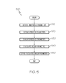
- Figure 5 illustrates a flow chart of a conceptual process used in some embodiments to configure various physical parameters of the porous blocker bar of Figure 2 ;
- Figure 6 illustrates a schematic diagram of a conceptual system used in some embodiments to implement the process of Figure 5 .
- embodiments of the present invention generally provide a way to reduce fatigue experienced by components of a heat exchanger and improve temperature gradients within the heat exchanger.
- the porous blocker bars of the present invention may be configured such that structural integrity of the heat exchanger may be improved and hot flow may be reduced and/or dampened. In this manner, the operating life and performance of the heat exchanger may be improved.
- Figure 1 illustrates a perspective view of a section of a plate-fin heat exchanger 100.
- this figure shows the various components of the heat exchanger 100, which may include a cold fluid pathway 110, a hot fluid pathway 120, cold bars 130, cold fins 140, hot bars 150, hot fins 160, side plate 170, and/or tube sheets 180.
- Figure 1 shows the hot-cold corner 190 and the hot-hot corner 195 of the heat exchanger 100.
- Such a heat exchanger may further include a second side plate (omitted for clarity) at the opposite side of the heat exchanger 100 from the first side plate 170.
- Figure 2 illustrates a perspective view of a section of a plate-fin heat exchanger 200 including porous blocker bars 210 according to an exemplary embodiment of the present invention.
- the blocker bars may be placed at each inlet and/or outlet to each flow passageway.
- Such porous blocker bars may provide improved structural integrity, reinforcing the tube sheets 180 and more evenly distributing loads across the passage width of the hot inlet face.
- the blocker bars may reduce global and local temperature gradients within the passages of the heat exchanger by increasing local capacitance, thus slowing down metal temperature reaction rates in critical areas.
- the temperature gradients may also be improved by restricting the amount of hot fluid flow that can enter the passages.
- each porous blocker bar 210 may include multiple "pores" 220 (i.e., enclosed passageways that may allow fluid to flow through the porous blocker bar).
- the pores 220 may be round through-holes oriented along one axis of the blocker bar 210.
- the heat exchanger 200 may be sealed and connected in such a way that the operating parameters of the hot fluid pathway 120 may be determined by the pores 220. In this manner, the pores may be used to control hot flow through the heat exchanger (e.g., by configuring the pores to have an appropriate size and/or spacing for the desired flow).
- the porous blocker bars 210 and/or the pores 220 may utilize application-specific configurations, as described in more detail below.
- the cold fluid pathway 110 may allow cold fluid to pass through the heat exchanger 200 in a first direction (indicated by arrow 110).
- the cold bars 130 may be arranged such that the bars seal the edges of the cold fluid pathway 110 along the direction of flow.
- the cold fins 140 may be arranged such that the fins allow fluid to flow along the cold fluid pathway 110.
- the hot fluid pathway 120 may allow hot fluid to pass through the heat exchanger in a second direction (indicated by arrow 120).
- the hot bars 150 may be arranged such that the bars seal the edges of the hot fluid pathway 120 along the direction of flow.
- the hot fins 160 may be arranged such that the fins allow fluid to flow along the hot fluid pathway 120.
- the side plate (or plates) 170 and tube sheets 180 may be arranged such that the pathways 110-120 each allow flow along a single axis.
- Each fluid pathway may include a number of flow passages (i.e., flow paths at each level of the pathway).
- pores 220 are represented as round through-holes in the example of Figure 2 , one of ordinary skill in the art will recognize that different embodiments may include different pores, as appropriate.
- some embodiments may include pores that have non-round shapes (e.g., square, triangular, octagonal, etc.) or are otherwise irregularly-shaped (e.g., ellipses, non-symmetrical polygons, etc.).
- some embodiments may include different pores (e.g., a single embodiment may include round and non-round pores).
- some embodiments may include non-uniformly sized pores (e.g., the pores may be sized to be smaller at the ends of the blocker bar and larger near the center of the blocker bar, or vice-versa).
- the various components of the heat exchanger 200 may be made from various appropriate materials (e.g., steel, aluminum, titanium, etc.) and/or combinations of materials.
- the heat exchanger may include different numbers of various components, as appropriate (e.g., based on the size of the heat exchanger, operating temperatures, flow requirements, etc.). Such components may be arranged in various appropriate ways. For example, different embodiments may include different numbers of flow passages. As another example, different embodiments may include different numbers of hot and/or cold bars (and interceding hot and/or cold fins) at each passage.
- Figure 3 illustrates a perspective view of the porous blocker bar 210.
- the blocker bar may have a generally rectangular shape, where the shape may be defined by a width 310, depth 320, and height 330.
- Different embodiments may utilize different blocker bars, as appropriate (e.g., bars of varying size, shape, etc.).
- the pores 220 may run from a front face 340 of the blocker bar to a rear face.
- the front face may be situated to face toward the direction of the hot fluid pathway 120 (i.e., the inlet end of the pathway) while the rear face may be situated to face toward the outlet end of the pathway.
- the pores are arranged at constant spacing along the middle of the front face 340, however, the pores may be arranged in various appropriate ways (e.g., a grid of offset pores, sets of pores at various locations along the face, etc.).
- Figure 4 illustrates a top view of a section of the porous blocker bar 210, specifically highlighting the size 410 and spacing 420 of pores 220 along the porous blocker bar.
- the pores run from the front face 340 to the rear face 430.
- the size 410 of the pores 220 is defined by a diameter of the through-hole, while the spacing 420 is defined by a distance along a second axis of the blocker bar.
- the pores 220 are shown in this example as having a constant diameter through the entire depth 320 of the blocker bar 210, different embodiments may have differently-shaped pores (e.g., the pores may taper from a larger diameter at the inlet side of the blocker bar to a smaller diameter at the outlet side of the blocker bar, or vice-versa).
- Figure 5 illustrates a flow chart of a conceptual process 500 used in some embodiments to configure various physical parameters of the porous blocker bar 210.
- Such application-specific configurations may allow the porous blocker bars to be optimized for use in a variety of heat exchangers that may correspond to a variety of applications.
- the process may be performed by a system such as the system 600 described below.
- Process 500 may begin when a user begins design of a porous blocker bar. As shown, the process may receive (at 510) dimensional parameters. Such dimensional parameters may include the size and/or shape of the blocker bar, desired pore size, etc. Next, the process may receive (at 520) various operating parameters for the blocker bar. Such operating parameters may include minimum and/or maximum flow rates, operating temperatures, etc. In addition, the operating parameters may include various user-desired performance of the heat exchanger (e.g., temperature gradients, heat exchange, operating life, etc.).
- dimensional parameters may include the size and/or shape of the blocker bar, desired pore size, etc.
- various operating parameters for the blocker bar Such operating parameters may include minimum and/or maximum flow rates, operating temperatures, etc.
- the operating parameters may include various user-desired performance of the heat exchanger (e.g., temperature gradients, heat exchange, operating life, etc.).
- the process may then evaluate (at 530) the parameters received at 510 and 520. Such evaluation may include comparing the received parameters to various thresholds or tolerances, any limitations of the manufacturing facility, etc.
- the process may then calculate (at 540) various design parameters. Such calculation may involve performing a set of mathematical operations, optimizing results for a particular manufacturing facility, etc.
- the design parameters may include the size, shape, and/or spacing of pores to be included in the blocker bar.
- the process may store (at 550) the calculated design parameters and then end. The stored design parameters may then be available for use in designing and manufacturing the blocker bars.
- process 500 has been described with reference to various details, one of ordinary skill in the art will recognize that the process may be performed in various appropriate ways without departing from the spirit of the invention. For instance, the operations of the process may be performed in various different orders. As another example, only a subset of operations may be performed in some embodiments, or the process may be performed as a set of sub-processes. As yet another example, the process may be performed as a sub-process of another process.
- Figure 6 illustrates a schematic diagram of a conceptual system 600 used in some embodiments to implement process 500.
- the system 600 may include a bus 610, one or more processors 620, one or more input/output devices 630, one or more storages 640, and/or one or more network interface(s).
- the system may be implemented using a variety of specific devices, either alone or in conjunction (e.g., a mobile device, a personal computer, a tablet device, a Smartphone, a server, etc.) and/or a variety of communication pathways, either alone or in conjunction (e.g., physical pathways such as wires and cables, wireless pathways, etc.).
- the bus 610 conceptually represents all communication pathways available to the system 600.
- the processor(s) 620 may include various computing devices (e.g., microprocessors, digital signal processors, application-specific integrated circuits, etc.).
- the input/output device(s) 630 may include input devices such as mice, keyboards, etc., and/or output devices such as monitors, printers, etc.
- the storage(s) 640 may include various transitory and/or non-transitory storage(s) (e.g., RAM storage, ROM storage, "cloud” storage, etc.).
- the network interface(s) 650 may include various circuitry and/or software that allow the system 600 to connect to one or more networks (e.g., a local-area network, a wide-area network, etc.) or one or more networks of networks (e.g., the Internet).
- networks e.g., a local-area network, a wide-area network, etc.
- networks of networks e.g., the Internet
- System 600 may be used to execute the operations of, for instance, process 500.
- process 500 may be implemented using sets of software instructions. Such sets of software instructions may be stored in storage 640 such that they may be retrieved and executed by processor 620.
- data such as dimensional parameters and/or operating parameters may be stored in storage 640.
- Processor 620 may retrieve and use the data when executing the software instructions to evaluate the received parameters and calculate the design parameters.
- the processor 620 may send the calculated design parameters to the storage 640. In this manner, the calculated design parameters may be made available to various appropriate manufacturing entities (e.g., the design parameters may be used to generate technical drawings that are supplied to a machine shop that will fabricate the porous blocker bars).
Landscapes
- Engineering & Computer Science (AREA)
- Physics & Mathematics (AREA)
- Thermal Sciences (AREA)
- Mechanical Engineering (AREA)
- General Engineering & Computer Science (AREA)
- Chemical & Material Sciences (AREA)
- Dispersion Chemistry (AREA)
- Heat-Exchange Devices With Radiators And Conduit Assemblies (AREA)
- Separation By Low-Temperature Treatments (AREA)
Applications Claiming Priority (1)
| Application Number | Priority Date | Filing Date | Title |
|---|---|---|---|
| US13/356,525 US9279626B2 (en) | 2012-01-23 | 2012-01-23 | Plate-fin heat exchanger with a porous blocker bar |
Publications (2)
| Publication Number | Publication Date |
|---|---|
| EP2618094A2 true EP2618094A2 (fr) | 2013-07-24 |
| EP2618094A3 EP2618094A3 (fr) | 2016-08-24 |
Family
ID=47598679
Family Applications (1)
| Application Number | Title | Priority Date | Filing Date |
|---|---|---|---|
| EP13150885.5A Withdrawn EP2618094A3 (fr) | 2012-01-23 | 2013-01-10 | Barre de blocage poreuse pour échangeur de chaleur à ailettes |
Country Status (2)
| Country | Link |
|---|---|
| US (1) | US9279626B2 (fr) |
| EP (1) | EP2618094A3 (fr) |
Cited By (1)
| Publication number | Priority date | Publication date | Assignee | Title |
|---|---|---|---|---|
| EP3462119B1 (fr) | 2013-04-30 | 2021-03-31 | Hamilton Sundstrand Corporation | Distributeur d'échangeur de chaleur intégré |
Families Citing this family (10)
| Publication number | Priority date | Publication date | Assignee | Title |
|---|---|---|---|---|
| DE102012016442A1 (de) * | 2012-08-18 | 2014-02-20 | Audi Ag | Wärmetauscher |
| US20160377350A1 (en) * | 2015-06-29 | 2016-12-29 | Honeywell International Inc. | Optimized plate fin heat exchanger for improved compliance to improve thermal life |
| CN105790027B (zh) * | 2016-03-08 | 2019-02-12 | 京东方科技集团股份有限公司 | 一种外引线压接装置 |
| EP3473961B1 (fr) | 2017-10-20 | 2020-12-02 | Api Heat Transfer, Inc. | Échangeur de chaleur |
| US10544997B2 (en) | 2018-03-16 | 2020-01-28 | Hamilton Sundstrand Corporation | Angled fluid redistribution slot in heat exchanger fin layer |
| US12510308B2 (en) * | 2018-04-05 | 2025-12-30 | Rtx Corporation | Heat augmentation features in a cast heat exchanger |
| US11076510B2 (en) * | 2018-08-13 | 2021-07-27 | Facebook Technologies, Llc | Heat management device and method of manufacture |
| US11221186B2 (en) * | 2019-07-18 | 2022-01-11 | Hamilton Sundstrand Corporation | Heat exchanger closure bar with shield |
| US11828501B2 (en) * | 2019-07-30 | 2023-11-28 | Ut-Battelle, Llc | Metal foam heat exchangers for air and gas cooling and heating applications |
| FR3130359B1 (fr) | 2021-12-13 | 2024-04-26 | Liebherr Aerospace Toulouse Sas | Dispositif d’échange thermique comprenant au moins un dispositif limiteur de débit, système de conditionnement d’air et véhicule |
Citations (1)
| Publication number | Priority date | Publication date | Assignee | Title |
|---|---|---|---|---|
| DE202008013351U1 (de) * | 2008-10-08 | 2010-03-25 | Autokühler GmbH & Co. KG | Wärmeaustauschernetz und damit ausgerüsteter Wärmeaustauscher |
Family Cites Families (134)
| Publication number | Priority date | Publication date | Assignee | Title |
|---|---|---|---|---|
| US2401797A (en) * | 1943-12-27 | 1946-06-11 | Gen Motors Corp | Heat exchanger |
| US3587730A (en) * | 1956-08-30 | 1971-06-28 | Union Carbide Corp | Heat exchange system with porous boiling layer |
| US3262190A (en) * | 1961-07-10 | 1966-07-26 | Iit Res Inst | Method for the production of metallic heat transfer bodies |
| US3272260A (en) * | 1961-08-11 | 1966-09-13 | Union Carbide Corp | Corrosion resistant heat exchanger |
| US3306353A (en) * | 1964-12-23 | 1967-02-28 | Olin Mathieson | Heat exchanger with sintered metal matrix around tubes |
| US3302704A (en) * | 1965-05-14 | 1967-02-07 | Olin Mathieson | Compound metal structure |
| US3502141A (en) * | 1965-12-23 | 1970-03-24 | Nasa | Method of improving heat transfer characteristics in a nucleate boiling process |
| US3490718A (en) * | 1967-02-01 | 1970-01-20 | Nasa | Capillary radiator |
| US3607369A (en) * | 1968-09-11 | 1971-09-21 | Union Carbide Corp | Method for forming porous aluminum layer |
| US3613778A (en) * | 1969-03-03 | 1971-10-19 | Northrop Corp | Flat plate heat pipe with structural wicks |
| US4051898A (en) * | 1969-03-20 | 1977-10-04 | Mitsubishi Denki Kabushiki Kaisha | Static heat-and-moisture exchanger |
| US3559722A (en) * | 1969-09-16 | 1971-02-02 | Trane Co | Method and apparatus for two-phase heat exchange fluid distribution in plate-type heat exchangers |
| US3590914A (en) * | 1969-10-01 | 1971-07-06 | Trane Co | Countercurrent flow plate-type heat exchanger with leak detector |
| US3595310A (en) * | 1969-11-12 | 1971-07-27 | Olin Corp | Modular units and use thereof in heat exchangers |
| US3732919A (en) * | 1970-07-01 | 1973-05-15 | J Wilson | Heat exchanger |
| US3598180A (en) * | 1970-07-06 | 1971-08-10 | Robert David Moore Jr | Heat transfer surface structure |
| US3776303A (en) * | 1971-04-27 | 1973-12-04 | Olin Corp | Heat exchanger |
| JPS548202B2 (fr) * | 1972-12-07 | 1979-04-13 | ||
| DE2315268C3 (de) * | 1973-03-27 | 1978-08-17 | Hermann J. Prof. 8000 Muenchen Schladitz | Elektrische Heizvorrichtung |
| US3905203A (en) * | 1973-06-15 | 1975-09-16 | Carlyle W Jacob | Refrigeration and water condensate removal apparatus |
| JPS5325379B2 (fr) * | 1974-10-21 | 1978-07-26 | ||
| US3983191A (en) * | 1975-11-10 | 1976-09-28 | The Trane Company | Brazed plate-type heat exchanger for nonadiabatic rectification |
| US4222434A (en) * | 1978-04-27 | 1980-09-16 | Clyde Robert A | Ceramic sponge heat-exchanger member |
| JPS555152A (en) * | 1978-06-28 | 1980-01-16 | Hitachi Ltd | Production of heat exchanger |
| US4274479A (en) * | 1978-09-21 | 1981-06-23 | Thermacore, Inc. | Sintered grooved wicks |
| JPS5579996A (en) * | 1978-12-14 | 1980-06-16 | Teijin Ltd | Wet heat exchanger |
| JPS5924357B2 (ja) * | 1980-06-23 | 1984-06-08 | 株式会社神戸製鋼所 | 水素収蔵体を利用した熱交換装置 |
| DE3107010C2 (de) * | 1981-02-25 | 1985-02-28 | Dieter Christian Steinegg-Appenzell Steeb | Metallkühler zum Kühlen eines unter hohem Druck durchströmenden Fluids durch Luft |
| US4460388A (en) * | 1981-07-17 | 1984-07-17 | Nippon Soken, Inc. | Total heat exchanger |
| JPS60238688A (ja) * | 1984-05-11 | 1985-11-27 | Mitsubishi Electric Corp | 熱交換器 |
| DE3521914A1 (de) * | 1984-06-20 | 1986-01-02 | Showa Aluminum Corp., Sakai, Osaka | Waermetauscher in fluegelplattenbauweise |
| US4694378A (en) * | 1984-12-21 | 1987-09-15 | Hitachi, Ltd. | Apparatus for cooling integrated circuit chips |
| EP0223995B1 (fr) * | 1985-10-25 | 1990-01-17 | Elpag Ag Chur | Echangeur de chaleur |
| JP2569003B2 (ja) * | 1986-03-20 | 1997-01-08 | 株式会社日立製作所 | 熱伝導装置 |
| US4699209A (en) * | 1986-03-27 | 1987-10-13 | Air Products And Chemicals, Inc. | Heat exchanger design for cryogenic reboiler or condenser service |
| US4715431A (en) * | 1986-06-09 | 1987-12-29 | Air Products And Chemicals, Inc. | Reboiler-condenser with boiling and condensing surfaces enhanced by extrusion |
| US4715433A (en) * | 1986-06-09 | 1987-12-29 | Air Products And Chemicals, Inc. | Reboiler-condenser with doubly-enhanced plates |
| US4871623A (en) * | 1988-02-19 | 1989-10-03 | Minnesota Mining And Manufacturing Company | Sheet-member containing a plurality of elongated enclosed electrodeposited channels and method |
| US4898234A (en) * | 1988-08-19 | 1990-02-06 | Mcdonnell Douglas Corporation | Air heat exchanger |
| US5441716A (en) * | 1989-03-08 | 1995-08-15 | Rocky Research | Method and apparatus for achieving high reaction rates |
| DE3937809A1 (de) * | 1989-11-14 | 1991-05-16 | Schwaebische Huettenwerke Gmbh | Filter zum abscheiden von verunreinigungen |
| US5205353A (en) * | 1989-11-30 | 1993-04-27 | Akzo N.V. | Heat exchanging member |
| US5123982A (en) * | 1990-06-29 | 1992-06-23 | The United States Of American As Represented By The United States Department Of Energy | Process of making cryogenically cooled high thermal performance crystal optics |
| JP3122173B2 (ja) * | 1990-11-09 | 2001-01-09 | 株式会社東芝 | 放熱器、放熱装置および放熱器の製造方法 |
| DE4110285A1 (de) * | 1991-03-28 | 1992-10-01 | Schwaebische Huettenwerke Gmbh | Filter- oder katalysatorkoerper |
| US5125451A (en) * | 1991-04-02 | 1992-06-30 | Microunity Systems Engineering, Inc. | Heat exchanger for solid-state electronic devices |
| JPH0566073A (ja) * | 1991-09-05 | 1993-03-19 | Sanden Corp | 積層型熱交換器 |
| US6983788B2 (en) * | 1998-11-09 | 2006-01-10 | Building Performance Equipment, Inc. | Ventilating system, heat exchanger and methods |
| IL108860A (en) * | 1994-03-04 | 1998-10-30 | Elisra Gan Ltd | Heat radiating element |
| US5437328A (en) * | 1994-04-21 | 1995-08-01 | International Business Machines Corporation | Multi-stage heat sink |
| US5564496A (en) * | 1994-11-01 | 1996-10-15 | United Technologies Corporation | Composite parting sheet |
| CZ286800B6 (cs) * | 1994-12-20 | 2000-07-12 | Mircea Dinulescu | Tepelný výměník |
| US5960861A (en) * | 1995-04-05 | 1999-10-05 | Raytheon Company | Cold plate design for thermal management of phase array-radar systems |
| US5957194A (en) * | 1996-06-27 | 1999-09-28 | Advanced Thermal Solutions, Inc. | Plate fin heat exchanger having fluid control means |
| US6054229A (en) * | 1996-07-19 | 2000-04-25 | Ztek Corporation | System for electric generation, heating, cooling, and ventilation |
| JPH1054691A (ja) * | 1996-08-08 | 1998-02-24 | Mitsubishi Electric Corp | 熱交換器の間隔板及び熱交換器用部材及び熱交換器並びにその製造方法 |
| US20020092643A1 (en) * | 1996-11-26 | 2002-07-18 | Fawcett Sherwood Luther | Confined bed metal particulate heat exchanger |
| US5847927A (en) * | 1997-01-27 | 1998-12-08 | Raytheon Company | Electronic assembly with porous heat exchanger and orifice plate |
| US6032726A (en) * | 1997-06-30 | 2000-03-07 | Solid State Cooling Systems | Low-cost liquid heat transfer plate and method of manufacturing therefor |
| US6037032A (en) * | 1997-09-02 | 2000-03-14 | Lockheed Martin Energy Research Corp. | Pitch-based carbon foam heat sink with phase change material |
| US5823249A (en) * | 1997-09-03 | 1998-10-20 | Batchelder; John Samual | Manifold for controlling interdigitated counterstreaming fluid flows |
| US5884691A (en) * | 1997-09-03 | 1999-03-23 | Batchelder; John Samual | Fluid transmissive moderated flow resistance heat transfer unit |
| JPH11204709A (ja) | 1998-01-19 | 1999-07-30 | Denso Corp | 沸騰冷却装置 |
| KR19990085965A (ko) * | 1998-05-23 | 1999-12-15 | 박호군 | 다공핀 평판관형 열교환기 |
| US6576199B1 (en) * | 1998-09-18 | 2003-06-10 | Alliedsignal Inc. | Environmental control system including ozone-destroying catalytic converter having anodized and washcoat layers |
| US6378605B1 (en) * | 1999-12-02 | 2002-04-30 | Midwest Research Institute | Heat exchanger with transpired, highly porous fins |
| KR20010076991A (ko) * | 2000-01-29 | 2001-08-17 | 박호군 | 발포금속 방열기 |
| US6424529B2 (en) * | 2000-03-14 | 2002-07-23 | Delphi Technologies, Inc. | High performance heat exchange assembly |
| US6840307B2 (en) * | 2000-03-14 | 2005-01-11 | Delphi Technologies, Inc. | High performance heat exchange assembly |
| US6761211B2 (en) * | 2000-03-14 | 2004-07-13 | Delphi Technologies, Inc. | High-performance heat sink for electronics cooling |
| US20020153129A1 (en) * | 2000-04-25 | 2002-10-24 | White Stephen L. | Integral fin passage heat exchanger |
| JP2002154801A (ja) * | 2000-11-15 | 2002-05-28 | Japan Steel Works Ltd:The | 水素貯蔵容器用通気材 |
| US20020108743A1 (en) * | 2000-12-11 | 2002-08-15 | Wirtz Richard A. | Porous media heat sink apparatus |
| US6424531B1 (en) * | 2001-03-13 | 2002-07-23 | Delphi Technologies, Inc. | High performance heat sink for electronics cooling |
| NL1018672C2 (nl) * | 2001-07-31 | 2003-02-06 | Stichting Energie | Stelsel voor het strippen en rectificeren van een fluïdummengsel. |
| US7124812B1 (en) * | 2001-09-28 | 2006-10-24 | Honeywell International, Inc. | Heat exchanger |
| JP3652635B2 (ja) * | 2001-10-15 | 2005-05-25 | 核燃料サイクル開発機構 | 中間熱媒体を有する熱交換器 |
| DK2244327T3 (da) * | 2002-02-05 | 2012-05-07 | Tokyo Gas Co Ltd | Fastoxidbrændselscellesystem |
| US6591897B1 (en) * | 2002-02-20 | 2003-07-15 | Delphi Technologies, Inc. | High performance pin fin heat sink for electronics cooling |
| US7014835B2 (en) * | 2002-08-15 | 2006-03-21 | Velocys, Inc. | Multi-stream microchannel device |
| US6834515B2 (en) * | 2002-09-13 | 2004-12-28 | Air Products And Chemicals, Inc. | Plate-fin exchangers with textured surfaces |
| TWI300466B (en) * | 2002-11-01 | 2008-09-01 | Cooligy Inc | Channeled flat plate fin heat exchange system, device and method |
| WO2004042306A2 (fr) * | 2002-11-01 | 2004-05-21 | Cooligy, Inc. | Procede et appareil d'obtention de l'uniformite thermique et de refroidissement de point chaud dans un dispositif de production de chaleur |
| US20050211418A1 (en) * | 2002-11-01 | 2005-09-29 | Cooligy, Inc. | Method and apparatus for efficient vertical fluid delivery for cooling a heat producing device |
| US6986382B2 (en) * | 2002-11-01 | 2006-01-17 | Cooligy Inc. | Interwoven manifolds for pressure drop reduction in microchannel heat exchangers |
| US8464781B2 (en) * | 2002-11-01 | 2013-06-18 | Cooligy Inc. | Cooling systems incorporating heat exchangers and thermoelectric layers |
| US20050211427A1 (en) * | 2002-11-01 | 2005-09-29 | Cooligy, Inc. | Method and apparatus for flexible fluid delivery for cooling desired hot spots in a heat producing device |
| US20050211417A1 (en) * | 2002-11-01 | 2005-09-29 | Cooligy,Inc. | Interwoven manifolds for pressure drop reduction in microchannel heat exchangers |
| US7836597B2 (en) * | 2002-11-01 | 2010-11-23 | Cooligy Inc. | Method of fabricating high surface to volume ratio structures and their integration in microheat exchangers for liquid cooling system |
| WO2004070284A1 (fr) * | 2003-02-03 | 2004-08-19 | Lg Electronics Inc. | Echangeur thermique de systeme de ventilation |
| JP3961443B2 (ja) * | 2003-04-08 | 2007-08-22 | 本田技研工業株式会社 | 蒸発器 |
| GB0324348D0 (en) * | 2003-10-17 | 2003-11-19 | Oxycom Bv | Heat exchange laminate |
| US7013956B2 (en) * | 2003-09-02 | 2006-03-21 | Thermal Corp. | Heat pipe evaporator with porous valve |
| US7044199B2 (en) * | 2003-10-20 | 2006-05-16 | Thermal Corp. | Porous media cold plate |
| US7017655B2 (en) * | 2003-12-18 | 2006-03-28 | Modine Manufacturing Co. | Forced fluid heat sink |
| US20070053168A1 (en) * | 2004-01-21 | 2007-03-08 | General Electric Company | Advanced heat sinks and thermal spreaders |
| US7549460B2 (en) * | 2004-04-02 | 2009-06-23 | Adaptivenergy, Llc | Thermal transfer devices with fluid-porous thermally conductive core |
| JP4120611B2 (ja) | 2004-04-08 | 2008-07-16 | 株式会社デンソー | 冷媒蒸発器 |
| EP1751479B1 (fr) * | 2004-04-09 | 2014-05-14 | Ail Research Inc. | Echangeur de chaleur et de masse |
| JP2005326136A (ja) * | 2004-04-16 | 2005-11-24 | Daikin Ind Ltd | 空気熱交換器用伝熱フィン |
| JP3767611B2 (ja) * | 2004-04-28 | 2006-04-19 | ダイキン工業株式会社 | 吸着熱交換器 |
| JP2006125767A (ja) * | 2004-10-29 | 2006-05-18 | Tokyo Institute Of Technology | 熱交換器 |
| RU2382310C2 (ru) * | 2004-11-03 | 2010-02-20 | Велосис, Инк. | Способ парциального кипячения в мини- и микроканалах |
| JP4975970B2 (ja) * | 2005-01-21 | 2012-07-11 | 日本エクスラン工業株式会社 | 収着式熱交換モジュールおよびその製法 |
| US7467467B2 (en) * | 2005-09-30 | 2008-12-23 | Pratt & Whitney Canada Corp. | Method for manufacturing a foam core heat exchanger |
| US7353864B2 (en) | 2005-12-23 | 2008-04-08 | Hamilton Sundstrand Corporation | Apparatus for reducing thermal fatigue in heat exchanger cores |
| US20070235174A1 (en) * | 2005-12-23 | 2007-10-11 | Dakhoul Youssef M | Heat exchanger |
| US7331381B2 (en) * | 2006-02-16 | 2008-02-19 | Allcomp, Inc. | Hybrid heat exchangers |
| US20070228113A1 (en) * | 2006-03-28 | 2007-10-04 | Dupree Ronald L | Method of manufacturing metallic foam based heat exchanger |
| JP2007285598A (ja) * | 2006-04-17 | 2007-11-01 | Matsushita Electric Ind Co Ltd | 熱交換器 |
| US8505616B2 (en) * | 2006-04-20 | 2013-08-13 | The Boeing Company | Hybrid ceramic core cold plate |
| US8162035B2 (en) * | 2006-04-20 | 2012-04-24 | The Boeing Company | High conductivity ceramic foam cold plate |
| US7905275B2 (en) * | 2006-04-20 | 2011-03-15 | The Boeing Company | Ceramic foam cold plate |
| US20090101321A1 (en) * | 2006-05-03 | 2009-04-23 | Tat Technologies Ltd. | Heat Exchanger |
| WO2007149535A1 (fr) * | 2006-06-21 | 2007-12-27 | Ben Strauss | Nid d'abeille doté d'une fraction de parois cellulaires sensiblement poreuses |
| JP4725560B2 (ja) * | 2006-09-29 | 2011-07-13 | 株式会社デンソー | 吸着モジュールおよび吸着モジュールの製造方法 |
| US8191616B2 (en) * | 2006-11-02 | 2012-06-05 | The Boeing Company | Combined thermal protection and surface temperature control system |
| US7604782B1 (en) * | 2007-01-22 | 2009-10-20 | The United States Of America As Represented By The National Aeronautics And Space Administration | Heat rejection sublimator |
| US8162042B2 (en) * | 2007-01-22 | 2012-04-24 | Building Performance Equipment, Inc. | Energy recovery ventilator with condensate feedback |
| JP4231081B2 (ja) * | 2007-01-31 | 2009-02-25 | 株式会社東芝 | 冷却装置 |
| US8371365B2 (en) * | 2007-05-03 | 2013-02-12 | Brayton Energy, Llc | Heat exchange device and method for manufacture |
| CN101340796B (zh) * | 2007-07-04 | 2010-09-29 | 富准精密工业(深圳)有限公司 | 散热装置 |
| US8069912B2 (en) * | 2007-09-28 | 2011-12-06 | Caterpillar Inc. | Heat exchanger with conduit surrounded by metal foam |
| US20090145581A1 (en) * | 2007-12-11 | 2009-06-11 | Paul Hoffman | Non-linear fin heat sink |
| US20090308571A1 (en) * | 2008-05-09 | 2009-12-17 | Thermal Centric Corporation | Heat transfer assembly and methods therefor |
| US8129036B2 (en) * | 2008-05-13 | 2012-03-06 | Hamilton Sundstrand Space Systems International, Inc. | High strength and high thermal conductivity heat transfer apparatus |
| US8347503B2 (en) * | 2008-06-30 | 2013-01-08 | Uop Llc | Methods of manufacturing brazed aluminum heat exchangers |
| US8322406B2 (en) * | 2008-07-14 | 2012-12-04 | University Of Central Florida Research Foundation, Inc. | Thermally conductive porous element-based recuperators |
| JP5128544B2 (ja) * | 2009-04-20 | 2013-01-23 | 株式会社神戸製鋼所 | プレートフィン熱交換器 |
| TW201111734A (en) * | 2009-09-16 | 2011-04-01 | Chenming Mold Ind Corp | Heat dissipation module and manufacturing method thereof |
| KR101183292B1 (ko) * | 2010-01-14 | 2012-09-14 | 웅진코웨이주식회사 | 열교환기, 상기 열교환기를 포함하는 음식물 처리기 및 상기 열교환기의 제조 방법 |
| US8881797B2 (en) * | 2010-05-05 | 2014-11-11 | Ametek, Inc. | Compact plate-fin heat exchanger utilizing an integral heat transfer layer |
| US8953314B1 (en) * | 2010-08-09 | 2015-02-10 | Georgia Tech Research Corporation | Passive heat sink for dynamic thermal management of hot spots |
| US20120193083A1 (en) * | 2011-02-02 | 2012-08-02 | Hamilton Sundstrand Space Systems International, Inc. | Heat exchanger assembly with fin locating structure |
-
2012
- 2012-01-23 US US13/356,525 patent/US9279626B2/en active Active
-
2013
- 2013-01-10 EP EP13150885.5A patent/EP2618094A3/fr not_active Withdrawn
Patent Citations (1)
| Publication number | Priority date | Publication date | Assignee | Title |
|---|---|---|---|---|
| DE202008013351U1 (de) * | 2008-10-08 | 2010-03-25 | Autokühler GmbH & Co. KG | Wärmeaustauschernetz und damit ausgerüsteter Wärmeaustauscher |
Cited By (1)
| Publication number | Priority date | Publication date | Assignee | Title |
|---|---|---|---|---|
| EP3462119B1 (fr) | 2013-04-30 | 2021-03-31 | Hamilton Sundstrand Corporation | Distributeur d'échangeur de chaleur intégré |
Also Published As
| Publication number | Publication date |
|---|---|
| US20130191079A1 (en) | 2013-07-25 |
| EP2618094A3 (fr) | 2016-08-24 |
| US9279626B2 (en) | 2016-03-08 |
Similar Documents
| Publication | Publication Date | Title |
|---|---|---|
| US9279626B2 (en) | Plate-fin heat exchanger with a porous blocker bar | |
| Jarrett et al. | Design optimization of electric vehicle battery cooling plates for thermal performance | |
| Arsenyeva et al. | The influence of plate corrugations geometry on plate heat exchanger performance in specified process conditions | |
| Ravishankar et al. | Numerical studies on thermal performance of novel cooling plate designs in polymer electrolyte membrane fuel cell stacks | |
| Huang et al. | The study on the improvement of system uniformity flow rate for U-type compact heat exchangers | |
| Yuan et al. | Two energy conservation principles in convective heat transfer optimization | |
| Junqi et al. | Experimental study of wavy fin aluminum plate fin heat exchanger | |
| Tian et al. | Numerical simulation of finned tube bank across a staggered circular-pin-finned tube bundle | |
| CN103150439B (zh) | 面向板翅式换热器设计的翅片流动与换热性能预测方法 | |
| Zhang et al. | Fluid flow distribution and heat transfer in plate-fin heat exchangers | |
| CN103899404B (zh) | 发动机冷却系统评估方法、评估装置及挖掘机 | |
| Saito et al. | Experimental and numerical performance evaluation of double-lift absorption heat transformer | |
| CN118536429A (zh) | 一种多相流数值分析方法及系统 | |
| Gaur et al. | Performance optimization of triple tube heat exchanger using aluminum metal foam: A comprehensive numerical investigation | |
| Saeedan et al. | Metal foam as a turbulent flow distributor in the cooling channels of a PEM fuel cell—a numerical study | |
| CN203980996U (zh) | 混沌流道及对应的隔板、翅片结构 | |
| Ismael et al. | Radiator heat dissipation performance | |
| Krishnan et al. | Numerical investigation of fluid flow and heat transfer in periodic porous lattice-flame materials | |
| Huang et al. | Airflow distribution and design optimization of variable geometry microchannel heat exchangers | |
| Huang et al. | Design and numerical parametric study of a compact air-cooled heat exchanger | |
| Zhou et al. | Thermal performance of a novel honeycomb cooling system for cylindrical lithium-ion batteries | |
| Zhang et al. | Fluid flow and heat transfer in plate-fin and tube heat exchangers in a transitional flow regime | |
| Kulacki et al. | On the effectiveness of baffles in indirect solar storage systems | |
| Ejaz et al. | Comparative analysis of airside thermal–hydraulic behavior of plain, wavy, and louver fins under humid conditions | |
| Lai et al. | A large eddy simulation of plate-fin and tube heat exchangers with small diameter tubes |
Legal Events
| Date | Code | Title | Description |
|---|---|---|---|
| PUAI | Public reference made under article 153(3) epc to a published international application that has entered the european phase |
Free format text: ORIGINAL CODE: 0009012 |
|
| 17P | Request for examination filed |
Effective date: 20130110 |
|
| AK | Designated contracting states |
Kind code of ref document: A2 Designated state(s): AL AT BE BG CH CY CZ DE DK EE ES FI FR GB GR HR HU IE IS IT LI LT LU LV MC MK MT NL NO PL PT RO RS SE SI SK SM TR |
|
| AX | Request for extension of the european patent |
Extension state: BA ME |
|
| RAP1 | Party data changed (applicant data changed or rights of an application transferred) |
Owner name: HONEYWELL INTERNATIONAL INC. |
|
| PUAL | Search report despatched |
Free format text: ORIGINAL CODE: 0009013 |
|
| AK | Designated contracting states |
Kind code of ref document: A3 Designated state(s): AL AT BE BG CH CY CZ DE DK EE ES FI FR GB GR HR HU IE IS IT LI LT LU LV MC MK MT NL NO PL PT RO RS SE SI SK SM TR |
|
| AX | Request for extension of the european patent |
Extension state: BA ME |
|
| RIC1 | Information provided on ipc code assigned before grant |
Ipc: F28F 13/00 20060101ALI20160718BHEP Ipc: F28F 9/02 20060101AFI20160718BHEP Ipc: F28D 9/00 20060101ALI20160718BHEP |
|
| 17Q | First examination report despatched |
Effective date: 20170719 |
|
| STAA | Information on the status of an ep patent application or granted ep patent |
Free format text: STATUS: THE APPLICATION IS DEEMED TO BE WITHDRAWN |
|
| 18D | Application deemed to be withdrawn |
Effective date: 20181121 |