EP2619782B1 - Schutzschalter für eine hochspannungsstromleitung mit einer in einem verbindungskanal angeordneten insertionsvorrichtung - Google Patents
Schutzschalter für eine hochspannungsstromleitung mit einer in einem verbindungskanal angeordneten insertionsvorrichtung Download PDFInfo
- Publication number
- EP2619782B1 EP2619782B1 EP11757656.1A EP11757656A EP2619782B1 EP 2619782 B1 EP2619782 B1 EP 2619782B1 EP 11757656 A EP11757656 A EP 11757656A EP 2619782 B1 EP2619782 B1 EP 2619782B1
- Authority
- EP
- European Patent Office
- Prior art keywords
- contact
- tank
- circuit breaker
- terminal
- resistor
- Prior art date
- Legal status (The legal status is an assumption and is not a legal conclusion. Google has not performed a legal analysis and makes no representation as to the accuracy of the status listed.)
- Not-in-force
Links
Images

Classifications
-
- H—ELECTRICITY
- H01—ELECTRIC ELEMENTS
- H01H—ELECTRIC SWITCHES; RELAYS; SELECTORS; EMERGENCY PROTECTIVE DEVICES
- H01H33/00—High-tension or heavy-current switches with arc-extinguishing or arc-preventing means
- H01H33/02—Details
- H01H33/04—Means for extinguishing or preventing arc between current-carrying parts
- H01H33/16—Impedances connected with contacts
-
- H—ELECTRICITY
- H01—ELECTRIC ELEMENTS
- H01H—ELECTRIC SWITCHES; RELAYS; SELECTORS; EMERGENCY PROTECTIVE DEVICES
- H01H33/00—High-tension or heavy-current switches with arc-extinguishing or arc-preventing means
- H01H33/02—Details
- H01H2033/028—Details the cooperating contacts being both actuated simultaneously in opposite directions
-
- H—ELECTRICITY
- H01—ELECTRIC ELEMENTS
- H01H—ELECTRIC SWITCHES; RELAYS; SELECTORS; EMERGENCY PROTECTIVE DEVICES
- H01H33/00—High-tension or heavy-current switches with arc-extinguishing or arc-preventing means
- H01H33/02—Details
- H01H33/04—Means for extinguishing or preventing arc between current-carrying parts
- H01H33/16—Impedances connected with contacts
- H01H33/166—Impedances connected with contacts the impedance being inserted only while closing the switch
Definitions
- the invention relates to a device for breaking, or circuit breaker, of a medium, high or very high voltage electricity transmission line comprising a double-contact interrupting chamber and a resistance insertion device in the line. .
- the invention relates more particularly to a circuit breaker comprising two parallel tanks each receiving a breaking chamber and a resistance, and the two tanks are interconnected by at least one connecting conduit.
- the two tanks communicate with each other at their ends by transverse conduits, and a device for inserting the resistor is arranged in one end of the tank receiving the resistor, to connect or not the resistance to the breaking chamber.
- the insertion device is arranged in the tank receiving the resistance, and a drive mechanism of the insertion device is mounted at the end of the tank, at the level of the device. 'insertion.
- the drive of the insertion device is then performed independently to drive the interrupting chamber.
- the document US 2009067108 proposes to drive the insertion device by the driving means of the interrupting chamber by means of a return mechanism.
- the drive mechanism of the insertion device has been replaced by the return mechanism, which means that the component number of the circuit breaker has been reduced only to a limited extent.
- the object of the invention is to propose a circuit breaker for which the number of components associated with the insertion device is even smaller.
- a reduced number of components is arranged in the vessel receiving the resistance, which limits the general volume of this vessel.
- the circuit breaker comprises a drive member of the interrupting chamber which is located at the first terminal of the interrupting chamber, and in that the drive means of the movable contact are connected directly to said actuator member. training.
- the circuit breaker comprises a drive member of the interrupting chamber which is located at the second terminal of the interrupting chamber, and in that the drive means of the movable contact are connected directly to said actuator member. training.
- At least one contact of the insertion device extends at least partly through the transverse duct.
- the second contact is fixed and is arranged in the transverse duct.
- the second contact is fixed and is arranged in the second tank.
- the first contact is movable between a position of contact with the second contact and a position remote from the second contact in which the whole of the movable contact is located in the first tank.
- the first contact is movable between a position of contact with the second contact and a position remote from the second contact in which at least a portion of the movable contact is located in the transverse duct.
- figure 1 a circuit breaker 10 for a medium, high or very high voltage line.
- the circuit breaker 10 comprises a breaking chamber 12 which is arranged inside a first tank 14 made of electrically conductive material, for example aluminum alloy, or stainless steel.
- the breaking chamber 12 extends along a longitudinal principal axis A, and the first tank 14 is substantially coaxial with the breaking chamber 12.
- the interrupting chamber 12 is here of the double-contact type of contact, that is to say that it comprises a fixed contact and a movable contact (not shown) which are both axially movable in the interrupting chamber 12 so as to move toward or away from each other, to open or close the streamline.
- the circuit breaker 10 is of the in-line motion input type, that is to say it comprises an actuator 16 located at an axial end of the interrupting chamber 12, here at the left end in FIG. referring to the figures.
- the actuator 16 comprises in particular an axial rod 18 which is slidably mounted axially in the interrupting chamber 12, which drives the contacts of the interrupting chamber, for the opening or closing of the breaking chamber 12.
- Each end 12a, 12b of the interrupting chamber 12 is connected to a conductor (not shown) of the stream line, and the tank 16 comprises two conduits 20, each of which is associated with a conductor, which open into the interior volume of the tank, at the associated end 12a, 12b of the interrupting chamber 12, to allow the connection of the conductor of the current line to the associated end 12a, 12b of the breaking chamber 12.
- the circuit breaker 10 also comprises a resistor 22 which is intended to be connected in parallel with the breaking chamber 12 by an insertion device 24 of the resistor, in parallel with the interrupting chamber.
- the insertion of the resistor 22 makes it possible to limit the overvoltage effects present on the power transmission line during the closing of the breaking chamber 12.
- resistor 22 also makes it possible to limit the call currents when energizing transformers or reactors.
- the resistor 22 is of longitudinal main orientation and is offset transversely with respect to the breaking chamber 12.
- the resistor 22 is arranged inside a second tank 26 of main orientation longitudinally substantially coaxial with the resistor 22.
- the second tank 26 comprises support means 44 of the resistor 22 which are made of electrically insulating material.
- the two tanks 14, 26 are parallel and offset transversely relative to one another, and they are connected to each other at the longitudinal ends of the tanks 14, 26 via two transverse ducts. 28.
- Each of the two transverse ducts 28 is made from two tubular portions 40, 42 formed in the first tank 14 and in the second tank 26, respectively, and each of which extends transversely to the other tank 26, 14 and whose free transverse end 40a 42a forms a flange which is connected.
- the free transverse end 40a, 42a of each tubular portion 40, 42 is connected to the free transverse end 42a, 40a vis-à-vis the other tubular portion 40, 42 by welding or any other known method of attachment.
- transverse ducts 28 connect the two interior volumes of the tanks 14, 26 to form a single volume.
- an insulating support is arranged between the free ends 40a, 42a of the tubular portions 40, 42.
- This insulating support is gas-tight and thus isolates the interior volumes tanks 14, 26, thus forming two separate gas volumes, commonly called “partitions”.
- the insulating support comprises a gas-tight insulating membrane, a metal central insert allowing the electrical connection through the conduit 28 and a peripheral flange which is also metallic for the electrical connection of the tanks 14, 26 to each other.
- transverse ducts 28 are traversed by means for connecting the resistor 22 to the interrupting chamber 12.
- the transverse duct 28 located on the right at the figure 1 is crossed by a conductor 30 which electrically connects the right end terminal 12b of the breaking chamber 12 to the right end terminal 22b of the resistor 22.
- the conductor 30 also forms, in this embodiment, a support of the resistor 22 in the second tank 26, at the right end 22b of the resistor 22.
- the tank 26 comprises a second support 44 made of insulating material, which connects the left end 22a of the resistor 22 to the left end of the second tank 26.
- the resistor 22 is carried by two insulating supports 44, each of which is arranged at one end 22a, 22b of the resistor 22.
- the transverse duct 28 located on the left at the figure 1 is traversed by a portion of the insertion device 24, so that the end terminal of left 22a of the resistor 22 is connectable selectively to the left end terminal 12a of the breaking chamber 12 by the insertion device 24.
- the insertion device 24 generally consists of a switch arranged between the terminals or left ends 12a, 22a of the breaking chamber 12 and the resistor 22.
- the insertion device 24 comprises a fixed contact 32, which is here permanently connected with the left terminal 22a of the resistor, a movable contact 34 which is permanently connected with the left terminal 12a of the interrupting chamber 12, and means 36 for driving the movable contact 34 to a position of contact with the fixed contact 32, or to a position remote from the fixed contact 32.
- the movable contact comprises a transverse rod 38, which is slidably mounted and which is guided in translation by a guide element of the drive means 36.
- the free transverse end 38a of the rod 38, which is closest to the fixed contact 32 is formed to come into electrical contact with the fixed contact 32.
- At least one contact 32, 34 of the insertion device 24 extends at least partially in the duct 28 on the left which passes through the insertion device 24, when the movable contact 34 is in the remote position or when the movable contact 34 is in the position of contact with the fixed contact 32.
- the drive means 36 of the movable contact 34 are arranged in the first tank 14, close to the left terminal 12a of the interrupting chamber 12, which is located near the actuator 16 for driving the chamber. cutoff 12.
- the drive means 36 of the movable contact are connected directly to the longitudinal rod 18 so as to be driven by the actuator 16 without the intermediary of a return device.
- the fixed contact 32 is arranged inside the second tank 26, at the left terminal 22a of the resistor 22.
- the fixed contact 34 is movable in the left duct 28 between the remote position shown in FIG. figure 1 in which the fixed contact 34 extends through the left duct 28 and a contact position in which at least the free end 38a of the movable contact 34 is in contact with the fixed contact 32 and is located in the end left of the second tank 26.
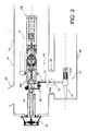
- FIG. 2 an alternative embodiment of the circuit breaker 10 in which the fixed contact 32 is located inside the left duct 28, and the movable contact 34 is movable transversely between the contact position in which the free transverse end 38a of the rod 38 is located in the left duct 28 and a remote position in which all of the movable contact 34 is located in the first tank 16, at a distance from the fixed contact 32.
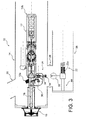
- FIG. 3 still another alternative embodiment of the circuit breaker wherein the fixed contact is arranged inside the second tank 26, at the left terminal 22a of the resistor 22, and wherein the movable contact 34 is located at the inside the first tank 14 when it is in the remote position.
- circuit breaker 10 has been described in association with a resistance insertion device in parallel with the breaking chamber 12. It will be understood that the invention also relates to a resistance insertion device in series with the breaking chamber. 12.
- the insertion device 24 which has been described comprises a single moving contact 34, it will also be understood that the invention relates to a double-contact type insertion device, for which the two contacts 32, 34 are movable in the circuit breaker and relative to each other.
- the actuator 16 and the axial rod 18 for actuating the breaking chamber 12 are arranged at the second end 12b of the breaking chamber 12, and the drive means 36 of the mobile contact 34 are connected directly to the axial rod 18.
- the central insert of the insulator forms part of the fixed contact 32 of the device. insertion 24.
- the fixed contact 32 extends in part inside the conduit 28 and the movable contact 26 extends inside the conduit when it is in the connected position with the fixed contact.
Landscapes
- Circuit Breakers (AREA)
- Arc-Extinguishing Devices That Are Switches (AREA)
Claims (8)
- Schalter (10) für eine Stromleitung mit mittlerer, hoher oder sehr hoher Spannung, umfassend- wenigstens eine Unterbrecherkammer (12) mit longitudinaler Hauptachse A, die in einem im Wesentlichen longitudinalen ersten Behälter (14) angeordnet ist;- wenigstens einen Widerstand (22) mit longitudinaler Hauptachse B, der in einem im Wesentlichen longitudinalen zweiten Behälter (26) angeordnet ist, wobei der zweite Behälter (26) transversal bezüglich des ersten Behälters (14) versetzt ist,- eine Transversalleitung (28) zur Verbindung des ersten Behälters (14) mit dem zweiten Behälter (26), die longitudinal im Bereich eines ersten Anschlusses (12a) der Unterbrecherkammer (12) angeordnet ist,- eine Einfügevorrichtung (24) für den Widerstand (22), die dazu ausgelegt ist, einen ersten Anschluss (22a) des Widerstands (22) elektrisch mit dem ersten Anschluss (12a) der Unterbrecherkammer (12) zu verbinden, die einen ersten mobilen Kontakt (34) umfasst, der mit dem ersten Anschluss (12a) der Unterbrecherkammer (12) oder mit dem ersten Anschluss (22a) des Widerstands (22) verbunden und dazu ausgelegt ist, in elektrischen Kontakt mit einem zweiten Kontakt (32) der Einfügevorrichtung (24) zu gelangen, der mit dem ersten Anschluss (22a) des Widerstands (22) beziehungsweise mit dem ersten Anschluss (12a) der Unterbrecherkammer (12) verbunden ist,
wobei die Einfügevorrichtung (24) Mittel (36) zum Antrieb des mobilen Kontakts (34) umfasst, die in dem ersten Behälter (14) im Bereich des ersten Anschlusses (12a) der Unterbrecherkammer (12) angeordnet sind,
dadurch gekennzeichnet, dass der mobile Kontakt (34) teilweise in der transversalen Verbindungsleitung (28) verlagerbar ist. - Schalter (10) nach Anspruch 1, dadurch gekennzeichnet, dass er ein Organ (18) zum Antrieb der Unterbrecherkammer (12) umfasst, das im Bereich des ersten Anschlusses (12a) der Unterbrecherkammer (12) angeordnet ist, und dass die Antriebsmittel (36) des mobilen Kontakts (34) direkt mit dem Antriebsorgan (18) verbunden sind.
- Schalter (10) nach Anspruch 1, dadurch gekennzeichnet, dass er ein Organ (18) zum Antrieb der Unterbrecherkammer (12) umfasst, das im Bereich des zweiten Anschlusses (12b) der Unterbrecherkammer (12) angeordnet ist, und dass die Antriebsmittel (36) des mobilen Kontakts (34) direkt mit dem Antriebsorgan (18) verbunden sind.
- Schalter (10) nach einem der vorhergehenden Ansprüche, dadurch gekennzeichnet, dass wenigstens ein Kontakt (32, 34) der Einfügevorrichtung (24) sich wenigstens teilweise durch die Transversalleitung (28) hindurch erstreckt.
- Schalter (10) nach Anspruch 4, dadurch gekennzeichnet, dass der zweite Kontakt (32) fest und in der Transversalleitung (28) angeordnet ist.
- Schalter (10) nach Anspruch 4, dadurch gekennzeichnet, dass der zweite Kontakt (32) fest und in dem zweiten Behälter (26) angeordnet ist.
- Schalter (10) nach Anspruch 5 oder 6, dadurch gekennzeichnet, dass der erste Kontakt (34) mobil ist zwischen einer Kontaktposition mit dem zweiten Kontakt (32) und einer vom zweiten Kontakt (32) entfernten Position, in der der gesamte mobile Kontakt (34) in dem ersten Behälter (14) befindlich ist.
- Schalter (10) nach Anspruch 5 oder 6, dadurch gekennzeichnet, dass der erste Kontakt (34) mobil ist zwischen einer Kontaktposition mit dem zweiten Kontakt (32) und einer vom zweiten Kontakt (32) entfernten Position, in der wenigstens ein Teil des mobilen Kontakts (34) in der Transversalleitung (28) befindlich ist.
Applications Claiming Priority (2)
| Application Number | Priority Date | Filing Date | Title |
|---|---|---|---|
| FR1057546A FR2965098B1 (fr) | 2010-09-21 | 2010-09-21 | Disjoncteur de ligne a haute tension comportant un dispositif d'insertion agence dans un conduit de liaison |
| PCT/EP2011/066286 WO2012038405A1 (fr) | 2010-09-21 | 2011-09-20 | Disjoncteur de ligne a haute tension comportant un dispositif d'insertion agence dans un conduit de liaison. |
Publications (2)
| Publication Number | Publication Date |
|---|---|
| EP2619782A1 EP2619782A1 (de) | 2013-07-31 |
| EP2619782B1 true EP2619782B1 (de) | 2014-06-18 |
Family
ID=43896899
Family Applications (1)
| Application Number | Title | Priority Date | Filing Date |
|---|---|---|---|
| EP11757656.1A Not-in-force EP2619782B1 (de) | 2010-09-21 | 2011-09-20 | Schutzschalter für eine hochspannungsstromleitung mit einer in einem verbindungskanal angeordneten insertionsvorrichtung |
Country Status (3)
| Country | Link |
|---|---|
| EP (1) | EP2619782B1 (de) |
| FR (1) | FR2965098B1 (de) |
| WO (1) | WO2012038405A1 (de) |
Families Citing this family (3)
| Publication number | Priority date | Publication date | Assignee | Title |
|---|---|---|---|---|
| US9064647B2 (en) * | 2012-09-06 | 2015-06-23 | Abb Technology Ag | Contact alignment structure for high-voltage dead tank circuit breakers |
| US9105427B2 (en) * | 2012-09-14 | 2015-08-11 | Abb Technology Ag | Telescoping current path structure for dual tank dead tank circuit breaker with parallel resistor assembly |
| CN104143469A (zh) * | 2013-11-15 | 2014-11-12 | 国家电网公司 | 断路器合闸电阻脱扣机构及使用该机构的断路器 |
Family Cites Families (3)
| Publication number | Priority date | Publication date | Assignee | Title |
|---|---|---|---|---|
| JPS5576526A (en) * | 1978-12-01 | 1980-06-09 | Hitachi Ltd | Gas breaker |
| DE502007004867D1 (de) * | 2007-09-10 | 2010-10-07 | Abb Technology Ag | Einschaltwiderstand für Hochspannungsleistungsschalter |
| CN101855694B (zh) * | 2007-09-10 | 2014-04-23 | Abb技术有限公司 | 具有用于接入合闸电阻的开关的高压功率开关 |
-
2010
- 2010-09-21 FR FR1057546A patent/FR2965098B1/fr not_active Expired - Fee Related
-
2011
- 2011-09-20 WO PCT/EP2011/066286 patent/WO2012038405A1/fr not_active Ceased
- 2011-09-20 EP EP11757656.1A patent/EP2619782B1/de not_active Not-in-force
Also Published As
| Publication number | Publication date |
|---|---|
| FR2965098A1 (fr) | 2012-03-23 |
| EP2619782A1 (de) | 2013-07-31 |
| FR2965098B1 (fr) | 2015-03-06 |
| WO2012038405A1 (fr) | 2012-03-29 |
Similar Documents
| Publication | Publication Date | Title |
|---|---|---|
| EP0433184A1 (de) | Hybrid-Mittelspannungsschalter | |
| EP2619782B1 (de) | Schutzschalter für eine hochspannungsstromleitung mit einer in einem verbindungskanal angeordneten insertionsvorrichtung | |
| EP3493235A1 (de) | Vakuumlampe für elektrisches stromunterbrechungsgerät | |
| EP0913845A1 (de) | Generatorlastschalter mit einer einzelnen mechanischen Betätigung | |
| EP0240397B1 (de) | Selbstbeblasender elektrischer Lastschalter mit rotierendem Lichtbogen | |
| EP1897107B1 (de) | Unterdruck-birne für eine elektrische schutzvorrichtung wie etwa einen schalter oder einen unterbrecherschalter | |
| CA2079555C (fr) | Disjoncteur ultra haute tension | |
| EP4343808B1 (de) | Nichtelektrische vorrichtung zum ersetzen eines stromsensors in einer schaltkammer eines lasttrennschalters sowie lasttrennschalter mit einer solchen nicht-elektrischen vorrichtung | |
| EP3968350B1 (de) | Vakuumlampe für stromunterbrechungsgerät | |
| FR2483121A1 (fr) | Sectionneur de poste blinde a haute tension | |
| EP3182431B1 (de) | Elektrisches schaltgerät | |
| EP3227897B1 (de) | Elektrische tripout-vorrichtung mit einem schutzschalter und isolator | |
| FR2811137A1 (fr) | Bielle de manoeuvre pour disjoncteur haute tension | |
| EP1512160B1 (de) | Metallgekapselte hochspannungsachaltanlage mit einem leistungsschalter und mit einer stromschiene montierten einschaltwiderstand | |
| EP2144263B1 (de) | Elektrogeräte unter einer Metallhülle mit reduziertem Spannungsgradienten | |
| EP2735012B1 (de) | Trennschalter für eine gasisolierte anlage mit einer vakuumröhre | |
| EP2682970B1 (de) | Schaltgerät mit Mitteln zum geschlossenhalten elektrischer Kontakte | |
| CN111095464B (zh) | 用于在高、中和/或低压技术中切换大电流的装置和方法 | |
| EP2959494B1 (de) | Schaltvorrichtung mit einer bewegbaren elektrode | |
| EP4639597A1 (de) | Hochspannungsschaltkammer | |
| FR3012690A1 (fr) | Module pour psem | |
| EP2248141B1 (de) | Zweikontakt-kontaktor und bogenausblaskamin | |
| FR2773909A1 (fr) | Disjoncteur a double mouvement avec un dispositif d'insertion d'une resistance de fermeture | |
| FR2989822A1 (fr) | Appareil electrique d'interruption de circuit protege contre des surtensions | |
| EP3142134A1 (de) | Assistenzsystem zur detektion einer störung eines trennschalters, das an mittel- und hochspannungen angepasst ist |
Legal Events
| Date | Code | Title | Description |
|---|---|---|---|
| PUAI | Public reference made under article 153(3) epc to a published international application that has entered the european phase |
Free format text: ORIGINAL CODE: 0009012 |
|
| 17P | Request for examination filed |
Effective date: 20130321 |
|
| AK | Designated contracting states |
Kind code of ref document: A1 Designated state(s): AL AT BE BG CH CY CZ DE DK EE ES FI FR GB GR HR HU IE IS IT LI LT LU LV MC MK MT NL NO PL PT RO RS SE SI SK SM TR |
|
| DAX | Request for extension of the european patent (deleted) | ||
| GRAP | Despatch of communication of intention to grant a patent |
Free format text: ORIGINAL CODE: EPIDOSNIGR1 |
|
| INTG | Intention to grant announced |
Effective date: 20140114 |
|
| GRAS | Grant fee paid |
Free format text: ORIGINAL CODE: EPIDOSNIGR3 |
|
| GRAA | (expected) grant |
Free format text: ORIGINAL CODE: 0009210 |
|
| AK | Designated contracting states |
Kind code of ref document: B1 Designated state(s): AL AT BE BG CH CY CZ DE DK EE ES FI FR GB GR HR HU IE IS IT LI LT LU LV MC MK MT NL NO PL PT RO RS SE SI SK SM TR |
|
| REG | Reference to a national code |
Ref country code: GB Ref legal event code: FG4D Free format text: NOT ENGLISH |
|
| REG | Reference to a national code |
Ref country code: CH Ref legal event code: EP |
|
| REG | Reference to a national code |
Ref country code: AT Ref legal event code: REF Ref document number: 673772 Country of ref document: AT Kind code of ref document: T Effective date: 20140715 |
|
| REG | Reference to a national code |
Ref country code: IE Ref legal event code: FG4D Free format text: LANGUAGE OF EP DOCUMENT: FRENCH |
|
| REG | Reference to a national code |
Ref country code: CH Ref legal event code: NV Representative=s name: BOVARD AG, CH Ref country code: DE Ref legal event code: R096 Ref document number: 602011007827 Country of ref document: DE Effective date: 20140731 |
|
| REG | Reference to a national code |
Ref country code: SE Ref legal event code: TRGR |
|
| PG25 | Lapsed in a contracting state [announced via postgrant information from national office to epo] |
Ref country code: LT Free format text: LAPSE BECAUSE OF FAILURE TO SUBMIT A TRANSLATION OF THE DESCRIPTION OR TO PAY THE FEE WITHIN THE PRESCRIBED TIME-LIMIT Effective date: 20140618 Ref country code: FI Free format text: LAPSE BECAUSE OF FAILURE TO SUBMIT A TRANSLATION OF THE DESCRIPTION OR TO PAY THE FEE WITHIN THE PRESCRIBED TIME-LIMIT Effective date: 20140618 Ref country code: GR Free format text: LAPSE BECAUSE OF FAILURE TO SUBMIT A TRANSLATION OF THE DESCRIPTION OR TO PAY THE FEE WITHIN THE PRESCRIBED TIME-LIMIT Effective date: 20140919 Ref country code: CY Free format text: LAPSE BECAUSE OF FAILURE TO SUBMIT A TRANSLATION OF THE DESCRIPTION OR TO PAY THE FEE WITHIN THE PRESCRIBED TIME-LIMIT Effective date: 20140618 Ref country code: NO Free format text: LAPSE BECAUSE OF FAILURE TO SUBMIT A TRANSLATION OF THE DESCRIPTION OR TO PAY THE FEE WITHIN THE PRESCRIBED TIME-LIMIT Effective date: 20140918 |
|
| REG | Reference to a national code |
Ref country code: NL Ref legal event code: VDEP Effective date: 20140618 |
|
| REG | Reference to a national code |
Ref country code: AT Ref legal event code: MK05 Ref document number: 673772 Country of ref document: AT Kind code of ref document: T Effective date: 20140618 |
|
| REG | Reference to a national code |
Ref country code: LT Ref legal event code: MG4D |
|
| PG25 | Lapsed in a contracting state [announced via postgrant information from national office to epo] |
Ref country code: HR Free format text: LAPSE BECAUSE OF FAILURE TO SUBMIT A TRANSLATION OF THE DESCRIPTION OR TO PAY THE FEE WITHIN THE PRESCRIBED TIME-LIMIT Effective date: 20140618 Ref country code: RS Free format text: LAPSE BECAUSE OF FAILURE TO SUBMIT A TRANSLATION OF THE DESCRIPTION OR TO PAY THE FEE WITHIN THE PRESCRIBED TIME-LIMIT Effective date: 20140618 Ref country code: LV Free format text: LAPSE BECAUSE OF FAILURE TO SUBMIT A TRANSLATION OF THE DESCRIPTION OR TO PAY THE FEE WITHIN THE PRESCRIBED TIME-LIMIT Effective date: 20140618 |
|
| PG25 | Lapsed in a contracting state [announced via postgrant information from national office to epo] |
Ref country code: RO Free format text: LAPSE BECAUSE OF FAILURE TO SUBMIT A TRANSLATION OF THE DESCRIPTION OR TO PAY THE FEE WITHIN THE PRESCRIBED TIME-LIMIT Effective date: 20140618 Ref country code: EE Free format text: LAPSE BECAUSE OF FAILURE TO SUBMIT A TRANSLATION OF THE DESCRIPTION OR TO PAY THE FEE WITHIN THE PRESCRIBED TIME-LIMIT Effective date: 20140618 Ref country code: ES Free format text: LAPSE BECAUSE OF FAILURE TO SUBMIT A TRANSLATION OF THE DESCRIPTION OR TO PAY THE FEE WITHIN THE PRESCRIBED TIME-LIMIT Effective date: 20140618 Ref country code: CZ Free format text: LAPSE BECAUSE OF FAILURE TO SUBMIT A TRANSLATION OF THE DESCRIPTION OR TO PAY THE FEE WITHIN THE PRESCRIBED TIME-LIMIT Effective date: 20140618 Ref country code: PT Free format text: LAPSE BECAUSE OF FAILURE TO SUBMIT A TRANSLATION OF THE DESCRIPTION OR TO PAY THE FEE WITHIN THE PRESCRIBED TIME-LIMIT Effective date: 20141020 Ref country code: SK Free format text: LAPSE BECAUSE OF FAILURE TO SUBMIT A TRANSLATION OF THE DESCRIPTION OR TO PAY THE FEE WITHIN THE PRESCRIBED TIME-LIMIT Effective date: 20140618 |
|
| PG25 | Lapsed in a contracting state [announced via postgrant information from national office to epo] |
Ref country code: AT Free format text: LAPSE BECAUSE OF FAILURE TO SUBMIT A TRANSLATION OF THE DESCRIPTION OR TO PAY THE FEE WITHIN THE PRESCRIBED TIME-LIMIT Effective date: 20140618 Ref country code: IS Free format text: LAPSE BECAUSE OF FAILURE TO SUBMIT A TRANSLATION OF THE DESCRIPTION OR TO PAY THE FEE WITHIN THE PRESCRIBED TIME-LIMIT Effective date: 20141018 Ref country code: NL Free format text: LAPSE BECAUSE OF FAILURE TO SUBMIT A TRANSLATION OF THE DESCRIPTION OR TO PAY THE FEE WITHIN THE PRESCRIBED TIME-LIMIT Effective date: 20140618 Ref country code: PL Free format text: LAPSE BECAUSE OF FAILURE TO SUBMIT A TRANSLATION OF THE DESCRIPTION OR TO PAY THE FEE WITHIN THE PRESCRIBED TIME-LIMIT Effective date: 20140618 |
|
| REG | Reference to a national code |
Ref country code: DE Ref legal event code: R097 Ref document number: 602011007827 Country of ref document: DE |
|
| PLBE | No opposition filed within time limit |
Free format text: ORIGINAL CODE: 0009261 |
|
| STAA | Information on the status of an ep patent application or granted ep patent |
Free format text: STATUS: NO OPPOSITION FILED WITHIN TIME LIMIT |
|
| PG25 | Lapsed in a contracting state [announced via postgrant information from national office to epo] |
Ref country code: MC Free format text: LAPSE BECAUSE OF FAILURE TO SUBMIT A TRANSLATION OF THE DESCRIPTION OR TO PAY THE FEE WITHIN THE PRESCRIBED TIME-LIMIT Effective date: 20140618 Ref country code: DK Free format text: LAPSE BECAUSE OF FAILURE TO SUBMIT A TRANSLATION OF THE DESCRIPTION OR TO PAY THE FEE WITHIN THE PRESCRIBED TIME-LIMIT Effective date: 20140618 Ref country code: IT Free format text: LAPSE BECAUSE OF FAILURE TO SUBMIT A TRANSLATION OF THE DESCRIPTION OR TO PAY THE FEE WITHIN THE PRESCRIBED TIME-LIMIT Effective date: 20140618 Ref country code: LU Free format text: LAPSE BECAUSE OF FAILURE TO SUBMIT A TRANSLATION OF THE DESCRIPTION OR TO PAY THE FEE WITHIN THE PRESCRIBED TIME-LIMIT Effective date: 20140920 |
|
| 26N | No opposition filed |
Effective date: 20150319 |
|
| REG | Reference to a national code |
Ref country code: IE Ref legal event code: MM4A |
|
| PG25 | Lapsed in a contracting state [announced via postgrant information from national office to epo] |
Ref country code: BE Free format text: LAPSE BECAUSE OF NON-PAYMENT OF DUE FEES Effective date: 20140930 |
|
| PG25 | Lapsed in a contracting state [announced via postgrant information from national office to epo] |
Ref country code: SI Free format text: LAPSE BECAUSE OF FAILURE TO SUBMIT A TRANSLATION OF THE DESCRIPTION OR TO PAY THE FEE WITHIN THE PRESCRIBED TIME-LIMIT Effective date: 20140618 |
|
| PG25 | Lapsed in a contracting state [announced via postgrant information from national office to epo] |
Ref country code: IE Free format text: LAPSE BECAUSE OF NON-PAYMENT OF DUE FEES Effective date: 20140920 |
|
| REG | Reference to a national code |
Ref country code: FR Ref legal event code: PLFP Year of fee payment: 5 |
|
| PGFP | Annual fee paid to national office [announced via postgrant information from national office to epo] |
Ref country code: CH Payment date: 20150904 Year of fee payment: 5 Ref country code: DE Payment date: 20150914 Year of fee payment: 5 |
|
| PGFP | Annual fee paid to national office [announced via postgrant information from national office to epo] |
Ref country code: SE Payment date: 20150916 Year of fee payment: 5 |
|
| PGFP | Annual fee paid to national office [announced via postgrant information from national office to epo] |
Ref country code: FR Payment date: 20150930 Year of fee payment: 5 |
|
| PG25 | Lapsed in a contracting state [announced via postgrant information from national office to epo] |
Ref country code: SM Free format text: LAPSE BECAUSE OF FAILURE TO SUBMIT A TRANSLATION OF THE DESCRIPTION OR TO PAY THE FEE WITHIN THE PRESCRIBED TIME-LIMIT Effective date: 20140618 |
|
| GBPC | Gb: european patent ceased through non-payment of renewal fee |
Effective date: 20150920 |
|
| PG25 | Lapsed in a contracting state [announced via postgrant information from national office to epo] |
Ref country code: MT Free format text: LAPSE BECAUSE OF FAILURE TO SUBMIT A TRANSLATION OF THE DESCRIPTION OR TO PAY THE FEE WITHIN THE PRESCRIBED TIME-LIMIT Effective date: 20140618 Ref country code: BG Free format text: LAPSE BECAUSE OF FAILURE TO SUBMIT A TRANSLATION OF THE DESCRIPTION OR TO PAY THE FEE WITHIN THE PRESCRIBED TIME-LIMIT Effective date: 20140618 |
|
| PG25 | Lapsed in a contracting state [announced via postgrant information from national office to epo] |
Ref country code: GB Free format text: LAPSE BECAUSE OF NON-PAYMENT OF DUE FEES Effective date: 20150920 Ref country code: HU Free format text: LAPSE BECAUSE OF FAILURE TO SUBMIT A TRANSLATION OF THE DESCRIPTION OR TO PAY THE FEE WITHIN THE PRESCRIBED TIME-LIMIT; INVALID AB INITIO Effective date: 20110920 |
|
| REG | Reference to a national code |
Ref country code: DE Ref legal event code: R119 Ref document number: 602011007827 Country of ref document: DE |
|
| PG25 | Lapsed in a contracting state [announced via postgrant information from national office to epo] |
Ref country code: SE Free format text: LAPSE BECAUSE OF NON-PAYMENT OF DUE FEES Effective date: 20160921 |
|
| REG | Reference to a national code |
Ref country code: CH Ref legal event code: PL |
|
| REG | Reference to a national code |
Ref country code: SE Ref legal event code: EUG |
|
| REG | Reference to a national code |
Ref country code: FR Ref legal event code: ST Effective date: 20170531 |
|
| PG25 | Lapsed in a contracting state [announced via postgrant information from national office to epo] |
Ref country code: DE Free format text: LAPSE BECAUSE OF NON-PAYMENT OF DUE FEES Effective date: 20170401 Ref country code: FR Free format text: LAPSE BECAUSE OF NON-PAYMENT OF DUE FEES Effective date: 20160930 Ref country code: CH Free format text: LAPSE BECAUSE OF NON-PAYMENT OF DUE FEES Effective date: 20160930 Ref country code: LI Free format text: LAPSE BECAUSE OF NON-PAYMENT OF DUE FEES Effective date: 20160930 |
|
| PG25 | Lapsed in a contracting state [announced via postgrant information from national office to epo] |
Ref country code: TR Free format text: LAPSE BECAUSE OF FAILURE TO SUBMIT A TRANSLATION OF THE DESCRIPTION OR TO PAY THE FEE WITHIN THE PRESCRIBED TIME-LIMIT Effective date: 20140618 |
|
| PG25 | Lapsed in a contracting state [announced via postgrant information from national office to epo] |
Ref country code: MK Free format text: LAPSE BECAUSE OF FAILURE TO SUBMIT A TRANSLATION OF THE DESCRIPTION OR TO PAY THE FEE WITHIN THE PRESCRIBED TIME-LIMIT Effective date: 20140618 |
|
| PG25 | Lapsed in a contracting state [announced via postgrant information from national office to epo] |
Ref country code: AL Free format text: LAPSE BECAUSE OF FAILURE TO SUBMIT A TRANSLATION OF THE DESCRIPTION OR TO PAY THE FEE WITHIN THE PRESCRIBED TIME-LIMIT Effective date: 20140618 |