EP2620559B1 - Strahlregler mit lagegesicherter Dichtung - Google Patents
Strahlregler mit lagegesicherter Dichtung Download PDFInfo
- Publication number
- EP2620559B1 EP2620559B1 EP12008092.4A EP12008092A EP2620559B1 EP 2620559 B1 EP2620559 B1 EP 2620559B1 EP 12008092 A EP12008092 A EP 12008092A EP 2620559 B1 EP2620559 B1 EP 2620559B1
- Authority
- EP
- European Patent Office
- Prior art keywords
- sealing ring
- insert
- shell
- insert component
- securing
- Prior art date
- Legal status (The legal status is an assumption and is not a legal conclusion. Google has not performed a legal analysis and makes no representation as to the accuracy of the status listed.)
- Active
Links
Images

Classifications
-
- F—MECHANICAL ENGINEERING; LIGHTING; HEATING; WEAPONS; BLASTING
- F16—ENGINEERING ELEMENTS AND UNITS; GENERAL MEASURES FOR PRODUCING AND MAINTAINING EFFECTIVE FUNCTIONING OF MACHINES OR INSTALLATIONS; THERMAL INSULATION IN GENERAL
- F16J—PISTONS; CYLINDERS; SEALINGS
- F16J15/00—Sealings
- F16J15/02—Sealings between relatively-stationary surfaces
- F16J15/06—Sealings between relatively-stationary surfaces with solid packing compressed between sealing surfaces
- F16J15/061—Sealings between relatively-stationary surfaces with solid packing compressed between sealing surfaces with positioning means
-
- E—FIXED CONSTRUCTIONS
- E03—WATER SUPPLY; SEWERAGE
- E03C—DOMESTIC PLUMBING INSTALLATIONS FOR FRESH WATER OR WASTE WATER; SINKS
- E03C1/00—Domestic plumbing installations for fresh water or waste water; Sinks
- E03C1/02—Plumbing installations for fresh water
- E03C1/08—Jet regulators or jet guides, e.g. anti-splash devices
Definitions
- the invention relates to a sanitary insert with an insert housing, the housing peripheral wall has a sleeve-shaped inflow side housing edge region, and with a disc-shaped sealing ring which at least partially abuts with its outer circumference of the circumference of the sleeve peripheral housing edge region, wherein between the outer circumference of the disc sealing ring and the WandungsinnenANC the housing edge region a sealing ring Provision is made, which has at least one securing projection which is provided on the inner wall circumference of the housing edge region or on the outer circumference of the sealing ring and which protrudes into an associated therewith securing groove or the like Sich ceremoniessseinformung on each other component.
- sanitary inserts that can be used in an outlet nozzle, which can be attached to the water outlet of a sanitary outlet fitting.
- a sealing ring is provided, which is clamped in the interior of the outlet nozzle between the usually designed as a jet regulator insert and the downstream end edge of the water outlet and axially seals.
- the unit consisting of the outlet mouthpiece, insert part and sealing ring is secured by the sealing ring, which can be clamped inside the outlet mouthpiece and hold the insert part in the outlet mouthpiece.
- a sanitary insert of the type mentioned previously known which is designed as a jet regulator and serving as an insert outlet spout can be used.
- the peripheral wall of the outlet mouthpiece has an inflow-side housing edge region, on the Wandungsinnenjuri an internal thread is arranged, with which the outlet nozzle can be mounted on a, provided at the water outlet of a sanitary outlet fitting external thread.
- the outlet nozzle is located on a disc-shaped sealing ring with its outer circumference.
- a sealing ring safety device is provided between the outer disk circumference of the sealing ring and the inner wall circumference of the housing edge region of the outlet nozzle serving as an insert housing.
- the sealing ring has at its outer periphery of the disk a plurality of securing projections which are spaced apart from one another in the circumferential direction and which engage in the threads of the internal thread provided on the inner circumference of the wall of the outlet nozzle.
- the sealing ring Since the internal threading of the outlet mouthpiece which serves as a securing indentation of the sealing ring securing device increases continuously in the circumferential direction, the sealing ring must be inserted deeply into the inflow-side housing edge area of the outlet mouthpiece, such that the sealing ring Outside circumferential side protruding securing projections can engage in these threads.
- the outlet mouthpiece can affect the aesthetic impression of a sanitary outlet fitting, and since the outlet mouthpiece and the outlet fitting can be produced only with great effort with the same surface appearance, it has already created sanitary inserts, which have an external thread on the outer circumference of their housing housing with which the inserts can be screwed into an internal thread on the inner circumference of the water outlet of a sanitary outlet fitting such that the downstream housing side of the insertion only slightly protrudes beyond the water outlet or preferably terminates practically with it.
- Such an insert is for example in the DE 20 2010 014 392 U1 described in more detail. Even with these known inserts the parting plane between the insert and the water outlet is sealed.
- a sealing ring is provided, which can be inserted on the inflow side into the insertion housing, that the sealing ring only slightly immersed in the inlet side sleeve-shaped protruding housing front edge, whereby only very little radial bias can be applied to the sealing ring, thus jumping out of the sealing ring is avoided.
- the sealing ring inserted into the insert housing is sufficiently retained in the insert housing to be conveniently mounted in the water outlet together with the insert housing.
- the sealing ring with an inflow-side ring portion on the inflow-side end edge of the housing edge region over, so that the sealing ring can seal the dividing plane between an annular shoulder in the water outlet of the sanitary outlet fitting and the inflow side of the sanitary insert axially well.
- the insert according to the invention has a sealing ring-fuse, which is provided between the outer circumference of the disc sealing ring and the WandungsinnenANC the housing edge portion a sealing ring fuse which has at least one securing projection provided on the inner wall circumference of the housing edge region is and projects into a fuse associated with him or the like Sich ceremoniessseinformung on the sealing ring.
- the insert according to the invention has a sealing ring-securing, which is provided between the outer circumference of the disc sealing ring and the Wandungsinnenjuri the housing edge portion and holds the sealing ring securely in the insertion, for example, even in case of excessive vibration.
- This sealing ring fuse has a securing projection, which is provided on the inner wall circumference of the housing edge region and which projects into a securing groove or the like associated therewith securing recess on the sealing ring.
- a preferred embodiment according to the invention provides that the inflow-side end edge of the housing edge region adjoins the securing projection provided on the inner wall circumference and preferably merges into it.
- the securing projection can engage virtually centrally on the outer circumference of the sealing ring.
- the securing indentation In order to achieve a particularly good hold between the securing projection and the securing indentation of the sealing ring fuse, it is expedient for the securing indentation to have a clear cross section which conforms to the partial area of the securing projection which projects into the securing indentation.
- the housing edge region projects beyond an inner peripheral side adjacent recessed region of the inflow-side housing end face.
- the housing edge region may also be expedient for the housing edge region to protrude beyond a recessed area, which is adjacent to the inner circumference, of a functional element inserted into the insertion housing on the inflow side.
- the axial sealing effected with the sealing ring is favored when the sealing ring acts on at least one annular zone of the recessed region. If this annular zone is formed by an inner peripheral side adjacent recessed region of the inflow-side housing end face on the one hand and by a partial region of the inflow-side end face of a functional element inserted into the insertion housing, the sealing ring acting on this annular zone can also seal the annular gap formed between the two components.
- the securing projection or securing recess is preferably arranged approximately centrally in a median plane of the sealing ring. In this embodiment, it does not matter if the sealing ring is inserted with the one or the other disc end face in the insertion.
- the sealing ring has a chamfer or rounded at least on one of its outer corner regions. Even with such an embodiment, the automated assembly is much easier when the Sealing ring has at its two outer corner areas a chamfer or rounded.
- a preferred field of application of the present invention provides that the insert part is designed as a jet regulator.
- a development according to the invention provides that the insert carries on the housing outer circumference of its insert housing for screwing into an internal thread at the water outlet of a sanitary outlet fitting specific external thread.
- the insert can be dispensed with an outlet nozzle, wherein the limited to the insertion part and the sealing ring unit is held captive to each other here.
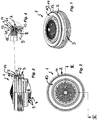
- FIGS. 1 to 4 is a sanitary insert 1 shown, which is designed here as a jet regulator.
- the insert part 1 has an insertion housing 2, which is mountable on the water outlet of a sanitary outlet fitting not shown here.
- On the outer circumference of the insert housing 2 to an external thread 3 is provided, with which the insert part 1 can be screwed into an internal thread in the water outlet until only at most an outflow-side portion of the insert housing 2 protrudes slightly above the water outlet or the insert housing 2 practically flush with the Water outlet closes.
- a flow rectifier 4 is provided which has a honeycomb cell-like structure with flow openings 5 has an approximately centrally located indentation 6, which is designed here as a coin slot. If necessary, a coin can also be used as a turning tool in this coin slot.
- the housing peripheral wall of the insert housing 2 has a sleeve-shaped inflow-side housing edge region 7 which projects beyond an inner peripheral side recessed region 8 of the inflow-side housing end face and over the inflow-side end face of a functional element 9 inserted into the insertion housing 2.
- the insert part 1 has a disc-shaped sealing ring 10 produced separately, which abuts at least partially with its outer circumference on the inner wall circumference of the sleeve-shaped housing edge region 7.
- the insert part 1 has a sealing ring-fuse, which is provided between the outer circumference of the disc sealing ring 10 and the Wandungsinnenin the housing edge portion 7 and holds the sealing ring 10 securely in the insertion housing 2, for example, even with excessive shock.
- This sealing ring lock has a securing projection 11, which is provided on the inner wall circumference of the housing edge region 7.
- This locking projection 11 is formed as a on the Wandungsinnenluate of the housing edge portion 7 radially inwardly projecting annular bead and is in an associated with him Sich ceremoniessseinformung 12 on the outer periphery of the sealing ring 10 before.
- the sealing ring 10 In order to be able to axially seal the dividing plane between the insert part 1 and an annular shoulder provided in the water outlet, is the sealing ring 10 with an inflow-side ring portion on the inflow-side end edge 14 of the housing edge region 7 via.
- the inflow-side end edge 14 of the housing edge region 7 adjoins the securing projection 11 provided on the wall inner periphery and designed here as an annular bead in such a way that this inflow-side end edge 14 of the housing edge region 7 merges into the securing projection 11.
- the securing recess 12 provided on the sealing ring 10 has a clear cross-section which is adapted to the shape of the securing projection 11 protruding into the securing recess.
- the Sich ceremoniessseinformung 12 is arranged in a median plane of the sealing ring 10.
- the sealing ring 10 may have approximately rectangular corner areas. However, the embodiment shown here is preferred, in which the sealing ring 10 has a chamfer 13 at its two outer corner regions or is rounded. Due to the chamfer 13 or the rounded configuration of the outer corner regions of the sealing ring 10 is made even more difficult that the sealing ring 10 is released in closely fitting inserts 1 and in a juxtaposition of such, summarized as bulk material, for example, in a plastic bag inserts from the insert housing 2 ,
- the sealing ring 10 acts on the recessed areas of the insertion housing 2 on the one hand and the functional element 9 on the other hand in an annular zone such that also between the functional element. 9 and the insertion housing 2 remaining annular gap 15 is sealed.
Landscapes
- Engineering & Computer Science (AREA)
- General Engineering & Computer Science (AREA)
- Hydrology & Water Resources (AREA)
- Health & Medical Sciences (AREA)
- Public Health (AREA)
- Water Supply & Treatment (AREA)
- Life Sciences & Earth Sciences (AREA)
- Mechanical Engineering (AREA)
- Connector Housings Or Holding Contact Members (AREA)
- Infusion, Injection, And Reservoir Apparatuses (AREA)
- Gasket Seals (AREA)
- Respiratory Apparatuses And Protective Means (AREA)
- Orthopedics, Nursing, And Contraception (AREA)
- Quick-Acting Or Multi-Walled Pipe Joints (AREA)
Priority Applications (1)
| Application Number | Priority Date | Filing Date | Title |
|---|---|---|---|
| PL12008092T PL2620559T3 (pl) | 2012-01-27 | 2012-12-04 | Regulator strumienia z zabezpieczonym uszczelnieniem |
Applications Claiming Priority (1)
| Application Number | Priority Date | Filing Date | Title |
|---|---|---|---|
| DE202012000808U DE202012000808U1 (de) | 2012-01-27 | 2012-01-27 | Sanitäres Einsetzteil |
Publications (2)
| Publication Number | Publication Date |
|---|---|
| EP2620559A1 EP2620559A1 (de) | 2013-07-31 |
| EP2620559B1 true EP2620559B1 (de) | 2019-02-13 |
Family
ID=47323827
Family Applications (1)
| Application Number | Title | Priority Date | Filing Date |
|---|---|---|---|
| EP12008092.4A Active EP2620559B1 (de) | 2012-01-27 | 2012-12-04 | Strahlregler mit lagegesicherter Dichtung |
Country Status (6)
| Country | Link |
|---|---|
| EP (1) | EP2620559B1 (pl) |
| CN (2) | CN202745129U (pl) |
| DE (1) | DE202012000808U1 (pl) |
| ES (1) | ES2716246T3 (pl) |
| PL (1) | PL2620559T3 (pl) |
| TR (1) | TR201903412T4 (pl) |
Families Citing this family (5)
| Publication number | Priority date | Publication date | Assignee | Title |
|---|---|---|---|---|
| DE202012000808U1 (de) * | 2012-01-27 | 2013-05-02 | Neoperl Gmbh | Sanitäres Einsetzteil |
| DE102013003509B4 (de) * | 2013-03-04 | 2019-01-17 | Neoperl Gmbh | Strahlregler mit einem Einbaugehäuse und einem darin einsetzbaren Strahlzerleger |
| DE202013001994U1 (de) * | 2013-03-04 | 2014-06-11 | Neoperl Gmbh | Strahlregler mit einem Einbaugehäuse und einem darin einsetzbaren Strahlzerleger |
| DE202018103495U1 (de) * | 2018-06-21 | 2019-10-02 | Ikea Supply Ag | Adapter zum Anordnen einer Wasserauslassdüse in einem an einen Wasserhahn anschraubbaren Endstück sowie eine Baugruppe bestehend aus einem solchen Adapter und einer Wasserauslassdüse |
| DE202020103533U1 (de) * | 2020-06-18 | 2021-09-23 | Neoperl Gmbh | Sanitäres Einsetzteil, Verwendung eines Dichtelements und Verwendung eines Halteabschnitts |
Family Cites Families (8)
| Publication number | Priority date | Publication date | Assignee | Title |
|---|---|---|---|---|
| DE202005015376U1 (de) * | 2005-09-29 | 2005-12-08 | Neoperl Gmbh | Sanitärer Leitungsanschluss |
| DE202008017031U1 (de) * | 2008-12-30 | 2010-05-12 | Neoperl Gmbh | Durchflussmengenregler |
| US20110133415A1 (en) * | 2009-12-07 | 2011-06-09 | Kim Ngoc Vu | Ring seal and retainer assembly |
| DE202010007835U1 (de) * | 2010-06-11 | 2011-09-29 | Neoperl Gmbh | Durchflussmengenregler |
| DE102010023664B4 (de) * | 2010-06-12 | 2014-05-22 | Neoperl Gmbh | Sanitäre Auslaufarmatur |
| DE202010014392U1 (de) * | 2010-09-28 | 2012-01-04 | Neoperl Gmbh | Sanitäre Funktionseinheit |
| DE202011104074U1 (de) * | 2011-08-05 | 2012-11-12 | Neoperl Gmbh | Strahlregler |
| DE202012000808U1 (de) * | 2012-01-27 | 2013-05-02 | Neoperl Gmbh | Sanitäres Einsetzteil |
-
2012
- 2012-01-27 DE DE202012000808U patent/DE202012000808U1/de not_active Expired - Lifetime
- 2012-08-07 CN CN2012203877596U patent/CN202745129U/zh not_active Expired - Lifetime
- 2012-08-07 CN CN201210288445.5A patent/CN103225334B/zh active Active
- 2012-12-04 ES ES12008092T patent/ES2716246T3/es active Active
- 2012-12-04 PL PL12008092T patent/PL2620559T3/pl unknown
- 2012-12-04 EP EP12008092.4A patent/EP2620559B1/de active Active
- 2012-12-04 TR TR2019/03412T patent/TR201903412T4/tr unknown
Non-Patent Citations (1)
| Title |
|---|
| None * |
Also Published As
| Publication number | Publication date |
|---|---|
| CN202745129U (zh) | 2013-02-20 |
| TR201903412T4 (tr) | 2019-04-22 |
| DE202012000808U1 (de) | 2013-05-02 |
| PL2620559T3 (pl) | 2019-08-30 |
| ES2716246T3 (es) | 2019-06-11 |
| EP2620559A1 (de) | 2013-07-31 |
| CN103225334A (zh) | 2013-07-31 |
| CN103225334B (zh) | 2015-06-24 |
Similar Documents
| Publication | Publication Date | Title |
|---|---|---|
| DE19510734C2 (de) | Einbauteile-Garnitur zum Einbau in ein Auslauf-Mundstück | |
| WO1995021335A1 (de) | Montageeinheit aus einem montageteil, einem fixierteil und einer hülse als verliersicherung sowie herstellungsverfahren der montageeinheit | |
| EP1447576A1 (de) | Kunststoffmutter zur Aufnahme an einem einen Durchbruch aufweisenden Bauteil | |
| EP2620559A1 (de) | Strahlregler mit lagegesicherter Dichtung | |
| DE69915291T2 (de) | Abgabevorrichtung für fliessfähige Produkte | |
| EP3312352B1 (de) | Einsetzteil mit einem wasserführenden patronengehäuse | |
| CH662846A5 (de) | Rohrleitungsschalter mit schwenkbarem auslauf, insbesondere zur anordnung an waschbecken. | |
| DE8001216U1 (de) | Flasche mit Schraubverschluss und Originalitaetssicherung | |
| DE102005046674B3 (de) | Sanitärer Leitungsanschluss | |
| DE20209513U1 (de) | Verschlussdeckel | |
| DE102012001536A1 (de) | Sanitäres Einsetzteil | |
| DE102010023664B4 (de) | Sanitäre Auslaufarmatur | |
| WO2017005336A1 (de) | Sanitäre kupplung | |
| EP2580397B1 (de) | Sanitäre auslaufarmatur | |
| DE102016012646B4 (de) | Einsetzteil mit einem wasserführenden Patronengehäuse | |
| DE102006045325B4 (de) | Zählergehäuse | |
| EP0025966B1 (de) | Kindersicherheitsverschluss | |
| DE1943349A1 (de) | Schraubverschluss mit Sicherung und Verfahren zu seiner Herstellung | |
| DE102015112227A1 (de) | Gelenkanordnung und Rotationsdämpfer | |
| CH620886A5 (en) | Container, which can be closed by means of a screw-on cap, with anti-opening lock | |
| WO2004042154A1 (de) | Strahlregler | |
| DE202015104993U1 (de) | Vorrichtung zur Durchführung von Langformteilen | |
| DE202013103306U1 (de) | Absperrventiloberteil | |
| DE8605626U1 (de) | Schraubverschluß für Behälter, insbesondere für ölfäs^er | |
| DE2314864C3 (de) | Sicherheits-Steckverschluß |
Legal Events
| Date | Code | Title | Description |
|---|---|---|---|
| PUAI | Public reference made under article 153(3) epc to a published international application that has entered the european phase |
Free format text: ORIGINAL CODE: 0009012 |
|
| AK | Designated contracting states |
Kind code of ref document: A1 Designated state(s): AL AT BE BG CH CY CZ DE DK EE ES FI FR GB GR HR HU IE IS IT LI LT LU LV MC MK MT NL NO PL PT RO RS SE SI SK SM TR |
|
| AX | Request for extension of the european patent |
Extension state: BA ME |
|
| 17P | Request for examination filed |
Effective date: 20140131 |
|
| RBV | Designated contracting states (corrected) |
Designated state(s): AL AT BE BG CH CY CZ DE DK EE ES FI FR GB GR HR HU IE IS IT LI LT LU LV MC MK MT NL NO PL PT RO RS SE SI SK SM TR |
|
| STAA | Information on the status of an ep patent application or granted ep patent |
Free format text: STATUS: EXAMINATION IS IN PROGRESS |
|
| 17Q | First examination report despatched |
Effective date: 20171124 |
|
| GRAP | Despatch of communication of intention to grant a patent |
Free format text: ORIGINAL CODE: EPIDOSNIGR1 |
|
| STAA | Information on the status of an ep patent application or granted ep patent |
Free format text: STATUS: GRANT OF PATENT IS INTENDED |
|
| INTG | Intention to grant announced |
Effective date: 20180920 |
|
| GRAS | Grant fee paid |
Free format text: ORIGINAL CODE: EPIDOSNIGR3 |
|
| GRAA | (expected) grant |
Free format text: ORIGINAL CODE: 0009210 |
|
| STAA | Information on the status of an ep patent application or granted ep patent |
Free format text: STATUS: THE PATENT HAS BEEN GRANTED |
|
| AK | Designated contracting states |
Kind code of ref document: B1 Designated state(s): AL AT BE BG CH CY CZ DE DK EE ES FI FR GB GR HR HU IE IS IT LI LT LU LV MC MK MT NL NO PL PT RO RS SE SI SK SM TR |
|
| REG | Reference to a national code |
Ref country code: GB Ref legal event code: FG4D Free format text: NOT ENGLISH |
|
| REG | Reference to a national code |
Ref country code: CH Ref legal event code: EP Ref country code: AT Ref legal event code: REF Ref document number: 1096316 Country of ref document: AT Kind code of ref document: T Effective date: 20190215 |
|
| REG | Reference to a national code |
Ref country code: IE Ref legal event code: FG4D Free format text: LANGUAGE OF EP DOCUMENT: GERMAN |
|
| REG | Reference to a national code |
Ref country code: DE Ref legal event code: R096 Ref document number: 502012014249 Country of ref document: DE |
|
| REG | Reference to a national code |
Ref country code: ES Ref legal event code: FG2A Ref document number: 2716246 Country of ref document: ES Kind code of ref document: T3 Effective date: 20190611 |
|
| REG | Reference to a national code |
Ref country code: LT Ref legal event code: MG4D |
|
| REG | Reference to a national code |
Ref country code: NL Ref legal event code: MP Effective date: 20190213 |
|
| PG25 | Lapsed in a contracting state [announced via postgrant information from national office to epo] |
Ref country code: SE Free format text: LAPSE BECAUSE OF FAILURE TO SUBMIT A TRANSLATION OF THE DESCRIPTION OR TO PAY THE FEE WITHIN THE PRESCRIBED TIME-LIMIT Effective date: 20190213 Ref country code: PT Free format text: LAPSE BECAUSE OF FAILURE TO SUBMIT A TRANSLATION OF THE DESCRIPTION OR TO PAY THE FEE WITHIN THE PRESCRIBED TIME-LIMIT Effective date: 20190613 Ref country code: FI Free format text: LAPSE BECAUSE OF FAILURE TO SUBMIT A TRANSLATION OF THE DESCRIPTION OR TO PAY THE FEE WITHIN THE PRESCRIBED TIME-LIMIT Effective date: 20190213 Ref country code: LT Free format text: LAPSE BECAUSE OF FAILURE TO SUBMIT A TRANSLATION OF THE DESCRIPTION OR TO PAY THE FEE WITHIN THE PRESCRIBED TIME-LIMIT Effective date: 20190213 Ref country code: NO Free format text: LAPSE BECAUSE OF FAILURE TO SUBMIT A TRANSLATION OF THE DESCRIPTION OR TO PAY THE FEE WITHIN THE PRESCRIBED TIME-LIMIT Effective date: 20190513 Ref country code: NL Free format text: LAPSE BECAUSE OF FAILURE TO SUBMIT A TRANSLATION OF THE DESCRIPTION OR TO PAY THE FEE WITHIN THE PRESCRIBED TIME-LIMIT Effective date: 20190213 |
|
| PG25 | Lapsed in a contracting state [announced via postgrant information from national office to epo] |
Ref country code: HR Free format text: LAPSE BECAUSE OF FAILURE TO SUBMIT A TRANSLATION OF THE DESCRIPTION OR TO PAY THE FEE WITHIN THE PRESCRIBED TIME-LIMIT Effective date: 20190213 Ref country code: GR Free format text: LAPSE BECAUSE OF FAILURE TO SUBMIT A TRANSLATION OF THE DESCRIPTION OR TO PAY THE FEE WITHIN THE PRESCRIBED TIME-LIMIT Effective date: 20190514 Ref country code: IS Free format text: LAPSE BECAUSE OF FAILURE TO SUBMIT A TRANSLATION OF THE DESCRIPTION OR TO PAY THE FEE WITHIN THE PRESCRIBED TIME-LIMIT Effective date: 20190613 Ref country code: LV Free format text: LAPSE BECAUSE OF FAILURE TO SUBMIT A TRANSLATION OF THE DESCRIPTION OR TO PAY THE FEE WITHIN THE PRESCRIBED TIME-LIMIT Effective date: 20190213 Ref country code: RS Free format text: LAPSE BECAUSE OF FAILURE TO SUBMIT A TRANSLATION OF THE DESCRIPTION OR TO PAY THE FEE WITHIN THE PRESCRIBED TIME-LIMIT Effective date: 20190213 Ref country code: BG Free format text: LAPSE BECAUSE OF FAILURE TO SUBMIT A TRANSLATION OF THE DESCRIPTION OR TO PAY THE FEE WITHIN THE PRESCRIBED TIME-LIMIT Effective date: 20190513 |
|
| PG25 | Lapsed in a contracting state [announced via postgrant information from national office to epo] |
Ref country code: SK Free format text: LAPSE BECAUSE OF FAILURE TO SUBMIT A TRANSLATION OF THE DESCRIPTION OR TO PAY THE FEE WITHIN THE PRESCRIBED TIME-LIMIT Effective date: 20190213 Ref country code: RO Free format text: LAPSE BECAUSE OF FAILURE TO SUBMIT A TRANSLATION OF THE DESCRIPTION OR TO PAY THE FEE WITHIN THE PRESCRIBED TIME-LIMIT Effective date: 20190213 Ref country code: CZ Free format text: LAPSE BECAUSE OF FAILURE TO SUBMIT A TRANSLATION OF THE DESCRIPTION OR TO PAY THE FEE WITHIN THE PRESCRIBED TIME-LIMIT Effective date: 20190213 Ref country code: DK Free format text: LAPSE BECAUSE OF FAILURE TO SUBMIT A TRANSLATION OF THE DESCRIPTION OR TO PAY THE FEE WITHIN THE PRESCRIBED TIME-LIMIT Effective date: 20190213 Ref country code: EE Free format text: LAPSE BECAUSE OF FAILURE TO SUBMIT A TRANSLATION OF THE DESCRIPTION OR TO PAY THE FEE WITHIN THE PRESCRIBED TIME-LIMIT Effective date: 20190213 Ref country code: AL Free format text: LAPSE BECAUSE OF FAILURE TO SUBMIT A TRANSLATION OF THE DESCRIPTION OR TO PAY THE FEE WITHIN THE PRESCRIBED TIME-LIMIT Effective date: 20190213 |
|
| REG | Reference to a national code |
Ref country code: DE Ref legal event code: R097 Ref document number: 502012014249 Country of ref document: DE |
|
| PG25 | Lapsed in a contracting state [announced via postgrant information from national office to epo] |
Ref country code: SM Free format text: LAPSE BECAUSE OF FAILURE TO SUBMIT A TRANSLATION OF THE DESCRIPTION OR TO PAY THE FEE WITHIN THE PRESCRIBED TIME-LIMIT Effective date: 20190213 |
|
| PLBE | No opposition filed within time limit |
Free format text: ORIGINAL CODE: 0009261 |
|
| STAA | Information on the status of an ep patent application or granted ep patent |
Free format text: STATUS: NO OPPOSITION FILED WITHIN TIME LIMIT |
|
| 26N | No opposition filed |
Effective date: 20191114 |
|
| PG25 | Lapsed in a contracting state [announced via postgrant information from national office to epo] |
Ref country code: SI Free format text: LAPSE BECAUSE OF FAILURE TO SUBMIT A TRANSLATION OF THE DESCRIPTION OR TO PAY THE FEE WITHIN THE PRESCRIBED TIME-LIMIT Effective date: 20190213 |
|
| REG | Reference to a national code |
Ref country code: CH Ref legal event code: PL |
|
| REG | Reference to a national code |
Ref country code: BE Ref legal event code: MM Effective date: 20191231 |
|
| PG25 | Lapsed in a contracting state [announced via postgrant information from national office to epo] |
Ref country code: MC Free format text: LAPSE BECAUSE OF FAILURE TO SUBMIT A TRANSLATION OF THE DESCRIPTION OR TO PAY THE FEE WITHIN THE PRESCRIBED TIME-LIMIT Effective date: 20190213 |
|
| GBPC | Gb: european patent ceased through non-payment of renewal fee |
Effective date: 20191204 |
|
| PG25 | Lapsed in a contracting state [announced via postgrant information from national office to epo] |
Ref country code: GB Free format text: LAPSE BECAUSE OF NON-PAYMENT OF DUE FEES Effective date: 20191204 Ref country code: LU Free format text: LAPSE BECAUSE OF NON-PAYMENT OF DUE FEES Effective date: 20191204 Ref country code: IE Free format text: LAPSE BECAUSE OF NON-PAYMENT OF DUE FEES Effective date: 20191204 |
|
| PG25 | Lapsed in a contracting state [announced via postgrant information from national office to epo] |
Ref country code: BE Free format text: LAPSE BECAUSE OF NON-PAYMENT OF DUE FEES Effective date: 20191231 Ref country code: CH Free format text: LAPSE BECAUSE OF NON-PAYMENT OF DUE FEES Effective date: 20191231 Ref country code: LI Free format text: LAPSE BECAUSE OF NON-PAYMENT OF DUE FEES Effective date: 20191231 |
|
| REG | Reference to a national code |
Ref country code: AT Ref legal event code: MM01 Ref document number: 1096316 Country of ref document: AT Kind code of ref document: T Effective date: 20191204 |
|
| PG25 | Lapsed in a contracting state [announced via postgrant information from national office to epo] |
Ref country code: CY Free format text: LAPSE BECAUSE OF FAILURE TO SUBMIT A TRANSLATION OF THE DESCRIPTION OR TO PAY THE FEE WITHIN THE PRESCRIBED TIME-LIMIT Effective date: 20190213 Ref country code: AT Free format text: LAPSE BECAUSE OF NON-PAYMENT OF DUE FEES Effective date: 20191204 |
|
| PG25 | Lapsed in a contracting state [announced via postgrant information from national office to epo] |
Ref country code: MT Free format text: LAPSE BECAUSE OF FAILURE TO SUBMIT A TRANSLATION OF THE DESCRIPTION OR TO PAY THE FEE WITHIN THE PRESCRIBED TIME-LIMIT Effective date: 20190213 Ref country code: HU Free format text: LAPSE BECAUSE OF FAILURE TO SUBMIT A TRANSLATION OF THE DESCRIPTION OR TO PAY THE FEE WITHIN THE PRESCRIBED TIME-LIMIT; INVALID AB INITIO Effective date: 20121204 |
|
| PG25 | Lapsed in a contracting state [announced via postgrant information from national office to epo] |
Ref country code: MK Free format text: LAPSE BECAUSE OF FAILURE TO SUBMIT A TRANSLATION OF THE DESCRIPTION OR TO PAY THE FEE WITHIN THE PRESCRIBED TIME-LIMIT Effective date: 20190213 |
|
| PGFP | Annual fee paid to national office [announced via postgrant information from national office to epo] |
Ref country code: PL Payment date: 20241125 Year of fee payment: 13 |
|
| PGFP | Annual fee paid to national office [announced via postgrant information from national office to epo] |
Ref country code: FR Payment date: 20241218 Year of fee payment: 13 |
|
| PGFP | Annual fee paid to national office [announced via postgrant information from national office to epo] |
Ref country code: TR Payment date: 20241122 Year of fee payment: 13 |
|
| PGFP | Annual fee paid to national office [announced via postgrant information from national office to epo] |
Ref country code: ES Payment date: 20250117 Year of fee payment: 13 |
|
| PGFP | Annual fee paid to national office [announced via postgrant information from national office to epo] |
Ref country code: DE Payment date: 20260227 Year of fee payment: 14 |
|
| PGFP | Annual fee paid to national office [announced via postgrant information from national office to epo] |
Ref country code: IT Payment date: 20251231 Year of fee payment: 14 |