EP2620563A1 - Zubehörbefestigungsstruktur, verfahren und system zum entwurf einer durch eine stahlplatte verstärkten betonstruktur, verfahren zur konstruktion der durch eine stahlplatte verstärkten betonstruktur und durch eine stahlplatte verstärkte betonstruktur - Google Patents
Zubehörbefestigungsstruktur, verfahren und system zum entwurf einer durch eine stahlplatte verstärkten betonstruktur, verfahren zur konstruktion der durch eine stahlplatte verstärkten betonstruktur und durch eine stahlplatte verstärkte betonstruktur Download PDFInfo
- Publication number
- EP2620563A1 EP2620563A1 EP11826741.8A EP11826741A EP2620563A1 EP 2620563 A1 EP2620563 A1 EP 2620563A1 EP 11826741 A EP11826741 A EP 11826741A EP 2620563 A1 EP2620563 A1 EP 2620563A1
- Authority
- EP
- European Patent Office
- Prior art keywords
- steel plate
- attachment
- accessory
- outside steel
- plate
- Prior art date
- Legal status (The legal status is an assumption and is not a legal conclusion. Google has not performed a legal analysis and makes no representation as to the accuracy of the status listed.)
- Withdrawn
Links
Images














Classifications
-
- F—MECHANICAL ENGINEERING; LIGHTING; HEATING; WEAPONS; BLASTING
- F16—ENGINEERING ELEMENTS AND UNITS; GENERAL MEASURES FOR PRODUCING AND MAINTAINING EFFECTIVE FUNCTIONING OF MACHINES OR INSTALLATIONS; THERMAL INSULATION IN GENERAL
- F16B—DEVICES FOR FASTENING OR SECURING CONSTRUCTIONAL ELEMENTS OR MACHINE PARTS TOGETHER, e.g. NAILS, BOLTS, CIRCLIPS, CLAMPS, CLIPS OR WEDGES; JOINTS OR JOINTING
- F16B9/00—Connections of rods or tubular parts to flat surfaces at an angle
- F16B9/05—Connections of rods or tubular parts to flat surfaces at an angle by way of an intermediate member
-
- E—FIXED CONSTRUCTIONS
- E04—BUILDING
- E04B—GENERAL BUILDING CONSTRUCTIONS; WALLS, e.g. PARTITIONS; ROOFS; FLOORS; CEILINGS; INSULATION OR OTHER PROTECTION OF BUILDINGS
- E04B1/00—Constructions in general; Structures which are not restricted either to walls, e.g. partitions, or floors or ceilings or roofs
- E04B1/02—Structures consisting primarily of load-supporting, block-shaped, or slab-shaped elements
- E04B1/14—Structures consisting primarily of load-supporting, block-shaped, or slab-shaped elements the elements being composed of two or more materials
-
- E—FIXED CONSTRUCTIONS
- E04—BUILDING
- E04B—GENERAL BUILDING CONSTRUCTIONS; WALLS, e.g. PARTITIONS; ROOFS; FLOORS; CEILINGS; INSULATION OR OTHER PROTECTION OF BUILDINGS
- E04B2/00—Walls, e.g. partitions, for buildings; Wall construction with regard to insulation; Connections specially adapted to walls
- E04B2/84—Walls made by casting, pouring, or tamping in situ
- E04B2/86—Walls made by casting, pouring, or tamping in situ made in permanent forms
- E04B2/8635—Walls made by casting, pouring, or tamping in situ made in permanent forms with ties attached to the inner faces of the forms
-
- E—FIXED CONSTRUCTIONS
- E04—BUILDING
- E04B—GENERAL BUILDING CONSTRUCTIONS; WALLS, e.g. PARTITIONS; ROOFS; FLOORS; CEILINGS; INSULATION OR OTHER PROTECTION OF BUILDINGS
- E04B2/00—Walls, e.g. partitions, for buildings; Wall construction with regard to insulation; Connections specially adapted to walls
- E04B2/84—Walls made by casting, pouring, or tamping in situ
- E04B2/86—Walls made by casting, pouring, or tamping in situ made in permanent forms
- E04B2/8647—Walls made by casting, pouring, or tamping in situ made in permanent forms with ties going through the forms
-
- F—MECHANICAL ENGINEERING; LIGHTING; HEATING; WEAPONS; BLASTING
- F16—ENGINEERING ELEMENTS AND UNITS; GENERAL MEASURES FOR PRODUCING AND MAINTAINING EFFECTIVE FUNCTIONING OF MACHINES OR INSTALLATIONS; THERMAL INSULATION IN GENERAL
- F16L—PIPES; JOINTS OR FITTINGS FOR PIPES; SUPPORTS FOR PIPES, CABLES OR PROTECTIVE TUBING; MEANS FOR THERMAL INSULATION IN GENERAL
- F16L3/00—Supports for pipes, cables or protective tubing, e.g. hangers, holders, clamps, cleats, clips, brackets
- F16L3/22—Supports for pipes, cables or protective tubing, e.g. hangers, holders, clamps, cleats, clips, brackets specially adapted for supporting a number of parallel pipes at intervals
-
- F—MECHANICAL ENGINEERING; LIGHTING; HEATING; WEAPONS; BLASTING
- F16—ENGINEERING ELEMENTS AND UNITS; GENERAL MEASURES FOR PRODUCING AND MAINTAINING EFFECTIVE FUNCTIONING OF MACHINES OR INSTALLATIONS; THERMAL INSULATION IN GENERAL
- F16B—DEVICES FOR FASTENING OR SECURING CONSTRUCTIONAL ELEMENTS OR MACHINE PARTS TOGETHER, e.g. NAILS, BOLTS, CIRCLIPS, CLAMPS, CLIPS OR WEDGES; JOINTS OR JOINTING
- F16B9/00—Connections of rods or tubular parts to flat surfaces at an angle
- F16B9/01—Welded or bonded connections
-
- F16B9/026—
Definitions
- the SC structure is described, for example, in Patent Document 1 and Patent Document 2.
- the SC structure includes a steel plate frame formed with a plurality of outside steel plates, a tie bar which connects a plurality of outside steel plates with each other, a stud fixed on an inner face of each outside steel plate, and concrete installed inside the steel plate frame.
- a general method for reinforcing an anchorage zone of an accessory includes a method for welding a reinforcing member consisting of a steel member at an appropriate site of the anchorage zone for reinforcement and a method for fixing a reinforcing member through bolt holes, as disclosed in Patent Document 2.
- a metal plate unit is formed in advance in which a duct for electrical wiring is attached inside one metal plate in a pair of metal plates disposed so as to be opposed to each other, and concrete is installed inside the metal plate unit.
- the pair of metal plates are connected with a tie bar installed therebetween.
- a stud for reinforcement is installed so as to protrude on an inner face of the pair of the metal plates. This stud is embedded into the concrete, thereby preventing the metal plate from peeling off from the concrete.
- the SC structure is constituted with a steel plate frame which is formed with a plurality of outside steel plates, a tie bar which connects a plurality of outside steel plates together, a stud which is fixedly installed on an inner face of each outside steel plate, and concrete which is installed inside the steel plate frame.
- the load-bearing capacity of the stud 902 in cone failure depends on the projection area Ac.
- a circular area having the embedded depth of Le as a radius is given as an effective projection area Ac.
- a plurality of studs 902 are disposed in a group and also an interval between the studs 902 is narrow and a circular area having the embedded depth of Le as a radius of each of the studs 902 is overlapped with another, a rectangular area in which an interval between mutually adjacent studs 902 is given as one side is given as an effective projection area Ac.
- Fig. 27(a) where one stud 902 is provided, a circular area having the embedded depth of Le as a radius is given as an effective projection area Ac.
- a rectangular area in which an interval between mutually adjacent studs 902 is given as one side is given as an effective projection area Ac.
- the SC structure is advantageous in having a high degree of freedom in terms of attachment of an accessory.
- a load applied to each one of the studs (and tie bar) will vary, by which it is necessary to decide the attachment position of the accessory so as to be in alignment with a position of the stud.
- a load applied to each one of the studs or each one of the tie bars will vary depending on an attachment position of the accessory. It is therefore necessary to decide the attachment position of the accessory so as to be in alignment with a position of the stud or the tie bar.
- the stud 804 is disposed on an inner face 805a of the outside steel plate 805 (inner face of the steel plate frame 806) and also embedded into concrete 807, it is difficult to locate the position of the stud. Therefore, on attachment of the accessory 803, the position of the stud 804 needs to be confirmed by referring to a design drawing or the like, which requires time for construction. Time is also required in designing the attachment position of the accessory 803.
- a fifth object of the present invention is to provide an SC structure in which a stud can be rationally evaluated for the load-bearing capacity thereof, as compared with a case in which a plurality of studs are disposed so as to be arranged vertically and transversely (a case where they are arranged in a lattice form).
- a sixth object of the present invention is to provide a construction method of an SC structure and an SC structure which are capable of attaching and constructing an accessory, with a load applied to each one of the studs reliably kept low, and also capable of shortening the time necessary for constructing the accessory and time necessary for designing an attachment position of the accessory, as compared with a conventional case.
- a stud is joined to an inner face of an outside steel plate by fillet welding. Construction of the stud by welding partially contributes to an increase in construction man-hours and also an increase in construction costs.
- the present invention on attachment of an attachment plate to any position of the outside steel plate, at least two bars are to be present in a region where the attachment plate is attached. Therefore, in the attachment structure, where the accessory is disposed at any position of the outside steel plate, tension load, etc. , from the accessory can be received by two or more bars. In other words, it is possible to reduce a bearing load received by each one of the bars. Thus, according to the attachment structure, even where the SC structure receives a relatively great load of the accessory, it is possible to attach the accessory to any given position.
- the accessory attachment structure it is acceptable that a plurality of the accessories be attached to the attachment plate and the size of the other face of the attachment plate be larger than that of attachment faces of each of the plurality of accessories where the plurality of accessories are attached to the attachment plate.
- the attachment plate can be increased in area of one face per attachment face of the accessory, as compared with a case where the attachment plate is installed for each of a plurality of attachment faces. It is therefore possible to increase the load of the accessory received by the SC structure.
- the other face of the attachment plate is made smaller in area than the one face thereof, it is possible to reduce the weight of the attachment plate without reducing the load of the accessory received by the SC structure.
- the accessory attachment structure may be such that on the inner face of the outside steel plate, a rib extending along the inner face thereof is fixed.
- a rib extending along the inner face thereof is fixed.
- a plurality of ribs are used to realize at least linear reinforcement.
- the design system of the SC structure of the present invention is a design system of an SC structure which is provided with a steel plate frame formed with a plurality of outside steel plates, a stud fixedly installed on an inner face of the outside steel plate, and concrete installed inside the steel plate frame.
- the design systemof the SC structure is provided with a structure condition input device which inputs structure conditions including a stud interval and a stud length, a body load-calculating device which calculates a body load on the basis of the structure conditions input by the structure condition input device, a reference load-calculating device which calculates a reference load which can be supported by each one of the studs where supported by a plurality of studs as a whole, a load ratio-calculating device which calculates a load ratio of body load to reference load, a storage device which stores a relationship between the load ratio and an effective projection area, an effective projection area-calculating device which calculates the effective projection area from the load ratio by referring to a relationship between the load ratio and the effective projection area stored by the storage device, and an load-calculating device which calculates a load including an accessory load which can be supported by one stud on the basis of the effective projection area calculated by the effective projection area-calculating device.
- the design method of the SC structure of the present invention is a design method of an SC structure which is provided with a steel plate frame formed with a plurality of outside steel plates, a stud fixedly installed on an inner face of the outside steel plate, and concrete installed inside the steel plate frame.
- the design method includes: calculating a body load which is determined on the basis of structure conditions including a stud interval and a stud length; calculating a reference load which can be supported by each one of the studs is determined where the load is supported by the plurality of studs as a whole; calculating a load ratio of body load to reference load which is determined; calculating an effective projection area which is determined from the load ratio by referring to a relationship between a predetermined load ratio and the effective projection area; and calculating a load including an accessory load which can be supported by each one of the studs is determined on the basis of the thus determined effective projection area.
- the construction method of the SC structure of the present invention is a construction method of an SC structure which is provided with a steel plate frame formed with a plurality of outside steel plates, a stud installed in a protruded manner from an inner face of the outside steel plate to the inside of the steel plate frame, concrete installed inside the steel plate frame, and an attachment device installed on an outer face of the outside steel plate to attach an accessory.
- the attachment device-preparing step at least a part of the attachment device is disposed at a plurality of attachment positions on the outer face of the outside steel plate to which an accessory can be attached. It is therefore possible to easily confirm a position of the stud and dispose at least a part of the attachment device.
- the accessory-installing step the accessory is attached and installed on the attachment device, by which the accessory can be attached and constructed in a state that a load received by each one of the studs is reliably kept low.
- the attachment plate is selectively locked to any of the locking portions installed at a plurality of attachment positions on the outer face of the outside steel plate to which an accessory can be attached, it is possible to attach the accessory via the attachment plate to the outer face of the outside steel plate. Accordingly, a simple operation is employed in which a plurality of attachment positions are set so as to keep low a load received by each one of the studs and the attachment plate is locked to the locking portion of the attachment device installed at the attachment position, thereby reliably attaching and constructing the accessory in a state that the load received by each one of the studs is kept low. Further, at this time, a main body thereof can be selectively locked to any of the plurality of locking portions. It is therefore possible to attach the attachment plate and also the accessory to any given attachment position.
- the accessory attachment structure of the present invention it is possible to reduce a load received by each one of the bars.
- the accessory can be attached to any given position even where a load of the accessory received by the SC structure is relatively great.
- the accessory attachment structure of the present invention it is possible to increase rigidity by a simple and lightweight structure and also attach an accessory after confirmation is made for the strength of an attachment position of the accessory.
- a stud can be rationally evaluated for load-bearing capacity thereof by reviewing a method for determining an effective projection area in cone failure for a conventional design method of an SC structure.
- a plurality of attachment positions are set so as to keep low a load received by each one of the studs, while a position of the stud is confirmed easily, and an accessory can be attached to the attachment position.
- the accessory can be attached and constructed, with a load received by each one of the studs reliably kept low. It is also possible to reduce the time necessary for constructing the accessory and time necessary for designing an attachment position of the accessory, as compared with a conventional case.
- the SC structure of the present invention of the pair of holding portions, one of them is disposed on an outer face of the outside steel plate. Therefore, on attachment of an accessory, a position of the stud can be located from outside of the outside steel plate. Thereby, it is possible to reduce the time necessary for constructing the accessory and time necessary for designing an attachment position of the accessory.
- the stud is attached to the outside steel plate by using a rivet structure, a bolt and a nut, by which man-hours for constructing the stud can be reduced to attain reduction of construction costs, as compared with a case where the stud is fixed to the outside steel plate by a conventional welding.
- the accessory is, for example, a piping support 20.
- This piping support 20 is formed with one H-steel member.
- the H-steel member is available in size, for example, 100 (H) x 100 (B).
- the accessory is not necessarily a piping support and fundamentally includes anything such as a support of ducts and a rack.
- an SC structure 10 is provided with a plurality of outside steel plates 11 which forms a steel plate frame, a plurality of bars 12 disposed into the steel plate frame and fixed to the steel plate frame, and concrete 15 installed inside the steel plate frame.
- the bar 12 includes a tie bar 13 for connecting a pair of outside steel plates 11 which are opposed to each other in a plurality of outside steel plates 11 which form the steel plate frame and a stud 14 for increasing connection of the outside steel plate 11 with the concrete 15.
- the tie bar 13 is provided such that one end thereof is joined to one outside steel plate 11 of the pair of outside steel plates 11 and the other end thereof is joined to the other outside steel plate 11. Further, only one end of the stud 14 is fixed to the outside steel plate 11.
- a direction from the one outside steel plate 11 to the other outside steel plate 11 is given as the Z direction
- a direction perpendicular to the Z direction is given as the Y direction
- a direction perpendicular to the Z direction and the Y direction is given as the X direction.
- the pair of outside steel plates 11 are parallel to an XY plane.
- a mutual interval Ps between two studs 14 adj acent both in the X direction and the Y direction is, for example, 200 mm.
- a mutual interval Pt between two tie bars 13 adjacent both in the X direction and the Y direction is, for example, 600 mm.
- a mutual interval Pst between the stud 14 and the tie bar 13 adjacent both in the X direction and the Y direction is, for example, 200 mm. That is, in this SC structure 10, a mutual interval P between the bars 12 in the X direction and the Y direction is 200 mm.
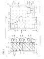
- the attachment plate 30 On attachment of the piping support 20, first, the attachment plate 30 is joined to the piping support 20 by welding. Specifically, the accessory joint face 31 of the attachment plate 30 is allowed to come into contact with an attachment face 21 which is a face on the attachment plate 30 of the piping support 20, by which a border portion between these faces 31 and 21 is joined together by welding. Connection of the attachment plate 30 with the piping support 20 may include any form of connection such as connection by welding, soldering and connecting fittings such as screws. As described previously, the piping support 20 is an H-steel member of 100 (H) x 100 (B) mm, while the attachment plate 30 is a single steel plate (400 x 200 mm). Thus, there is no chance that the attachment face 21 of the piping support 20 will run off from the accessory joint face 31 of the attachment plate 30.
- the attachment plate 30 to which the piping support 20 has been joined is joined to the outside steel plate 11 of the SC structure 10 by welding.
- the attachment plate 30 is disposed on the outside steel plate 11 of the SC structure 10 in such a manner that the piping support 20 which has been joined to the attachment plate 30 assumes an intended position on an XY plane by making the longitudinal direction of the attachment plate 30 in alignment with the Y direction.
- connection of the attachment plate 30 with the outside steel plate 11 may be carried out by welding or soldering.
- the piping support 20 is attached, for example, at the center of the attachment plate 30 (at the center in the X direction and the Y direction). As shown in the case of a in Fig. 1(b) , where the piping support 20 is positioned in the X direction on a line of a certain bar 12 and positioned in the Y direction at the center of two bars 12 adjacent in the Y direction, two bars 12 are present in a region in the X direction and the Y direction where the attachment plate 30 of the piping support 20 has been attached.
- the piping support 20 can be attached to any given position, even where the SC structure 10 receives a relatively great load from the piping support 20.
- the attachment structure of the First Embodiment is an attachment structure which is the piping support 20 with one leg.
- the attachment structure of the present embodiment is an attachment structure which is a piping support 22 with a plurality of legs.
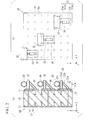
- the attachment plate 30 of the present embodiment is made to a size such that on attachment of the piping support 22, these two attachment faces 21a, 21b of the piping support 22 are both placed inside an accessory joint face 31 of the attachment plate 30, specifically, the sizes of 400 mm x 200 mm.
- the attachment plate 30 of the present embodiment is equal in sizes (400 mm x 200 mm) to the attachment plate 30 of the First Embodiment to which the piping support 20 with one leg is attached.
- the attachment plate 30 is a steel plate with sizes of 400 mm x 200 mm and a maximum length (400 mm) is twice as long as a mutual interval (200 mm) between bars 12 of the SC structure 10. It is therefore possible to attach the piping support 22 to any given position even where a load of the piping support 22 received by the SC structure 10 is relatively great.
- the present embodiment relates to a plurality of accessory attachment structures, and the plurality of accessories are all piping supports 22 as with the Second Embodiment.
- Two piping supports 22 are attached to an attachment plate 33 of the present embodiment.
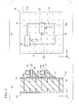
- a mutual interval dy in the Y direction between an attachment face 21a of a beam 22a of one piping support 22 and an attachment face 21a of the other piping support 22 is 450 mm, and a mutual interval dx in the X direction is 400 mm. Therefore, the attachment plate 33 of the present embodiment is made to a size such that on attachment of these two piping supports 22, the attachment faces 21a, 21b of every two piping supports 22 are both placed inside an accessory joint face 31 of the attachment plate 33, specifically, the sizes of 900 mm x 650 mm.
- a steel plate joint face 32 (900 mm x 650 mm) of the attachment plate 33 to which two piping supports 22 are attached is at least two times greater in area than a steel plate joint face 32 (400 mm x 200 mm) of the attachment plate 30 to which one piping support 22 is attached. That is, the steel plate joint face 32 is greater in area than a case where one piping support 22 is attached. It is therefore possible to increase a load of the piping support 22 received by an SC structure 10. Further, in the present embodiment, two piping supports 22 can be attached to the SC structure 10 by using one attachment plate 33 on attachment of two piping supports 22, thus making it possible to reduce man-hours necessary for attachment work.
- connection of the attachment plate 33 with the outside steel plate 11 is made, as with the embodiments so far described, by joining an outer-circumference edge of the steel plate joint face 32 of the attachment plate 33 to the outside steel plate 11 by welding.
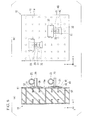
- the attachment plate 33 is relatively great in size as found in the present embodiment, it is preferable that, as shown in Fig. 4 , the outer-circumference edge of the steel plate joint face 32 of the attachment plate 33 be joined to the outside steel plate 11 and also the steel plate joint face 32 of the attachment plate 33 be joined at several spots thereinside to the outside steel plate 11 by welding.
- a through-hole 34 be formed in advance inside the attachment plate 33, and this through-hole 34 be used as a welding groove to weld the outside steel plate 11 to a part of the through-hole 34 of the attachment plate 33 (welded part 34b) and also the outer-circumference edge of the steel plate joint face 32 of the attachment plate 33 be welded to the outside steel plate 11 (welded part 34a). It is also acceptable that after the outer-circumference edge of the steel plate joint face 32 of the attachment plate 33 is welded to the outside steel plate 11, a through-hole 34 be formed inside the attachment plate 33 and the through-hole 34 be used as a welding groove to weld the outside steel plate 11 to a part of the through-hole 34 of the attachment plate 33.
- the attachment plates 30, 33 of the so far-described individual embodiments are both formed in a rectangular shape steel plate, to which the present invention shall not be, however, restricted and is fundamentally applicable to any shape.
- the attachment plate may be a regular tetragonal steel plate 35, a cross-shaped steel plate 36 or a circular steel plate 37.
- a cross-sectional shape perpendicular to the X direction of the attachment plate 38 and a cross-sectional shape perpendicular to the Y direction may be formed in the shape of an isosceles trapezoid.
- a face corresponding to an upper bottom of the isosceles trapezoid be given as an accessory joint face 31 and a face corresponding to a lower bottomof the isosceles trapezoid be given as a steel plate joint face 32.
- an attachment plate 45 which is formed by stacking a plurality of steel plates 46, 47 be used as an attachment plate for attaching a plurality of piping supports 20.
- the steel plate 46 which is closest to an accessory is installed for every plurality of piping support 20 and a face of each steel plate 46 on the side of the accessory is given as an accessory joint face 31, by which the piping support 20 is fixed to the accessory joint face 31 of each steel plate 46.
- one steel plate 47 on which the piping supports 20 fixed to the individual steel plates 46 can be disposed at the respective intended positions in the X direction and the Y direction is given as a steel plate closest to the side of the outside steel plate.
- the plurality of steel plates 46 are joined to the steel plate 47 on the side of the accessory, and a face of the steel plate 47 on the side of the outside steel plate is given as a steel plate joint face 32 and joined to the outside steel plate 11.
- an interval between the accessory joint face 31 and the steel plate joint face 32 be kept to a greater extent than a predetermined extent for the purpose of ensuring the strength against the load of the piping support 20 received by the attachment plates 38, 40, 45.
- a steel plate is used as the attachment plate, to which the present invention shall not be, however, restricted.
- Various types of plates such as a SUS plate may be used in the present invention.
- the piping support is joined to an attachment plate and the attachment plate is then joined to the outside steel plate 11. It is, however, acceptable that an attachment plate be joined to the outside steel plate 11 and the piping support be then joined to the attachment plate.
- the SC structure 201 is provided with two outside steel plates 202, a plurality of bars 203 and concrete 204.
- the outside steel plates 202 are opposed to each other to form a steel plate frame.
- the plurality of bars 203 are installed inside the steel plate frame and fixed to the steel plate frame.
- the concrete 204 is installed inside the steel plate frame.
- the bar 203 includes a tie bar 205 for connecting two outside steel plates 202 which form the steel plate frame and a stud 206 for steadily fixing the outside steel plate 202 to the concrete 204.
- a right-hand direction in Fig. 8 (a) from one outside steel plate 202 to the other outside steel plate 202 is given as the Z direction
- an upper direction in Fig. 8 perpendicular to the Z direction is given as the Y direction
- a backside direction on the page space of Fig. 8(a) perpendicular to the Z direction and the Y direction is given as the X direction.
- the pair of outside steel plates 202 are parallel to an XY plane.
- a mutual interval Ps between two studs 206 adjacent both in the X direction and the Y direction is, for example, 200 mm.
- a mutual interval Pt between two tie bars 205 adjacent both in the X direction and the Y direction is, for example, 600 mm.
- a mutual interval Pst between a stud 206 and a tie bar 205 adjacent both in the X direction and the Y direction is, for example, 200 mm. That is, in the SC structure 201, a mutual interval P between bars 203 in the X direction and the Y direction is 200 mm.
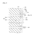
- Each tie bar 205 passes through the concrete 204 and the outside steel plate 202, and both ends thereof protrude from an outer face of the outside steel plate 202 by a predetermined length. That is, the tie bar 205 is longer than the thickness of the SC structure 201.
- the protruded length is decided depending on the thickness of an attachment plate 209 to be described later and the thickness of a nut 211 for fixing the attachment plate 209 and set so as to be at least longer than a sum of these thicknesses.
- a tie bar hole 207 for being passed through by the tie bar 205 is formed at a position corresponding to the tie bar 205 of the outside steel plate 202.
- the tie bar 205 is joined to the outside steel plate 202 by welding an inner face of the outside steel plate 202 to the tie bar 205. Thereby, an interval between the outside steel plates 202 is kept constant.
- a reference numeral 213 shown in Fig. 9 is a joint site.
- An external thread portion 220 is formed on an outer circumference of a protrusion 205a at both ends of each tie bar 205. A pitch of the external thread portion 220 is in agreement with a pitch of the nut 211 to be described later.
- the piping support 208 is attached to the outside steel plate 202 of the SC structure 201 via an attachment plate 209.
- the attachment plate 209 is formed, for example, with a single steel plate such as an SS (steel structure) material and an SM (steel marine) material.
- the attachment plate 209 is a rectangular plate-like member when viewed from above.
- One side of the attachment plate 209 is, for example, 280 mm in length.
- An attachment hole 210 is formed at each of the four corners of the attachment plate 209. The attachment holes 210 are passed by each of four protrusions 205a which are positioned so as to correspond thereto.
- the piping support 208 which is an accessory, is attached to the surface of the attachment plate 209 (hereinafter, referred to as accessory joint face 209a).
- the piping support 208 is provided with a beam 208a which directly supports a piping 225 and a reinforcing member 208b which reinforces the beam 208a.
- the beam 208a is joined, for example, by welding in such a manner that the longitudinal direction thereof is orthogonal to the accessory joint face 209a of the attachment plate 209.
- the beam 208a is joined to the accessory joint face 209a in such a manner that flanges (edges) of the beam 208a are positioned above and below.
- the reinforcing member 208b is joined so as to extend obliquely downward from a free-end lower face of the beam 208a joined to the attachment plate 209 toward the accessory joint face 209a of the attachment plate. Further, connection of the attachment plate 209 with the piping support 208 may be made in any form, for example, by welding, soldering or using connecting fittings such as screws.
- the attachment plate 209 to which the piping support 208 is joined is attached by inserting the protrusions 205a of the tie bars 205 respectively into the four attachment holes 210. Thereby, a back face of the attachment plate 209 (hereinafter, referred to as a steel plate joint face 9b) is allowed to come into contact with the outer face of the outside steel plate 202 of the SC structure 201. Further, a nut 211 is fastened to an external thread portion of the protrusion 205, by which the attachment plate 209 is fixed.
- an end of the tie bar 205 is exposed, and an external thread portion 220 which is screwed into a nut is formed at this end. Therefore, it is possible to attach the attachment plate 209 to any given tie bar 205 after visual observation is made for a site at which the tie bar 205 is installed. Further, in terms of structure, the attachment plate 209 is directly fixed to the tie bar 205. Therefore, stress resulting from a load of the piping support 208 is allowed to act on four tie bars 205 via the attachment plate 209. It is thereby possible to reduce a load received by each one of the tie bars 205. Still further, the tie bar 205 protrudes from the outer face of the outside steel plate 202. Therefore, in a step of fixing the attachment plate 209 to the SC structure 201, an attachment plate 1 may be hooked to the protrusion 205a and retained temporarily. Thereby, fixing work is done more easily.
- the attachment plate 209 can be attached to both sides of the SC structure 201, to which the present invention shall not be, however, restricted.
- the attachment plate 209 may be attached to only one side of the SC structure 201.
- the accessory attachment structure of the Fifth Embodiment is provided such that the tie bar 205 of the above-described accessory attachment structure of the Fourth Embodiment is changed in structure.
- an end face 205Aa is exposed from an outer face of an outside steel plate 202.
- the end face 205Aa is substantially flush with the outer face of the outside steel plate 202. That is, the tie bar 205A has a length which is substantially equal to the thickness of an SC structure 201A.
- An internal thread hole 214 corresponding to a bolt 212 to be described later is formed on the end face 205Aa of the tie bar 205A.
- the tie bar 205A is inserted into a tie bar hole 207 in such a manner that the end face 205Aa of the tie bar 205A is disposed to be substantially flush with the outer face of the outside steel plate 202, and an inner face of the outside steel plate 202 is welded to an outer circumferential face of the tie bar 205A to fix them.
- the internal thread hole 214 formed at the end face 205Aa of the tie bar 205A is fixed in a state of being exposed on the outer face of the outside steel plate 202.
- An attachment hole 210A of an attachment plate 209A to which a piping support 208 is attached has an inner diameter which allows the bolt 212 to pass therethrough.
- the attachment hole 210A is, as with the Fourth Embodiment, formed at a position corresponding to each of the four tie bars adjacent to each other.
- the attachment plate 209A is fixed to an SC structure 210A by screwing four bolts 212 into the internal thread holes 214 and fastening the bolts.
- the end 205Aa of the tie bar 205A is exposed on the outer face of the outside steel plate 202 and the internal thread hole 214 which is screwed with the bolt 212 is formed at the end 205Aa. It is therefore possible to attach the attachment plate 209A to any given tie bar 205A after a site at which the tie bar 205A is installed is visually observed. Further, in terms of the structure, the attachment plate 209A is directly attached to the tie bar 205A. Therefore, stress derived from a load of the piping support 208 is allowed to act on the four tie bars 205A via the attachment plate 209A. Still further, the tie bar 205A does not protrude on the outside steel plate 202. As a result, where the attachment plate 209A is not fixed, the SC structure 201A has a smoother exposed face.
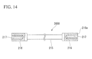
- a tie bar 205B of the present embodiment is constituted with a tie bar main body 215 and a pair of tie bar-fixing portions 216 which are joined to both ends of the tie bar main body 215.
- the tie bar main body 215 is, for example, a 36-mm-across steel rod.
- the tie bar-fixing portion 216 is, for example, a 45-mm-across steel rod and integrally welded so as to be coaxial with both ends of the tie bar main body 215.
- the integrally formed tie bar 205B has a length which is substantially equal to the thickness of an SC structure 201B.
- each of the tie bar-fixing portions 216 is formed so as to have an outer diameter greater than a tie bar hole 207B of an outside steel plate 202B.
- An internal thread hole 217 corresponding to a bolt 218 to be described later is formed at an end face 216a of the tie bar-fixing portion 216.
- the tie bar 205B is fixed to the outside steel plate 202 by screwing the bolt 218 into the internal thread hole 217 of the tie bar-fixing portion 216 in a state that the end face 216a of the tie bar-fixing portion 216 is allowed to come into contact with an inner face of an outside steel plate 202B.
- the tie bar 205B is not welded to the outside steel plate 202. Thereby, the internal thread hole 217 formed at the end face 216a of the tie bar-fixing portion 216 is exposed on an outer face of the outside steel plate 202B via the tie bar hole 207B.
- the bolt 218 which fixes the tie bar 205B corresponding to a position at which the attachment plate 209B is attached is temporarily removed. And, the attachment plate 209B is disposed on the outside steel plate 202 and again fastened and fixed by means of the bolt 218. That is, the attachment plate 209B is placed between the outside steel plate 202 and the bolt 218 and then fixed.
- a method may be used in which a pilot hole of a tapping bolt is provided to fasten and fix them by means of the tapping bolt. This method is applied to at least one side of the tie bar-fixing portion, which will not affect the positional accuracy or others of the tie bar hole 207B of the outside steel plate 202.
- the tie bar main body 215 may be integrally formed with the tie bar-fixing portion 216.
- Fig. 15 shows only one end of a tie bar 205C, both ends of the tie bar 205C are identical in shape.
- the tie bar 205C of the present embodiment is constituted with a tie bar main body 215C and a pair of tie bar-fixing portions 216C, 216C which are screwed into the both ends of the tie bar main body 215C.
- An external thread is formed at both ends of the tie bar main body 215C.
- An internal thread hole corresponding to the external thread of the tie bar main body 215C is formed at each of the tie bar-fixing portions 216. They are screwed thereinto to give an integrally formed tie bar 205C.
- the tie bar 205C is integrally formed by screwing the tie bar main body 215C into the tie bar-fixing portion 216. This will eliminate the need for a process such as welding, thus making it possible to change the length of the tie bar main body 215C more easily.
- the attachment plate may be changed in size according to the size and others of an accessory.
- a rectangular attachment plate may be attached to each of the six tie bars 205 made up of two upper and lower stages, each containing three tie bars.
- a rectangular attachment plate with two attachment holes may be attached to two tie bars 205 which are mutually adjacent.
- the attachment plate 209 is joined to the outside steel plate 202.
- the piping support 208 may be joined to the attachment plate 209.
- an accessory attachment structure 310A of the Eighth Embodiment is provided such that an attachment plate 323 of a support member 322 which supports a duct 321 (long object) is attached to an SC structure (steel plate-reinforced concrete structure) 311.
- the tie bar 315 connects the outside steel plates 312, 313, thereby keeping an interval thereof constant, irrespective of the load received from the concrete 314.
- the tie bars 315 are disposed vertically and transversely on the outside steel plates 312, 313, with a constant interval kept.
- a total of 100 tie bars 315 consisting of 10 columns in the longitudinal direction and 10 rows in the transverse direction are disposed individually so as to extend in amanner substantially orthogonal to the outside steel plates 312, 313.
- the tie bars 315 used here are identical in diameter and strength.
- the outside steel plates 312, 313 are connected with the tie bars 315 by stud welding or the like.
- plug welding is done to fix a head of the tie bar 315 to the outside steel plate 313.
- the headed tie bar 315 is melted and settled on one outside steel plate 312 by stud welding
- the other outside steel plate 313 on which a hole 313a for plug welding has been formed in advance is placed on the headed tie bar 315 and a leading end of a stud as a welding material is fused by arc stud welding to fill the hole 313a.
- a method for connecting the tie bars 315 Any method will do as long as the head of the tie bar 315 is visible (does not protrude) at least on the surface of the outside steel plate 313 to which the support member 322 is attached.
- the pair of outside steel plates 312, 313 are disposed so as to be opposed to each other, and both ends of each tie bar 315 are welded and fixed to the inner faces thereof.
- Such precast structures are produced in a large number, transported to a construction site and connected vertically and transversely.
- the concrete 314 is installed between the outside steel plates 312, 313 and the concrete 314 is hardened to complete the SC structure 311.
- the SC structure 311 is constructed mainly as an external wall, a partition wall, a floor slab (foundation slab) and the like of a building.
- subsequently attached members such as long objects including various types of machines in a building (hereinafter, a description will be given by referring to a duct 321) are installed in a state of being supported by support members (accessories) 322.
- An attachment plate 323 is attached to the surface of each of the outside steel plates 312, 313 in a region, the back side of which is provided at least with a plurality of tie bars 315.
- the tie bars 315 are disposed vertically and transversely at constant intervals in a state that a leading end of each tie bar 315 is exposed on the surface of the outside steel plate 313.
- the attachment plate 323 is mounted on a plurality of tie bars 315
- the tie bars 315 can be fixed by welding at positions where the load is taken into account.
- the duct 321 is placed for the purpose of evacuation of air at a control room of plant facilities or the like.
- the duct 321 is extended along the surface of the outside steel plate 313 in a state of being supported by support members 322.
- the duct 321 is a round duct, the cross-section of which is circular, and used is a cylindrical duct made with a relatively thin steel plate. There is no restriction on types of long objects, including, for example, a rectangular duct.
- the support member 322 is made with an H-steel member and fixed to the SC structure 311 via the attachment plate 323. Specifically, the support member 322 is composed of a beam 324 for supporting the duct 321 and a reinforcing member 325 for supporting the beam 324.
- the support member 322 may include an L-steel member and a channel bar in addition to the H-steel member.
- the attachment plate 323 is a steel plate, the shape of which is rectangular, when viewed from above.
- the attachment plate 323 is provided such that each side thereof is fixed to the surface of the outside steel plate 313 by welding.
- the attachment plate 323 is attached to a region where at least a plurality of tie bars 315 is attached. That is, the attachment plate 323 is attached to a region, the back side of outside steel plate 313 is provided with a plurality of tie bars 315.
- the attachment plate 323 is fixed to a region which is the surface of the outside steel plate 313 and where a total of four tie bars 315 composed of two columns in the longitudinal direction x 2 columns in the transverse direction are positioned on the back side thereof.
- upper and lower two H-steel members 324, 325 are disposed so as to be respectively equal in height to the tie bars 315 which are two rows in the longitudinal direction and positioned substantially at the center of the tie bars 315 which are two columns in the transverse direction.
- the attachment plate 323 is fixed to the outside steel plate 313 and positions at which the H-steel members 324, 325 are fixed to the attachment plate 323.
- design of the position can be changed, whenever necessary.
- the pair of steel plates 312, 313 are connected only by the tie bars 315. Therefore, loads of the attachment plate 323, the H-steel members 324, 325 and the duct 321 are not supported only by the outside steel plate 313 but also supported by the outside steel plate 312 and the concrete 314 via individual tie bar 315. Thereby, as compared with a case where loads of the duct 321 and others are shared by studs (not illustrated) installed on the outside steel plates 312, 313, defects and others are less likely to occur at individual portions which constitute the SC structure 311, thus making it possible to improve the strength of the SC structure 311 as a whole. It is therefore possible to attach the support member 322 to the outside steel plate 313 at any position without restriction.
- the attachment plate 323 can be fixed by welding on the basis of the tie bars 315, the heads of which are exposed on the surface. Therefore, the load of the duct 321 can be dispersed in a substantially uniform manner to the tie bars 315. Further, since heads of the tie bars 315 are exposed, in doing work for attaching the attachment plate 323 to the outside steel plate 313, the work can be done, with confirmation made for positions of the tie bars 315. It is therefore possible to perform construction in a shorter time.
- an accessory attachment structure 310B of a Ninth Embodiment is different from the accessory attachment structure 310A of the Eighth Embodiment in having a rib 316 and an inner steel plate 317. Since other constitutions are the same as those of the Eighth Embodiment, the same reference numerals are given thereto, with a description omitted here.
- the rib 316 and the inner steel plate 317 are fixed to the inner faces of the outside steel plates 312, 313, by which the outside steel plates 312, 313 can be increased in rigidity.
- the outside steel plates 312, 313 can be increased in rigidity.
- a hole for the influx of ready-mixed concrete or the like may be formed on the rib 316 and the inner face steel plate 317.
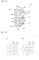
- the rib 318 is provided such that a plurality of angle bars, each of which has an L-shape cross-section, are assembled in a lattice form, and the ribs are fixed individually so as to extend all over the inner faces of the outside steel plates 312, 313. Further, as with the Ninth Embodiment, an inner steel plate 317 is installed which is fixed to the leading end of the rib 318 and disposed substantially parallel to the outside steel plates 312, 313.
- the rib 318 is assembled in a lattice form by stacking a plurality of angle bars extending in the longitudinal direction and a plurality of angle bars extending in the transverse direction in upper and lower two stages.
- the accessory attachment structure 310C of the present tenth embodiment it is possible to further ensure the strength thereof by using the L-shaped rib 318 in place of the rib 316. It is desirable that the rib 318 which extends horizontally (transversely) face upward for facilitating the influx of ready-mixed concrete. It is also desirable that a rib 318 which extends longitudinally be first installed on the back face of each of the outside steel plates 312, 313 and a rib 318 which extends transversely be then disposed so as to be overlaid on the above-described rib 318 (or via the inner face steel plate 317) in view of facilitating the influx of ready-mixed concrete.
- the edge of the rib 318 toward the other side of each of the outside steel plates 312, 313 (thickness direction) be overlaid on the tie bar 315.
- the inner steel plate 317 is installed on a rib 318 which extends transversely.
- the inner steel plate 317 may be installed between a rib 318 which extends longitudinally and a rib 318 which extends transversely or may be installed on both of them (two inner steel plates).
- one edge of an angle bar having an L-shaped cross-section is allowed to come into contact with the outside steel plates 312, 313 and be fixed. Therefore, the present embodiment is advantageous over the rib 316 of the Ninth Embodiment in that the rib 318 can be more simply and more rigidly fixed to the outside steel plates 312, 313.
- an accessory attachment structure 310D of an Eleventh Embodiment is different from the accessory attachment structures 310B, 310C of the Ninth Embodiment and Tenth Embodiment in a constitution of a rib 319. Since other constitutions are the same as those of the Ninth Embodiment and Tenth Embodiment, the same reference numerals are given to them, with a description omitted here.
- the rib 319 is provided such that a plurality of C-shaped channel bars, each of which has a C-shaped cross-section, are assembled in a lattice form.
- the ribs 319 are individually fixed so as to extend all over the inner faces of the outside steel plates 312, 313.
- an inner steel plate 317 is fixed to the leading end of the rib 319 and disposed substantially parallel to the outside steel plates 312, 313.
- the rib 319 is formed in a lattice form by stacking a plurality of angle bars extending longitudinally and a plurality of angle bars extending transversely in upper and lower two stages.
- a rib 319 extending horizontally (transversely) face its opening side toward a rib 319 extending longitudinally. It is also desirable that a rib 319 extending longitudinally be first installed on the back face of each of the outside steel plates 312, 313 and a rib 319 extending transversely be then disposed so as to be overlaid on the above-described rib 319 in view of facilitating the influx of ready-mixed concrete.
- the inner steel plate 317 is not installed on the opening side of the rib 319 extending transversely. Further, in the present embodiment, one edge of the channel bar having a C-shaped cross-section is allowed to come into contact with the outside steel plates 312, 313 and be fixed. Therefore, as with the Tenth Embodiment, the present embodiment is advantageous in fixing the rib 319 to the outside steel plates 312, 313 more simply and more rigidly.
- the support member 322 may include an L-steel member, a channel and a pipe in place of the H-beam member.
- the attachment plate 323 has a substantially square external shape when viewed from above. There is no particular restriction on the outer shape. Further, constituent features of the above-described embodiment may be replaced by known constituent features whenever necessary within a scope not departing from the gist of the present invention. Still further, the above-described embodiment may be combined in an appropriate manner.
- an SC structure (steel plate-reinforced concrete structure) 410 of the present embodiment is constituted, for example, with a steel plate frame 405, a plurality of tie bars 406, a plurality of studs 402 and concrete 401.
- the steel plate frame 405 is formed with a plurality of outside steel plates 403, 404.
- the plurality of tie bars 406 connect a pair of outside steel plates 403, 404 disposed so as to be opposed to each other in a plurality of outside steel plates 403, 404 which constitute the steel plate frame 405.
- the plurality of studs 402 are fixedly installed on an inner face of each of the outside steel plates 403, 404.
- the concrete 401 is installed inside the steel plate frame 405.
- the tie bar 406 is joined to one outside steel plate 403 of the pair of outside steel plates 403, 404.
- the other end of the tie bar 406 is joined to the other outside steel plates 404 and placed inside the steel plate frame 405 (embedded into the concrete 401).
- the studs 402 enhance connection of the outside steel plates 403, 404 with the concrete 401, etc.
- the stud 402 of the present embodiment is a headed stud equipped with a head 2b at one end of a shaft portion 402a.
- the other end of the shaft portion 402a of the stud 402 is joined to an inner face of each of the outside steel plates 403, 404 by fillet welding or the like and placed inside the steel plate frame 405 (embedded into the concrete 401).
- the SC structure 410 of the present embodiment as schematically shown in Fig. 21 (a) and Fig. 21 (b) , the plurality of studs 402 are disposed in a group.
- an accessory 407 is attached to the SC structure 410.
- the accessory 407 is a piping support 407a for supporting a piping 408.
- the piping support 407a is formed, for example, by means of an H-steel member.
- the piping support 407a is provided with an attachment plate 407b which is a steel plate.
- the attachment plate 407b is joined to the outside steel plate 403 by welding or the like and attached to the SC structure 410.
- a design system (design system of the SC structure) 420 is used to design the above-constituted SC structure 410.
- the design system 420 is provided with a structure condition input device 411, a body load-calculating device 412, reference load-calculating device 413, load ratio-calculating device 414, storage device 415, effective projection area-calculating device 416, and load-calculating device 417.
- the following idea is applied to a case where a large pull-out load is applied to one stud 402 at the center in a state that a uniform load is applied to each of the studs 402 disposed in a group (in a state shown in Fig. 27(b) ).
- the stud will be calculated for the load-bearing capacity in cone failure by using the following formula (2).
- the structure condition input device 411 is used to input the stud interval, Ps, the stud embedded depth, Le, and the stud diameter D.
- the body load-calculating device 412 is used to calculate an body load.
- the body load is a load which can be taken into account in design such as its own weight of the SC structure 410 and seismic loads excluding a load of the accessory 407.
- the reference load-calculating device 413 is used to calculate a reference load which can be supported by each one of the studs when supported by all the plurality of studs.
- the reference load is an allowable load of the stud 402.
- the reference load is a cone pull-out-bearing capacity where a plurality of studs 402 are disposed in a group, an interval between the studs 402 is narrow, and a circular area in which the embedded depth Le of each stud 402 is given as a radius is overlaid on another circular area and also where an effective projection area is rectangular.
- the reference load means how much a cone pull-out force is where the effective projection area is rectangular.
- the load ratio-calculating device 414 is used to calculate a load ratio ⁇ of the body load to the reference load. Further, with reference to a relationship between the load ratio ⁇ and the effective projection area Ac stored by the storage device 415, the effective projection area Ac is calculated from the load ratio ⁇ by using the effective projection area-calculating device 416.
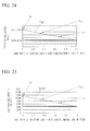
- the storage device 415 stores in advance a relationship between the load ratio and the effective projection area shown in Fig. 24 .
- the effective projection area-calculating device 416 determines a circular effective projection area Ac (Circle) by means of the formula (3) shown in Fig. 23(a) and determines a rectangular effective projection area Ac (Square) shown in Fig. 23(b) by means of the formula (4).
- the effective projection area-calculating device 416 calculates the effective projection area Ac on the basis of the respective areas obtained from the formula (3) and the formula (4) and the load ratio ⁇ of the body load to the reference load calculated by the load ratio-calculating device 414 by referring to a relationship between the load ratio ⁇ and the effective projection area Ac (formula (5)).
- Ac circle ⁇ ⁇ Le ⁇ Le + D
- Ac square Ps ⁇ Ps - ⁇ ⁇ D 2 / 4
- the load-calculating device 417 is used to calculate a load which can be supported by one stud including an accessory load.
- Fig. 25 shows results covering the load-bearing capacity of a stud preliminarily calculated by the above-described design method under the conditions that the stud interval Ps is 200 mm, the stud diameter D is 35 mm, the stud embedded depth Le is 170 mm and the concrete strength Fc is 30 MPa.
- One end of the tie bar 506 is joined to one outside steel plate 503 of the pair of outside steel plates 503, 504.
- the other end of the tie bar 506 is joined to the other outside steel plate 504 and placed inside the steel plate frame 505 (embedded into the concrete 501).
- the studs 502 enhance connection of the outside steel plates 503, 504 with the concrete 501 or others.
- the stud 502 of the present embodiment is a headed stud which is provided with a head 502b at one end of a shaft portion 502a.
- the other end of the shaft portion 502a of the stud 502 is joined to an inner face of each of the outside steel plates 503, 504 by fillet welding or the like and placed inside the steel plate frame 505 (embedded into the concrete 501).
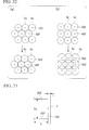
- the plurality of studs 502 arranged in a zigzag form are arranged in such a manner that three mutually adjacent studs 502 take the vertexes of an equilateral triangle, as shown in Fig. 29(b) and Fig. 30 .
- a length P of one side of the equilateral triangle is set in accordance with the length of the stud.
- the diameter of the stud is given as D and the embedded depth of the stud 502 into the concrete 501(stud length) is given as Le
- the diameter D of the stud 502 is not the diameter of the shaft portion 502a but the diameter of the head 502b.
- the circular projection planes Ac of the plurality of studs 502 are not overlaid but in contact with each other, thereby, reaching a state that the circular projection planes Ac of the plurality of studs 502 are disposed most densely in a plane of the steel plate.
- the plurality of studs 502 are disposed as described above, by which the studs are disposed uniformly and rationally all over on the surface of the SC structure 510. Further, no projection planes are overlapped between the studs, thereby eliminating the need for taking into account the effects of the studs disposed in a group on evaluation of the load-bearing capacity.
- a plurality of studs 502 are disposed so that as described above, three mutually adjacent studs 502 take the vertexes of an equilateral triangle and the plurality of studs 502 are disposed so that circular projection areas Ac are not overlaid but in contact with each other.
- the attachment plate 507b can be formed into a circular shape, the radius of which is equal to an attachment interval P between the studs 502. In this case, it is possible to transfer loads to seven studs 502 in a maximum case and three studs 502 in a minimum case.
- a plurality of studs 502 are disposed in a zigzag form, that is, disposed so that three mutually adjacent studs 502 take the vertexes of an equilateral triangle, by which circular projection areas Ac are not overlaid but in contact with each other.
- the circular projection areas Ac of mutually adjacent studs 502 on cone failure surfaces be overlaid with each other to supply the gap between the circular projection areas Ac.
- these studs 502 are to supply the gaps between the circular projection areas Ac.
- an effect obtained by increasing the stud embedded depth Le (or decreasing the stud interval Ps) in order to increase the strength of attaching the outside steel plates 503, 504 to the concrete 501 by means of the studs 502 is made greater when the studs are disposed in an equilateral triangle as described in the present embodiment than when the studs are disposed in a conventional lattice form. Therefore, the present invention is able to effectively increase the strength of attaching the outside steel plates 503, 504 to the concrete 501 by means of the studs 502.
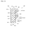
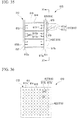
- An SC structure (steel plate-reinforced concrete structure) 610 of the present embodiment is, for example, as shown in Fig. 34 , provided with a steel plate frame 613, a plurality of tie bars 614, a plurality of studs 615, and concrete 616.
- the steel plate frame 613 is formed with a plurality of outside steel plates 611, 612.
- the plurality of tie bars 614 connect a pair of outside steel plates 611, 612 which are opposed to each other in the plurality of outside steel plates 611, 612 which form the steel plate frame 613.
- the plurality of studs 615 are fixedly installed on inner faces 611a, 612a of the respective outside steel plates 611, 612.
- the concrete 616 is installed inside the steel plate frame 613.
- the tie bar 614 is joined to one outside steel plate 611 of the pair of outside steel plates 611, 612.
- the other end of the tie bar 614 is joined to the other outside steel plate 612 and placed inside the steel plate frame 613 (embedded into the concrete 616).
- the studs 615 enhance connection of the outside steel plates 611, 612 with the concrete 616, etc.
- the stud 615 of the present embodiment is a headed stud equipped with a head 615b at one end of a shaft portion 615a.
- the other end of the shaft portion 615a of the stud 615 is joined to the inner face 611a or 612b of the outside steel plate 611 or 612 by fillet welding or the like and placed inside the steel plate frame 613 (embedded into the concrete 616).
- a plurality of studs 615 are arranged and disposed on the inner faces 611a, 612a of the outside steel plates 611, 612 and fixedly installed thereon. Further, on the outside steel plate 611, a center position surrounded by four studs 615 (and tie bars 614) thus arranged and disposed is given as an attachment position to which the accessory 617 can be attached. Still further, a locking portion 620 is installed at a plurality of attachment positions to which the accessories 617 are attached on the outer face 611b of the outside steel plate 611.
- the locking portion 620 of the present embodiment is an engagement recess portion (recess) with which a raised portion 619 formed on an attachment face of the attachment plate 617b is engaged.
- the attachment plate 617b and the piping support 617a are locked by the locking portion 620.
- the attachment device 618 is made up of the raised portion 619 and the locking portion 620 having an engagement recess portion.
- the raised portion 619 of the accessory 617 is selectively locked to any of the plurality of locking portions 620 installed at each of the plurality of attachment positions, by which the accessory 617 is fixed onto the outer face 611b of the outside steel plate 611.
- the accessory 617 having the attachment plate 617b and the piping support 617a is fixed and attached to the outer face 611b of the outside steel plate 611 (accessory-fixing step).
- the raised portion 619 installed on the attachment plate 617b is selectively engaged with any of the engagement recess portions of the locking portion 620 installed at the plurality of attachment positions on the outer face 611b of the outside steel plate 611, by which the accessory 617 is locked.
- the attachment plate 617b is fixed to the outer face 611b of the outside steel plate 611 by welding.
- a piping 602 is installed on the piping support 617a of the accessory 617 (piping-installing step). Thereby, the accessory 618 is attached to the outer face 611b of the outside steel plate 611 and construction is completed.
- At the attachment device-preparing step at least the locking portion 620 (engagement recess portion) or the part of the attachment device 618 is disposed at the plurality of attachment positions on the outer face 611b of the outside steel plate 611 to which the accessory 617 can be attached. Therefore, at least a part of the attachment device 618 can be disposed, while the position of the stud 615 can be confirmed easily.
- the raised portion 619 of the attachment plate 617b of the accessory 617 is engaged with the engagement recess portion of the locking portion 620 to attach the accessory 617.
- the accessory 617 can be attached, with confirmation given to the position of the stud 615. It is therefore possible to attach and construct the accessory 617, while a load applied to each one of the studs can reliably be kept low.
- the attachment device-preparing step at least a part of the attachment device 618 is disposed at the plurality of attachment positions on the outer face 611b of the outside steel plate 611 to which the accessory 617 can be attached. It is therefore possible to dispose at least a part of the attachment device 618, while the position of the stud 615 can be confirmed easily.
- the piping-installing step on installation of the piping 602 on the accessory 617, the piping 602 can be attached and constructed, while a load applied to each one of the studs is reliably kept low.
- the raised portion 619 of the accessory 617 is selectively locked to any of the locking portions 620 install ed at the plurality of attachment positions on the outer face 611b of the outside steel plate 611. Therefore, it is possible to attach the accessory 617 to the outer face 611b of the outside steel plate 611 via the attachment device 618. Thereby, such a simple procedure is carried out that the plurality of attachment positions at which a load applied to each one of the studs can be kept low are set and the raised portion 619 of the main body 617 is locked to the locking portion 620 installed at the attachment position, thus making it possible to attach and construct the accessory 617 while the load applied to each one of the studs is reliably kept low.
- the raised portion 619 of the accessory 617 can be selectively locked to any of the locking portions 620 installed at the plurality of attachment positions on the outer face 611b of the outside steel plate 611. It is therefore possible to attach the accessory 617 to any given attachment position.
- a plurality of studs 615 be fixedly installed on inner faces 611a, 612a of the outside steel plates 611, 612, and the piping support 617a (accessory 617) be fixed and attached by welding or the like to a plurality of attachment positions on the outer face 611b of the outside steel plate 611.
- the accessory 617 it is possible to attach and construct the accessory 617, while a load applied to each one of the studs is reliably kept low. Further, as compared with a conventional case, it is possible to reduce the time necessary for constructing the accessory 617 and the time necessary for designing the attachment position of the accessory.
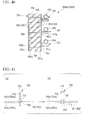
- An SC structure (steel plate-reinforced concrete structure) 709A of the present embodiment is, for example as shown in Fig. 40 , provided with a steel plate frame 703, a plurality of tie bars 704, a plurality of studs 705, and concrete 706.
- the steel plate frame 703 is formed with a plurality of outside steel plates 701, 702.
- the plurality of tie bars 704 connect one pair of outside steel plates 701, 702 which are opposed to each other in the plurality of outside steel plates 701, 702 which constitute the steel plate frame 703.
- the plurality of studs 705 are fixedly installed on an inner face of each of the outside steel plates 701, 702.
- the concrete 706 is installed inside the steel plate frame 703.
- an accessory 707 is attached to the SC structure 709A.
- the accessory 707 is a piping support 707a for supporting a piping 708.
- the piping support 707a is formed, for example, by using an H-steel member.
- the piping support 707a of the accessory 707 is provided with an attachment plate (attachment plate) 707b which is a steel plate.
- the attachment plate 707b is joined to the outside steel plate 701 by welding or the like. Thereby, the accessory 707 is attached to the SC structure 709A.
- One end of the tie bar 704 of the SC structure 709A is joined to one outside steel plate 701 of the pair of outside steel plate 701, 702.
- the other end of the tie bar 704 is joined to the other outside steel plate 702 and placed inside the steel plate frame 703 (embedded into the concrete 706).
- the studs 705 enhance connection of the outside steel plates 701, 702 with the concrete 706, etc.
- the studs 705 are fixed to the outside steel plates 701, 702 and installed so as to protrude into the steel plate frame 703.
- the stud 705 of the present embodiment is provided with a cylindrical shaft portion 710, a first holding portion (the other holding portion) 711 and a head 712, as shown in Fig. 41(a) .
- the first holding portion 711 is placed to the other side only by a predetermined length from one side of the shaft portion 710 which is fixed to the outside steel plate 701 (702) and formed integrally.
- the head 712 is integrally formed on the other side of the shaft portion 710.
- first holding portion 711 and the head 712 are respectively formed in the shape of a circular plate, for example.
- the first holding portion 711 and the head 712 are placed in such a manner that their respective center axes are made coaxial with the shaft portion 710 and the outer-circumference edge is allowed to protrude radically outward from an outer circumference face of the shaft portion 710.
- a through-hole 713 which pass through from an inner face 701a (702a) to an outer face 701b (702b) is formed at a predetermined position of the outside steel plate 701 (702) to which the stud 705 is attached.
- the SC structure 709A of the present embodiment as shown in Fig. 41 (a) , one side of the shaft portion 710 is inserted through the through-hole 713 of the outside steel plate 701 (702) and the first holding portion 711 is allowed to come into contact with the inner face 701a (702a) of the outside steel plate 701 (702), thereby placing the stud 705.
- Fig. 41 (a) one side of the shaft portion 710 is inserted through the through-hole 713 of the outside steel plate 701 (702) and the first holding portion 711 is allowed to come into contact with the inner face 701a (702a) of the outside steel plate 701 (702), thereby placing the stud 705.
- one side (end) of the shaft portion 710 protruding beyond the through-hole 713 outside from the outer face 701b (702b) of the outside steel plate 701 (702) is collapsed to form a second holding portion (one holding portion) 714, which is then crimped.
- one pair of holding portions 711, 714 are used to hold the outside steel plate 701 (702) between them, by which the stud 705 is fixed to a predetermined position of the outside steel plate 701 (702) in a manner similar to a rivet structure.
- the studs 705 be constructed by being attached to the outside steel plates 701, 702 with use of an AR machine (automatic studding machine, automatic riveter) in a modified manner.
- an ARmachine 715 is, for example, provided with a positioning portion 716 and an AR main body 717.
- the positioning portion 716 retains the outside steel plates 701, 702 and also positions them.
- the AR main body 717 attaches studs 705 to the outside steel plates 701, 702.
- the positioning portion 716 is actuated on the basis of triaxial translation (forward and backward movement along the X axis, the Y axis and the Z axis) and biaxial rotation of A axis (around the X axis) and B axis (around the Y axis; movement by a difference in height between the Z axis and the W axis).
- triaxial translation forward and backward movement along the X axis, the Y axis and the Z axis
- the AR main body 717 is provided with a cutter head 718 and a working head 719.
- the cutter head 718 drills a through-hole 713 at a predetermined position of the outside steel plate 701, 702 decided by the positioning portion 716.
- the working head 719 attaches the studs 705 to the outside steel plates 701, 702.
- positions at which the studs 705 are attached to the outside steel plate 701 (702) are stored in an NC machine.
- the outside steel plate 701 (702) is set on the positioning portion 716 to start construction. Thereby, the positioning portion 716 is actuated to place the outside steel plate 701 (702) at a predetermined position.
- the NC controlled cutter head 718 is used to drill the through-hole 713 at a position to which the outside steel plate 701 (702) is attached by the stud.
- Fig. 42 and Fig. 43(a) the outside steel plate 701 (702) is set on the positioning portion 716 to start construction. Thereby, the positioning portion 716 is actuated to place the outside steel plate 701 (702) at a predetermined position.
- the NC controlled cutter head 718 is used to drill the through-hole 713 at a position to which the outside steel plate 701 (702) is attached by the stud.
- the working head 719 retains the stud 705 and inserts one end of the shaft portion 710 into the through-hole 713.
- one end of the shaft portion 710 is crimped to form a second holding portion 714.
- the AR machine 715 can be used to attach the studs 705 automatically and rationally to the outside steel plates 701, 702. Further, as compared with a conventional case where the studs 705 are fixed to the outside steel plates 701, 702 by welding, it is possible to reduce man-hours necessary for constructing the studs and also reduce the construction cost.
- each stud 720 is constituted with a bolt 721 and three nuts 722, 723, 724.
- a through-hole 713 is formed at a predetermined position of an outside steel plate 701 (702) to which the stud 720 is attached.
- a shaft portion 721a of the bolt 721 of the stud 720 is inserted through the through-hole 713 from an outer face 701b (702b) of the outside steel plate 701 (702), by which the head 721b of the bolt 721 is allowed to come into contact with the outer face 701b (702b) of the outside steel plate 701 (702).
- the first nut 722 is screwed into the shaft portion 721a of the bolt 721 which protrudes to the inner face 701a (702a) of the outside steel plate 701 (702).
- the head 721b of the bolt 721 (a second holding portion, one holding portion) and the first nut 722 (first holding portion, the other holding portion) are given as a pair of holding portions 721b, 722, thereby holding the outside steel plate 701 (702) between them.
- the stud 720 is fixed to the outside steel plate 701 (702) by the head 721b of the bolt 721 and the first nut 722.
- the third nut 724 is screwed into the shaft portion 721a of the bolt 721. At this time, the third nut 724 is placed on the other side of the shaft portion 721a of the bolt 721.
- the stud 720 of the present embodiment has a head at the other end by the third nut 724 and formed like a headed stud.
- the stud 720 is made up of the bolt 721 and the nuts 722, 723, 724.
- the shaft portion 721a of the bolt 721 is inserted through the through-hole 713 on the outside steel plate 701 (702) to fasten the nut 722, by which the head 721b of the bolt 721 and the nut 722 are given as a pair of holding portions and hold the outside steel plate 701 (702) between them.
- the stud 720 can be fixed to the SC structure 709B.
- the SC structure 709B of the present embodiment as compared with a conventional case where a stud is fixed to the outside steel plate by welding, it is possible to reduce man-hours for constructing the stud and also reduce the construction costs.
- the outside steel plate 701 (702) is held between a pair of holding portions, that is, the head 721b of the bolt 721 and the nut 722 and fixed by the stud 720 of the SC structure 709B. Therefore, it is possible to locate a position of the stud 720 from outside of the outside steel plate 701 (702) by means of the head 721b of the bolt 721 which is a second holding portion installed on an outer face 701b (702b) of the outside steel plate 701 (702) on attachment of an accessory 707.
- the position of the stud 720 can be easily located by means of one holding portion 721b on attachment of the accessory 707. Therefore, it is possible to reduce the time necessary for constructing the accessory 707 and also the time necessary for designing an attachment position of the accessory 707.
- the head 721b of the bolt 721 of the stud 720 at the second holding portion can be placed into the recess portion 725. It is, thereby, possible to prevent formation of irregularities on the outer face 701b (702b) of the outside steel plate 701 (702) by the second holding portion 721b.
- the present invention is able to reduce a load which is applied to each one of the bars.
- the accessory can be attached to any given position.
- stress resulting from the load of the accessory is allowed to act on a tie bar via an attachment plate. Further, it is possible to easily locate an attachment position of the accessory and reduce a load applied to each one of the tie bars on attachment of the accessory,
- a stud in the design system of the SC structure and the design method of the SC structure of the present invention, as compared with a conventional design method of the SC structure, a stud can be evaluated rationally for the load-bearing capacity thereof by reviewing a method determining an effective projection area in cone failure.
- a plurality of studs are provided by being arranged in a zigzag form, thus making it possible to evaluate each of the studs as an independent stud.
- the stud can be evaluated rationally for the load-bearing capacity, as compared with a case where a plurality of studs are arranged and disposed vertically and transversely (where they are arranged in a lattice form).
- the construction method of the SC structure and the SC structure of the present invention it is possible to set a plurality of attachment positions at which a load applied to each one of the studs can be kept low while a position of the stud is easily confirmed and also attachment device can be installed at the attachment position. It is thereby possible to attach and construct an accessory in a state that a load applied to each one of the studs is reliably kept low. As compared with a conventional case, it is possible to reduce the time necessary for constructing the accessory and also the time necessary for designing the attachment position of the accessory.
- a shaft portion is inserted through a through-hole formed on an outside steel plate, and a pair of holding portions installed integrally at this shaft portion are used to hold the outside steel plate between them, thereby fixing a stud. It is therefore possible to locate a position of the stud from outside of the outside steel plate by means of one holding portion installed on an outer face of the outside steel plate. Accordingly, on attachment of an accessory, a position of the stud can be easily located by means of one holding portion. It is therefore possible to reduce the time necessary for constructing the accessory and also the time necessary for designing an attachment position of the accessory.
Landscapes
- Engineering & Computer Science (AREA)
- Architecture (AREA)
- Physics & Mathematics (AREA)
- Electromagnetism (AREA)
- Civil Engineering (AREA)
- Structural Engineering (AREA)
- General Engineering & Computer Science (AREA)
- Mechanical Engineering (AREA)
- Joining Of Building Structures In Genera (AREA)
Applications Claiming Priority (8)
| Application Number | Priority Date | Filing Date | Title |
|---|---|---|---|
| JP2010213808A JP5713618B2 (ja) | 2010-09-24 | 2010-09-24 | 付帯物の取付構造 |
| JP2010235468A JP2012087538A (ja) | 2010-10-20 | 2010-10-20 | 付帯物の取付構造 |
| JP2010280561A JP5843440B2 (ja) | 2010-12-16 | 2010-12-16 | サポート取り付け構造 |
| JP2011040007A JP5773684B2 (ja) | 2011-02-25 | 2011-02-25 | 鋼板コンクリート構造の施工方法 |
| JP2011040004A JP5751862B2 (ja) | 2011-02-25 | 2011-02-25 | 鋼板コンクリート構造の設計システム及び鋼板コンクリート構造の設計方法 |
| JP2011040009A JP5791306B2 (ja) | 2011-02-25 | 2011-02-25 | 鋼板コンクリート構造 |
| JP2011040006A JP5791305B2 (ja) | 2011-02-25 | 2011-02-25 | 鋼板コンクリート構造 |
| PCT/JP2011/070552 WO2012039295A1 (ja) | 2010-09-24 | 2011-09-09 | 付帯物の取付構造、sc構造の設計システム及び設計方法、sc構造の施工方法、及びsc構造 |
Publications (2)
| Publication Number | Publication Date |
|---|---|
| EP2620563A1 true EP2620563A1 (de) | 2013-07-31 |
| EP2620563A4 EP2620563A4 (de) | 2014-07-16 |
Family
ID=45873784
Family Applications (1)
| Application Number | Title | Priority Date | Filing Date |
|---|---|---|---|
| EP20110826741 Withdrawn EP2620563A4 (de) | 2010-09-24 | 2011-09-09 | Zubehörbefestigungsstruktur, verfahren und system zum entwurf einer durch eine stahlplatte verstärkten betonstruktur, verfahren zur konstruktion der durch eine stahlplatte verstärkten betonstruktur und durch eine stahlplatte verstärkte betonstruktur |
Country Status (3)
| Country | Link |
|---|---|
| US (1) | US20190195255A1 (de) |
| EP (1) | EP2620563A4 (de) |
| WO (1) | WO2012039295A1 (de) |
Cited By (1)
| Publication number | Priority date | Publication date | Assignee | Title |
|---|---|---|---|---|
| CN103835411A (zh) * | 2014-01-23 | 2014-06-04 | 浙江杭萧钢构股份有限公司 | 一种钢板混凝土组合剪力墙 |
Families Citing this family (3)
| Publication number | Priority date | Publication date | Assignee | Title |
|---|---|---|---|---|
| JP6980372B2 (ja) * | 2016-09-20 | 2021-12-15 | ナカ工業株式会社 | エキスパンションジョイントカバーの敷設構造 |
| CN110344373B (zh) * | 2019-07-29 | 2024-02-20 | 中水淮河规划设计研究有限公司 | 一种堵头式橡胶坝不锈钢抗磨损衬板的安装方法 |
| US20220145619A1 (en) * | 2020-11-06 | 2022-05-12 | Nelson Stud Welding, Inc. | Concrete wall frame assembly and method of manufacturing same |
Family Cites Families (42)
| Publication number | Priority date | Publication date | Assignee | Title |
|---|---|---|---|---|
| US1852049A (en) * | 1931-04-14 | 1932-04-05 | Russell C Graef | Building construction |
| US2062724A (en) * | 1935-02-20 | 1936-12-01 | Alfred G Olsen | Permanent metallic form for concrete building structures |
| US2303837A (en) * | 1941-04-30 | 1942-12-01 | Gurber Samuel | Building construction |
| US3751867A (en) * | 1971-12-03 | 1973-08-14 | Raymond Lee Organization Inc | Panel to form composite concrete-reinforced wall |
| US4107893A (en) * | 1972-05-13 | 1978-08-22 | Rensch Eberhard | Prefabricated building structure |
| US4426061A (en) * | 1980-08-04 | 1984-01-17 | Taggart John R | Method and apparatus for forming insulated walls |
| JPS6047140A (ja) * | 1983-08-23 | 1985-03-14 | 三菱重工業株式会社 | 鋼板コンクリ−ト構造物 |
| US4669234A (en) * | 1985-03-18 | 1987-06-02 | Wilnau John A | Prefabricated wall section |
| JP2501910Y2 (ja) * | 1990-09-17 | 1996-06-19 | 石川島播磨重工業株式会社 | 原子炉格納容器の貫通部構造 |
| US5092093A (en) * | 1990-12-31 | 1992-03-03 | Lu Shin Yuang | Panel forms having panel reinforcing means |
| TW299381B (de) * | 1991-08-13 | 1997-03-01 | Mitsubishi Heavy Ind Ltd | |
| JPH0557130U (ja) * | 1992-01-17 | 1993-07-30 | 日本フエラス工業株式会社 | コンクリート型枠 |
| JP2751705B2 (ja) * | 1992-01-21 | 1998-05-18 | 鹿島建設株式会社 | 鋼板コンクリート構造物の解体方法 |
| JP2611090B2 (ja) * | 1992-06-09 | 1997-05-21 | 大和ハウス工業株式会社 | 角形鋼管柱の柱脚構造 |
| US5375809A (en) * | 1992-07-01 | 1994-12-27 | Wallace I. Stenzel | Assembly for forming a poured concrete wall construction |
| JP3624387B2 (ja) * | 1995-06-08 | 2005-03-02 | 日本ドライブイット株式会社 | 鋼板間にスペーサを溶接する方法 |
| US5809725A (en) * | 1995-07-18 | 1998-09-22 | Plastedil S.A. | Sectional nog structure for fastening a covering element to a foamed plastic slab and construction element incorporating said structure |
| JP2750846B2 (ja) * | 1995-08-30 | 1998-05-13 | 義行 早川 | コンクリート型枠対向間隔保持固定用具 |
| JPH09287204A (ja) * | 1996-04-24 | 1997-11-04 | Mitsubishi Heavy Ind Ltd | 塗布材料の定着用鉄筋装置 |
| JPH10160881A (ja) * | 1996-11-29 | 1998-06-19 | Toshiba Corp | 原子力発電所の建屋構造および建屋建築工法 |
| US6041561A (en) * | 1997-08-22 | 2000-03-28 | Wayne Leblang | Self-contained molded pre-fabricated building panel and method of making the same |
| US5895188A (en) * | 1997-09-03 | 1999-04-20 | Cheng; Tsan-Hsiung | Form panel quick fastener |
| JP2000240196A (ja) * | 1999-02-23 | 2000-09-05 | Kajima Corp | 鋼板コンクリート構造のタイバー取付方法およびタイバー |
| JP2001248246A (ja) | 2000-03-06 | 2001-09-14 | Mitsubishi Heavy Ind Ltd | 鋼板コンクリート構造 |
| JP4220120B2 (ja) * | 2000-12-12 | 2009-02-04 | 株式会社東芝 | 水圧制御ユニットおよびその据付け方法 |
| JP4016382B2 (ja) | 2002-05-09 | 2007-12-05 | 東芝プラントシステム株式会社 | Sc構造体への電設工法 |
| US7124547B2 (en) * | 2002-08-26 | 2006-10-24 | Bravinski Leonid G | 3-D construction modules |
| US7934693B2 (en) * | 2003-11-25 | 2011-05-03 | Bravinski Leonid G | Formwork for erecting reinforced concrete walls, including concrete walls with textured surfaces |
| JP2006009244A (ja) * | 2004-06-22 | 2006-01-12 | Hitachi Ltd | 鋼板コンクリート構造物及びその構築方法 |
| JP2007046305A (ja) * | 2005-08-09 | 2007-02-22 | Hitachi Ltd | Sc造構造体用取付金物 |
| JP4813893B2 (ja) | 2005-12-20 | 2011-11-09 | 株式会社大林組 | 付着応力度の算出方法、スタッドのせん断力の算出方法、設計方法、鋼板コンクリート構造物 |
| KR100849711B1 (ko) * | 2007-06-27 | 2008-08-01 | 한국수력원자력 주식회사 | 강판 구조체 및 강판 콘크리트 벽체 |
| JP4625115B2 (ja) | 2007-11-13 | 2011-02-02 | パナソニック株式会社 | ランプ用ガラス組成物、ランプ用ガラス部品、ランプ及び照明装置 |
| US20090282753A1 (en) * | 2008-05-19 | 2009-11-19 | Chin-Lu Kuan | Shock-Resisting Steel Concrete Structure |
| WO2010003211A1 (en) * | 2008-07-11 | 2010-01-14 | Saulro Inc. | Panel interlocking system |
| JP5143797B2 (ja) | 2009-08-18 | 2013-02-13 | 株式会社高速屋 | ビット列データソート装置、ソート方法及びプログラム |
| JP5665275B2 (ja) * | 2009-02-04 | 2015-02-04 | 三菱重工業株式会社 | 原子炉格納容器の壁体および原子炉格納容器の壁体建造方法 |
| JP2010213808A (ja) | 2009-03-16 | 2010-09-30 | Daikoku Denki Co Ltd | スロットマシン |
| JP2010235468A (ja) | 2009-03-30 | 2010-10-21 | Uha Mikakuto Co Ltd | Lox−1アンタゴニスト作用を高活性に有する味の品質が確保されたバナバエキス |
| JP2011040004A (ja) | 2009-08-18 | 2011-02-24 | Sony Corp | 画像処理装置及び画像処理方法 |
| JP2011040006A (ja) | 2009-08-18 | 2011-02-24 | Mega Chips Corp | 管理システム及び検知装置 |
| JP5629438B2 (ja) | 2009-08-18 | 2014-11-19 | キヤノン株式会社 | ファイル管理装置及びその制御方法 |
-
2011
- 2011-09-09 US US13/824,847 patent/US20190195255A1/en not_active Abandoned
- 2011-09-09 WO PCT/JP2011/070552 patent/WO2012039295A1/ja not_active Ceased
- 2011-09-09 EP EP20110826741 patent/EP2620563A4/de not_active Withdrawn
Cited By (1)
| Publication number | Priority date | Publication date | Assignee | Title |
|---|---|---|---|---|
| CN103835411A (zh) * | 2014-01-23 | 2014-06-04 | 浙江杭萧钢构股份有限公司 | 一种钢板混凝土组合剪力墙 |
Also Published As
| Publication number | Publication date |
|---|---|
| US20190195255A1 (en) | 2019-06-27 |
| EP2620563A4 (de) | 2014-07-16 |
| WO2012039295A1 (ja) | 2012-03-29 |
Similar Documents
| Publication | Publication Date | Title |
|---|---|---|
| US10407911B2 (en) | Multi-purpose anchor devices | |
| EP2620563A1 (de) | Zubehörbefestigungsstruktur, verfahren und system zum entwurf einer durch eine stahlplatte verstärkten betonstruktur, verfahren zur konstruktion der durch eine stahlplatte verstärkten betonstruktur und durch eine stahlplatte verstärkte betonstruktur | |
| KR101745835B1 (ko) | 용접 연결부를 구비한 거더 및 그 시공 방법 | |
| KR102204901B1 (ko) | 강판 보강 전단벽 | |
| JP2010024747A (ja) | 山形鋼部材の座屈補強方法及び当該方法において使用する補強具 | |
| JP7670753B2 (ja) | 梁の構造、梁主筋配筋用の支持部材、および梁主筋の配筋方法 | |
| JP2003184184A (ja) | 建物ユニットの接合構造および接合方法 | |
| KR102167960B1 (ko) | 구조 개선된 보강구조물이 적용된 교량용 강관 거더 | |
| US20150027076A1 (en) | Sleeve Device For Increasing Shear Capacity | |
| JP4028831B2 (ja) | 取り外し可能支保工梁 | |
| JP7831949B2 (ja) | 仕上げ材取付用パネルおよび建物 | |
| JP2009133114A (ja) | 壁付き柱部材の補強構造 | |
| JP2002201612A (ja) | 架設鋼材定着用治具 | |
| US8590230B2 (en) | Prestressed slab element | |
| EP2402526A1 (de) | Bauteil einer gebäudeeinheit und bodenstruktur mit diesem bauteil | |
| CN217079807U (zh) | 楼面洞口防护盖板 | |
| CN216640902U (zh) | 预制主次梁钢筋互锚连接节点装置 | |
| JP4842093B2 (ja) | フラットプレート構築方法 | |
| CN222923955U (zh) | 一种钢筋密布部位设有分体式预埋铁件的剪力墙 | |
| JP2008007950A (ja) | 埋込金具とプレキャストコンクリート部材 | |
| JP2008007949A (ja) | プレキャストコンクリート製の柱又は壁と梁との架構システム | |
| JP7781155B2 (ja) | 補強モジュール式スチール・コンクリート構造体 | |
| JP2000120166A (ja) | プレキャストコンクリート製柱、及びプレキャストコンクリート製の柱と梁の接合構造体。 | |
| JP4235080B2 (ja) | プレキャストコンクリート部材の接合構造 | |
| JP7098398B2 (ja) | 連結構造 |
Legal Events
| Date | Code | Title | Description |
|---|---|---|---|
| PUAI | Public reference made under article 153(3) epc to a published international application that has entered the european phase |
Free format text: ORIGINAL CODE: 0009012 |
|
| 17P | Request for examination filed |
Effective date: 20130322 |
|
| AK | Designated contracting states |
Kind code of ref document: A1 Designated state(s): AL AT BE BG CH CY CZ DE DK EE ES FI FR GB GR HR HU IE IS IT LI LT LU LV MC MK MT NL NO PL PT RO RS SE SI SK SM TR |
|
| DAX | Request for extension of the european patent (deleted) | ||
| A4 | Supplementary search report drawn up and despatched |
Effective date: 20140613 |
|
| RIC1 | Information provided on ipc code assigned before grant |
Ipc: G21C 13/00 20060101ALI20140606BHEP Ipc: E04B 1/48 20060101ALI20140606BHEP Ipc: E04B 1/30 20060101ALI20140606BHEP Ipc: E04B 2/86 20060101ALI20140606BHEP Ipc: E04B 1/14 20060101AFI20140606BHEP Ipc: F16B 9/02 20060101ALI20140606BHEP Ipc: E04B 1/16 20060101ALI20140606BHEP |
|
| 17Q | First examination report despatched |
Effective date: 20150424 |
|
| GRAP | Despatch of communication of intention to grant a patent |
Free format text: ORIGINAL CODE: EPIDOSNIGR1 |
|
| INTG | Intention to grant announced |
Effective date: 20160419 |
|
| STAA | Information on the status of an ep patent application or granted ep patent |
Free format text: STATUS: THE APPLICATION IS DEEMED TO BE WITHDRAWN |
|
| 18D | Application deemed to be withdrawn |
Effective date: 20160830 |