EP2620983B1 - Halbleiterelement und herstellungsverfahren dafür - Google Patents
Halbleiterelement und herstellungsverfahren dafür Download PDFInfo
- Publication number
- EP2620983B1 EP2620983B1 EP11835849.8A EP11835849A EP2620983B1 EP 2620983 B1 EP2620983 B1 EP 2620983B1 EP 11835849 A EP11835849 A EP 11835849A EP 2620983 B1 EP2620983 B1 EP 2620983B1
- Authority
- EP
- European Patent Office
- Prior art keywords
- region
- silicon carbide
- semiconductor layer
- concentration
- semiconductor element
- Prior art date
- Legal status (The legal status is an assumption and is not a legal conclusion. Google has not performed a legal analysis and makes no representation as to the accuracy of the status listed.)
- Active
Links
Images


Classifications
-
- H—ELECTRICITY
- H10—SEMICONDUCTOR DEVICES; ELECTRIC SOLID-STATE DEVICES NOT OTHERWISE PROVIDED FOR
- H10P—GENERIC PROCESSES OR APPARATUS FOR THE MANUFACTURE OR TREATMENT OF DEVICES COVERED BY CLASS H10
- H10P30/00—Ion implantation into wafers, substrates or parts of devices
- H10P30/20—Ion implantation into wafers, substrates or parts of devices into semiconductor materials, e.g. for doping
- H10P30/202—Ion implantation into wafers, substrates or parts of devices into semiconductor materials, e.g. for doping characterised by the semiconductor materials
- H10P30/204—Ion implantation into wafers, substrates or parts of devices into semiconductor materials, e.g. for doping characterised by the semiconductor materials into Group IV semiconductors
-
- H—ELECTRICITY
- H10—SEMICONDUCTOR DEVICES; ELECTRIC SOLID-STATE DEVICES NOT OTHERWISE PROVIDED FOR
- H10D—INORGANIC ELECTRIC SEMICONDUCTOR DEVICES
- H10D12/00—Bipolar devices controlled by the field effect, e.g. insulated-gate bipolar transistors [IGBT]
- H10D12/01—Manufacture or treatment
- H10D12/031—Manufacture or treatment of IGBTs
-
- H—ELECTRICITY
- H10—SEMICONDUCTOR DEVICES; ELECTRIC SOLID-STATE DEVICES NOT OTHERWISE PROVIDED FOR
- H10D—INORGANIC ELECTRIC SEMICONDUCTOR DEVICES
- H10D30/00—Field-effect transistors [FET]
- H10D30/01—Manufacture or treatment
- H10D30/021—Manufacture or treatment of FETs having insulated gates [IGFET]
- H10D30/028—Manufacture or treatment of FETs having insulated gates [IGFET] of double-diffused metal oxide semiconductor [DMOS] FETs
- H10D30/0291—Manufacture or treatment of FETs having insulated gates [IGFET] of double-diffused metal oxide semiconductor [DMOS] FETs of vertical DMOS [VDMOS] FETs
-
- H—ELECTRICITY
- H10—SEMICONDUCTOR DEVICES; ELECTRIC SOLID-STATE DEVICES NOT OTHERWISE PROVIDED FOR
- H10D—INORGANIC ELECTRIC SEMICONDUCTOR DEVICES
- H10D30/00—Field-effect transistors [FET]
- H10D30/60—Insulated-gate field-effect transistors [IGFET]
- H10D30/63—Vertical IGFETs
- H10D30/635—Vertical IGFETs having no inversion channels, e.g. vertical accumulation channel FETs [ACCUFET] or normally-on vertical IGFETs
-
- H—ELECTRICITY
- H10—SEMICONDUCTOR DEVICES; ELECTRIC SOLID-STATE DEVICES NOT OTHERWISE PROVIDED FOR
- H10D—INORGANIC ELECTRIC SEMICONDUCTOR DEVICES
- H10D62/00—Semiconductor bodies, or regions thereof, of devices having potential barriers
- H10D62/80—Semiconductor bodies, or regions thereof, of devices having potential barriers characterised by the materials
- H10D62/83—Semiconductor bodies, or regions thereof, of devices having potential barriers characterised by the materials being Group IV materials, e.g. B-doped Si or undoped Ge
- H10D62/832—Semiconductor bodies, or regions thereof, of devices having potential barriers characterised by the materials being Group IV materials, e.g. B-doped Si or undoped Ge being Group IV materials comprising two or more elements, e.g. SiGe
- H10D62/8325—Silicon carbide
-
- H—ELECTRICITY
- H10—SEMICONDUCTOR DEVICES; ELECTRIC SOLID-STATE DEVICES NOT OTHERWISE PROVIDED FOR
- H10P—GENERIC PROCESSES OR APPARATUS FOR THE MANUFACTURE OR TREATMENT OF DEVICES COVERED BY CLASS H10
- H10P30/00—Ion implantation into wafers, substrates or parts of devices
- H10P30/20—Ion implantation into wafers, substrates or parts of devices into semiconductor materials, e.g. for doping
- H10P30/202—Ion implantation into wafers, substrates or parts of devices into semiconductor materials, e.g. for doping characterised by the semiconductor materials
- H10P30/204—Ion implantation into wafers, substrates or parts of devices into semiconductor materials, e.g. for doping characterised by the semiconductor materials into Group IV semiconductors
- H10P30/2042—Ion implantation into wafers, substrates or parts of devices into semiconductor materials, e.g. for doping characterised by the semiconductor materials into Group IV semiconductors into crystalline silicon carbide
-
- H—ELECTRICITY
- H10—SEMICONDUCTOR DEVICES; ELECTRIC SOLID-STATE DEVICES NOT OTHERWISE PROVIDED FOR
- H10P—GENERIC PROCESSES OR APPARATUS FOR THE MANUFACTURE OR TREATMENT OF DEVICES COVERED BY CLASS H10
- H10P30/00—Ion implantation into wafers, substrates or parts of devices
- H10P30/20—Ion implantation into wafers, substrates or parts of devices into semiconductor materials, e.g. for doping
- H10P30/208—Ion implantation into wafers, substrates or parts of devices into semiconductor materials, e.g. for doping of electrically inactive species
-
- H—ELECTRICITY
- H10—SEMICONDUCTOR DEVICES; ELECTRIC SOLID-STATE DEVICES NOT OTHERWISE PROVIDED FOR
- H10P—GENERIC PROCESSES OR APPARATUS FOR THE MANUFACTURE OR TREATMENT OF DEVICES COVERED BY CLASS H10
- H10P30/00—Ion implantation into wafers, substrates or parts of devices
- H10P30/20—Ion implantation into wafers, substrates or parts of devices into semiconductor materials, e.g. for doping
- H10P30/21—Ion implantation into wafers, substrates or parts of devices into semiconductor materials, e.g. for doping of electrically active species
-
- H—ELECTRICITY
- H10—SEMICONDUCTOR DEVICES; ELECTRIC SOLID-STATE DEVICES NOT OTHERWISE PROVIDED FOR
- H10P—GENERIC PROCESSES OR APPARATUS FOR THE MANUFACTURE OR TREATMENT OF DEVICES COVERED BY CLASS H10
- H10P30/00—Ion implantation into wafers, substrates or parts of devices
- H10P30/20—Ion implantation into wafers, substrates or parts of devices into semiconductor materials, e.g. for doping
- H10P30/218—Ion implantation into wafers, substrates or parts of devices into semiconductor materials, e.g. for doping characterised by the implantation in a compound semiconductor of both electrically active and inactive species in the same semiconductor region to be doped n-type or p-type
Definitions
- the present invention relates to a semiconductor element and a method for fabricating the same. More particularly, the present invention relates to a silicon carbide semiconductor element (as a power semiconductor device) which can be used in applications that require a high breakdown voltage and a large amount of current.
- SiC Silicon carbide
- SiC is a high-hardness semiconductor material with a greater bandgap than silicon (Si), and has been used extensively in various types of semiconductor devices including power elements, hostile-environment elements, high temperature operating elements, and radio frequency elements.
- the application of SiC to power elements with switching and rectifying functions has attracted a lot of attention. This is because a power element that uses SiC can significantly reduce the power loss compared to a Si power element.
- SiC power elements can form a smaller semiconductor device than Si power elements.
- MISFET metal-insulator-semiconductor field effect transistor
- MOSFET metal-oxide-semiconductor field effect transistor
- FIG. 12(a) is a plan view generally illustrating a semiconductor element 1000, which is mostly made of a silicon carbide (SiC) semiconductor.
- the semiconductor element 1000 has a unit cell region 1000ul with an element function (which may be a switching function in the case of a transistor or a rectifying function in the case of a diode) and a terminal region 1000f which complements the breakdown voltage of the region with the element function.
- an element function which may be a switching function in the case of a transistor or a rectifying function in the case of a diode
- terminal region 1000f which complements the breakdown voltage of the region with the element function.
- the terminal region 1000f is arranged around the unit cell region 1000ul.
- source and gate electrodes of unit cells are connected in parallel with each other and gate pads to supply an electrical signal to the semiconductor element 1000 and a source pad to make current flow through the semiconductor element 1000 are arranged (none of which are shown in FIG. 12(a) ) in the unit cell region 1000ul.
- FIG. 12(b) is a cross-sectional view illustrating one of the unit cells that are arranged in the unit cell region 1000ul.
- the unit cell 1000u includes an n-type semiconductor substrate (e.g., SiC substrate) 1010 with low resistivity, a silicon carbide semiconductor layer 1020 that has been formed on the principal surface of the semiconductor substrate 1010, a channel layer 1060 arranged on the silicon carbide semiconductor layer 1020, a gate electrode 1080 that is arranged over the channel layer 1060 with a gate insulating film 1070 interposed between them, a source electrode 1090 that contacts with the surface of the silicon carbide semiconductor layer 1020, and drain electrode 1100 arranged on the back surface of the semiconductor substrate 1010.
- n-type semiconductor substrate e.g., SiC substrate
- silicon carbide semiconductor layer 1020 that has been formed on the principal surface of the semiconductor substrate 1010
- a channel layer 1060 arranged on the silicon carbide semiconductor layer 1020
- a gate electrode 1080 that is arranged over the channel layer 1060 with a gate insulating film 1070 interposed between them
- a source electrode 1090 that contacts with the surface of the silicon carbide semiconductor layer 1020
- the silicon carbide semiconductor layer 1020 has a body region 1030, of which the conductivity type (i.e., p-type in this example) is different from that of the SiC substrate 1010, and a drift region 1020d, which is the rest of the silicon carbide semiconductor layer 1020 other than the body region 1030. More specifically, the drift region 1020d is an n - -type silicon carbide semiconductor layer including an n-type impurity, of which the concentration is lower than in the SiC substrate 1010.
- the source region 1040 and the drift region 1020d are connected together through the channel layer 1060.
- a voltage to the gate electrode 1080 By applying a voltage to the gate electrode 1080, a channel has been produced in a portion of the channel layer 1060 that contacts with the upper surface of the body region 1030.
- the contact region 1050 and the source region 1040 make ohmic contact with the source electrode 1090. Consequently, the body region 1030 is electrically connected to the source electrode 1090 via the contact region 1050.
- the unit cell 1000u has a pn junction between the body region 1030 and the drift region 1020d
- the unit cell 1000u has a breakdown voltage of several hundred to several thousand volts (e.g., approximately 600 V to 10 kV) when a voltage that is positive with respect to the drain electrode 1100 is applied to the source electrode 1090.
- the electric field could be overconcentrated around the unit cell region 1000ul and the designed breakdown voltage could not be achieved. That is why in a general power element, some breakdown voltage compensating structure is usually provided for the terminal region 1000f.
- a structure such as a field limiting ring (FLR), a junction termination edge or extension (JTE) or a resurf is provided for the terminal region 1000f (see Patent Documents Nos. 1 to 5).
- FIG. 12(c) is a cross-sectional view of the terminal region 1000f, for which an FLR structure is provided as the terminal structure, as viewed on the plane E-F in the plan view shown in FIG. 12(a) .
- a number of p-type field limiting ring (FLR) regions 1030f are arranged in an upper part of the silicon carbide semiconductor layer 1020.
- FLR field limiting ring
- each of those ring regions 1030f surrounds the unit cell region 1000ul in a ring.
- These ring regions 1030f can avoid overconcentration of an electric field in the unit cell region 1000ul and can minimize a decrease in breakdown voltage.
- a diode region 1150d may be provided between the unit cell region 1000ul and the terminal region 1000f.
- a p-type region 1030d is arranged in the silicon carbide semiconductor layer 1020.
- the p-type region 1030d and the n - -type drift region 1020d form a pn junction.
- a breakdown voltage compensating structure including the ring region 1030f and the diode region 1150d, will be referred to herein as a "terminal structure".
- the ring regions 1030f are usually formed by implanting ions of a p-type impurity into the silicon carbide semiconductor layer 1020.
- ions of a p-type impurity In a power element that uses silicon carbide, either Al ions or B ions may be used as ions of a p-type impurity. In that case, the ion implantation condition is set so that the ring regions 1030f have as uniform an impurity concentration profile in the depth direction as possible.
- Patent Documents Nos. 4 and 5 disclose arranging girdling, which is designed so as to have a certain concentration difference, in the terminal region.
- US 2008/0224150 A1 relates to a silicon carbide semiconductor device including a substrate, a drift layer, and a RESURF layer.
- JP 2008 159927 A relates to a Group III nitride semiconductor device and its manufacturing method.
- US 2008/0121993 A1 relates to a power switching semiconductor device including a rectifying junction-shunt.
- the breakdown voltage of such a terminal structure that uses a pn junction of a semiconductor is determined by the impurity concentration and electric field strength of that semiconductor.
- the present inventors discovered and confirmed via experiments that with the terminal structure shown in FIG. 12(c) (see Patent Documents Nos. 1 to 3, for example), a power element with the intended breakdown voltage could not be obtained in some cases.
- the present inventors discovered via experiments that the ratio of the area of the terminal region to the overall chip area could increase as will be described in detail later.
- the present inventors perfected our invention in order to overcome these problems with the related art by providing, first and foremost, a semiconductor element which can minimize such a decrease in breakdown voltage and which can have an even smaller size.
- a semiconductor element fabricating method is a method for fabricating the semiconductor element described above, and includes the step of forming the high concentration ring region and the low concentration ring region by implanting ions of an impurity of the second conductivity type into respective portions of the first silicon carbide semiconductor layer using a same implantation mask.
- a semiconductor element fabricating method is a method for fabricating the semiconductor element described above, and includes the step of forming the high concentration ring region, the low concentration ring region, the high concentration region and the low concentration region by implanting ions of an impurity of the second conductivity type into respective portions of the first silicon carbide semiconductor layer using the same implantation mask.
- a semiconductor element fabricating method is a method for fabricating the semiconductor element described above, and includes the step of forming the high concentration ring region, the low concentration ring region, the first body region and the second body region by implanting ions of an impurity of the second conductivity type into respective portions of the first silicon carbide semiconductor layer using the same implantation mask.
- a semiconductor element fabricating method is a method for fabricating the semiconductor element described above.
- the semiconductor element further includes a diode region which is arranged between the unit cell region and the terminal region.
- the diode region has, in the first silicon carbide semiconductor layer, a region of the second conductivity type which is arranged so as to contact with the drift region.
- the region of the second conductivity type includes a high concentration region which contacts with the surface of the first silicon carbide semiconductor layer and a low concentration region which contains the impurity of the second conductivity type at a lower concentration than in the high concentration region and of which the bottom contacts with the drift region.
- the method for fabricating the semiconductor element includes the step of forming the high concentration ring region, the low concentration ring region, the first body region, the second body region, the high concentration region and the low concentration region by implanting ions of an impurity of the second conductivity type into respective portions of the first silicon carbide semiconductor layer using a same implantation mask.
- Yet another semiconductor element fabricating method is a method for fabricating the semiconductor element described above.
- the method includes the step of controlling the absolute value of a voltage, at which current starts to flow from the first ohmic electrode toward the second ohmic electrode when the first ohmic electrode and the gate electrode have an equal potential, while keeping the threshold voltage of the semiconductor element constant, by adjusting the impurity concentration and thickness of the second silicon carbide semiconductor layer while varying the impurity concentration in the first body region of the semiconductor element.
- Patent Documents Nos. 4 and 5 disclose that each ring is comprised of two layers with mutually different concentrations.
- each ring is designed so as to have its concentration varied both in the depth direction and in the direction that is parallel to the surface of the substrate. That is why to ensure the intended breakdown voltage using such a structure, the interval between those rings should be sufficiently broad, which could possibly increase the area of the terminal region of the power element.
- FIG. 1 (a) is a plan view generally illustrating a semiconductor element 100 according to this embodiment and FIG. 1(b) is a cross-sectional view illustrating the terminal region 100f of the semiconductor element 100.
- This semiconductor element 100 is mostly made of a silicon carbide (SiC) semiconductor.
- the semiconductor element 100 includes a semiconductor substrate 101 and a first silicon carbide semiconductor layer 102 which has been deposited on the semiconductor substrate 101.
- the semiconductor element 100 has a unit cell region 100ul with an element function (which may be a switching function in the case of a transistor or a rectifying function in the case of a diode) and a terminal region 100f which complements the breakdown voltage of the region with the element function.
- an element function which may be a switching function in the case of a transistor or a rectifying function in the case of a diode
- terminal region 100f which complements the breakdown voltage of the region with the element function.
- source and gate electrodes of unit cells are connected in parallel with each other and gate pads to supply an electrical signal to the semiconductor element 1000 and a source pad to make current flow through the semiconductor element 1000 are arranged (none of which are shown in FIG. 1(a) ) in the unit cell region 100ul.
- the terminal region 100f is arranged so as to surround the unit cell region 100ul.
- the breakdown voltage in the vicinity of that terminal region 100f can be complemented.
- the terminal region 100f is arranged along the four sides of a rectangular unit cell region 100ul, even if the terminal region 100f on the respective sides discontinues at the corners of the unit cell region 100ul but if the corners are connected with a depletion layer produced in the terminal region 100f, the breakdown voltage of the overall semiconductor element 100 can still be maintained effectively.
- the semiconductor substrate 101 may be an n + -type silicon carbide substrate (with an impurity concentration of 1 ⁇ 10 19 cm -3 , for example).
- the first silicon carbide semiconductor layer 102 includes an n - -type drift region 102d (with an n-type impurity concentration of about 1 ⁇ 10 16 cm -3 and a thickness of 10 ⁇ m, for example).
- the first silicon carbide semiconductor layer 102 includes the drift region 102d and a number of p-type ring regions 103f which are arranged at intervals in the drift region 102d.
- the number of the ring regions 103f to provide is not particularly limited.
- Each of those ring regions 103f is comprised of a high concentration ring region 103af and a low concentration ring region 103bf having a lower p-type impurity concentration than the high concentration ring region 103af.
- the high concentration ring region 103af contacts with the surface of the first silicon carbide semiconductor layer 102. Also, the side surface of the high concentration ring region 103af contacts with the drift region 102d.
- the low concentration ring region 103bf is located deeper than the high concentration ring region 103af and its bottom contacts with the first silicon carbide semiconductor layer 102 (i.e., with the drift region 102d in this case). Furthermore, when viewed along a normal to the surface of the semiconductor substrate 101, the high concentration and low concentration ring regions 103af and 103bf are identical in contour.
- each of those ring regions 103f has a ringlike continuous region.
- the ring region 103f does not have to be such a ringlike region but may also have a structure in which multiple discrete regions are arranged either in a ring or in line. In that case, the interval between those regions is suitably set to be narrow enough to link together the depletion layers that extend from the respective regions because the intended breakdown voltage can be ensured more securely in that case.
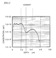
- FIG. 2 shows an ion implantation profile in the depth direction for the ring region 103f shown in FIG. 1 (b) .
- the "depth direction” refers to the direction that is defined by a normal to the principal surface of the semiconductor substrate 101 (i.e., the direction indicated by the line A-B shown in FIG. 1(b) ).
- an impurity concentration profile is different from an ion implantation profile.
- the impurity concentration often becomes lower than the concentration of impurity ions implanted because the percentage of activation of the impurity ions implanted is variable. If the percentage of activation is 100%, the ion implantation profile and the impurity concentration profile become substantially the same. For example, if the percentage of activation is supposed to be ⁇ %, the ion implant dose may be multiplied by 1/( ⁇ /100) so as to obtain the impurity concentration designed.
- Al may be selected as the implanted species, for example.
- SiC the diffusion coefficient of Al in silicon carbide is so small that the variation in concentration profile due to diffusion is almost negligible.
- B boron
- the ion implantation energy and implant dose are suitably selected so as to obtain an intended impurity concentration profile with the percentage of activation and the diffusion coefficient taken into account in advance.
- the percentage of activation is supposed to be 100% and the impurity concentration profile and the ion implantation profile are supposed to be substantially the same. That is to say, in the following description, the profile shown in FIG. 2 is supposed to represent the impurity concentration profile in the depth direction of the ring region 103f (including the high concentration ring region 103af and the low concentration ring region 103bf).
- the high concentration ring region 103af and the low concentration ring region 103bf may be formed by performing an ion implantation process in multiple steps with the implantation energy changed.
- the profile of impurity ions to be implanted in each ion implantation process step has a peak and a tail.
- the "peak” refers to a local maximum value of the concentration in the ion implantation range Rp
- the "tail” refers to a portion where the concentration decreases in the depth direction from that local maximum value.
- the ion implantation profile shown in FIG. 2 may be the sum of the profiles obtained through four ion implantation process steps, for example.
- Those ion implantation process steps may be carried out with the implantation energies and implant doses set to be: 30 keV and 3.0 ⁇ 10 13 ⁇ cm - 2 , 70 keV and 6.0 ⁇ 10 13 ⁇ cm - 2 , 150 keV and 1.5 ⁇ 10 14 ⁇ cm - 2 , and 350 keV and 4.0 ⁇ 10 13 ⁇ cm - 2 , respectively.
- the impurity concentrations of the high concentration and low concentration ring regions 103af and 103bf may be about 1 ⁇ 10 19 cm -3 and about 2 ⁇ 10 18 cm -3 , respectively, at maximum.
- the high concentration and low concentration ring regions 103af and 103bf may have average impurity concentrations of about 9.7 ⁇ 10 18 cm -3 and about 1.5 ⁇ 10 18 cm -3 , respectively.
- the thicknesses (depths) of the high concentration and low concentration ring regions 103af and 103bf may be approximately 300 nm each.
- the average impurity concentration of the high concentration ring region 103af is defined herein to be the average value of a region that has an impurity concentration of 2 ⁇ 10 18 cm -3 or more.
- the average impurity concentration of the low concentration ring region 103bf is defined herein to be the average value of a region that has an impurity concentration of 5 ⁇ 10 17 cm -3 to less than 2 ⁇ 10 18 cm -3 .
- the average impurity concentrations according to this embodiment are defined to be "2 ⁇ 10 18 cm -3 or more" and "5 ⁇ 10 17 cm -3 or more", respectively, in order to indicate their suitable value clearly, these values may also be changed depending on the type of the element to design.
- the average impurity concentration of the high concentration ring region 103af is suitably twice to one hundred times as high as that of the low concentration ring region 103bf.
- the reference impurity concentrations of "2 ⁇ 10 18 cm -3 or more" and “5 ⁇ 10 17 cm -3 or more” according to this embodiment are based on the impurity concentration Cs in the vicinity of the boundary between the high concentration ring region 103af and the low concentration ring region 103bf.
- the regions, of which the average impurity concentrations need to be calculated are determined so that their average impurity concentrations become Cs ⁇ 2 or more and Cs/2 or more, respectively, with Cs defined to be equal to 1 ⁇ 10 18 cm -3 .
- the concentration profile includes a first range which is substantially flat and a second range which is deeper, and has a lower concentration, than the first range.
- the high concentration ring region 103af covers the first range and the low concentration ring region 103bf covers the second range.
- the concentration profile does not have to be the illustrated one but its shape may vary according to the ion implantation process condition or the number of implantation process steps carried out.
- the thicknesses (as measured along a normal to the principal surface of the semiconductor substrate 101 ) of the respective ring regions 103af and 103bf do not have to be the exemplary values described above. However, it is recommended that the thickness of the high concentration ring region 103af be 15 nm or more and that the thickness of the low concentration ring region 103bf be 100 nm or more. In that case, the overconcentration of an electric field that would otherwise be produced around the bottom corners of the ring region 103 can be reduced more securely and a depletion layer which links adjacent ring regions 103af together can be formed with more certainty.
- the semiconductor element 100 may further include a diode region 115d between the unit cell region 100ul and the terminal region 100f.
- the diode region 115d is arranged in a ring so as to surround the unit cell region 100ul.
- the diode region 115d may be arranged discretely between the unit cell region 100ul and the terminal region 100f.
- the diode region 115d may also be arranged only locally around the unit cell region 100ul.
- a region of the second conductivity type (e.g., p-type region in this example) 103d is arranged in this embodiment in the diode region 115d of the first silicon carbide semiconductor layer 102.
- the region of the second conductivity type 103d and the drift region 102d form a pn junction diode.
- the respective regions 103ad and 103bd have the same concentration profiles as the high concentration ring region 103af and the low concentration ring region 103bf, respectively. That is to say, the high concentration region 103ad contacts with the surface of the first silicon carbide semiconductor layer 102.
- the low concentration region 103bd is located deeper, and has a lower impurity concentration, than the high concentration region 103ad and its bottom contacts with the drift region 102d. Also, at least a part of the side surface of the low concentration region 103bd and high concentration region 103ad which faces the ring region 103f suitably contacts with the drift region 102d.
- the region of the second conductivity type 103d is electrically connected to an electrode layer (which may be a source electrode layer, for example) which is arranged over the first silicon carbide semiconductor layer 102.
- the region of the second conductivity type 103d is different from the ring region 103f of the same conductivity type.
- the region of the second conductivity type 103d may be arranged outside of a unit cell that defines the periphery of the unit cell region 100ul (which will be referred to herein as a "peripheral cell") and may be separated from the peripheral cell by the drift region 102d.
- a part of the body region 103 of the peripheral cell (which may be located closer to the terminal region 100f) may be used as the region of the second conductivity type 103d.
- no impurity region (source region) 104 may be defined in that part of the body region 103 to be used as the region of the second conductivity type 103d but an impurity region 104 may be defined only in a part of the body region 103 functioning as a unit cell.
- an ohmic electrode (which will be referred to herein as a "second ohmic electrode") 110.
- the second ohmic electrode 110 functions as a drain electrode, for example, in the unit cell region 100ul. If a potential of zero volts is applied to the region of the second conductivity type 103ad and if a positive voltage is applied to the drain electrode 110, a reverse bias is applied to the pn junction formed between the low concentration region 103bd and the drift region 102d.
- each ring region 103f was supposed to be substantially perpendicular to the surface of the semiconductor substrate 101.
- each ring region 103f was supposed to have a width (i.e., the maximum width of the ring region 103f as measured on the upper surface) of 1 ⁇ m and a depth of 0.6 ⁇ m.
- the impurity concentration profile of the ring region 103f was supposed to be the same as the profile shown in FIG. 2 .
- the region of the second conductivity type 103d arranged in the diode region 115d was supposed to have the same concentration distribution and the same depth as the ring regions 103f.
- the breakdown voltage turned out to be 865 V.
- the breakdown voltage of the traditional semiconductor element 1000 (see FIG. 12 ) in the ring regions 1030f was calculated.
- the ring regions 1030f were supposed to have a constant concentration in the depth direction and have a depth of 0.6 ⁇ m.
- the number, interval and width of the ring regions 1030f were supposed to be the same as those of the ring regions 1030f of the specific example of the present invention.
- the p-type region 1030d was supposed to have the same concentration distribution and the same depth as the ring regions 1030f.
- the breakdown voltage was 852 V.
- the breakdown voltages were also calculated in the same way with the impurity concentration of the ring regions 1030f increased. For example, when the impurity concentrations were 5 ⁇ 10 18 cm -3 , 1 ⁇ 10 19 cm -3 and 2 ⁇ 10 19 cm -3 , the breakdown voltages were 804 V, 794 V and 772 V, respectively. These results of calculation reveal that in the comparative example, if the drift region 1020d had a constant impurity concentration and a constant thickness, the higher the concentration in the ring regions 1030f, the smaller the breakdown voltages in the diode region 1150d and terminal region 1000f.
- the impurity concentration in the ring regions 1030f was set to be low (e.g., as low as the impurity concentration in the low concentration ring region 103bf of the specific example of the present invention) or high (e.g., as high as the impurity concentration in the high concentration ring region 103af of the specific example of the present invention)
- the breakdown voltages achieved were less high in the comparative example than in the specific example of the present invention.
- the concentration in the ring regions 1030f of the comparative example is set to be 2 ⁇ 10 18 cm -3 , for example, then the electric field will be overconcentrated at the corners of the ring regions 1030f (as indicated by the arrows 2000 shown in FIG. 12 ), thus determining the breakdown voltage.
- the impurity concentration is higher according to the specific example of the present invention in the upper part of the ring regions 103f than at the corners, then electric field applied to the respective corners of the ring regions 103f is weakened parallel to the surface of the substrate.
- the overconcentration of the electric field around the corner portions can be reduced and the decrease in breakdown voltage due to the presence of a pn junction can be minimized in the diode region 115d and the terminal region 100f.
- the breakdown voltage will be 772 V. That is to say, it can be seen that the decrease in breakdown voltage cannot be minimized simply by increasing the concentration in the ring regions 1030f. Rather an increase in the concentration in the ring regions 1030f would further decrease the breakdown voltage. This is probably because an even higher electric field should be applied to the corners of the ring regions 1030f.
- the breakdown voltage achieved can be higher than in a situation where the concentration is set to be low in the entire ring region and in a situation where the concentration is set to be high in the entire ring region.
- Such an effect of minimizing the decrease in breakdown voltage can be achieved as long as the high concentration ring region 103af has a higher impurity concentration than the low concentration ring region 103bf.
- the concentration in the high concentration ring region 103af is suitably twice or more as high as in the low concentration ring region 103bf. Then, the decrease in breakdown voltage can be minimized even more effectively.
- a side surface of the high concentration ring regions 103af of this embodiment contacts directly with the drift region 102d as shown in FIG. 1(b) . And suitably the entire side surface of the high concentration ring region 103af contacts with the drift region 102d.
- the interval between adjacent ring regions 103f can be further reduced. The higher the concentration at the side surface of the ring regions 103f is, the thicker the depletion layer that expands from the side surface parallel to the substrate becomes. As a result, even if the interval between adjacent ring regions 103f is decreased, the depletion layers can still be linked together and the intended breakdown voltage can be achieved more securely.
- the terminal region 100f that complements the breakdown voltage of the element function does not contribute to electrical conduction when the MISFET is in ON state. That is why as long as the intended breakdown voltage can be achieved, the area of the terminal region 100f (as viewed along a normal to the principal surface of the semiconductor substrate 101 ) is suitably as small as possible. By reducing the area of the terminal region 100f, the chip area of the semiconductor element 100 can be reduced and the cost of the semiconductor element 100 can be cut down significantly.
- FIG. 3 illustrates an example of a semiconductor element 100 according to this embodiment.
- the semiconductor element 100 shown in FIG. 3 is a vertical MISFET.
- FIG. 3 (a) is a top view of the semiconductor element 100 just like FIG. 1(a) , and its description will be omitted herein.
- a plurality of unit cells 100n are arranged two-dimensionally.
- FIG. 3(b) is a schematic cross-sectional view of each unit cell 100u of the semiconductor element 100 according to this embodiment.
- FIG. 3(c) is a schematic cross-sectional view illustrating the terminal region 100f and diode region 115d of the semiconductor element 100.
- the semiconductor element 100 includes a semiconductor substrate 101 of a first conductivity type and a first silicon carbide semiconductor layer (drift layer) 102 which has been formed on the principal surface of the substrate 101.
- the first conductivity type is n type and the second conductivity type is p type.
- the first and second conductivity types may also be p and n types, respectively.
- the semiconductor substrate 101 has n + conductivity and is made of silicon carbide.
- the first silicon carbide semiconductor layer 102 is of n - type and has the drift region 102d.
- the superscript "+" or "-" added to the conductivity type "n" or "p” represents the relative concentration of the impurity introduced. That is to say, “n + “ means that the concentration of an n-type impurity added is higher than "n”, while “n - " means that the concentration of an n-type impurity added is lower than "n”.
- a body region 103 of the second conductivity type is arranged adjacent to the drift region 102d.
- the rest of the first silicon carbide semiconductor layer 102 other than the body region 103 is the drift region 102d.
- the body region 103 includes a first body region 103a of the second conductivity type and a second body region 103b of the second conductivity type.
- the first body region 103a contacts with the surface of the first silicon carbide semiconductor layer 102 and the bottom of the second body region 103b contacts with the first silicon carbide semiconductor layer 102 (i.e., the drift region 102d in this example).
- the first and second body regions 103a and 103b have thicknesses of at least 15 nm and at least 100 nm, respectively.
- the first body region 103a is of p + type and the second body region 103b is of p-type.
- the average impurity concentration of the first body region 103a is twice or more as high as that of the second body region 103b.
- the body region 103 is formed by introducing an impurity of the second conductivity type into the first silicon carbide semiconductor layer 102 of the first conductivity type. That is why the body region 103 includes both an impurity of the first conductivity type and the impurity of the second conductivity type and is defined to be a region in which the concentration of the impurity of the second conductivity type is higher than that of the impurity of the first conductivity type. At the bottom 103u of the body region 103, the concentration of the impurity of the first conductivity type in a part of the first silicon carbide semiconductor layer 102 that contacts with the body region 103 is as high as that of the impurity of the second conductivity type in the second body region 103b. Also, when viewed perpendicularly to the principal surface of the semiconductor substrate 101, the contours of the first and second body regions 103a and 103b match with each other.
- An impurity region 104 of the first conductivity type is provided in the body region 103. More specifically, the impurity region 104 is arranged in the first body region 103a so as to contact with the surface 102 of the first silicon carbide semiconductor layer 102.
- the impurity region 104 is of n + type.
- a contact region 105 of the second conductivity type is suitably provided in the first body region 103a and may be of p + type.
- the contact region 105 contacts with at least the first body region 103a and suitably contacts with the second body region 103b, too.
- a first ohmic electrode 109 has been formed over the impurity region 104.
- the first ohmic electrode 109 covers the respective surfaces of, and is electrically in contact with, both of the impurity region 104 and the contact region 105. If the first body region 103a has a sufficiently high impurity concentration, then the contact region 105 may be omitted. In that case, a contact trench may be cut so as to expose the first body region 103a and be filled with the first ohmic electrode 109, thereby making the first body region 103a and the first ohmic electrode 109 contact directly with each other.
- a portion 102j of the drift region 102d which is adjacent to the body region 103 will be referred to herein as a JFET (junction field-effect transistor) region for the sake of simplicity of description.
- This region forms part of the drift region 102d of the first silicon carbide semiconductor layer 102.
- the impurity concentration of the JFET region 102j may be the same as that of the rest of the drift region 102d other than the JFET region 102j. However, in order to reduce the resistance in the JFET region 102j, the JFET region 102j may have a higher impurity concentration than the rest of the drift region 102d.
- Such a JFET region 102j may be formed by introducing an impurity of the first conductivity type (which is n-type in this example) into a predetermined portion of the drift region 102d by ion implantation, for example. If the rest of the drift region 102d other than the JFET region 102j has an impurity concentration of about 5 ⁇ 10 15 cm -3 , the JFET region 102j may have a concentration of 1 ⁇ 10 17 cm -3 , for example.
- first silicon carbide semiconductor layer 102 On the first silicon carbide semiconductor layer 102, arranged is a second silicon carbide semiconductor layer 106 of the first conductivity type, which contacts at least partially with the body region 103 and the impurity region 104. It will be more beneficial if the second silicon carbide semiconductor layer 106 is electrically connected to the impurity region 104 and the drift region 102d (i.e., the JFET region 102j) and is located over the first body region 103a.
- the second silicon carbide semiconductor layer 106 is electrically connected to the impurity region 104 and the drift region 102d (i.e., the JFET region 102j) and is located over the first body region 103a.
- the second silicon carbide semiconductor layer 106 has been grown epitaxially.
- the second silicon carbide semiconductor layer 106 has a channel region 106c in its portion that contacts with the first body region 103a.
- the length of the channel region 106c (which will be referred to herein as a "channel length L") is as indicated by each of the two double-headed arrows shown in FIG. 3(b) . That is to say, the "channel length" of the MISFET is defined by a horizontal size measured on the upper surface of the first body region 103a (i.e., the surface that contacts with the second silicon carbide semiconductor layer 106) on the paper.
- a gate insulating film 107 has been formed on the second silicon carbide semiconductor layer 106.
- a gate electrode 108 is arranged on the gate insulating film 107.
- the gate electrode 108 is located over the channel region 106c to say the least.
- the second silicon carbide semiconductor layer 106 may be omitted and the gate insulating film 107 may be arranged so as to contact with the first silicon carbide semiconductor layer 102.
- a channel i.e., an inversion channel layer
- An interlevel dielectric film 111 has been deposited over the gate electrode 108, and an upper interconnect electrode 112 is stacked on the interlevel dielectric film 111.
- the upper interconnect electrode 112 is connected to the first ohmic electrode 109 through a contact hole 111c that has been cut through the interlevel dielectric film 111.
- On the back surface of the semiconductor substrate 101 arranged is a second ohmic electrode 110. And a back surface interconnect electrode 113 may be further stacked on the second ohmic electrode 110.
- each unit cell 100u of the semiconductor element 100 may have a square shape, for example.
- the unit cell 100u may also have a rectangular shape, a quadrilateral shape or any other polygonal shape as well.
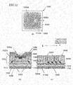
- FIG. 4(a) illustrates a cross-sectional structure in a situation where unit cells 100u are arranged in parallel.
- the unit cells 100u may be arranged two-dimensionally in x and y directions, and rows of unit cells may shift alternately by a half pitch in the y direction.
- the unit cells 100u may also be arranged regularly as shown in FIG. 4(b2) .
- the unit cells 100u may also be arranged in parallel as shown in FIG. 4(c) .
- the unit cell region 100ul of the semiconductor element is formed by a number of unit cells 100u that are arranged in this manner.
- the terminal region 100f and the diode region 115d are arranged around the unit cell region 100ul. These regions have the same basic configuration as their counterparts shown in FIG. 1(b) . But their configurations are illustrated more specifically in FIG. 3(c) .
- any component also shown in FIG. 1(b) is identified by the same reference numeral and a detailed description thereof will be omitted herein to avoid redundancies.
- the diode region 115d arranged is the region of the second conductivity type 103d including the high concentration region 103ad of the second conductivity type and the low concentration region 103bd of the second conductivity type.
- the contact region 105 of the second conductivity type is further arranged in the region of the second conductivity type 103d.
- the contact region 105 is electrically connected to at least the high concentration region 103ad.
- the high and low concentration regions 103ad and 103bd of the second conductivity type have substantially identical impurity concentration profile in the depth direction as the first and second body regions 103a and 103b, respectively.
- the first ohmic electrode 109 contacts with the high concentration region 103ad and the contact region 105 in the region of the second conductivity type 103d. As described above, if the impurity concentration of the high concentration region 103ad is sufficiently high, the contact region 105 is not necessarily provided. In that case, by cutting a contact trench through the high concentration region 103ad and filling the trench with the first ohmic electrode 109, the first ohmic electrode 109 may be brought into direct contact with the high concentration region 103ad. Also, the second silicon carbide semiconductor layer 106, the gate insulating film 107, and the gate electrode 108 which have been formed in the unit cell region 100ul may be extended to a portion of the diode region 115d.
- the source region is not arranged in the region of the second conductivity type 103d, no channel is formed there.
- only a portion of the body region 103 of the peripheral cell which is located closer to the terminal region 100f may function as the region of the second conductivity type 103d.
- the source region 104 is arranged only in a portion of body region 103 of the peripheral cell which is located closer to the unit cell region 100ul.
- the region of the second conductivity type 103d contacts with the first ohmic electrode 109 in the hole that has been cut through the interlevel dielectric film 111.
- the first ohmic electrode 109 is connected to the upper interconnect electrode 112.
- the region of the second conductivity type 103d is electrically connected in parallel to the unit cell region 100ul via the upper interconnect electrode 112.
- the diode region 115d is suitably formed by using the structure of each unit cell 100u in the unit cell region 100ul.
- the diode region 115d may have the same structure as the unit cell 100u except that the diode region 115d does not have the second silicon carbide semiconductor layer 106 or the impurity region 104. That is to say, a portion of the unit cell 100u corresponding to the body region 103 becomes the region of the second conductivity type 103d.
- the p-type layer arranged in the unit cell region 100ul may be extended to the diode region 115d to define the region of the second conductivity type 103d.
- the thicknesses of the respective regions 103ad and 103bd of the region of the second conductivity type 103d are not particularly limited. But the high concentration region 103ad suitably has a thickness of 15 nm or more and the low concentration region 103bd suitably has a thickness of 100 nm or more. Then, the overconcentration of an electric field to be produced around the bottom corners of the region of the second conductivity type 103d can be reduced more securely.
- the ring region 103f (more specifically, the high concentration ring region 103af) is covered with the interlevel dielectric film 111.
- a stopper region 104f of the first conductivity type which prevents a depletion layer produced by a pn junction from reaching the chip edge
- the upper interconnect 112f, and a contact electrode 109f which electrically connects the stopper region 104f and the upper interconnect 112f together
- the upper interconnect 112f and the contact electrode 109f are arranged to fill the holes of the interlevel dielectric film 111.
- the upper interconnect electrode 112 and the upper interconnect 112f do not directly contact with each other.
- the upper interconnect electrode 112 and the upper interconnect 112f may be made of the same conductor film.
- the stopper region 104f may be an n + -type region having identical impurity concentration as the source region 104.
- a passivation film 114 is provided so as to cover the upper interconnect 112f entirely and the upper interconnect electrode 112 partially.
- the passivation film 114 may cover the unit cell 100u on the unit cell region 100ul at least partially.
- the back surface interconnect electrode 113 may be arranged on the second ohmic electrode 110.
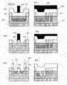
- portions (a1) through (a3) are cross-sectional views illustrating respective process steps to be performed on the unit cell region 100ul
- portions (b1) through (b3) are cross-sectional views illustrating respective process steps that are to be performed on the terminal region 100f and that correspond to the processing steps illustrated in portions (a1) through (a3), respectively.
- the semiconductor substrate 101 may be a low-resistance n-type 4H-SiC off-axis cut substrate (with a resistivity of 0.02 ⁇ cm), for example.
- a first silicon carbide semiconductor layer 102 with high resistance is grown epitaxially on the semiconductor substrate 101.
- a buffer layer made of SiC with a high impurity concentration may be deposited on the semiconductor substrate 101. Illustration of the buffer layer is omitted herein for the sake of simplicity.
- the buffer layer may have an impurity concentration of 1 ⁇ 10 18 cm -3 and a thickness of 1 ⁇ m, for example.
- the first silicon carbide semiconductor layer 102 may be made of n-type 4H-SiC and may have an impurity concentration of 1 ⁇ 10 16 cm -3 and a thickness of 10 ⁇ m, for example.
- the first silicon carbide semiconductor layer 102 is partially covered with a mask 201 of SiO 2 , for example.
- ions of Al are implanted into portions of the first silicon carbide semiconductor layer 102 to be a body region, a diode region and ring regions.
- a first body implanted region 103a' is formed as a high concentration region in a shallow region of the first silicon carbide semiconductor layer 102 and a second body implanted region 103b' is formed so as to be located deeper and contain the ions at lower concentration than the first body implanted region 103a'.
- a high concentration implanted ring region 103af' and a low concentration implanted ring region 103bf' that will form the ring region 103f later and a high concentration implanted region 103ad' and a low concentration implanted region 103bd' that will form the region of the second conductivity type 103d later are defined at the same time. Consequently, a ring region that can minimize a decrease in breakdown voltage in the terminal region 100f can be formed as described above. In addition, by carrying out the ion implantation to define those ring regions and the ion implantation to define those body regions at the same time, the process can be simplified, too.
- the first and second body implanted regions 103a' and 103b' When the ions implanted are activated, the first and second body implanted regions 103a' and 103b' will be first and second body regions 103a and 103b, respectively. Meanwhile, the rest of the first silicon carbide semiconductor layer 102', other than the first and second body regions 103a and 103b, will define a drift region 102. In this process step, the implantation profile of the body region 103 may be the same as the one shown in FIG. 2 , for example.
- the regions 103a', 103ad' and 103af' having high impurity concentration and regions 103b', 103bd' and 103bf' having low impurity concentration formed by using the same mask 201 Consequently, the process can be simplified in this respect, too.
- the regions having high impurity concentration and the regions having low impurity concentration come to have substantially matching contours because those two groups of regions have been formed using the same mask 201.
- the interval between the body regions 103 of two adjacent unit cells can be reduced to a sufficiently small value.
- the interval between the body regions 103 can be set to be the intended value (which may be 1 ⁇ m, for example). If the terminal structure includes a plurality of implanted layers in multiple different regions as in the JTE structure, it is very difficult to form the unit cell and the terminal region at the same time as accurately as is done in this embodiment. If a region having high impurity concentration and a region having low impurity concentration were formed by two different processes, the mask should be rearranged and should have its shapes changed. As a result, the interval between the body regions (which will eventually define the width of the JFET region) could not be set to be the intended value.
- the intended value which may be 1 ⁇ m, for example.
- the implantation might be off target parallel to the surface of the substrate.
- the first and second body implanted regions 103a' and 103b' might have their contours shifted from each other and the JFET region might become narrower, which would lead to an increase in the ON-state resistance of the MISFET. That is why according to this embodiment, it is recommended that the first and second body implanted regions 103a' and 103b' be formed using the same mask 201.
- the interval between adjacent ring regions 103f can be decreased.
- the area allocated to the terminal region 100f can be reduced and eventually the chip area itself can be reduced.
- the high concentration implanted region 103ad' and the low concentration implanted region 103bd' to be the region of the second conductivity type 103d eventually are formed using the same mask 201, the area allocated to the diode region 115d can be reduced.
- the mask 201 is entirely covered with another mask 202.
- the photoresist is patterned so as to cover the terminal region, the diode region and a region to be the contact region, thereby making a resist mask 203.
- the masks 201 and 202 are suitably made of materials that can have the intended selectivity in the dry etching process.
- the mask 201 may be made of SiO 2 and the mask 202 may be made of polysilicon.
- the mask 202 is dry-etched using the resist mask 203 as an etching mask.
- the resist mask 203 as an etching mask.
- the mask 202 is covered with the resist mask 203 and is not etched (see FIG. 6(b2) ).
- the resist mask 203 is removed and then portions of the first silicon carbide semiconductor layer 102 which are not covered with the masks 201 and 202 or the sidewall 202' are doped with N ions, for example, thereby forming a source implanted region 104'.
- this region 104' is formed by ion implantation, the ion implantation conditions including the implant energy and the implant dose are selected so that an n-type region with an impurity concentration of about 5 ⁇ 10 19 cm -3 is formed to have a thickness of approximately 200 to 300 nm.
- the source implanted region 104' is defined in the first body implanted region 103a'.
- the width of a portion corresponding to the channel of a MISFET i.e., the length L' that will eventually define the gate length L as shown in FIG. 6(a3) , can be controlled precisely.
- the length L or L' is defined by the width of the sidewall 202' and may be approximately 0.5 ⁇ m, for example.
- the gate length L to be the intended value in a MISFET with a channel layer, it is recommended that the source implanted region 104' and body implanted region 103' be formed accurately in the first silicon carbide semiconductor layer 102 by the self-alignment process shown in FIG. 6(a2) . If the source implanted region 104' and the body implanted region 103' were formed without adopting the self-alignment process described above, then misalignment could occur even within the same unit cell and the predetermined gate length L could not be obtained. What is more, as the case may be, the gate length L could become so short due to the misalignment that the channel of the transistor could cause short circuit.
- the gate length L may be set to be sufficiently long with the possible mask misalignment taken into account. However, if the gate length L were sufficiently long, then the channel resistance of the transistor would rise and the ON-state resistance might increase as a result. For that reason, the self-alignment process is suitably adopted to make the masks 201 and 202 to define the source region.
- the masks 201, 202 and 202' are all removed and then another mask 204 is made on the first silicon carbide semiconductor layer 102.
- the mask 204 has an opening over a portion of the terminal region in which a stopper region will be defined.
- N ions for example, are implanted into the first silicon carbide semiconductor layer 102, thereby forming a stopper implanted region 104f'.
- This ion implantation process step may be carried out under the same condition as the one for forming the source implanted region 104', for example.
- the mask 204 is removed and another mask 205 is made on the first silicon carbide semiconductor layer 102 as shown in FIGS. 7(a2) and 7(b2) .
- the mask 205 has an opening over a contact region to be.
- Al ions for example, are implanted into the first silicon carbide semiconductor layer 102, thereby forming a contact implanted region 105'.
- the contact implanted region 105' is formed inside a region to be the body region and a region to be the diode region.
- the implantation conditions of this process step may be selected so that the impurity concentration becomes approximately 1 ⁇ 10 20 cm -3 and the depth becomes approximately 400 nm.
- the contact implanted region 105' is formed in the first body implanted region 103a' but suitably reaches the inside of the second body implanted region 103b' as shown in FIG. 7(a2) . That is to say, the contact implanted region 105' suitably contacts with the first body implanted region 103a' at the upper portion of the side surface and with the second body implanted region 103b' at the lower portion and bottom of the side surface. After that, the mask 205 is removed.
- FIGS. 7(a3) and 7(b3) another mask 206, having an opening over a JFET region to be, is made, if necessary, on the first silicon carbide semiconductor layer 102 and N ions are implanted into the drift region 102d, thereby forming a JFET implanted region 102j', which may have an impurity concentration of approximately 1 ⁇ 10 17 cm -3 and an implantation depth of approximately 0.6 to 1 ⁇ m.
- the mask 206 is removed. Subsequently, an activation annealing process is carried out at an elevated temperature of approximately 1600 to 1900 degrees Celsius. As a result, as shown in FIGS. 8(a1) and 8(b1) , the implanted regions 103a', 103b', 103ad' , 103bd', 103af', 103bf', 104' , 105' and 104f' can be turned into a first body region 103a, a second body region 103b, a high concentration region 103ad, a low concentration region 103bd, a high concentration ring region 103af, a low concentration ring region 103bf, an impurity region 104, a contact region 105 and a stopper region 104f, respectively.
- the activation annealing process is suitably carried out with a carbon film (not shown) deposited on the surface of the first silicon carbide semiconductor layer 102 (i.e., the surface in which the implanted regions have been formed). In this manner, it is possible to prevent the surface of the first silicon carbide semiconductor layer 102 from being roughened through the activation annealing process.
- the carbon film deposited on the surface, if any, is removed.
- the carbon film can be removed by being exposed to oxygen plasma, for example.
- the surface of the first silicon carbide semiconductor layer 102 can be cleaned by slightly oxidizing the surface of the first silicon carbide semiconductor layer 102 and removing the thermal oxide film (with a thickness of about 15 nm) thus formed.
- a layer 106' to be the second silicon carbide semiconductor layer (channel layer) is grown epitaxially over the entire surface of the first silicon carbide semiconductor layer 102, including the first body region 103a, the impurity region 104 and the contact region 105.
- the thickness d' of the layer 106' to be the second silicon carbide semiconductor layer is supposed to be d+d0 with respect to the thickness d of the second silicon carbide semiconductor layer, where d0 indicates the decrease in the thickness of the layer to be the second silicon carbide semiconductor layer owing to a thermal oxidation process to be described later. For example, if the decrease in thickness d0 is 50 nm, the thickness d' of the layer 106' to be the second silicon carbide semiconductor layer is 80 nm.
- a predetermined portion of the layer 106' to be the second silicon carbide semiconductor layer is dry-etched away, thereby obtaining the second silicon carbide semiconductor layer 106.
- portions of the second silicon carbide semiconductor layer 106' which are located in the terminal region and diode region are removed.
- a gate insulating film 107 is formed by thermal oxidation, for example, on the surface of the second silicon carbide semiconductor layer 106.
- a gate electrode 108 is formed on a predetermined portion of the gate insulating film 107.
- the gate insulating film 107 is formed by thermal oxidation, a part of the second silicon carbide semiconductor layer 106 will also form part of the gate insulating film 107. That is why the thickness of the layer 106' to be the second silicon carbide semiconductor layer (see FIG. 8(b1) ) is adjusted with the decrease in thickness due to the thermal oxidation taken into account so that the second silicon carbide semiconductor layer 106 will have the thickness d when the gate insulating film 107 is formed.
- the thickness of the layer 206' to be the second silicon carbide semiconductor layer is set to be approximately 50 nm larger than the thickness d
- the thickness of the second silicon carbide semiconductor layer 106 that will be obtained after having gone through the process step of cleaning the second silicon carbide semiconductor layer 106 to be performed before the gate insulating film 107 is formed and the process step of forming the gate insulating film 107 will be approximately equal to the predetermined thickness d.
- the gate electrode 108 may be formed by depositing a polysilicon film doped with phosphorus at a dose of approximately 7 ⁇ 10 20 cm -3 on the gate insulating film 107 and dry etching the polysilicon film through a mask (not shown).
- the polysilicon film may have a thickness of approximately 500 nm.
- the gate electrode 108 is arranged so as to cover a portion of the second silicon carbide semiconductor layer 106 that will be a channel.
- a portion to be the channel of a MISFET can be formed with good controllability.
- the self alignment process cannot be applied to the body region, and therefore, there is a concern about a short circuit of the channel and an increase in ON-state resistance. For that reason, it is recommended that the second silicon carbide semiconductor layer 106 be formed over the source region 104 and body region 103 that have been formed by the self alignment process.
- an interlevel dielectric film 111 is deposited by CVD process, for example, so as to cover the respective surfaces of the gate electrode 108 and the first silicon carbide semiconductor layer 102.
- the interlevel dielectric film 111 may be made of SiO 2 , for example, and has a thickness of 1 ⁇ m, for example.
- the interlevel dielectric film 111, the gate insulating film 107 and the second silicon carbide semiconductor layer 106 are selectively dry-etched through a mask (not shown), thereby cutting a contact hole 111A that exposes a part of the surface of the impurity region 104 and the surface of the contact region 105, a contact hole 111B that exposes a part of the surface of the high concentration region 103ad and the surface of the contact region 105, and a contact hole 111C that exposes the surface of the stopper region 104f.
- a first ohmic electrode 109 is formed inside the contact holes 111A and 111B and a contact electrode 109f is formed inside the contact hole 111C. Meanwhile, a second ohmic electrode 110 is formed on the other side (i.e., the back surface) of the semiconductor substrate 101 opposite from its principal surface.
- a metal film such as a nickel film is deposited to a thickness of about 100 nm, for example, to cover the interlevel dielectric film 111 and to fill the contact holes 111A, 111B and 111C.
- a heat treatment is carried out at 950 degrees Celsius for five minutes, for example, within an inert atmosphere, thereby making the metal film (e.g., the nickel film in this embodiment) react with the surface of silicon carbide.
- the nickel film on the interlevel dielectric film 111 and the residue of the nickel that has not reacted with the silicon carbide in the contact holes 111A, 111B and 111C are removed.
- a first ohmic electrode 109 of a metal silicide (e.g., nickel silicide in this embodiment) is formed inside the contact holes 111A and 111B.
- a contact electrode 109f of nickel silicide is also formed inside the contact hole 111C.
- the second ohmic electrode 110 may also be formed by depositing a nickel film, for example, over the entire back surface of the semiconductor substrate 101 and making the nickel film react with the silicon carbide surface of the semiconductor substrate 101 through a heat treatment.
- a metal film may be deposited on the back surface of the semiconductor substrate 101 and the heat treatments for forming the first and second ohmic electrodes may be carried out at the same time.
- a conductive film (such as an aluminum film) is deposited to a thickness of approximately 4 ⁇ m over the interlevel dielectric film 111 and inside the contact holes 111A, 111B and 111C and then selectively etched into an intended pattern.
- an upper interconnect electrode 112 is formed over the interlevel dielectric film 111 and inside the contact holes 111A and 111B and an upper interconnect 112f is formed over the interlevel dielectric film 111 and inside the contact hole 111C as shown in FIGS. 9(a3) and 9(b3) .
- a passivation film 114 may be formed to cover an exposed portion of the interlevel dielectric film 111, the upper interconnect electrode 112 and the upper interconnect 112f.
- the passivation film 114 is arranged over the terminal region 100f and the diode region 115d.
- the passivation film 114 may be a SiN film and may have a thickness of approximately 1.5 ⁇ m, for example.
- a gate line (or gate pad) which is electrically connected to the gate electrode 108 is formed in another region at the chip edge.
- a back surface interconnect electrode 113 to be die-bonded may also be formed on the back surface of the second ohmic electrode 110.
- the back surface interconnect electrode 113 may be a multilayer film consisting of Ti, Ni and Ag films that have been stacked in this order on the second ohmic electrode 110. In that case, the Ti film contacts with the second ohmic electrode 110. In this manner, the semiconductor element 100 shown in FIG. 3 is completed.
- the semiconductor element 100 of this embodiment includes the ring regions 103f, each of which is comprised of the high concentration ring region 103af and the low concentration ring region 103bf, in the terminal region 100f. That is why compared to the traditional semiconductor element 1000 (see FIG. 12 ) including the ring regions 1030f with a substantially uniform concentration profile, the decrease in breakdown voltage can be much less significant according to this embodiment. In addition, according to the method that has been described with reference to FIGS.
- the process can be simplified.
- the high and low concentration ring regions 103af and 103bf are formed simultaneously with the first and second body regions 103a and 103b and/or the high and low concentration regions 103ad and 103bd, the effect of simplifying the process can still be achieved.
- the regions having high impurity concentration and the regions having low impurity concentration are formed continuously using the same mask, and therefore, can be defined within the same area as viewed along a normal to the principal surface of the semiconductor substrate 101. That is why as there is no need to design the ring regions 103f at increased intervals by taking into account the possible misalignment between the patterns to be involved when the high and low concentration ring regions 103af and 103bf are formed by different processes, the area of the terminal region 100f can be reduced.
- the JFET region i.e., the interval between adjacent body regions
- the increase in the ON-state resistance of a MISFET due to the decrease in the area of the JFET region can also be minimized.
- the present inventors discovered and confirmed via experiments that if the first and second body regions 103a and 103b are formed while the high and low concentration ring regions 103af and 103bf are formed in the terminal region 100f as in the semiconductor element 100, the decrease in breakdown voltage in the unit cell region 100ul can also be checked.
- the body region 1030 is formed so as to have a substantially constant impurity concentration in the depth direction, and therefore, the electric field could be overconcentrated at the bottom corners 3000 of the body region 1030 as well as in the ring region 1030f, and the intended breakdown voltage could not be obtained.
- the body region 1030 is supposed to have a substantially constant impurity concentration in the depth direction and have a depth of 0.6 ⁇ m
- the drift region 1020d is supposed to have a concentration of 1 ⁇ 10 16 cm -3 .
- the breakdown voltage in the unit cell region becomes higher by 262 V than when the body region 1030 has an average impurity concentration of 2 ⁇ 10 19 cm -3 . This result revealed that the higher the concentration in the body region 1030, the more significantly the electric field got overconcentrated and the more steeply the breakdown voltage decreased.
- the present inventors confirmed that when the concentration profile in the depth direction of the ring regions 103f shown in FIG. 2 was applied to the body region 103, the decrease in breakdown voltage could be approximately 16 V smaller in the semiconductor element 100 of this embodiment than in a situation where the average impurity concentration in the body region 1030 was set to be 2 ⁇ 10 18 cm -3 in the traditional semiconductor element 1000.
- the present inventors further carried out experiments to examine how the decrease in the breakdown voltage of the element could be checked by a pn junction diode formed by the region of the second conductivity type 103d, the ring regions 103f and the drift region 102d.
- the results are as follows.
- the breakdown voltage of the terminal structure including the region of the second conductivity type 103d and the ring regions 103f was obtained as an example of the present invention.
- the breakdown voltage of a terminal structure including the p-type region 1030d and ring regions 1030f with a substantially uniform concentration profile in the depth direction as shown in FIG. 12(c) was obtained.
- the p-type region 1030d and the ring regions 1030f were supposed to have an impurity concentration of approximately 2 ⁇ 10 18 cm -3 .
- the region of the second conductivity type 103d of the example of the present invention and the p-type region 1030d of the comparative example were supposed to have the same appearance in terms of their depth and width, for example.
- the respective ring regions 103f and 1030f of the example of the present invention and the comparative example were supposed to have the same depth and same width and be provided in the same number.
- FIG. 10 is a graph showing the cumulative frequency distributions of elements breakdown voltages when the terminal structure of the example of the present invention and that of the comparative example (i.e., the pn junction diode) were adopted, respectively.
- the impurity concentration in the diode and ring regions was increased in an upper (i.e., shallower) portion (as in the example of the present invention)
- an element with a higher breakdown voltage was realized than in a situation where the entire diode and ring regions had identical impurity concentration (as in the comparative example).
- the element's breakdown voltage achieved by the terminal structure of the comparative example was 671 V, while an element's breakdown voltage of 728 V was achieved by the terminal structure of the example of the present invention.
- each unit cell 100u of this embodiment includes a body region 103 comprised of first and second body regions 103a and 103b with different concentrations, the breakdown voltage of the element can be decreased. On top of that, by controlling the impurity concentrations of the upper and lower layers of the body region 103 independently of each other, the following effect can also be obtained.
- the semiconductor element 100 can also function as a diode which makes current flow from the first ohmic electrode (source electrode) 109 toward the second ohmic electrode (drain electrode) 110 through the second silicon carbide semiconductor layer (channel layer) 106 while keeping the threshold voltage Vth of the transistor positive (i.e., while maintaining the transistor in normally off state).
- the first body region 103a has an average impurity concentration of 2 ⁇ 10 19 cm -3
- the second silicon carbide semiconductor layer 106 has an impurity concentration of 2.3 ⁇ 10 18 cm -3 and a thickness of 30 nm
- the gate insulating film 107 has a thickness of 70 nm.
- the semiconductor element 100 can set the turn-on voltage of the diode (i..e., the voltage between the first and second ohmic electrodes (i.e., source and drain electrodes) 109 and 110 that needs to be applied to flow a current of 1 mA in absolute value through the diode) to be approximately 0.5 V while keeping the threshold voltage of the transistor positive, and has a totally different current-voltage characteristic from a pn diode comprised of the body region 103 and the drift region 102d (with a turn-on voltage of approximately 2.5 V). If the semiconductor element 100 is made to operate as a diode, that diode will be referred to herein as a "channel diode" for convenience sake.
- the semiconductor element 100 is made to operate as a diode, that diode will be referred to herein as a "channel diode" for convenience sake.
- the potential of the second ohmic electrode D with respect to the potential of the first ohmic electrode S is identified herein by Vds
- the potential of the gate electrode G with respect to the potential of the first ohmic electrode S is identified herein by Vgs
- the direction of current flowing from the second ohmic electrode D toward the first ohmic electrode S is defined herein to be "forward direction”
- the direction of current flowing from the first ohmic electrode S toward the second ohmic electrode D is defined herein to be "reverse direction”.
- the semiconductor element 100 of the present invention can control, independently of each other, the second body region 103b that affects the breakdown voltage of the element and the first body region 103a that affects the threshold voltage Vth of the transistor and the turn-on voltage Vf0 of the channel diode.
- the channel diode can be used as a freewheeling diode which is connected anti-parallel to a transistor in an inverter circuit, and a highly reliable semiconductor element with a high breakdown voltage can be provided.
- of the channel diode In order to decrease the turn-on voltage
- the turn-on voltage of the channel diode is set to be 0.6 V or less, a fast recovery diode of Si can be replaced. That is to say, the semiconductor element 100 can also function as a freewheeling diode by itself, and therefore, there is no need to use any of these freewheeling diodes anymore.
- a channel diode with a low turn-on voltage (of 1 V or less) works, a large amount of current can be obtained with almost no current allowed to flow through a body diode that has a pn junction formed by the body region 103 and the drift region 102d.
- the traditional semiconductor element if a large amount of current is allowed to flow through a pn junction continuously, imperfections in SiC will grow to cause an increase in the ON-state resistance of the semiconductor element and in the resistance of the body diode, which is a problem.
- the semiconductor element 100 of this embodiment can function as a diode almost without allowing current to flow through the body diode. As a result, high reliability can be maintained without increasing the crystal imperfections.
- the threshold voltage Vth of the forward current is suitably 2 V or more.
- a semiconductor element to be ordinarily used in an inverter circuit that is a power circuit is suitably normally OFF (i.e., Vth>0 V). This is because even if the gate controller went out or order and the gate voltage went 0 V for some reason, the drain current could still be shut off safely in that case.
- the threshold voltage were too high, the gate voltage to be applied to turn the transistor ON would increase accordingly, and a lot of constraints would be imposed on the power supply to generate the gate voltage. For that reason, it is recommended to set the threshold voltage to be 8 V or less in practice.
- FIG. 11 shows how the threshold voltage Vth of the transistor and the turn-on voltage Vf0 of the channel diode change with the impurity concentration in a portion of the body region 103 that contacts with the second silicon carbide semiconductor layer 106 (i.e., the channel layer), e.g., the impurity concentration in the first body region 103a in this example. If the impurity concentration in the first body region 103a is changed, the threshold voltage Vth changes accordingly. In this example, however, the threshold voltage Vth is set to be approximately 3 V by appropriately changing the impurity concentration in the second silicon carbide semiconductor layer 106.
- the impurity concentration in the first body region 103a is suitably as high as possible.
- the breakdown voltage of the element, the turn-on voltage of the built-in diode, and the threshold voltage of the transistor can be controlled independently of each other.
- the impurity concentrations and thicknesses of the respective regions are suitably selected by performing the process step of controlling the absolute value of a voltage, at which current starts to flow from the first ohmic electrode 109 toward the second ohmic electrode 110 when the first ohmic electrode 109 and the gate electrode 108 have an equal potential, while keeping the threshold voltage Vth of the semiconductor element 100 constant, by adjusting the impurity concentration and thickness of the second silicon carbide semiconductor layer 106 while varying the impurity concentration of the first body region 103a during the design process of the semiconductor element 100.
- Silicon carbide does not have to be 4H-SiC but may also have any other poly-type (such as 6H-SiC, 3C-SiC, or 15R-SiC).
- the principal surface of the semiconductor substrate 101 is supposed to have a plane orientation that has been off-axis cut with respect to a (0001) plane in the embodiments described above, the principal surface may also be any other plane (such as a (11-20) plane, a (1-100) plane, or a (000-1) plane) or an off-axis cut plane thereof.
- the semiconductor element 100 may have a heterojunction.
- a Si substrate may be used as the semiconductor substrate 101 and a silicon carbide semiconductor layer (3C-SiC) may be formed as the first silicon carbide semiconductor layer 102 on the Si substrate.
- the present invention provides a silicon carbide semiconductor element which can check a decrease in breakdown voltage in the terminal region, and also provides a semiconductor element fabricating method, by which the increase in ON-state resistance can be minimized and the element can be fabricated by a simplified process.
- the present invention is applicable to various kinds of semiconductor devices that use silicon carbide, and can be used particularly effectively in a power semiconductor device to be used as a switching element for an inverter circuit, for example.
Landscapes
- Electrodes Of Semiconductors (AREA)
- Junction Field-Effect Transistors (AREA)
- Metal-Oxide And Bipolar Metal-Oxide Semiconductor Integrated Circuits (AREA)
- Insulated Gate Type Field-Effect Transistor (AREA)
- Recrystallisation Techniques (AREA)
Claims (15)
- Halbleiterelement, umfassend ein Substrat (101) eines ersten Leitfähigkeitstyps und eine erste Siliziumkarbid-Halbleiterschicht (102), die auf einer Hauptfläche des Substrates (101) angeordnet ist und einen Driftbereich (120d) des ersten Leitfähigkeitstyps umfasst,
wobei, in einer Normalen zu der Hauptfläche des Substrates (101) betrachtet, das Halbleiterelement einen Einheitszellenbereich (100ul) und einen Anschlussbereich (100f) hat, der sich zwischen dem Einheitszellenbereich (100ul) und einem Rand des Halbleiterelementes befindet,
der Anschlussbereich (100f) einen Ringbereich (103f) eines zweiten Leitfähigkeitstyps umfasst, der in der ersten Siliziumkarbid-Halbleiterschicht (102) derart angeordnet ist, das er mit dem Driftbereich (102d) in Kontakt ist,
der Ringbereich (103f) einen Hochkonzentrations-Ringbereich (103af), der mit der Oberfläche der ersten Siliziumkarbid-Halbleiterschicht (102) in Kontakt ist, und einen Niedrigkonzentrations-Ringbereich (103bf) umfasst, der eine Verunreinigung des zweiten Leitfähigkeitstyps mit einer geringeren Konzentration als in dem Hochkonzentrations-Ringbereich (103af) beinhaltet und dessen Unterseite mit der ersten Siliziumkarbid-Halbleiterschicht (102) in Kontakt ist,
eine Seitenfläche des Hochkonzentrations-Ringbereiches (103af) mit dem Driftbereich (102d) in Kontakt ist,
bei Betrachtung entlang einer Normalen zu der Hauptfläche des Substrates (101) der Hochkonzentrations-Ringbereich (103af) und der Niedrigkonzentrations-Ringbereich (103bf) einen identischen Umriss haben,
der Einheitszellenbereich (100ul) eine Vielzahl von Einheitszellen hat und
jede Einheitszelle umfasst:einen Körperbereich (103) des zweiten Leitfähigkeitstyps, der benachbart zu dem Driftbereich (102d) in der ersten Siliziumkarbid-Halbleiterschicht (102) angeordnet ist;einen Verunreinigungsbereich (104) des ersten Leitfähigkeitstyps, der in dem Körperbereich (103) angeordnet ist;eine zweite Siliziumkarbid-Halbleiterschicht (106) des ersten Leitfähigkeitstyps, die auf der ersten Siliziumkarbid-Halbleiterschicht (102) derart angeordnet ist, dass sie mit wenigstens einem Teil des Körperbereiches (103) und mit wenigstens einem Teil des Verunreinigungsbereiches (104) in Kontakt ist;einen Gate-Isolierfilm (107), der auf der zweiten Siliziumkarbid-Halbleiterschicht (106) angeordnet ist;eine Gate-Elektrode (108), die auf dem Gate-Isolierfilm (107) angeordnet ist;eine erste ohmsche Elektrode (109), die mit dem Verunreinigungsbereich (104) elektrisch verbunden ist; undeine zweite ohmsche Elektrode (110), die auf der anderen Seite des Substrates (101) gegenüberliegend zu dessen Hauptfläche angeordnet ist, unddadurch gekennzeichnet, dass der Körperbereich umfasst:einen ersten Körperbereich (103a), der mit der zweiten Siliziumkarbid-Halbleiterschicht (106) wenigstens teilweise in Kontakt ist; undeinen zweiten Körperbereich (103b), der eine Verunreinigung des zweiten Leitfähigkeitstyps mit einer geringeren Konzentration als in dem ersten Körperbereich (103a) umfasst und dessen Unterseite mit der ersten Siliziumkarbid-Halbleiterschicht (102) in Kontakt ist,wobei, angenommen, der Schwellenwert des Halbleiterelementes als ein Transistor ist Vth, durch geeignetes Wählen der Verunreinigungskonzentration in dem ersten Körperbereich (103a) die Verunreinigungskonzentration und die Dicke der zweiten Siliziumkarbid-Halbleiterschicht (106) und die Dicke des Gate-Isolierfilms (107), sofern das Potential der Gate-Elektrode (108) in Bezug auf das Potential der ersten ohmschen Elektrode (109) größer oder gleich null, jedoch geringer als Vth ist und das Potential der zweiten ohmschen Elektrode (110) in Bezug auf das Potential der ersten ohmschen Elektrode (109) -1 V oder weniger ist, das Halbleiterelement als Diode fungiert, wodurch veranlasst wird, dass Strom von der ersten ohmschen Elektrode (109) zu der zweiten ohmschen Elektrode (110) durch die zweite Siliziumkarbid-Halbleiterschicht (106) fließt, wobei die Diode einen absoluten Wert einer Einschaltspannung (Vf0) von 1 V oder weniger hat und Vth 2 V oder mehr und 8 V oder weniger ist. - Halbleiterelement nach Anspruch 1, bei dem die durchschnittliche Verunreinigungskonzentration des Hochkonzentrations-Ringbereiches (103af) wenigstens doppelt so hoch wie jene des Niederkonzentrations-Ringbereiches (103bf) ist.
- Halbleiterelement nach Anspruch 1 oder 2, bei dem, gemessen entlang einer Normalen zu der Hauptfläche des Substrates (101), der Hochkonzentrations-Ringbereich (103af) eine Dicke von wenigstens 15 nm hat und der Niederkonzentrations-Ringbereich (103bf) eine Dicke von wenistrens 100 nm hat.
- Halbleiterelement nach einem der Ansprüche 1 bis 3, weiterhin umfassend einen Diodenbereich (115d), der zwischen dem Einheitszellenbereich (100ul) und dem Anschlussbereich (100f), entlang der Normalen zu der Hauptfläche des Substrates (101) betrachtet, angeordnet ist,
wobei der Diodenbereich (115d) in der ersten Siliziumkarbid-Halbleiterschicht (102) einen Bereich des zweiten Leitfähigkeitstyps hat, der derart angeordnet ist, dass er mit dem Driftbereich (102d) in Kontakt ist,
der Bereich des zweiten Leitfähigkeitstyps einen Hochkonzentrationsbereich (103ad), der mit der Oberfläche der ersten Siliziumkarbid-Halbleiterschicht (102) in Kontakt ist, und einen Niedrigkonzentrationsbereich (103bd) umfasst, der die Verunreinigung des zweiten Leitfähigkeitstyps mit einer geringeren Konzentration als in dem Hochkonzentrationsbereich (103ad) umfasst und dessen Unterseite mit dem Driftbereich (102d) in Kontakt ist, und
entlang einer Normalen zu der Hauptfläche des Substrates (101) betrachtet, der Hochkonzentrationsbereich (103ad) und der Niedrigkonzentrationsbereich (103bd) einen identischen Umriss haben. - Halbleiterelement nach Anspruch 4, bei dem die durchschnittliche Verunreinigungskonzentration des Hochkonzentrationsbereiches (103ad) wenigstens doppelt so hoch wie jene des Niedrigkonzentrationsbereiches (103bd) ist.
- Halbleiterelement nach Anspruch 4 oder 5, bei dem, gemessen entlang einer Normalen zu der Hauptfläche des Substrates (101), der Hochkonzentrationsbereich (103ad) eine Dicke von wenigstens 15 nm und der Niedrigkonzentrationsbereich (103bd) eine Dicke von wenigstens 100 nm hat.
- Halbleiterelement nach einem der Ansprüche 4 bis 6, bei dem der Ringbereich (103f) und der Bereich des zweiten Leitfähigkeitstyps im wesentlichen identische Verunreinigungskonzentrationsprofile in einer Tiefenrichtung haben.
- Halbleiterelement nach einem der Ansprüche 1 bis 7, bei dem der Körperbereich (103) und der Ringbereich (103f) im wesentlichen identische Verunreinigungskonzentrationsprofile in der Tiefenrichtung haben.
- Halbleiterelement nach einem der Ansprüche 1 bis 8, bei dem, entlang einer Normalen zu der Hauptfläche des Substrates (101) betrachtet, der erste Körperbereich (103a) und der zweite Körperbereich (103b) einen identischen Umriss haben.
- Verfahren zum Herstellen des Halbleiterelementes nach einem der Ansprüche 1 bis 9, umfassend den Schritt des Ausbildens des Hochkonzentrations-Ringbereiches (103af) und des Niedrigkonzentrations-Ringbereiches (103bf) durch Implantieren von Ionen einer Verunreinigung des zweiten Leitfähigkeitstyps in entsprechende Abschnitte der ersten Siliziumkarbid-Halbleiterschicht (102) mit Hilfe derselben Implantationsmaske.
- Verfahren zum Herstellen des Halbleiterelementes nach Anspruch 10,
bei dem das Halbleiterelement weiterhin einen Diodenbereich (115d) umfasst, der zwischen dem Einheitszellenbereich (100ul) und dem Anschlussbereich (100f), entlang einer Normalen zu der Hauptfläche des Substrats (101) betrachtet, angeordnet ist, wobei
der Diodenbereich (115d) in der ersten Siliziumkarbid-Halbleiterschicht (102) einen Bereich des zweiten Leitfähigkeitstyps hat, der so angeordnet ist, dass er mit dem Driftbereich (102d) in Kontakt ist,
der Bereich des zweiten Leitfähigkeitstyps einen Hochkonzentrationsbereich (103ad), der mit der Oberfläche der ersten Siliziumkarbid-Halbleiterschicht (102) in Kontakt ist, und einen Niedrigkonzentrationsbereich (103bd) umfasst, der die Verunreinigung des zweiten Leitfähigkeitstyps mit einer geringeren Konzentration als in dem Hochkonzentrationsbereich (103ad) umfasst und dessen Unterseite mit dem Driftbereich (102d) in Kontakt ist,
entlang einer Normalen zu der Hauptfläche des Substrates (101) betrachtet, der Hochkonzentrationsbereich (103ad) und der Niedrigkonzentrationsbereich (103bd) einen identischen Umriss haben und
bei dem Schritt des Ausbildens des Hochkonzentrations-Ringbereiches (103af) und des Niedrigkonzentrations-Ringbereiches (103bf) der Hochkonzentrationsringbereich (103af), der Niedrigkonzentrations-Ringbereich (103bf), der Hochkonzentrationsbereich (103ad) und der Niedrigkonzentrationsbereich (103bd) ausgebildet werden, indem Ionen einer Verunreinigung des zweiten Leitfähigkeitstyps in entsprechende Abschnitte der ersten Siliziumkarbid-Halbleiterschicht (102) mit Hilfe derselben Implantationsmaske implantiert werden. - Verfahren zum Herstellen des Halbleiterelementes nach Anspruch 10, bei dem bei dem Schritt des Ausbildens des Hochkonzentrations-Ringbereiches (103af) und des Niedrigkonzentrations-Ringbereiches (103bf) der Hochkonzentrations-Ringbereich (103af), der Niedrigkonzentrations-Ringbereich (103bf), der erste Körperbereich (103a) und der zweite Körperbereich (103b) durch Implantieren von Ionen einer Verunreinigung des zweiten Leitfähigkeitstyps in entsprechende Abschnitte der ersten Siliziumkarbid-Halbleiterschicht (102) mit Hilfe derselben Implantationsmaske ausgebildet werden.
- Verfahren zum Herstellen des Halbleiterelementes nach Anspruch 10, bei dem das Halbleiterelement weiterhin einen Diodenbereich (115d) umfasst, der zwischen dem Einheitszellenbereich (100ul) und dem Anschlussbereich (100f) angeordnet ist, wobei der Diodenbereich (103d) in der ersten Siliziumkarbid-Halbleiterschicht (102) einen Bereich des zweiten Leitfähigkeitstyps hat, der so angeordnet ist, dass er mit dem Driftbereich (102s) in Kontakt ist, und der Bereich des zweiten Leitfähigkeitstyps einen Hochkonzentrationsbereich (103ad), der mit der Oberfläche der ersten Siliziumkarbid-Halbleiterschicht (102) in Kontakt ist, und einen Niedrigkonzentrationsbereich (103bd) umfasst, der die Verunreinigung des zweiten Leitfähigkeitstyps mit einer geringeren Konzentration als in dem Hochkonzentrationsbereich (103ad) umfasst und dessen Unterseite mit dem Driftbereich (102d) in Kontakt ist, und
bei dem Schritt des Ausbildens des Hochkonzentrations-Ringbereiches (103af) und des Niedrigkonzentrations-Ringbereiches (103bf) der Hochkonzentrations-Ringbereich (103af), der Niedrigkonzentrations-Ringbereich (103bf), der erste Körperbereich (103a), der zweite Körperbereich (103b), der Hochkonzentrationsbereich (103ad) und der Niedrigkonzentrationsbereich (103bd) ausgebildet werden, indem Ionen einer Verunreinigung des zweiten Leitfähigkeitstyps in entsprechende Abschnitte der ersten Siliziumkarbid-Halbleiterschicht (102) mit Hilfe derselben Implantationsmaske implantiert werden. - Halbleiterelement nach einem der Ansprüche 1 bis 9, bei dem die zweite Siliziumkarbid-Halbleiterschicht (106) nicht mit dem Ringbereich in Kontakt ist.
- Halbleiterelement nach einem der Ansprüche 1 bis 9, bei dem die Diode den absoluten Wert einer Einschaltspannung (Vf0) von höchstens 0,6 V hat.
Applications Claiming Priority (2)
| Application Number | Priority Date | Filing Date | Title |
|---|---|---|---|
| JP2010243137 | 2010-10-29 | ||
| PCT/JP2011/006020 WO2012056705A1 (ja) | 2010-10-29 | 2011-10-27 | 半導体素子およびその製造方法 |
Publications (3)
| Publication Number | Publication Date |
|---|---|
| EP2620983A1 EP2620983A1 (de) | 2013-07-31 |
| EP2620983A4 EP2620983A4 (de) | 2013-08-28 |
| EP2620983B1 true EP2620983B1 (de) | 2015-04-15 |
Family
ID=45993449
Family Applications (2)
| Application Number | Title | Priority Date | Filing Date |
|---|---|---|---|
| EP11835848.0A Active EP2610914B1 (de) | 2010-10-29 | 2011-10-27 | Halbleiterelement |
| EP11835849.8A Active EP2620983B1 (de) | 2010-10-29 | 2011-10-27 | Halbleiterelement und herstellungsverfahren dafür |
Family Applications Before (1)
| Application Number | Title | Priority Date | Filing Date |
|---|---|---|---|
| EP11835848.0A Active EP2610914B1 (de) | 2010-10-29 | 2011-10-27 | Halbleiterelement |
Country Status (5)
| Country | Link |
|---|---|
| US (2) | US8809871B2 (de) |
| EP (2) | EP2610914B1 (de) |
| JP (2) | JP5395275B2 (de) |
| CN (3) | CN103180959B (de) |
| WO (2) | WO2012056705A1 (de) |
Families Citing this family (48)
| Publication number | Priority date | Publication date | Assignee | Title |
|---|---|---|---|---|
| JP2012104856A (ja) * | 2009-04-30 | 2012-05-31 | Panasonic Corp | 半導体素子、半導体装置および電力変換器 |
| JP5592997B2 (ja) * | 2011-05-30 | 2014-09-17 | パナソニック株式会社 | 半導体素子およびその製造方法 |
| WO2013046908A1 (ja) * | 2011-09-28 | 2013-04-04 | 三菱電機株式会社 | 半導体装置 |
| CA2872941C (en) * | 2012-05-17 | 2021-03-30 | General Electric Company | Semiconductor device with junction termination extension |
| US8558308B1 (en) * | 2012-06-14 | 2013-10-15 | Infineon Technologies Austria Ag | Method of manufacturing a semiconductor device using a contact implant and a metallic recombination element and semiconductor |
| US9184229B2 (en) * | 2012-07-31 | 2015-11-10 | Kabushiki Kaisha Toshiba | Semiconductor device and method for manufacturing same |
| WO2014041808A1 (ja) * | 2012-09-13 | 2014-03-20 | パナソニック株式会社 | 半導体装置 |
| JP5577478B1 (ja) * | 2012-10-30 | 2014-08-20 | パナソニック株式会社 | 半導体装置 |
| WO2014083771A1 (ja) * | 2012-11-28 | 2014-06-05 | パナソニック株式会社 | 半導体素子及びその製造方法 |
| JP5954140B2 (ja) | 2012-11-29 | 2016-07-20 | 住友電気工業株式会社 | 炭化珪素半導体装置 |
| US9006748B2 (en) | 2012-12-03 | 2015-04-14 | Panasonic Intellectual Property Management Co., Ltd. | Semiconductor device and method for manufacturing same |
| JP5991383B2 (ja) * | 2012-12-06 | 2016-09-14 | 三菱電機株式会社 | 半導体装置の製造方法 |
| KR20140076762A (ko) * | 2012-12-13 | 2014-06-23 | 삼성전기주식회사 | 전력 반도체 소자 및 그 제조 방법 |
| JP6091242B2 (ja) * | 2013-02-18 | 2017-03-08 | 三菱電機株式会社 | 炭化珪素半導体装置の製造方法 |
| US9142668B2 (en) | 2013-03-13 | 2015-09-22 | Cree, Inc. | Field effect transistor devices with buried well protection regions |
| US9240476B2 (en) * | 2013-03-13 | 2016-01-19 | Cree, Inc. | Field effect transistor devices with buried well regions and epitaxial layers |
| US10347489B2 (en) * | 2013-07-02 | 2019-07-09 | General Electric Company | Semiconductor devices and methods of manufacture |
| US9768259B2 (en) * | 2013-07-26 | 2017-09-19 | Cree, Inc. | Controlled ion implantation into silicon carbide using channeling and devices fabricated using controlled ion implantation into silicon carbide using channeling |
| CN103996714A (zh) * | 2014-05-09 | 2014-08-20 | 东南大学 | 一种n型碳化硅纵向金属氧化物半导体管 |
| JP6617292B2 (ja) * | 2014-05-23 | 2019-12-11 | パナソニックIpマネジメント株式会社 | 炭化珪素半導体装置 |
| US10418476B2 (en) | 2014-07-02 | 2019-09-17 | Hestia Power Inc. | Silicon carbide semiconductor device |
| US10483389B2 (en) * | 2014-07-02 | 2019-11-19 | Hestia Power Inc. | Silicon carbide semiconductor device |
| US10192961B2 (en) * | 2015-02-20 | 2019-01-29 | Sumitomo Electric Industries, Ltd. | Silicon carbide semiconductor device |
| JP6745458B2 (ja) * | 2015-04-15 | 2020-08-26 | パナソニックIpマネジメント株式会社 | 半導体素子 |
| US9773924B2 (en) | 2015-04-22 | 2017-09-26 | Panasonic Intellectual Property Management Co., Ltd. | Semiconductor device having barrier region and edge termination region enclosing barrier region |
| US9670648B2 (en) | 2015-08-10 | 2017-06-06 | Caterpillar Inc. | Replaceable tip systems for a tine |
| US9691759B2 (en) | 2015-10-01 | 2017-06-27 | Panasonic Intellectual Property Management Co., Ltd. | Semiconductor device including semiconductor substrate, silicon carbide semiconductor layer, unit cells, source, and gate |
| DE112016004981T5 (de) | 2015-10-30 | 2018-07-19 | Mitsubishi Electric Corporation | Siliciumcarbid-halbleitervorrichtung |
| DE112016005210T5 (de) * | 2015-11-12 | 2018-09-27 | Mitsubishi Electric Corporation | Siliciumcarbid-Halbleitervorrichtung und Verfahren zu ihrer Herstellung |
| JP6473073B2 (ja) * | 2015-12-15 | 2019-02-20 | 株式会社日立製作所 | 半導体装置、パワーモジュール、電力変換装置、自動車および鉄道車両 |
| JP6490017B2 (ja) * | 2016-01-19 | 2019-03-27 | 三菱電機株式会社 | パワーモジュール、3相インバータシステム、およびパワーモジュールの検査方法 |
| WO2018135146A1 (ja) * | 2017-01-17 | 2018-07-26 | 富士電機株式会社 | 半導体装置および半導体装置の製造方法 |
| JP6926869B2 (ja) * | 2017-09-13 | 2021-08-25 | 富士電機株式会社 | 半導体装置 |
| JP6782213B2 (ja) * | 2017-09-19 | 2020-11-11 | 株式会社東芝 | 半導体装置 |
| JP6469795B2 (ja) * | 2017-09-21 | 2019-02-13 | アルディーテック株式会社 | 絶縁ゲート型電界効果トランジスタ |
| CN111480239B (zh) | 2017-12-19 | 2023-09-15 | 三菱电机株式会社 | 碳化硅半导体装置以及电力变换装置 |
| DE112018006456B4 (de) | 2017-12-19 | 2024-09-05 | Mitsubishi Electric Corporation | Siliciumcarbid-Halbleitereinheit und Leistungswandler |
| US11355627B2 (en) | 2017-12-19 | 2022-06-07 | Mitsubishi Electric Corporation | Silicon carbide semiconductor device and power converter |
| JP6592119B2 (ja) * | 2018-01-25 | 2019-10-16 | 株式会社日立製作所 | 半導体スイッチング素子および炭化珪素半導体装置の製造方法 |
| CN109742136A (zh) * | 2018-12-30 | 2019-05-10 | 芜湖启迪半导体有限公司 | 一种肖特基二极管结构及其制造方法 |
| EP3748851B1 (de) * | 2019-06-07 | 2023-03-15 | Infineon Technologies AG | Halbleiterbauelement und halbleiteranordnung mit halbleiterbauelementen |
| JP7570168B2 (ja) * | 2019-06-14 | 2024-10-21 | 富士電機株式会社 | 炭化珪素半導体装置 |
| JP7189848B2 (ja) * | 2019-08-07 | 2022-12-14 | 株式会社東芝 | 半導体装置およびその製造方法 |
| IT202000015076A1 (it) * | 2020-06-23 | 2021-12-23 | St Microelectronics Srl | Dispositivo elettronico in 4h-sic con prestazioni di corto circuito migliorate, e relativo metodo di fabbricazione |
| JP7635524B2 (ja) * | 2020-09-08 | 2025-02-26 | 富士電機株式会社 | 半導体装置および半導体装置の製造方法 |
| JP7653901B2 (ja) * | 2021-11-24 | 2025-03-31 | 株式会社東芝 | 半導体装置、インバータ回路、駆動装置、車両、及び、昇降機 |
| US11955567B2 (en) | 2022-02-16 | 2024-04-09 | Leap Semiconductor Corp. | Wide-band gap semiconductor device and method of manufacturing the same |
| JP2023175494A (ja) * | 2022-05-30 | 2023-12-12 | 富士電機株式会社 | 窒化物半導体装置 |
Family Cites Families (42)
| Publication number | Priority date | Publication date | Assignee | Title |
|---|---|---|---|---|
| JPS5974674A (ja) * | 1982-10-22 | 1984-04-27 | Hitachi Ltd | 絶縁ゲ−ト半導体装置とその製造法 |
| JP2542448B2 (ja) * | 1990-05-24 | 1996-10-09 | シャープ株式会社 | 電界効果トランジスタおよびその製造方法 |
| JPH06104564B2 (ja) | 1991-06-12 | 1994-12-21 | 工業技術院長 | 膜状層間化合物及びその製造法 |
| US5233215A (en) * | 1992-06-08 | 1993-08-03 | North Carolina State University At Raleigh | Silicon carbide power MOSFET with floating field ring and floating field plate |
| US5744994A (en) | 1996-05-15 | 1998-04-28 | Siliconix Incorporated | Three-terminal power mosfet switch for use as synchronous rectifier or voltage clamp |
| JPH11220127A (ja) * | 1998-02-03 | 1999-08-10 | Sharp Corp | 絶縁ゲート型半導体装置及びその製造方法 |
| JP2000252456A (ja) * | 1999-03-02 | 2000-09-14 | Hitachi Ltd | 半導体装置並びにそれを用いた電力変換器 |
| JP4595144B2 (ja) | 1999-09-21 | 2010-12-08 | 株式会社デンソー | 炭化珪素半導体装置及びその製造方法 |
| JP3484690B2 (ja) * | 1999-10-27 | 2004-01-06 | 関西日本電気株式会社 | 縦型電界効果トランジスタ |
| JP4802378B2 (ja) * | 2001-03-12 | 2011-10-26 | 株式会社デンソー | 炭化珪素半導体装置の製造方法 |
| JP4197400B2 (ja) | 2001-03-29 | 2008-12-17 | 三菱電機株式会社 | 炭化珪素半導体からなる半導体装置 |
| JP2003163351A (ja) | 2001-11-27 | 2003-06-06 | Nec Kansai Ltd | 絶縁ゲート型半導体装置およびその製造方法 |
| JP3941641B2 (ja) * | 2002-09-18 | 2007-07-04 | 日産自動車株式会社 | 炭化珪素半導体装置の製造方法とその製造方法によって製造される炭化珪素半導体装置 |
| JP3637052B2 (ja) * | 2002-11-29 | 2005-04-06 | 松下電器産業株式会社 | SiC−MISFET及びその製造方法 |
| US6940110B2 (en) * | 2002-11-29 | 2005-09-06 | Matsushita Electric Industrial Co., Ltd. | SiC-MISFET and method for fabricating the same |
| US9515135B2 (en) | 2003-01-15 | 2016-12-06 | Cree, Inc. | Edge termination structures for silicon carbide devices |
| JP4403366B2 (ja) * | 2003-06-04 | 2010-01-27 | 富士電機デバイステクノロジー株式会社 | 半導体装置およびその製造方法 |
| JP4289123B2 (ja) * | 2003-10-29 | 2009-07-01 | 富士電機デバイステクノロジー株式会社 | 半導体装置 |
| WO2007013367A1 (ja) * | 2005-07-25 | 2007-02-01 | Matsushita Electric Industrial Co., Ltd. | 半導体素子及び電気機器 |
| JP2007066959A (ja) * | 2005-08-29 | 2007-03-15 | Mitsubishi Electric Corp | 炭化珪素半導体装置の製造方法 |
| JP4982082B2 (ja) | 2005-12-26 | 2012-07-25 | 株式会社豊田中央研究所 | 窒化物半導体装置 |
| JP5011748B2 (ja) * | 2006-02-24 | 2012-08-29 | 株式会社デンソー | 半導体装置 |
| US8125005B2 (en) | 2006-05-18 | 2012-02-28 | Panasonic Corporation | Semiconductor element and method for manufacturing same |
| JP2008010506A (ja) | 2006-06-27 | 2008-01-17 | Matsushita Electric Ind Co Ltd | 半導体装置 |
| JP2008017237A (ja) | 2006-07-07 | 2008-01-24 | Mitsubishi Electric Corp | 電子部品およびその電子部品を用いた電力変換器 |
| US7598567B2 (en) | 2006-11-03 | 2009-10-06 | Cree, Inc. | Power switching semiconductor devices including rectifying junction-shunts |
| JP2008159927A (ja) * | 2006-12-25 | 2008-07-10 | Toyota Motor Corp | Iii族窒化物半導体装置とその製造方法 |
| JP4367508B2 (ja) | 2007-03-13 | 2009-11-18 | 株式会社デンソー | 炭化珪素半導体装置およびその製造方法 |
| JP4356767B2 (ja) | 2007-05-10 | 2009-11-04 | 株式会社デンソー | ジャンクションバリアショットキーダイオードを備えた炭化珪素半導体装置 |
| JP4483918B2 (ja) * | 2007-09-18 | 2010-06-16 | 株式会社デンソー | 半導体装置 |
| JP2009130266A (ja) * | 2007-11-27 | 2009-06-11 | Toshiba Corp | 半導体基板および半導体装置、半導体装置の製造方法 |
| JP5206541B2 (ja) * | 2008-04-01 | 2013-06-12 | 株式会社デンソー | 半導体装置およびその製造方法 |
| JP4435864B2 (ja) | 2008-05-13 | 2010-03-24 | パナソニック株式会社 | 半導体素子 |
| JP2009289904A (ja) | 2008-05-28 | 2009-12-10 | Toshiba Corp | 半導体装置 |
| US20110198616A1 (en) | 2008-10-17 | 2011-08-18 | Kenya Yamashita | Semiconductor device and method for manufacturing same |
| US8410489B2 (en) | 2009-04-30 | 2013-04-02 | Panasonic Corporation | Semiconductor element, semiconductor device, and power converter |
| WO2010143288A1 (ja) * | 2009-06-11 | 2010-12-16 | トヨタ自動車株式会社 | 半導体装置 |
| JPWO2011013364A1 (ja) * | 2009-07-28 | 2013-01-07 | パナソニック株式会社 | 半導体素子の製造方法 |
| JP4796665B2 (ja) * | 2009-09-03 | 2011-10-19 | パナソニック株式会社 | 半導体装置およびその製造方法 |
| JP5697665B2 (ja) | 2010-05-10 | 2015-04-08 | 株式会社日立製作所 | 半導体装置 |
| JP5002693B2 (ja) * | 2010-09-06 | 2012-08-15 | 株式会社東芝 | 半導体装置 |
| JP5592997B2 (ja) * | 2011-05-30 | 2014-09-17 | パナソニック株式会社 | 半導体素子およびその製造方法 |
-
2011
- 2011-10-27 US US13/519,010 patent/US8809871B2/en active Active
- 2011-10-27 CN CN201180051610.9A patent/CN103180959B/zh active Active
- 2011-10-27 JP JP2012540686A patent/JP5395275B2/ja active Active
- 2011-10-27 EP EP11835848.0A patent/EP2610914B1/de active Active
- 2011-10-27 CN CN201180005084.2A patent/CN102668094B/zh active Active
- 2011-10-27 US US13/878,742 patent/US8563988B2/en active Active
- 2011-10-27 EP EP11835849.8A patent/EP2620983B1/de active Active
- 2011-10-27 JP JP2012513790A patent/JP5015361B2/ja active Active
- 2011-10-27 WO PCT/JP2011/006020 patent/WO2012056705A1/ja not_active Ceased
- 2011-10-27 WO PCT/JP2011/006019 patent/WO2012056704A1/ja not_active Ceased
- 2011-10-28 CN CN201120418814.9U patent/CN202394977U/zh not_active Expired - Lifetime
Also Published As
| Publication number | Publication date |
|---|---|
| US20120286290A1 (en) | 2012-11-15 |
| CN103180959A (zh) | 2013-06-26 |
| JP5015361B2 (ja) | 2012-08-29 |
| EP2620983A4 (de) | 2013-08-28 |
| JPWO2012056704A1 (ja) | 2014-03-20 |
| WO2012056704A1 (ja) | 2012-05-03 |
| JPWO2012056705A1 (ja) | 2014-03-20 |
| CN102668094B (zh) | 2015-02-25 |
| EP2610914B1 (de) | 2015-01-07 |
| JP5395275B2 (ja) | 2014-01-22 |
| US8809871B2 (en) | 2014-08-19 |
| EP2620983A1 (de) | 2013-07-31 |
| EP2610914A1 (de) | 2013-07-03 |
| US20130214291A1 (en) | 2013-08-22 |
| CN202394977U (zh) | 2012-08-22 |
| CN103180959B (zh) | 2014-07-23 |
| EP2610914A4 (de) | 2013-08-28 |
| WO2012056705A1 (ja) | 2012-05-03 |
| CN102668094A (zh) | 2012-09-12 |
| US8563988B2 (en) | 2013-10-22 |
Similar Documents
| Publication | Publication Date | Title |
|---|---|---|
| EP2620983B1 (de) | Halbleiterelement und herstellungsverfahren dafür | |
| US20230395663A1 (en) | Method for producing a silicon carbide semiconductor component | |
| US8933466B2 (en) | Semiconductor element | |
| EP3451388B1 (de) | Trench-mos-schottky-diode | |
| US8772788B2 (en) | Semiconductor element and method of manufacturing thereof | |
| US9029874B2 (en) | Semiconductor device having a first silicon carbide semiconductor layer and a second silicon carbide semiconductor layer | |
| JP6641488B2 (ja) | 半導体装置 | |
| US8643091B2 (en) | Semiconductor device | |
| US20170141223A1 (en) | Semiconductor device and method of manufacturing semiconductor device | |
| US20080173876A1 (en) | Insulated gate silicon carbide semiconductor device | |
| US8476733B2 (en) | Semiconductor element and manufacturing method therefor | |
| US11888057B2 (en) | Semiconductor device | |
| KR20190072631A (ko) | 게이트 트렌치들 및 매립된 종단 구조체들을 갖는 전력 반도체 디바이스들 및 관련 방법들 | |
| US9923090B2 (en) | Silicon carbide semiconductor element and method for manufacturing the same | |
| US11222973B2 (en) | Semiconductor device | |
| CN112447857A (zh) | 碳化硅场效应晶体管 | |
| US8878194B2 (en) | Semiconductor element, semiconductor device, and semiconductor element manufacturing method | |
| JP4948784B2 (ja) | 半導体装置及びその製造方法 | |
| US10236348B2 (en) | Silicon carbide semiconductor device with double trench and method of making same | |
| EP3916797B1 (de) | Halbleiterbauelement und verfahren zur herstellung eines halbleiterbauelements | |
| US20250056836A1 (en) | Semiconductor device and method of manufacturing semiconductor device |
Legal Events
| Date | Code | Title | Description |
|---|---|---|---|
| PUAI | Public reference made under article 153(3) epc to a published international application that has entered the european phase |
Free format text: ORIGINAL CODE: 0009012 |
|
| 17P | Request for examination filed |
Effective date: 20130425 |
|
| AK | Designated contracting states |
Kind code of ref document: A1 Designated state(s): AL AT BE BG CH CY CZ DE DK EE ES FI FR GB GR HR HU IE IS IT LI LT LU LV MC MK MT NL NO PL PT RO RS SE SI SK SM TR |
|
| A4 | Supplementary search report drawn up and despatched |
Effective date: 20130726 |
|
| RIC1 | Information provided on ipc code assigned before grant |
Ipc: H01L 29/12 20060101ALI20130722BHEP Ipc: H01L 29/78 20060101AFI20130722BHEP Ipc: H01L 29/06 20060101ALI20130722BHEP Ipc: H01L 21/336 20060101ALI20130722BHEP |
|
| DAX | Request for extension of the european patent (deleted) | ||
| 17Q | First examination report despatched |
Effective date: 20140606 |
|
| GRAP | Despatch of communication of intention to grant a patent |
Free format text: ORIGINAL CODE: EPIDOSNIGR1 |
|
| INTG | Intention to grant announced |
Effective date: 20141029 |
|
| GRAS | Grant fee paid |
Free format text: ORIGINAL CODE: EPIDOSNIGR3 |
|
| GRAA | (expected) grant |
Free format text: ORIGINAL CODE: 0009210 |
|
| AK | Designated contracting states |
Kind code of ref document: B1 Designated state(s): AL AT BE BG CH CY CZ DE DK EE ES FI FR GB GR HR HU IE IS IT LI LT LU LV MC MK MT NL NO PL PT RO RS SE SI SK SM TR |
|
| REG | Reference to a national code |
Ref country code: GB Ref legal event code: FG4D Ref country code: CH Ref legal event code: EP |
|
| REG | Reference to a national code |
Ref country code: IE Ref legal event code: FG4D |
|
| REG | Reference to a national code |
Ref country code: AT Ref legal event code: REF Ref document number: 722393 Country of ref document: AT Kind code of ref document: T Effective date: 20150515 |
|
| REG | Reference to a national code |
Ref country code: DE Ref legal event code: R096 Ref document number: 602011015784 Country of ref document: DE Effective date: 20150528 |
|
| REG | Reference to a national code |
Ref country code: NL Ref legal event code: VDEP Effective date: 20150415 |
|
| REG | Reference to a national code |
Ref country code: AT Ref legal event code: MK05 Ref document number: 722393 Country of ref document: AT Kind code of ref document: T Effective date: 20150415 |
|
| REG | Reference to a national code |
Ref country code: LT Ref legal event code: MG4D |
|
| PG25 | Lapsed in a contracting state [announced via postgrant information from national office to epo] |
Ref country code: NL Free format text: LAPSE BECAUSE OF FAILURE TO SUBMIT A TRANSLATION OF THE DESCRIPTION OR TO PAY THE FEE WITHIN THE PRESCRIBED TIME-LIMIT Effective date: 20150415 |
|
| PG25 | Lapsed in a contracting state [announced via postgrant information from national office to epo] |
Ref country code: LT Free format text: LAPSE BECAUSE OF FAILURE TO SUBMIT A TRANSLATION OF THE DESCRIPTION OR TO PAY THE FEE WITHIN THE PRESCRIBED TIME-LIMIT Effective date: 20150415 Ref country code: FI Free format text: LAPSE BECAUSE OF FAILURE TO SUBMIT A TRANSLATION OF THE DESCRIPTION OR TO PAY THE FEE WITHIN THE PRESCRIBED TIME-LIMIT Effective date: 20150415 Ref country code: PT Free format text: LAPSE BECAUSE OF FAILURE TO SUBMIT A TRANSLATION OF THE DESCRIPTION OR TO PAY THE FEE WITHIN THE PRESCRIBED TIME-LIMIT Effective date: 20150817 Ref country code: NO Free format text: LAPSE BECAUSE OF FAILURE TO SUBMIT A TRANSLATION OF THE DESCRIPTION OR TO PAY THE FEE WITHIN THE PRESCRIBED TIME-LIMIT Effective date: 20150715 Ref country code: HR Free format text: LAPSE BECAUSE OF FAILURE TO SUBMIT A TRANSLATION OF THE DESCRIPTION OR TO PAY THE FEE WITHIN THE PRESCRIBED TIME-LIMIT Effective date: 20150415 Ref country code: ES Free format text: LAPSE BECAUSE OF FAILURE TO SUBMIT A TRANSLATION OF THE DESCRIPTION OR TO PAY THE FEE WITHIN THE PRESCRIBED TIME-LIMIT Effective date: 20150415 |
|
| PG25 | Lapsed in a contracting state [announced via postgrant information from national office to epo] |
Ref country code: RS Free format text: LAPSE BECAUSE OF FAILURE TO SUBMIT A TRANSLATION OF THE DESCRIPTION OR TO PAY THE FEE WITHIN THE PRESCRIBED TIME-LIMIT Effective date: 20150415 Ref country code: GR Free format text: LAPSE BECAUSE OF FAILURE TO SUBMIT A TRANSLATION OF THE DESCRIPTION OR TO PAY THE FEE WITHIN THE PRESCRIBED TIME-LIMIT Effective date: 20150716 Ref country code: IS Free format text: LAPSE BECAUSE OF FAILURE TO SUBMIT A TRANSLATION OF THE DESCRIPTION OR TO PAY THE FEE WITHIN THE PRESCRIBED TIME-LIMIT Effective date: 20150815 Ref country code: AT Free format text: LAPSE BECAUSE OF FAILURE TO SUBMIT A TRANSLATION OF THE DESCRIPTION OR TO PAY THE FEE WITHIN THE PRESCRIBED TIME-LIMIT Effective date: 20150415 Ref country code: LV Free format text: LAPSE BECAUSE OF FAILURE TO SUBMIT A TRANSLATION OF THE DESCRIPTION OR TO PAY THE FEE WITHIN THE PRESCRIBED TIME-LIMIT Effective date: 20150415 |
|
| REG | Reference to a national code |
Ref country code: DE Ref legal event code: R097 Ref document number: 602011015784 Country of ref document: DE |
|
| PG25 | Lapsed in a contracting state [announced via postgrant information from national office to epo] |
Ref country code: DK Free format text: LAPSE BECAUSE OF FAILURE TO SUBMIT A TRANSLATION OF THE DESCRIPTION OR TO PAY THE FEE WITHIN THE PRESCRIBED TIME-LIMIT Effective date: 20150415 Ref country code: EE Free format text: LAPSE BECAUSE OF FAILURE TO SUBMIT A TRANSLATION OF THE DESCRIPTION OR TO PAY THE FEE WITHIN THE PRESCRIBED TIME-LIMIT Effective date: 20150415 |
|
| PLBE | No opposition filed within time limit |
Free format text: ORIGINAL CODE: 0009261 |
|
| STAA | Information on the status of an ep patent application or granted ep patent |
Free format text: STATUS: NO OPPOSITION FILED WITHIN TIME LIMIT |
|
| PG25 | Lapsed in a contracting state [announced via postgrant information from national office to epo] |
Ref country code: SK Free format text: LAPSE BECAUSE OF FAILURE TO SUBMIT A TRANSLATION OF THE DESCRIPTION OR TO PAY THE FEE WITHIN THE PRESCRIBED TIME-LIMIT Effective date: 20150415 Ref country code: CZ Free format text: LAPSE BECAUSE OF FAILURE TO SUBMIT A TRANSLATION OF THE DESCRIPTION OR TO PAY THE FEE WITHIN THE PRESCRIBED TIME-LIMIT Effective date: 20150415 Ref country code: RO Free format text: LAPSE BECAUSE OF NON-PAYMENT OF DUE FEES Effective date: 20150415 Ref country code: PL Free format text: LAPSE BECAUSE OF FAILURE TO SUBMIT A TRANSLATION OF THE DESCRIPTION OR TO PAY THE FEE WITHIN THE PRESCRIBED TIME-LIMIT Effective date: 20150415 |
|
| 26N | No opposition filed |
Effective date: 20160118 |
|
| PG25 | Lapsed in a contracting state [announced via postgrant information from national office to epo] |
Ref country code: IT Free format text: LAPSE BECAUSE OF FAILURE TO SUBMIT A TRANSLATION OF THE DESCRIPTION OR TO PAY THE FEE WITHIN THE PRESCRIBED TIME-LIMIT Effective date: 20150415 |
|
| PG25 | Lapsed in a contracting state [announced via postgrant information from national office to epo] |
Ref country code: SI Free format text: LAPSE BECAUSE OF FAILURE TO SUBMIT A TRANSLATION OF THE DESCRIPTION OR TO PAY THE FEE WITHIN THE PRESCRIBED TIME-LIMIT Effective date: 20150415 Ref country code: LU Free format text: LAPSE BECAUSE OF FAILURE TO SUBMIT A TRANSLATION OF THE DESCRIPTION OR TO PAY THE FEE WITHIN THE PRESCRIBED TIME-LIMIT Effective date: 20151027 |
|
| REG | Reference to a national code |
Ref country code: CH Ref legal event code: PL |
|
| GBPC | Gb: european patent ceased through non-payment of renewal fee |
Effective date: 20151027 |
|
| PG25 | Lapsed in a contracting state [announced via postgrant information from national office to epo] |
Ref country code: MC Free format text: LAPSE BECAUSE OF FAILURE TO SUBMIT A TRANSLATION OF THE DESCRIPTION OR TO PAY THE FEE WITHIN THE PRESCRIBED TIME-LIMIT Effective date: 20150415 |
|
| REG | Reference to a national code |
Ref country code: IE Ref legal event code: MM4A |
|
| PG25 | Lapsed in a contracting state [announced via postgrant information from national office to epo] |
Ref country code: CH Free format text: LAPSE BECAUSE OF NON-PAYMENT OF DUE FEES Effective date: 20151031 Ref country code: GB Free format text: LAPSE BECAUSE OF NON-PAYMENT OF DUE FEES Effective date: 20151027 Ref country code: LI Free format text: LAPSE BECAUSE OF NON-PAYMENT OF DUE FEES Effective date: 20151031 |
|
| REG | Reference to a national code |
Ref country code: FR Ref legal event code: ST Effective date: 20160630 |
|
| PG25 | Lapsed in a contracting state [announced via postgrant information from national office to epo] |
Ref country code: BE Free format text: LAPSE BECAUSE OF FAILURE TO SUBMIT A TRANSLATION OF THE DESCRIPTION OR TO PAY THE FEE WITHIN THE PRESCRIBED TIME-LIMIT Effective date: 20150415 Ref country code: FR Free format text: LAPSE BECAUSE OF NON-PAYMENT OF DUE FEES Effective date: 20151102 |
|
| PG25 | Lapsed in a contracting state [announced via postgrant information from national office to epo] |
Ref country code: IE Free format text: LAPSE BECAUSE OF NON-PAYMENT OF DUE FEES Effective date: 20151027 |
|
| PG25 | Lapsed in a contracting state [announced via postgrant information from national office to epo] |
Ref country code: SM Free format text: LAPSE BECAUSE OF FAILURE TO SUBMIT A TRANSLATION OF THE DESCRIPTION OR TO PAY THE FEE WITHIN THE PRESCRIBED TIME-LIMIT Effective date: 20150415 Ref country code: BG Free format text: LAPSE BECAUSE OF FAILURE TO SUBMIT A TRANSLATION OF THE DESCRIPTION OR TO PAY THE FEE WITHIN THE PRESCRIBED TIME-LIMIT Effective date: 20150415 Ref country code: HU Free format text: LAPSE BECAUSE OF FAILURE TO SUBMIT A TRANSLATION OF THE DESCRIPTION OR TO PAY THE FEE WITHIN THE PRESCRIBED TIME-LIMIT; INVALID AB INITIO Effective date: 20111027 |
|
| PG25 | Lapsed in a contracting state [announced via postgrant information from national office to epo] |
Ref country code: CY Free format text: LAPSE BECAUSE OF FAILURE TO SUBMIT A TRANSLATION OF THE DESCRIPTION OR TO PAY THE FEE WITHIN THE PRESCRIBED TIME-LIMIT Effective date: 20150415 Ref country code: SE Free format text: LAPSE BECAUSE OF FAILURE TO SUBMIT A TRANSLATION OF THE DESCRIPTION OR TO PAY THE FEE WITHIN THE PRESCRIBED TIME-LIMIT Effective date: 20150415 |
|
| PG25 | Lapsed in a contracting state [announced via postgrant information from national office to epo] |
Ref country code: MT Free format text: LAPSE BECAUSE OF FAILURE TO SUBMIT A TRANSLATION OF THE DESCRIPTION OR TO PAY THE FEE WITHIN THE PRESCRIBED TIME-LIMIT Effective date: 20150415 |
|
| PG25 | Lapsed in a contracting state [announced via postgrant information from national office to epo] |
Ref country code: TR Free format text: LAPSE BECAUSE OF FAILURE TO SUBMIT A TRANSLATION OF THE DESCRIPTION OR TO PAY THE FEE WITHIN THE PRESCRIBED TIME-LIMIT Effective date: 20150415 Ref country code: MK Free format text: LAPSE BECAUSE OF FAILURE TO SUBMIT A TRANSLATION OF THE DESCRIPTION OR TO PAY THE FEE WITHIN THE PRESCRIBED TIME-LIMIT Effective date: 20150415 |
|
| PG25 | Lapsed in a contracting state [announced via postgrant information from national office to epo] |
Ref country code: AL Free format text: LAPSE BECAUSE OF FAILURE TO SUBMIT A TRANSLATION OF THE DESCRIPTION OR TO PAY THE FEE WITHIN THE PRESCRIBED TIME-LIMIT Effective date: 20150415 |
|
| REG | Reference to a national code |
Ref country code: DE Ref legal event code: R079 Ref document number: 602011015784 Country of ref document: DE Free format text: PREVIOUS MAIN CLASS: H01L0029780000 Ipc: H10D0030600000 |
|
| PGFP | Annual fee paid to national office [announced via postgrant information from national office to epo] |
Ref country code: DE Payment date: 20251021 Year of fee payment: 15 |