EP2623701A2 - Agencement composé d'un battant de porte et d'un dispositif d'entraînement pour déplacer le battant de porte pour un véhicule de transport de personnes - Google Patents
Agencement composé d'un battant de porte et d'un dispositif d'entraînement pour déplacer le battant de porte pour un véhicule de transport de personnes Download PDFInfo
- Publication number
- EP2623701A2 EP2623701A2 EP20130153412 EP13153412A EP2623701A2 EP 2623701 A2 EP2623701 A2 EP 2623701A2 EP 20130153412 EP20130153412 EP 20130153412 EP 13153412 A EP13153412 A EP 13153412A EP 2623701 A2 EP2623701 A2 EP 2623701A2
- Authority
- EP
- European Patent Office
- Prior art keywords
- door
- motor
- door leaf
- arrangement
- drive shaft
- Prior art date
- Legal status (The legal status is an assumption and is not a legal conclusion. Google has not performed a legal analysis and makes no representation as to the accuracy of the status listed.)
- Withdrawn
Links
Images


Classifications
-
- E—FIXED CONSTRUCTIONS
- E05—LOCKS; KEYS; WINDOW OR DOOR FITTINGS; SAFES
- E05F—DEVICES FOR MOVING WINGS INTO OPEN OR CLOSED POSITION; CHECKS FOR WINGS; WING FITTINGS NOT OTHERWISE PROVIDED FOR, CONCERNED WITH THE FUNCTIONING OF THE WING
- E05F15/00—Power-operated mechanisms for wings
- E05F15/60—Power-operated mechanisms for wings using electrical actuators
- E05F15/603—Power-operated mechanisms for wings using electrical actuators using rotary electromotors
- E05F15/611—Power-operated mechanisms for wings using electrical actuators using rotary electromotors for swinging wings
- E05F15/63—Power-operated mechanisms for wings using electrical actuators using rotary electromotors for swinging wings operated by swinging arms
-
- E—FIXED CONSTRUCTIONS
- E05—LOCKS; KEYS; WINDOW OR DOOR FITTINGS; SAFES
- E05F—DEVICES FOR MOVING WINGS INTO OPEN OR CLOSED POSITION; CHECKS FOR WINGS; WING FITTINGS NOT OTHERWISE PROVIDED FOR, CONCERNED WITH THE FUNCTIONING OF THE WING
- E05F15/00—Power-operated mechanisms for wings
- E05F15/60—Power-operated mechanisms for wings using electrical actuators
- E05F15/603—Power-operated mechanisms for wings using electrical actuators using rotary electromotors
- E05F15/611—Power-operated mechanisms for wings using electrical actuators using rotary electromotors for swinging wings
- E05F15/614—Power-operated mechanisms for wings using electrical actuators using rotary electromotors for swinging wings operated by meshing gear wheels, one of which being mounted at the wing pivot axis; operated by a motor acting directly on the wing pivot axis
-
- E—FIXED CONSTRUCTIONS
- E05—LOCKS; KEYS; WINDOW OR DOOR FITTINGS; SAFES
- E05F—DEVICES FOR MOVING WINGS INTO OPEN OR CLOSED POSITION; CHECKS FOR WINGS; WING FITTINGS NOT OTHERWISE PROVIDED FOR, CONCERNED WITH THE FUNCTIONING OF THE WING
- E05F15/00—Power-operated mechanisms for wings
- E05F15/60—Power-operated mechanisms for wings using electrical actuators
- E05F15/603—Power-operated mechanisms for wings using electrical actuators using rotary electromotors
- E05F15/632—Power-operated mechanisms for wings using electrical actuators using rotary electromotors for horizontally-sliding wings
- E05F15/649—Power-operated mechanisms for wings using electrical actuators using rotary electromotors for horizontally-sliding wings operated by swinging arms
-
- E—FIXED CONSTRUCTIONS
- E05—LOCKS; KEYS; WINDOW OR DOOR FITTINGS; SAFES
- E05D—HINGES OR SUSPENSION DEVICES FOR DOORS, WINDOWS OR WINGS
- E05D15/00—Suspension arrangements for wings
- E05D15/28—Suspension arrangements for wings supported on arms movable in horizontal plane
-
- E—FIXED CONSTRUCTIONS
- E05—LOCKS; KEYS; WINDOW OR DOOR FITTINGS; SAFES
- E05D—HINGES OR SUSPENSION DEVICES FOR DOORS, WINDOWS OR WINGS
- E05D15/00—Suspension arrangements for wings
- E05D15/36—Suspension arrangements for wings moving along slide-ways so arranged that one guide-member of the wing moves in a direction substantially perpendicular to the movement of another guide member
-
- E—FIXED CONSTRUCTIONS
- E05—LOCKS; KEYS; WINDOW OR DOOR FITTINGS; SAFES
- E05Y—INDEXING SCHEME ASSOCIATED WITH SUBCLASSES E05D AND E05F, RELATING TO CONSTRUCTION ELEMENTS, ELECTRIC CONTROL, POWER SUPPLY, POWER SIGNAL OR TRANSMISSION, USER INTERFACES, MOUNTING OR COUPLING, DETAILS, ACCESSORIES, AUXILIARY OPERATIONS NOT OTHERWISE PROVIDED FOR, APPLICATION THEREOF
- E05Y2201/00—Constructional elements; Accessories therefor
- E05Y2201/40—Motors; Magnets; Springs; Weights; Accessories therefor
- E05Y2201/43—Motors
-
- E—FIXED CONSTRUCTIONS
- E05—LOCKS; KEYS; WINDOW OR DOOR FITTINGS; SAFES
- E05Y—INDEXING SCHEME ASSOCIATED WITH SUBCLASSES E05D AND E05F, RELATING TO CONSTRUCTION ELEMENTS, ELECTRIC CONTROL, POWER SUPPLY, POWER SIGNAL OR TRANSMISSION, USER INTERFACES, MOUNTING OR COUPLING, DETAILS, ACCESSORIES, AUXILIARY OPERATIONS NOT OTHERWISE PROVIDED FOR, APPLICATION THEREOF
- E05Y2600/00—Mounting or coupling arrangements for elements provided for in this subclass
- E05Y2600/40—Mounting location; Visibility of the elements
- E05Y2600/46—Mounting location; Visibility of the elements in or on the wing
-
- E—FIXED CONSTRUCTIONS
- E05—LOCKS; KEYS; WINDOW OR DOOR FITTINGS; SAFES
- E05Y—INDEXING SCHEME ASSOCIATED WITH SUBCLASSES E05D AND E05F, RELATING TO CONSTRUCTION ELEMENTS, ELECTRIC CONTROL, POWER SUPPLY, POWER SIGNAL OR TRANSMISSION, USER INTERFACES, MOUNTING OR COUPLING, DETAILS, ACCESSORIES, AUXILIARY OPERATIONS NOT OTHERWISE PROVIDED FOR, APPLICATION THEREOF
- E05Y2900/00—Application of doors, windows, wings or fittings thereof
- E05Y2900/50—Application of doors, windows, wings or fittings thereof for vehicles
- E05Y2900/506—Application of doors, windows, wings or fittings thereof for vehicles for buses
-
- E—FIXED CONSTRUCTIONS
- E05—LOCKS; KEYS; WINDOW OR DOOR FITTINGS; SAFES
- E05Y—INDEXING SCHEME ASSOCIATED WITH SUBCLASSES E05D AND E05F, RELATING TO CONSTRUCTION ELEMENTS, ELECTRIC CONTROL, POWER SUPPLY, POWER SIGNAL OR TRANSMISSION, USER INTERFACES, MOUNTING OR COUPLING, DETAILS, ACCESSORIES, AUXILIARY OPERATIONS NOT OTHERWISE PROVIDED FOR, APPLICATION THEREOF
- E05Y2900/00—Application of doors, windows, wings or fittings thereof
- E05Y2900/50—Application of doors, windows, wings or fittings thereof for vehicles
- E05Y2900/51—Application of doors, windows, wings or fittings thereof for vehicles for railway cars or mass transit vehicles
Definitions
- the present invention relates to an arrangement of a door leaf and a drive device for moving the door leaf for a passenger transport vehicle according to the preamble of claim 1.
- Such arrangements are known per se for passenger doors, but also for entry ramps, sliding steps and the like on vehicles of public passenger transport. Often these are arranged in the region of the door frame or door portals above a passage opening.
- sliding doors are in the EP 10 409 79 A2 described.
- the drives shown therein are therefore particularly suitable for sliding sliding doors, which perform a pivoting and a lateral displacement during the opening and closing operation.
- arrangements for pure rotary or swing doors, ie doors that do not perform lateral displacement are usually located above or below the doors in the area of the door portal.
- the present invention has the object, alternatives to the already known arrangements of a door leaf and a Show drive device for moving the door panel for a passenger transport vehicle, which build very compact. Furthermore, these arrangements should be easy and inexpensive to install and maintain.
- an assembly of a door panel and a drive device for moving the door panel for a passenger transport vehicle comprising a motor with drive shaft and housing.
- the term "housing" is to be interpreted broadly in the sense of the present invention and is intended to include in particular all components of the engine which constitute components of the engine which are at rest with respect to the movable or rotatable drive shaft.
- the housing is further fastened to the door leaf and the drive shaft is supported on the passenger transport vehicle or the drive shaft drives the door leaf and means are provided for the articulated attachment of the housing to the passenger transport vehicle.
- the means for articulating the housing on the passenger transport vehicle that the motor of the movement, in particular the pivoting movement of the door leaf can follow.
- a follower drive in which the motor follows the movement of the door leaf.
- a drive motor arranged in a rotary column known from the prior art does not change its position relative to the passenger transport vehicle during the movement of the door wing coupled to the rotary column.
- the housing of the engine rests and the drive shaft rotates the rotary column or the drive shaft rests and the housing of the motor is capable of rotating the rotary column.
- a particularly advantageous embodiment of the invention provides that the drive device has at least one support arm for hinged attachment of the door leaf on passenger transport vehicle, wherein, if the housing is attached to the door, the drive shaft is supported on the support arm on the passenger transport vehicle or, if the drive shaft the door leaf drives, the housing is attached to the support arm.
- the inventive arrangement for supporting the engine uses only the components provided by the arrangement. On additional components, such as special holding components for providing a torque applied to the opposite thrust bearing can therefore be dispensed with.
- a particularly compact embodiment of the arrangement according to the invention provides that, if the housing is attached to the door, the motor is at least partially disposed in the volume enclosed by the door or, if the drive shaft drives the door, the motor at least partially in the of the Support arm included volume is arranged.
- inventive arrangement if the housing is attached to the door, the drive shaft via an angle gear on passenger transport vehicle based or, if the drive shaft drives the door, the drive shaft drives the door via an angle gear.
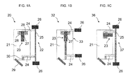
- FIG. 3 shows a schematic view of a first exemplary embodiment of an arrangement 20 according to the invention comprising a door leaf 21 and a drive device 22 for moving the door leaf 21 for an outer swinging door of a passenger transport vehicle (not shown)
- the drive device 22 comprises a motor 23, in particular an electric motor, an upper and lower support arm 24 and a portal-side rotary column 25.
- the rotary column 25 is rotatably supported by means of vehicle-side bearing 26 on passenger transport vehicle.
- the door leaf 21 is articulated about the support arms 24, the rotary column 25 and the vehicle-side bearings 26, in particular rotatable or pivotable, attached to the passenger transport vehicle.
- drive shaft is fixed by door-side bearing 28 on the door 21.
- the housing 27 of the motor 23, which constitutes a stationary component of the motor 23 with respect to the drive shaft, is fixedly connected to the door leaf 21 by means of the door-side bearings 28.
- the motor 23 is at least partially disposed in the volume encompassed by the door leaf 21.
- drive shaft of the motor 23 is connected to the door leaf-side end of the upper support arm 24. That is, the drive shaft of the motor 23 is supported in the in FIG. 1A shown embodiment of the upper support arm 24, the rotary column 25 and the vehicle-mounted bearings 26 on passenger transport vehicle.
- the door 21 of the swing door by means of a in the FIG. 1A schematically shown guide 29 and a steering linkage 29 guided in a manner known per se for an outdoor swing door on the passenger transport vehicle.
- the door leaf 21 of the outer swing door opens outwardly in a movement of the drive device 22 parallel to the passenger transport vehicle, wherein the movement of the door leaf 21 between the closed and the open position is additionally controlled by means of the guide 29.
- the drive device 22 and thus the door leaf 21 moves via the support arms 24 under the influence of the guide 29 relative to the vehicle-side bearings 26 and the outer swinging door opens or closes.
- the lower support arm 24 is connected via a known per se door storage 30 with the door leaf 21.
- a second embodiment of an arrangement 32 according to the invention consists of a door leaf 21 and a drive device 33 for moving the door leaf 21 for an outer swinging door of a passenger transport vehicle, not shown FIG. 1B
- the arrangement 32 differs from that in FIG. 1A shown arrangement 20 substantially only by the drive device 33, wherein the in FIG. 1A shown portal-side rotary column 25 is omitted.
- the support arms 24 of the assembly 32 are now connected to the vehicle-side bearings 26 so that the drive shaft of the motor 23, which is connected to the door leaf-side end of the upper support arm 24, in the in FIG. 1B shown embodiment on the support arm 24 and the vehicle-side bearing 26 is supported on the passenger transport vehicle.
- the motor 23 is arranged at least partially in the volume enclosed by the door leaf 21 in order to obtain a particularly compact and space-saving arrangement 32.
- FIG. 1C is a schematic view of a third embodiment of an inventive arrangement 36 of a door 21 and a drive device 37 for a swing door of a passenger transport vehicle shown.
- the arrangement 36 differs from that in FIG. 1A shown arrangement 20 substantially only by the drive device 37 at the installation position of the motor 23 is changed.
- the motor 23 is in the arrangement 36 via an in FIG. 1C not shown in detail angle gear connected to the upper arm 24.
- the drive shaft of the motor 23 is connected to the door-leaf-side end of the upper support arm, so that the drive shaft via the bevel gear, the upper support arm 24, the portal-side pivot column 25 and the vehicle-side bearing 26 is supported on the passenger transport vehicle.
- the motor 23 is also arranged at least partially in the volume encompassed by the door leaf 21 in order to obtain a particularly compact and space-saving arrangement 36.
- FIG. 1D is a schematic view of a fourth embodiment of an inventive arrangement 40 of a door 21 and a drive device 41 for a swing door of a passenger transport vehicle shown.
- the arrangement 41 differs from that in FIG. 1A shown assembly 20 substantially only by the drive device 41, wherein the drive shaft of the motor 23 drives the door leaf 21 and means for hinged mounting of the housing 27 are provided on passenger transport vehicle.
- the motor 23 and the housing 27, as FIG. 1D can be seen in the illustrated embodiment, attached to the upper support arm 24 and in this case preferably at least partially disposed in the volume encompassed by the support arm 24.
- the upper support arm 24 is, as already in connection with the FIG.
- FIG. 1D can also be seen, the mounting position of the motor 23 in the arrangement 40 relative to the installation position of the motor 23 in the arrangement 20 of FIG. 1A also changed.
- the motor 23 is in the arrangement 41 via an in FIG. 1D not shown in detail angle gear with the door 21 and connected to the associated door leaf 21 door mounting 30. In this way, a flexible arrangement of the motor 23 on the support arm 24 is possible.
- a fifth exemplary embodiment of an arrangement 44 according to the invention consists of a door leaf 21 and a drive device 45 for moving the door leaf 21 for an external swinging door of a passenger transport vehicle, not shown FIG. 1E
- the arrangement 44 differs from that in FIG. 1D shown arrangement 40 substantially only by the drive device 45, in which the in FIG. 1D shown portal-side rotary column 25 is omitted.
- the support arms 24 of the assembly 45 are now connected to the vehicle-side bearings 26.
- the motor 23 and the housing 27 of the motor 23 is fixedly connected to the upper support arm 24, so that the housing 27 of the motor 23 via the support arm 24 and the bearing 26 is pivotally, in particular rotatable or pivotally connected to the passenger transport vehicle ,
- the motor 23 is arranged at least partially in the volume encompassed by the support arm 24 in order to obtain a particularly compact and space-saving arrangement 44.
- FIG. 1F is a schematic view of a sixth embodiment of an inventive arrangement 48 of a door 21 and a drive device 49 for a swing door of a passenger transport vehicle shown.
- the motor 23 and the housing 27 is attached to the upper support arm 24.
- the drive shaft is supported by a in FIG. 1F Now, the drive shaft is rotated, the support arm 24 and thus also the door 21 moves by means of the guide 29 relative to the vehicle-side bearings 26.
- the motor 23 at least partially disposed in the volume encompassed by the upper support arm 24 in order to obtain a particularly compact and space-saving arrangement 48.
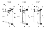
- FIG. 2A to 2F represent in each case seventh to twelfth embodiments of inventive arrangements 52, 56, 60, 64, 68 and 72 for inner swing doors.
- the representations of FIG. 2A to 2F correspond with the representations of the FIG. 1A to 1F with the difference that the respective drive devices 53, 57, 61, 65, 69, and 73 of the FIG. 2A to 2F Driving inside swing doors instead of external swing doors as in the FIG. 1A to 1F , Inner swinging doors pivot by means of a guide rail and guide roller, which are in the FIG. 2A to 2F at the reference numeral 54 is shown schematically when opening at approximately 90 ° in the interior of the passenger transport vehicle.
- FIG. 3 shows a schematic view of a seventh exemplary embodiment of an arrangement 52 according to the invention comprising a door leaf 21 and a drive device 53 for moving the door leaf 21 for an inner swinging door of a passenger transport vehicle (not shown)
- the drive device 53 comprises a motor 23, in particular an electric motor, an upper and lower support arm 24 and a portal-side rotary column 25.
- the rotary column 25 is rotatably supported by means of vehicle-side bearing 26 on passenger transport vehicle.
- the door leaf 21 is articulated about the support arms 24, the rotary column 25 and the vehicle-side bearings 26, in particular rotatable or pivotable, attached to the passenger transport vehicle.
- drive shaft is fixed by door-side bearing 28 on the door 21.
- the housing 27 of the motor 23, which constitutes a stationary component of the motor 23 with respect to the drive shaft, is fixedly connected to the door leaf 21 by means of the door-side bearings 28.
- the motor 23 is at least partially disposed in the volume encompassed by the door leaf 21.
- drive shaft of the motor 23 is connected to the door leaf-side end of the upper support arm 24. That is, the drive shaft of the motor 23 is supported in the in FIG. 2A shown embodiment of the upper support arm 24, the rotary column 25 and the vehicle-mounted bearings 26 on passenger transport vehicle.
- the drive device 53 and thus the door leaf 21 moves via the support arms 24 under the influence of the guide 54 relative to the vehicle-side bearings 26 and the inner swinging door opens or closes.
- the lower support arm 24 is connected via a known per se door storage 30 with the door leaf 21.
- An eighth exemplary embodiment of an arrangement 56 according to the invention consists of a door leaf 21 and a drive device 57 for moving the door leaf 21 for an inner swinging door of a passenger transport vehicle (not shown) FIG. 2 B
- the arrangement 56 differs from that in FIG. 2A shown arrangement 52 substantially only by the drive device 57, wherein the in FIG. 2A shown portal-side rotary column 25 is omitted.
- the support arms 24 of the assembly 57 are now connected to the vehicle-side bearings 26 so that the drive shaft of the motor 23, which is connected to the door leaf-side end of the upper support arm 24, in the in FIG. 2 B shown embodiment on the support arm 24 and the vehicle-side bearing 26 is supported on the passenger transport vehicle.
- the motor 23 is also arranged at least partially in the volume encompassed by the door leaf 21 in order to obtain a particularly compact and space-saving arrangement 56.
- FIG. 2C is a schematic view of a ninth embodiment of an inventive arrangement 60 of a door 21 and a drive device 61 for an inner swinging door of a passenger transport vehicle shown.
- the arrangement 61 differs from that in FIG. 2A shown arrangement 52 substantially only by the drive device 61, in which the mounting position of the motor 23 is changed.
- the motor 23 is in the arrangement 60 via an in FIG. 2C not shown in detail angle gear connected to the upper arm 24.
- the drive shaft of the motor 23 is connected to the door-leaf-side end of the upper support arm 24, so that the drive shaft via the bevel gear, the upper support arm 24, the portal-side pivot column 25 and the vehicle-side bearing 26 is supported on the passenger transport vehicle.
- the motor 23 is also at the arrangement 60 at least partially disposed in the volume encompassed by the door leaf 21 in order to obtain a particularly compact and space-saving arrangement 60.
- FIG. 2D is a schematic view of a tenth embodiment of an inventive arrangement 64 of a door 21 and a drive device 65 for an inner swinging door of a passenger transport vehicle shown.
- the arrangement 64 differs from that in FIG. 2A shown assembly 52 substantially only by the drive device 65, wherein the drive shaft of the motor 23 drives the door leaf 21 and means are provided for articulated mounting of the housing 27 on the passenger transport vehicle.
- the motor 23 and the housing 27, as FIG. 2D can be seen in the illustrated embodiment, attached to the upper support arm 24 and in this case preferably at least partially disposed in the volume encompassed by the support arm 24.
- the upper support arm 24 is, as already in connection with the FIG.
- FIG. 2D can also be seen, the installation position of the motor 23 in the arrangement 64 relative to the installation position of the motor 23 in the arrangement 52 of FIG. 2A also changed.
- the motor 23 is in the arrangement 65 via an in FIG. 2D not shown in detail angle gear with the door 21 and connected to the associated door leaf 21 door mounting 30. In this way, a flexible arrangement of the motor 23 on the support arm 24 is possible.
- An eleventh embodiment of an arrangement 68 according to the invention consists of a door leaf 21 and a drive device 69 for moving the door leaf 21 for an inner swinging door of a passenger transport vehicle, not shown FIG. 2E
- the arrangement 68 differs from that in FIG. 2D shown arrangement 64 substantially only by the drive device 69, wherein the in FIG. 2D shown portal-side rotary column 25 is omitted.
- FIG. 2E can be clearly seen, the support arms 24 of the assembly 68 are now connected to the vehicle-side bearings 26.
- the motor 23 and the housing 27 of the motor 23 is fixedly connected to the upper support arm 24, so that the housing 27 of the motor 23 via the support arm 24 and the bearing 26 is pivotally, in particular rotatable or pivotally connected to the passenger transport vehicle ,
- the motor 23 is at least partially disposed in the volume encompassed by the support arm 24 in order to obtain a particularly compact and space-saving arrangement 68.
- FIG. 2F is a schematic view of a twelfth embodiment of an inventive arrangement 72 of a door 21 and a drive device 73 for an inner swinging door of a passenger transport vehicle shown.
- the motor 23 and the housing 27 is attached to the upper support arm 24.
- the drive shaft is supported by a in FIG. 2F Now, the drive shaft is rotated, the support arm 24 and thus also the door 21 moves by means of the guide 54 relative to the vehicle-side bearings 26.
- the motor 23 at least partially disposed in the volume encompassed by the upper support arm 24 in order to obtain a particularly compact and space-saving arrangement 72.
- FIG. 12 shows a schematic view of a thirteenth embodiment of an arrangement 76 according to the invention comprising a door leaf 21 and a drive device 77 for moving the door leaf 21 for a revolving door of a passenger transport vehicle (not shown)
- the drive device 77 comprises a motor 23, in particular an electric motor.
- the motor 23 or the housing 27 of the motor 23 is firmly connected to the door leaf 21.
- drive shaft of the motor 23 is connected to the upper portal-side holder or bearing 77.
- the drive can also be connected directly to the portal and then rotates the door via the drive shaft 21.
- the installation position of the motor 23 can be influenced by a bevel gear.
- FIG. 12 shows a schematic view of a fourteenth embodiment of an arrangement 80 according to the invention comprising a door leaf 21 and a drive device 81 for moving the door leaf 21 for a folding door of a passenger transport vehicle (not shown).
- a folding door differs from that in FIG. 3 shown revolving door essentially only in that the folding door has two door leaves 21 which are hinged together.
- the second door 21 is connected to the rotating door 21 and is guided via a guide in a folding movement.
- the drive device 81 essentially comprises a motor 23, in particular an electric motor.
- the motor 23 or the housing 27 of the motor 23 is fixedly connected to a door leaf 21, the rotating door leaf 21.
- FIG. 12 shows a schematic view of a fourteenth embodiment of an arrangement 80 according to the invention comprising a door leaf 21 and a drive device 81 for moving the door leaf 21 for a folding door of a passenger transport vehicle (not shown).
- a folding door differs from that in FIG. 3 shown revolving door essentially only in that
- drive shaft of the motor 23 is connected to the upper portal-side holder or bearing 77. Now, if the drive shaft is rotated, the motor 23 and thus the door 21 moves around the axis of rotation of the portal bearing 77.
- the drive can also be connected directly to the portal and then rotates the door 21 via the drive shaft.
- the installation position of the motor 23 can be influenced via an angle gear.
- the motor always interacts with the upper support arm of the drive device.
- the motor may instead also interact with the lower support arm shown in the embodiments.
- the arrangement according to the invention consists of a door leaf and a drive device for moving the door leaf in a passenger transport vehicle, in particular in a passenger transport vehicle of public passenger transport.
Landscapes
- Power-Operated Mechanisms For Wings (AREA)
Applications Claiming Priority (1)
| Application Number | Priority Date | Filing Date | Title |
|---|---|---|---|
| DE201220100338 DE202012100338U1 (de) | 2012-02-01 | 2012-02-01 | Anordnung aus einem Türflügel und einer Antriebsvorrichtung zum Bewegen des Türflügels für ein Personenbeförderungsfahrzeug |
Publications (2)
| Publication Number | Publication Date |
|---|---|
| EP2623701A2 true EP2623701A2 (fr) | 2013-08-07 |
| EP2623701A3 EP2623701A3 (fr) | 2014-10-22 |
Family
ID=47683588
Family Applications (1)
| Application Number | Title | Priority Date | Filing Date |
|---|---|---|---|
| EP13153412.5A Withdrawn EP2623701A3 (fr) | 2012-02-01 | 2013-01-31 | Agencement composé d'un battant de porte et d'un dispositif d'entraînement pour déplacer le battant de porte pour un véhicule de transport de personnes |
Country Status (2)
| Country | Link |
|---|---|
| EP (1) | EP2623701A3 (fr) |
| DE (1) | DE202012100338U1 (fr) |
Families Citing this family (1)
| Publication number | Priority date | Publication date | Assignee | Title |
|---|---|---|---|---|
| DE202016102025U1 (de) * | 2016-04-18 | 2017-07-19 | Gebr. Bode Gmbh & Co. Kg | Anordnung mit Türflügel und Antriebsvorrichtung zum Bewegen des Türflügels für ein Personenbeförderungsfahrzeug |
Citations (4)
| Publication number | Priority date | Publication date | Assignee | Title |
|---|---|---|---|---|
| JPH05112130A (ja) * | 1991-10-22 | 1993-05-07 | Nissan Motor Co Ltd | 自動車用ドアの開閉装置 |
| EP1040979A2 (fr) | 1999-03-27 | 2000-10-04 | Gebrüder Bode GmbH & Co.KG | Porte coulissante et pivotante pour véhicules, notamment véhicules de transport urbain de personnes |
| DE202008007585U1 (de) | 2007-12-21 | 2009-04-30 | Gebr. Bode GmbH & Co. KG Fahrzeugtürsysteme | Antriebsvorrichtung für Ein-/Ausstiegsvorrichtungen |
| DE102010011094A1 (de) * | 2010-03-11 | 2010-10-14 | Daimler Ag | Lagerung einer Klappe an einem Aufbau eines Kraftwagens sowie Karosserie für einen solchen Kraftwagen |
Family Cites Families (8)
| Publication number | Priority date | Publication date | Assignee | Title |
|---|---|---|---|---|
| DE19833612A1 (de) * | 1998-07-25 | 2000-01-27 | Bayerische Motoren Werke Ag | Motorischer Antrieb für ein schwenkbares Karosserieteil, wie Fahrzeugtüre, Haube oder dergleichen |
| CN1308565C (zh) * | 2000-09-06 | 2007-04-04 | 斯坦利公司 | 改进的机动门装置 |
| DE10207041B4 (de) * | 2002-02-20 | 2013-03-14 | Bayerische Motoren Werke Aktiengesellschaft | Betätigungseinrichtung zum Verstellen einer schwenkbaren Kraftfahrzeugtür |
| GB0601673D0 (en) * | 2006-01-27 | 2006-03-08 | Delphi Tech Inc | Door operating mechanism |
| FR2907833A1 (fr) * | 2006-10-27 | 2008-05-02 | Plastic Omnium Cie | Ensemble de deux ouvrants et vehicule automobile |
| DE202007013895U1 (de) * | 2007-10-04 | 2009-02-19 | BROSE SCHLIEßSYSTEME GMBH & CO. KG | Antriebsanordnung zur motorischen Verstellung einer Kraftfahrzeugtür o.dgl. |
| FR2928169B1 (fr) * | 2008-02-29 | 2013-03-08 | Monteiro Victor Moises Goncalves | Ensemble d'ouverture et de fermeture motorisee pour ouvrant/battant |
| EP2261449B1 (fr) * | 2009-06-10 | 2012-08-01 | Swed Adaptation AB | Unité de bras oscillant pour la portière latérale d'un véhicule et voiture fournie avec cette unité de bras oscillant |
-
2012
- 2012-02-01 DE DE201220100338 patent/DE202012100338U1/de not_active Expired - Lifetime
-
2013
- 2013-01-31 EP EP13153412.5A patent/EP2623701A3/fr not_active Withdrawn
Patent Citations (4)
| Publication number | Priority date | Publication date | Assignee | Title |
|---|---|---|---|---|
| JPH05112130A (ja) * | 1991-10-22 | 1993-05-07 | Nissan Motor Co Ltd | 自動車用ドアの開閉装置 |
| EP1040979A2 (fr) | 1999-03-27 | 2000-10-04 | Gebrüder Bode GmbH & Co.KG | Porte coulissante et pivotante pour véhicules, notamment véhicules de transport urbain de personnes |
| DE202008007585U1 (de) | 2007-12-21 | 2009-04-30 | Gebr. Bode GmbH & Co. KG Fahrzeugtürsysteme | Antriebsvorrichtung für Ein-/Ausstiegsvorrichtungen |
| DE102010011094A1 (de) * | 2010-03-11 | 2010-10-14 | Daimler Ag | Lagerung einer Klappe an einem Aufbau eines Kraftwagens sowie Karosserie für einen solchen Kraftwagen |
Also Published As
| Publication number | Publication date |
|---|---|
| EP2623701A3 (fr) | 2014-10-22 |
| DE202012100338U1 (de) | 2013-05-02 |
Similar Documents
| Publication | Publication Date | Title |
|---|---|---|
| EP1587701B1 (fr) | Portière coulissante pivotante pour véhicules | |
| DE102015121030A1 (de) | Angetriebene ausfahrbare Spoileranordnung für Kraftfahrzeuge | |
| DE102009014869A1 (de) | Schiebe-Schwenktür | |
| EP0768442B1 (fr) | Arrêt continu pour porte de véhicule à moteur commandé par force auxiliaire | |
| EP1506103A1 (fr) | Dispositif de couverture pour le logement de capote d'un cabriolet | |
| DE102019114940A1 (de) | Scharnierbasierter Ausgleichsmechanismus | |
| DE102018129874A1 (de) | Schwenktür-Steuerverbindung | |
| EP1348830A2 (fr) | Entraínement pour battant | |
| EP1767389B1 (fr) | Porte pivotante-coulissante pour véhicules de transport de personnes | |
| EP2623701A2 (fr) | Agencement composé d'un battant de porte et d'un dispositif d'entraînement pour déplacer le battant de porte pour un véhicule de transport de personnes | |
| EP3960974A1 (fr) | Porte pivotante coulissante pour un véhicule, ainsi que colonne pivotante pour une porte pivotante coulissante | |
| EP1509666B1 (fr) | Systeme de commande a mecanisme d'actionnement a levier concu pour faire pivoter une porte ou une trappe de vehicule | |
| DE4314026A1 (de) | Schwenktüre für einen Personendurchgang | |
| DE102005062211A1 (de) | Fahrzeugtür, Türanordnung für ein Kraftfahrzeug, sowie Verfahren zum Öffnen einer Türscheibe und Öffnen einer Türanordnung | |
| WO2017182475A1 (fr) | Ensemble comprenant un vantail de porte et un mécanisme de commande pour mouvoir le vantail de porte, destiné à un véhicule de transport de passagers | |
| WO2015067491A2 (fr) | Mécanisme de hayon comportant un entraînement à broche | |
| DE102013202801B4 (de) | Einrichtung zur motorischen Betätigung einer Kraftfahrzeug-Türe mit Feststellfunktion | |
| EP1072747A2 (fr) | Dispositif d'entraínement pour le pivotement motorisé d'un panneau frontal ou d'un hayon de véhicule | |
| WO2005070716A1 (fr) | Dispositif pour actionner au moins un element exterieur pivotant d'un vehicule | |
| DE102008061395B4 (de) | Kraftfahrzeug mit Mechanismus zum Bewegen einer Klappe oder Scherentüre | |
| DE102004025075B4 (de) | Anordnung mit einer Faltdrehtür und Faltdrehtür | |
| DE102007024570A1 (de) | Scharnier für eine Kraftfahrzeugtür | |
| EP2801687B1 (fr) | Système de retenue d'une armoire comprenant un corps et un couvercle pliant articulé de façon mobile au niveau de celui-ci | |
| DE10225581A1 (de) | Vorrichtung zum Verschwenken einer Fahrzeugtür oder Fahrzeugklappe | |
| DE2606322C2 (de) | Betätigungsvorrichtung für eine Fahrzeugtür |
Legal Events
| Date | Code | Title | Description |
|---|---|---|---|
| PUAI | Public reference made under article 153(3) epc to a published international application that has entered the european phase |
Free format text: ORIGINAL CODE: 0009012 |
|
| AK | Designated contracting states |
Kind code of ref document: A2 Designated state(s): AL AT BE BG CH CY CZ DE DK EE ES FI FR GB GR HR HU IE IS IT LI LT LU LV MC MK MT NL NO PL PT RO RS SE SI SK SM TR |
|
| AX | Request for extension of the european patent |
Extension state: BA ME |
|
| PUAL | Search report despatched |
Free format text: ORIGINAL CODE: 0009013 |
|
| AK | Designated contracting states |
Kind code of ref document: A3 Designated state(s): AL AT BE BG CH CY CZ DE DK EE ES FI FR GB GR HR HU IE IS IT LI LT LU LV MC MK MT NL NO PL PT RO RS SE SI SK SM TR |
|
| AX | Request for extension of the european patent |
Extension state: BA ME |
|
| RIC1 | Information provided on ipc code assigned before grant |
Ipc: E05F 15/14 20060101ALI20140916BHEP Ipc: E05D 15/28 20060101ALN20140916BHEP Ipc: E05F 15/12 20060101AFI20140916BHEP Ipc: E05D 15/36 20060101ALN20140916BHEP |
|
| 17P | Request for examination filed |
Effective date: 20150422 |
|
| RBV | Designated contracting states (corrected) |
Designated state(s): AL AT BE BG CH CY CZ DE DK EE ES FI FR GB GR HR HU IE IS IT LI LT LU LV MC MK MT NL NO PL PT RO RS SE SI SK SM TR |
|
| 17Q | First examination report despatched |
Effective date: 20151007 |
|
| STAA | Information on the status of an ep patent application or granted ep patent |
Free format text: STATUS: THE APPLICATION IS DEEMED TO BE WITHDRAWN |
|
| 18D | Application deemed to be withdrawn |
Effective date: 20160419 |