EP2623740A2 - Procédé de transfert de carburant - Google Patents
Procédé de transfert de carburant Download PDFInfo
- Publication number
- EP2623740A2 EP2623740A2 EP13152596.6A EP13152596A EP2623740A2 EP 2623740 A2 EP2623740 A2 EP 2623740A2 EP 13152596 A EP13152596 A EP 13152596A EP 2623740 A2 EP2623740 A2 EP 2623740A2
- Authority
- EP
- European Patent Office
- Prior art keywords
- nozzle
- fuel
- fuel circuit
- main
- pilot
- Prior art date
- Legal status (The legal status is an assumption and is not a legal conclusion. Google has not performed a legal analysis and makes no representation as to the accuracy of the status listed.)
- Granted
Links
Images




Classifications
-
- F—MECHANICAL ENGINEERING; LIGHTING; HEATING; WEAPONS; BLASTING
- F02—COMBUSTION ENGINES; HOT-GAS OR COMBUSTION-PRODUCT ENGINE PLANTS
- F02C—GAS-TURBINE PLANTS; AIR INTAKES FOR JET-PROPULSION PLANTS; CONTROLLING FUEL SUPPLY IN AIR-BREATHING JET-PROPULSION PLANTS
- F02C7/00—Features, components parts, details or accessories, not provided for in, or of interest apart form groups F02C1/00 - F02C6/00; Air intakes for jet-propulsion plants
- F02C7/22—Fuel supply systems
- F02C7/236—Fuel delivery systems comprising two or more pumps
-
- F—MECHANICAL ENGINEERING; LIGHTING; HEATING; WEAPONS; BLASTING
- F02—COMBUSTION ENGINES; HOT-GAS OR COMBUSTION-PRODUCT ENGINE PLANTS
- F02C—GAS-TURBINE PLANTS; AIR INTAKES FOR JET-PROPULSION PLANTS; CONTROLLING FUEL SUPPLY IN AIR-BREATHING JET-PROPULSION PLANTS
- F02C3/00—Gas-turbine plants characterised by the use of combustion products as the working fluid
- F02C3/20—Gas-turbine plants characterised by the use of combustion products as the working fluid using a special fuel, oxidant, or dilution fluid to generate the combustion products
- F02C3/30—Adding water, steam or other fluids for influencing combustion, e.g. to obtain cleaner exhaust gases
-
- F—MECHANICAL ENGINEERING; LIGHTING; HEATING; WEAPONS; BLASTING
- F02—COMBUSTION ENGINES; HOT-GAS OR COMBUSTION-PRODUCT ENGINE PLANTS
- F02C—GAS-TURBINE PLANTS; AIR INTAKES FOR JET-PROPULSION PLANTS; CONTROLLING FUEL SUPPLY IN AIR-BREATHING JET-PROPULSION PLANTS
- F02C9/00—Controlling gas-turbine plants; Controlling fuel supply in air- breathing jet-propulsion plants
- F02C9/26—Control of fuel supply
- F02C9/40—Control of fuel supply specially adapted to the use of a special fuel or a plurality of fuels
-
- F—MECHANICAL ENGINEERING; LIGHTING; HEATING; WEAPONS; BLASTING
- F23—COMBUSTION APPARATUS; COMBUSTION PROCESSES
- F23D—BURNERS
- F23D11/00—Burners using a direct spraying action of liquid droplets or vaporised liquid into the combustion space
- F23D11/10—Burners using a direct spraying action of liquid droplets or vaporised liquid into the combustion space the spraying being induced by a gaseous medium, e.g. water vapour
-
- F—MECHANICAL ENGINEERING; LIGHTING; HEATING; WEAPONS; BLASTING
- F23—COMBUSTION APPARATUS; COMBUSTION PROCESSES
- F23K—FEEDING FUEL TO COMBUSTION APPARATUS
- F23K5/00—Feeding or distributing other fuel to combustion apparatus
- F23K5/02—Liquid fuel
- F23K5/14—Details thereof
-
- F—MECHANICAL ENGINEERING; LIGHTING; HEATING; WEAPONS; BLASTING
- F23—COMBUSTION APPARATUS; COMBUSTION PROCESSES
- F23K—FEEDING FUEL TO COMBUSTION APPARATUS
- F23K5/00—Feeding or distributing other fuel to combustion apparatus
- F23K5/02—Liquid fuel
- F23K5/14—Details thereof
- F23K5/18—Cleaning or purging devices, e.g. filters
-
- F—MECHANICAL ENGINEERING; LIGHTING; HEATING; WEAPONS; BLASTING
- F23—COMBUSTION APPARATUS; COMBUSTION PROCESSES
- F23D—BURNERS
- F23D2209/00—Safety arrangements
- F23D2209/30—Purging
-
- F—MECHANICAL ENGINEERING; LIGHTING; HEATING; WEAPONS; BLASTING
- F23—COMBUSTION APPARATUS; COMBUSTION PROCESSES
- F23D—BURNERS
- F23D2900/00—Special features of, or arrangements for burners using fluid fuels or solid fuels suspended in a carrier gas
- F23D2900/00016—Preventing or reducing deposit build-up on burner parts, e.g. from carbon
-
- F—MECHANICAL ENGINEERING; LIGHTING; HEATING; WEAPONS; BLASTING
- F23—COMBUSTION APPARATUS; COMBUSTION PROCESSES
- F23K—FEEDING FUEL TO COMBUSTION APPARATUS
- F23K2300/00—Pretreatment and supply of liquid fuel
- F23K2300/20—Supply line arrangements
-
- F—MECHANICAL ENGINEERING; LIGHTING; HEATING; WEAPONS; BLASTING
- F23—COMBUSTION APPARATUS; COMBUSTION PROCESSES
- F23N—REGULATING OR CONTROLLING COMBUSTION
- F23N2227/00—Ignition or checking
- F23N2227/02—Starting or ignition cycles
-
- F—MECHANICAL ENGINEERING; LIGHTING; HEATING; WEAPONS; BLASTING
- F23—COMBUSTION APPARATUS; COMBUSTION PROCESSES
- F23N—REGULATING OR CONTROLLING COMBUSTION
- F23N2227/00—Ignition or checking
- F23N2227/04—Prepurge
Definitions
- the subject matter disclosed herein relates to turbine engines, and more particularly to a method for transferring fuel for a turbine liquid fuel system.
- a combustion system typically employs multiple cans that are arranged circumferentially, with combustible fuel being delivered to each can for combustion.
- the liquid fuel is often injected through a nozzle with atomization air assistance. If the atomization air is not used, the nozzle itself will be the atomizer. In this case, the combustion efficiency is related to the nozzle tip pressure drop.
- the combustion system typically employs two different fuel circuits, such as a pilot and a main, for example, because the fuel flow range from light off to base load is rather large.
- a pilot for example
- a method for transferring fuel includes flowing water to at least one nozzle of a main fuel circuit. Also included is flowing oil to the at least one nozzle of the main fuel circuit. Further included is flowing liquid fuel to the at least one nozzle of the main fuel circuit, wherein flowing water to the at least one nozzle of the main fuel circuit occurs prior to flowing oil to the at least one nozzle of the main fuel circuit and flowing liquid fuel to the at least one nozzle of the main fuel circuit.
- a method for transferring fuel includes providing a pilot fuel circuit and a main fuel circuit to a combustion system, wherein the pilot fuel circuit and the main fuel circuit each comprise at least one nozzle. Also included is flowing pilot oil to the at least one nozzle of the pilot fuel circuit. Further included is flowing water to the at least one nozzle of the main fuel circuit. Yet further included is turning on the main fuel circuit, ramping up the main fuel circuit to a fixed position, and ramping down the pilot fuel circuit to a fixed position in about 10 seconds to about 40 seconds.
- a method for transferring fuel includes pre-filling a pilot manifold and a main manifold with oil. Also included is flowing oil to a plurality of nozzles of a pilot fuel circuit and ramping up a pilot control valve to about 80% to about 90% valve stroke. Further included is flowing water to a plurality of nozzles of a main fuel circuit. Yet further included is flowing oil to the plurality of nozzles of the main fuel circuit and ramping down the pilot fuel circuit. The method also includes flowing water to the plurality of nozzles of the pilot fuel circuit and operating under base load conditions.
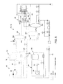
- FIG. 1 schematically illustrates a test set-up flow diagram for a gas turbine system 10.
- the gas turbine system 10 comprises a liquid fuel system 12 that is capable of transporting various fluids, such as oil, water, nitrogen, natural gas, and/or an emulsion. These are merely exemplary fluids that the liquid fuel system 12 is configured to operate with, and it is conceivable that other fluids may be employed within the liquid fuel system 12.
- the liquid fuel system 12 includes an oil source 14 comprising an oil tank 16 operably connected to an oil pump skid 18.
- the oil pump skid 18 includes an oil filter 20 and an oil centrifugal pump 22.
- the oil source 14 includes a plurality of oil lines 24 that operably connect the oil source 14 to a pilot fuel circuit 26 and a main fuel circuit 28, with each of the plurality of oil lines 24 containing various valves and flow meters to monitor and regulate flow within the plurality of oil lines 24.
- the liquid fuel system 12 also includes a water source 30 comprising a water tank 32 operably connected to a water pump skid 34.
- the water pump skid 34 includes a water filter 36 and a water centrifugal pump 38.
- the water flowing from the water source 30 is typically demineralized water, but other types of water may be employed.
- the water source 30 includes at least one water line 40 that operably connects the water source 30 to the pilot fuel circuit 26 and/or the main fuel circuit 28, with the at least one water line 40 containing various valves, flow meters, and possibly other components to monitor and regulate flow within the at least one water line 40.
- the pilot fuel circuit 26 comprises at least one pilot manifold (not illustrated), at least one pilot oil control valve 44, at least one pilot water valve 46, and at least one nozzle 47 through which combustible fuel may be transferred.
- the main fuel circuit 28 comprises at least one main manifold (not illustrated), at least one main oil control valve 50, at least one main water valve 52, and at least one nozzle 49 through which combustible fuel may be transferred.
- a mixing valve 48 is configured to deliver a mixture that includes combustible fuel to a combustor can (not illustrated).
- one aspect of the invention provides a method for operating the liquid fuel system 12 of the gas turbine system 10.
- a start-up method for the liquid fuel system initially includes starting various pumps, including the oil centrifugal pump 22 and the water centrifugal pump 38, as well as draining the main manifold of any water present. Subsequently, the main and pilot manifolds are each pre-filled with oil.
- the at least one, but typically a plurality of nozzles 47 associated with the pilot fuel circuit 26 begin to receive oil flow at a fixed valve position in order to facilitate light off flow.
- the oil flow through the pilot oil control valve 44 of the pilot fuel circuit 26 may then be switched to flow control and ramped up to about 80% to about 90% valve stroke.
- the main water valve 52 may be opened in order to initiate water flow to the at least one, but typically a plurality of nozzles 49 of the main fuel circuit 28.
- the water flow to the at least one nozzle 49 may last for about five (5) to about ten (10) seconds.
- Flowing water to the at least one nozzle 49 of the main fuel circuit 28 protects the nozzle 49 from undesirable effects associated with initial oil flow thereto, such as coking buildup, for example.
- oil may begin to flow to the main fuel circuit 28, thereby resulting in the provision of fuel to the nozzle 49 of the main fuel circuit 28.
- the main oil control valve 50 is set at a fixed position and the pilot oil control valve 44 is ramped down to a fixed position in a timeframe of from about 10 seconds to about 40 seconds, depending on the application.
- the main oil control valve 50, the pilot oil control valve 44, and the main water valve 52 are switched to flow control and ramped up until system load conditions of about 50% to about 60% are satisfied, however, typically about a 60% load will be met.
- system load conditions of about 50% to about 60% are satisfied, however, typically about a 60% load will be met.
- water flows to the pilot fuel circuit 26 by opening of the pilot water valve 46.
- the fuel and water flow continue to ramp up toward full load, with a desired water/oil ratio of about in the range of about 0.9 to about 1.4.
- the system then operates at base load.
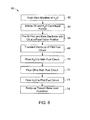
- a startup sequence comprises draining the main manifold of water 62 and initiating the oil centrifugal pump and the water centrifugal pump 64.
- the pilot manifold of the pilot fuel circuit and the main manifold of the main fuel circuit are pre-filled with oil 66 at a flow resulting from a fixed valve position of the pilot oil control valve.
- the fixed valve position of the pilot oil control valve is then switched to a flow control operation during a transient ramp up process 68 of the pilot fuel circuit.
- the transient ramp up process 68 continues in the flow control operation until reaching about 80% to about 90% valve stroke of the pilot oil control valve.
- the main water valve is opened to initiate water flow 70 to at least one nozzle of the main fuel circuit.
- the water flow to the at least one nozzle lasts for about five (5) to about ten (10) seconds.
- oil flows to the main fuel circuit 72.
- the main oil control valve is set at a fixed position and the pilot oil control valve is ramped down to a fixed position in a timeframe of from about 10 seconds to about 40 seconds, thereby resulting in the pilot control valve reaching about 20% to about 35% valve stroke.
- the main oil control valve, the pilot oil control valve, and the main water valve are switched for flow control and ramped up until system load conditions of about 50% to about 60% are met, which may coincide with a main fuel flow rate of from about 14 lbs/second to about 35 lbs/second.
- Water then flows to the pilot fuel circuit 74 by opening of the pilot water valve.
- the fuel and water flow continue to ramp up toward full load 76, with a desired water/oil ratio of about 0.9 to 1.4.
- the system then is operated at base load.
- the method enables the dual circuit, two stage design without requiring atomization air assistance, instead relying on the nozzles as atomizers.
- the nozzles are protected from coking buildup that inhibits effective fuel transfer, thereby leading to more efficient combustion.
Landscapes
- Engineering & Computer Science (AREA)
- Chemical & Material Sciences (AREA)
- Combustion & Propulsion (AREA)
- Mechanical Engineering (AREA)
- General Engineering & Computer Science (AREA)
- Feeding And Controlling Fuel (AREA)
- Fuel-Injection Apparatus (AREA)
- Engine Equipment That Uses Special Cycles (AREA)
Applications Claiming Priority (1)
| Application Number | Priority Date | Filing Date | Title |
|---|---|---|---|
| US13/362,059 US8991190B2 (en) | 2012-01-31 | 2012-01-31 | Fuel nozzle staging with water flowing prior to fuel in a main fuel circuit during start-up |
Publications (3)
| Publication Number | Publication Date |
|---|---|
| EP2623740A2 true EP2623740A2 (fr) | 2013-08-07 |
| EP2623740A3 EP2623740A3 (fr) | 2018-04-11 |
| EP2623740B1 EP2623740B1 (fr) | 2020-09-23 |
Family
ID=47631315
Family Applications (1)
| Application Number | Title | Priority Date | Filing Date |
|---|---|---|---|
| EP13152596.6A Active EP2623740B1 (fr) | 2012-01-31 | 2013-01-24 | Procédé de transfert de carburant |
Country Status (5)
| Country | Link |
|---|---|
| US (1) | US8991190B2 (fr) |
| EP (1) | EP2623740B1 (fr) |
| JP (1) | JP6283166B2 (fr) |
| CN (1) | CN103225547B (fr) |
| RU (1) | RU2604152C2 (fr) |
Cited By (1)
| Publication number | Priority date | Publication date | Assignee | Title |
|---|---|---|---|---|
| WO2020242556A1 (fr) * | 2019-05-30 | 2020-12-03 | Siemens Aktiengesellschaft | Injection d'eau de turbine à gaz pour la réduction d'émissions |
Families Citing this family (3)
| Publication number | Priority date | Publication date | Assignee | Title |
|---|---|---|---|---|
| JP6235297B2 (ja) * | 2013-10-16 | 2017-11-22 | 日本化薬株式会社 | 液晶シール剤及びそれを用いた液晶表示セル |
| CN106062315B (zh) * | 2013-12-09 | 2017-12-26 | 西门子股份公司 | 具有用于改进的燃料管线冲刷的旁通管线的燃气轮机以及用于冲刷燃气轮机的方法 |
| CN115750110A (zh) * | 2021-08-26 | 2023-03-07 | 中国航发商用航空发动机有限责任公司 | 发动机的燃油控制方法、装置、电子设备、存储介质 |
Family Cites Families (21)
| Publication number | Priority date | Publication date | Assignee | Title |
|---|---|---|---|---|
| EP0420599B1 (fr) * | 1989-09-29 | 1995-06-21 | Ortech Corporation | Système de commande d'écoulement |
| US5175994A (en) * | 1991-05-03 | 1993-01-05 | United Technologies Corporation | Combustion section supply system having fuel and water injection for a rotary machine |
| US5344306A (en) | 1991-08-28 | 1994-09-06 | Nalco Fuel Tech | Reducing nitrogen oxides emissions by dual fuel firing of a turbine |
| DE59710054D1 (de) * | 1997-11-10 | 2003-06-12 | Alstom Switzerland Ltd | Verfahren zur Überwachung des Versorgungssystems einer Gasturbine mit Mehrbrennersystem sowie Vorrichtung zur Durchführung des Verfahrens |
| DE59810159D1 (de) * | 1998-02-26 | 2003-12-18 | Alstom Switzerland Ltd | Verfahren zum sicheren Entfernen von Flüssigbrennstoff aus dem Brennstoffsystem einer Gasturbine sowie Vorrichtung zur Durchführung des Verfahrens |
| EP0952317A3 (fr) * | 1998-04-21 | 2002-04-17 | Mitsubishi Heavy Industries, Ltd. | Système de purge pour l'alimentation en carburant d'une turbine à gaz |
| EP1199453A3 (fr) * | 1998-05-08 | 2003-01-22 | Mitsubishi Heavy Industries, Ltd. | Système de lavage des injecteurs de carburant d'une turbine à gaz |
| JP2000054857A (ja) * | 1998-08-10 | 2000-02-22 | Hitachi Ltd | ガスタービン |
| RU2139917C1 (ru) * | 1998-10-15 | 1999-10-20 | Борис Борисович Булгаков | Способ получения котельного топлива и устройство для его осуществления |
| US6206684B1 (en) * | 1999-01-22 | 2001-03-27 | Clean Energy Systems, Inc. | Steam generator injector |
| JP4317628B2 (ja) * | 1999-06-15 | 2009-08-19 | 三菱重工業株式会社 | ガスタービン燃焼器の油ノズルパージ方法 |
| US6715295B2 (en) * | 2002-05-22 | 2004-04-06 | Siemens Westinghouse Power Corporation | Gas turbine pilot burner water injection and method of operation |
| JP4659543B2 (ja) * | 2005-07-13 | 2011-03-30 | 株式会社日立製作所 | ガスタービン燃焼器、その燃料のカーボン化防止方法及びパージ方法 |
| JP4119909B2 (ja) * | 2005-09-14 | 2008-07-16 | 三菱重工業株式会社 | ガスタービンの燃焼制御装置 |
| JP2008031847A (ja) * | 2006-07-26 | 2008-02-14 | Hitachi Ltd | ガスタービン燃焼器とその運転方法、及びガスタービン燃焼器の改造方法 |
| US8820087B2 (en) * | 2008-09-08 | 2014-09-02 | Siemens Energy, Inc. | Method and system for controlling fuel to a dual stage nozzle |
| EP2379944B1 (fr) * | 2008-12-19 | 2019-08-07 | Ansaldo Energia S.p.A. | Procede de fourniture d'une installation de turbine a gaz et installation de turbine a gaz |
| US8381529B2 (en) * | 2009-01-29 | 2013-02-26 | General Electric Company | System and method for water injection in a turbine engine |
| CN101949589A (zh) * | 2010-09-07 | 2011-01-19 | 梁应开 | 一种燃气热水器阀体总成 |
| US8973366B2 (en) * | 2011-10-24 | 2015-03-10 | General Electric Company | Integrated fuel and water mixing assembly for use in conjunction with a combustor |
| US9188061B2 (en) * | 2011-10-24 | 2015-11-17 | General Electric Company | System for turbine combustor fuel assembly |
-
2012
- 2012-01-31 US US13/362,059 patent/US8991190B2/en active Active
-
2013
- 2013-01-24 EP EP13152596.6A patent/EP2623740B1/fr active Active
- 2013-01-29 RU RU2013103752/06A patent/RU2604152C2/ru not_active IP Right Cessation
- 2013-01-29 JP JP2013013818A patent/JP6283166B2/ja active Active
- 2013-01-31 CN CN201310038978.2A patent/CN103225547B/zh active Active
Non-Patent Citations (1)
| Title |
|---|
| None |
Cited By (4)
| Publication number | Priority date | Publication date | Assignee | Title |
|---|---|---|---|---|
| WO2020242556A1 (fr) * | 2019-05-30 | 2020-12-03 | Siemens Aktiengesellschaft | Injection d'eau de turbine à gaz pour la réduction d'émissions |
| CN114041006A (zh) * | 2019-05-30 | 2022-02-11 | 西门子能源全球有限两合公司 | 用于减排的燃气涡轮机注水 |
| CN114041006B (zh) * | 2019-05-30 | 2024-03-29 | 西门子能源全球有限两合公司 | 用于减排的燃气涡轮机注水 |
| US11952940B2 (en) | 2019-05-30 | 2024-04-09 | Siemens Energy Global GmbH & Co. KG | Gas turbine water injection for emissions reduction |
Also Published As
| Publication number | Publication date |
|---|---|
| JP2013155738A (ja) | 2013-08-15 |
| US20130192236A1 (en) | 2013-08-01 |
| CN103225547B (zh) | 2017-04-12 |
| EP2623740A3 (fr) | 2018-04-11 |
| EP2623740B1 (fr) | 2020-09-23 |
| RU2604152C2 (ru) | 2016-12-10 |
| RU2013103752A (ru) | 2014-08-10 |
| CN103225547A (zh) | 2013-07-31 |
| US8991190B2 (en) | 2015-03-31 |
| JP6283166B2 (ja) | 2018-02-21 |
Similar Documents
| Publication | Publication Date | Title |
|---|---|---|
| US9926861B2 (en) | Two-fuel injection system and implementation method using same | |
| US8991190B2 (en) | Fuel nozzle staging with water flowing prior to fuel in a main fuel circuit during start-up | |
| RU2642938C2 (ru) | Ракетный двигатель в сборе | |
| US9303562B2 (en) | Methods and systems for operating gas turbine engines | |
| US8783007B2 (en) | Liquid fuel system and method | |
| EP3147484B1 (fr) | Procédé et système de transfert fiable de l'état gazeux à l'état liquide | |
| US10156192B2 (en) | Gas turbine engine with a multiple fuel delivery system | |
| EP3839228B1 (fr) | Système et procédés d'allumage et de fonctionnement d'un moteur à turbine à gaz avec des combustibles alternatifs | |
| US20140352314A1 (en) | Gas turbine engine fuel system with ecology valve | |
| US10563588B2 (en) | Fuel system with vacuum generator to purge fuel from fuel nozzles | |
| EP3473835B1 (fr) | Élimination d'oxygène en deux étapes pour un système de carburant de moteur de turbine à gaz | |
| US20110314833A1 (en) | Additive injection system for use with a turbine engine and methods of assembling same | |
| US20110083441A1 (en) | System and method for distributing fuel in a turbomachine | |
| CN106168383A (zh) | 燃气涡轮发动机液体燃料供给系统和方法 | |
| EP3205857A1 (fr) | Système et procédé de vidange de carburant | |
| CN106150798A (zh) | 低压燃料供给系统 | |
| US20220235708A1 (en) | Aircraft turbomachine comprising means for priming the lubricating pump | |
| US20170191423A1 (en) | Systems and methods for mitigating the impact of vanadium in heavy fuel oil | |
| JP2016118196A (ja) | 燃料パージシステム及びパージの方法 | |
| US20020192082A1 (en) | Method for the fuel supply and a fuel supply system for aircraft equipped with at least one aero gas turbine | |
| US12523171B2 (en) | Flash-atomizing ammonia in a gas turbine combustor | |
| EP4520944A1 (fr) | Systèmes de pompe à déplacement variable (vdp) avec pompe principale centrifuge à sec | |
| CN102312727A (zh) | 用于涡轮发动机的添加剂喷射系统及其组装方法 |
Legal Events
| Date | Code | Title | Description |
|---|---|---|---|
| PUAI | Public reference made under article 153(3) epc to a published international application that has entered the european phase |
Free format text: ORIGINAL CODE: 0009012 |
|
| AK | Designated contracting states |
Kind code of ref document: A2 Designated state(s): AL AT BE BG CH CY CZ DE DK EE ES FI FR GB GR HR HU IE IS IT LI LT LU LV MC MK MT NL NO PL PT RO RS SE SI SK SM TR |
|
| AX | Request for extension of the european patent |
Extension state: BA ME |
|
| PUAL | Search report despatched |
Free format text: ORIGINAL CODE: 0009013 |
|
| AK | Designated contracting states |
Kind code of ref document: A3 Designated state(s): AL AT BE BG CH CY CZ DE DK EE ES FI FR GB GR HR HU IE IS IT LI LT LU LV MC MK MT NL NO PL PT RO RS SE SI SK SM TR |
|
| AX | Request for extension of the european patent |
Extension state: BA ME |
|
| RIC1 | Information provided on ipc code assigned before grant |
Ipc: F23K 5/14 20060101ALI20180308BHEP Ipc: F23D 11/10 20060101ALI20180308BHEP Ipc: F02C 7/236 20060101ALI20180308BHEP Ipc: F02C 3/30 20060101AFI20180308BHEP Ipc: F02C 9/40 20060101ALI20180308BHEP |
|
| STAA | Information on the status of an ep patent application or granted ep patent |
Free format text: STATUS: REQUEST FOR EXAMINATION WAS MADE |
|
| 17P | Request for examination filed |
Effective date: 20181011 |
|
| RBV | Designated contracting states (corrected) |
Designated state(s): AL AT BE BG CH CY CZ DE DK EE ES FI FR GB GR HR HU IE IS IT LI LT LU LV MC MK MT NL NO PL PT RO RS SE SI SK SM TR |
|
| STAA | Information on the status of an ep patent application or granted ep patent |
Free format text: STATUS: EXAMINATION IS IN PROGRESS |
|
| 17Q | First examination report despatched |
Effective date: 20191015 |
|
| GRAP | Despatch of communication of intention to grant a patent |
Free format text: ORIGINAL CODE: EPIDOSNIGR1 |
|
| STAA | Information on the status of an ep patent application or granted ep patent |
Free format text: STATUS: GRANT OF PATENT IS INTENDED |
|
| INTG | Intention to grant announced |
Effective date: 20200422 |
|
| GRAS | Grant fee paid |
Free format text: ORIGINAL CODE: EPIDOSNIGR3 |
|
| GRAA | (expected) grant |
Free format text: ORIGINAL CODE: 0009210 |
|
| STAA | Information on the status of an ep patent application or granted ep patent |
Free format text: STATUS: THE PATENT HAS BEEN GRANTED |
|
| AK | Designated contracting states |
Kind code of ref document: B1 Designated state(s): AL AT BE BG CH CY CZ DE DK EE ES FI FR GB GR HR HU IE IS IT LI LT LU LV MC MK MT NL NO PL PT RO RS SE SI SK SM TR |
|
| REG | Reference to a national code |
Ref country code: GB Ref legal event code: FG4D |
|
| REG | Reference to a national code |
Ref country code: CH Ref legal event code: EP |
|
| REG | Reference to a national code |
Ref country code: DE Ref legal event code: R096 Ref document number: 602013072698 Country of ref document: DE |
|
| REG | Reference to a national code |
Ref country code: IE Ref legal event code: FG4D |
|
| REG | Reference to a national code |
Ref country code: AT Ref legal event code: REF Ref document number: 1316588 Country of ref document: AT Kind code of ref document: T Effective date: 20201015 |
|
| PG25 | Lapsed in a contracting state [announced via postgrant information from national office to epo] |
Ref country code: HR Free format text: LAPSE BECAUSE OF FAILURE TO SUBMIT A TRANSLATION OF THE DESCRIPTION OR TO PAY THE FEE WITHIN THE PRESCRIBED TIME-LIMIT Effective date: 20200923 Ref country code: SE Free format text: LAPSE BECAUSE OF FAILURE TO SUBMIT A TRANSLATION OF THE DESCRIPTION OR TO PAY THE FEE WITHIN THE PRESCRIBED TIME-LIMIT Effective date: 20200923 Ref country code: BG Free format text: LAPSE BECAUSE OF FAILURE TO SUBMIT A TRANSLATION OF THE DESCRIPTION OR TO PAY THE FEE WITHIN THE PRESCRIBED TIME-LIMIT Effective date: 20201223 Ref country code: NO Free format text: LAPSE BECAUSE OF FAILURE TO SUBMIT A TRANSLATION OF THE DESCRIPTION OR TO PAY THE FEE WITHIN THE PRESCRIBED TIME-LIMIT Effective date: 20201223 Ref country code: GR Free format text: LAPSE BECAUSE OF FAILURE TO SUBMIT A TRANSLATION OF THE DESCRIPTION OR TO PAY THE FEE WITHIN THE PRESCRIBED TIME-LIMIT Effective date: 20201224 Ref country code: FI Free format text: LAPSE BECAUSE OF FAILURE TO SUBMIT A TRANSLATION OF THE DESCRIPTION OR TO PAY THE FEE WITHIN THE PRESCRIBED TIME-LIMIT Effective date: 20200923 |
|
| REG | Reference to a national code |
Ref country code: AT Ref legal event code: MK05 Ref document number: 1316588 Country of ref document: AT Kind code of ref document: T Effective date: 20200923 |
|
| PG25 | Lapsed in a contracting state [announced via postgrant information from national office to epo] |
Ref country code: RS Free format text: LAPSE BECAUSE OF FAILURE TO SUBMIT A TRANSLATION OF THE DESCRIPTION OR TO PAY THE FEE WITHIN THE PRESCRIBED TIME-LIMIT Effective date: 20200923 Ref country code: LV Free format text: LAPSE BECAUSE OF FAILURE TO SUBMIT A TRANSLATION OF THE DESCRIPTION OR TO PAY THE FEE WITHIN THE PRESCRIBED TIME-LIMIT Effective date: 20200923 |
|
| REG | Reference to a national code |
Ref country code: NL Ref legal event code: MP Effective date: 20200923 |
|
| REG | Reference to a national code |
Ref country code: LT Ref legal event code: MG4D |
|
| PG25 | Lapsed in a contracting state [announced via postgrant information from national office to epo] |
Ref country code: SM Free format text: LAPSE BECAUSE OF FAILURE TO SUBMIT A TRANSLATION OF THE DESCRIPTION OR TO PAY THE FEE WITHIN THE PRESCRIBED TIME-LIMIT Effective date: 20200923 Ref country code: RO Free format text: LAPSE BECAUSE OF FAILURE TO SUBMIT A TRANSLATION OF THE DESCRIPTION OR TO PAY THE FEE WITHIN THE PRESCRIBED TIME-LIMIT Effective date: 20200923 Ref country code: PT Free format text: LAPSE BECAUSE OF FAILURE TO SUBMIT A TRANSLATION OF THE DESCRIPTION OR TO PAY THE FEE WITHIN THE PRESCRIBED TIME-LIMIT Effective date: 20210125 Ref country code: NL Free format text: LAPSE BECAUSE OF FAILURE TO SUBMIT A TRANSLATION OF THE DESCRIPTION OR TO PAY THE FEE WITHIN THE PRESCRIBED TIME-LIMIT Effective date: 20200923 Ref country code: LT Free format text: LAPSE BECAUSE OF FAILURE TO SUBMIT A TRANSLATION OF THE DESCRIPTION OR TO PAY THE FEE WITHIN THE PRESCRIBED TIME-LIMIT Effective date: 20200923 Ref country code: EE Free format text: LAPSE BECAUSE OF FAILURE TO SUBMIT A TRANSLATION OF THE DESCRIPTION OR TO PAY THE FEE WITHIN THE PRESCRIBED TIME-LIMIT Effective date: 20200923 Ref country code: CZ Free format text: LAPSE BECAUSE OF FAILURE TO SUBMIT A TRANSLATION OF THE DESCRIPTION OR TO PAY THE FEE WITHIN THE PRESCRIBED TIME-LIMIT Effective date: 20200923 |
|
| PG25 | Lapsed in a contracting state [announced via postgrant information from national office to epo] |
Ref country code: ES Free format text: LAPSE BECAUSE OF FAILURE TO SUBMIT A TRANSLATION OF THE DESCRIPTION OR TO PAY THE FEE WITHIN THE PRESCRIBED TIME-LIMIT Effective date: 20200923 Ref country code: AT Free format text: LAPSE BECAUSE OF FAILURE TO SUBMIT A TRANSLATION OF THE DESCRIPTION OR TO PAY THE FEE WITHIN THE PRESCRIBED TIME-LIMIT Effective date: 20200923 Ref country code: AL Free format text: LAPSE BECAUSE OF FAILURE TO SUBMIT A TRANSLATION OF THE DESCRIPTION OR TO PAY THE FEE WITHIN THE PRESCRIBED TIME-LIMIT Effective date: 20200923 Ref country code: IS Free format text: LAPSE BECAUSE OF FAILURE TO SUBMIT A TRANSLATION OF THE DESCRIPTION OR TO PAY THE FEE WITHIN THE PRESCRIBED TIME-LIMIT Effective date: 20210123 Ref country code: PL Free format text: LAPSE BECAUSE OF FAILURE TO SUBMIT A TRANSLATION OF THE DESCRIPTION OR TO PAY THE FEE WITHIN THE PRESCRIBED TIME-LIMIT Effective date: 20200923 |
|
| REG | Reference to a national code |
Ref country code: DE Ref legal event code: R097 Ref document number: 602013072698 Country of ref document: DE |
|
| PG25 | Lapsed in a contracting state [announced via postgrant information from national office to epo] |
Ref country code: SK Free format text: LAPSE BECAUSE OF FAILURE TO SUBMIT A TRANSLATION OF THE DESCRIPTION OR TO PAY THE FEE WITHIN THE PRESCRIBED TIME-LIMIT Effective date: 20200923 |
|
| PLBE | No opposition filed within time limit |
Free format text: ORIGINAL CODE: 0009261 |
|
| STAA | Information on the status of an ep patent application or granted ep patent |
Free format text: STATUS: NO OPPOSITION FILED WITHIN TIME LIMIT |
|
| PG25 | Lapsed in a contracting state [announced via postgrant information from national office to epo] |
Ref country code: DK Free format text: LAPSE BECAUSE OF FAILURE TO SUBMIT A TRANSLATION OF THE DESCRIPTION OR TO PAY THE FEE WITHIN THE PRESCRIBED TIME-LIMIT Effective date: 20200923 Ref country code: MC Free format text: LAPSE BECAUSE OF FAILURE TO SUBMIT A TRANSLATION OF THE DESCRIPTION OR TO PAY THE FEE WITHIN THE PRESCRIBED TIME-LIMIT Effective date: 20200923 Ref country code: SI Free format text: LAPSE BECAUSE OF FAILURE TO SUBMIT A TRANSLATION OF THE DESCRIPTION OR TO PAY THE FEE WITHIN THE PRESCRIBED TIME-LIMIT Effective date: 20200923 |
|
| REG | Reference to a national code |
Ref country code: CH Ref legal event code: PL |
|
| 26N | No opposition filed |
Effective date: 20210624 |
|
| GBPC | Gb: european patent ceased through non-payment of renewal fee |
Effective date: 20210124 |
|
| PG25 | Lapsed in a contracting state [announced via postgrant information from national office to epo] |
Ref country code: LU Free format text: LAPSE BECAUSE OF NON-PAYMENT OF DUE FEES Effective date: 20210124 |
|
| REG | Reference to a national code |
Ref country code: BE Ref legal event code: MM Effective date: 20210131 |
|
| PG25 | Lapsed in a contracting state [announced via postgrant information from national office to epo] |
Ref country code: FR Free format text: LAPSE BECAUSE OF NON-PAYMENT OF DUE FEES Effective date: 20210131 |
|
| PG25 | Lapsed in a contracting state [announced via postgrant information from national office to epo] |
Ref country code: LI Free format text: LAPSE BECAUSE OF NON-PAYMENT OF DUE FEES Effective date: 20210131 Ref country code: GB Free format text: LAPSE BECAUSE OF NON-PAYMENT OF DUE FEES Effective date: 20210124 Ref country code: CH Free format text: LAPSE BECAUSE OF NON-PAYMENT OF DUE FEES Effective date: 20210131 |
|
| PG25 | Lapsed in a contracting state [announced via postgrant information from national office to epo] |
Ref country code: IE Free format text: LAPSE BECAUSE OF NON-PAYMENT OF DUE FEES Effective date: 20210124 |
|
| PG25 | Lapsed in a contracting state [announced via postgrant information from national office to epo] |
Ref country code: IS Free format text: LAPSE BECAUSE OF FAILURE TO SUBMIT A TRANSLATION OF THE DESCRIPTION OR TO PAY THE FEE WITHIN THE PRESCRIBED TIME-LIMIT Effective date: 20210123 |
|
| PG25 | Lapsed in a contracting state [announced via postgrant information from national office to epo] |
Ref country code: BE Free format text: LAPSE BECAUSE OF NON-PAYMENT OF DUE FEES Effective date: 20210131 |
|
| PG25 | Lapsed in a contracting state [announced via postgrant information from national office to epo] |
Ref country code: HU Free format text: LAPSE BECAUSE OF FAILURE TO SUBMIT A TRANSLATION OF THE DESCRIPTION OR TO PAY THE FEE WITHIN THE PRESCRIBED TIME-LIMIT; INVALID AB INITIO Effective date: 20130124 |
|
| PG25 | Lapsed in a contracting state [announced via postgrant information from national office to epo] |
Ref country code: CY Free format text: LAPSE BECAUSE OF FAILURE TO SUBMIT A TRANSLATION OF THE DESCRIPTION OR TO PAY THE FEE WITHIN THE PRESCRIBED TIME-LIMIT Effective date: 20200923 |
|
| REG | Reference to a national code |
Ref country code: DE Ref legal event code: R081 Ref document number: 602013072698 Country of ref document: DE Owner name: GENERAL ELECTRIC TECHNOLOGY GMBH, CH Free format text: FORMER OWNER: GENERAL ELECTRIC COMPANY, SCHENECTADY, NY, US |
|
| PG25 | Lapsed in a contracting state [announced via postgrant information from national office to epo] |
Ref country code: MK Free format text: LAPSE BECAUSE OF FAILURE TO SUBMIT A TRANSLATION OF THE DESCRIPTION OR TO PAY THE FEE WITHIN THE PRESCRIBED TIME-LIMIT Effective date: 20200923 |
|
| PG25 | Lapsed in a contracting state [announced via postgrant information from national office to epo] |
Ref country code: MT Free format text: LAPSE BECAUSE OF FAILURE TO SUBMIT A TRANSLATION OF THE DESCRIPTION OR TO PAY THE FEE WITHIN THE PRESCRIBED TIME-LIMIT Effective date: 20200923 |
|
| PG25 | Lapsed in a contracting state [announced via postgrant information from national office to epo] |
Ref country code: TR Free format text: LAPSE BECAUSE OF FAILURE TO SUBMIT A TRANSLATION OF THE DESCRIPTION OR TO PAY THE FEE WITHIN THE PRESCRIBED TIME-LIMIT Effective date: 20200923 |
|
| PGFP | Annual fee paid to national office [announced via postgrant information from national office to epo] |
Ref country code: DE Payment date: 20251217 Year of fee payment: 14 |
|
| PGFP | Annual fee paid to national office [announced via postgrant information from national office to epo] |
Ref country code: IT Payment date: 20260107 Year of fee payment: 14 |