EP2625701B1 - Dispositif de fixation libérable d'un conducteur à un boîtier de transformateur de courant - Google Patents
Dispositif de fixation libérable d'un conducteur à un boîtier de transformateur de courant Download PDFInfo
- Publication number
- EP2625701B1 EP2625701B1 EP11781459.0A EP11781459A EP2625701B1 EP 2625701 B1 EP2625701 B1 EP 2625701B1 EP 11781459 A EP11781459 A EP 11781459A EP 2625701 B1 EP2625701 B1 EP 2625701B1
- Authority
- EP
- European Patent Office
- Prior art keywords
- holding element
- current transformer
- transformer housing
- longitudinal axis
- electrical conductor
- Prior art date
- Legal status (The legal status is an assumption and is not a legal conclusion. Google has not performed a legal analysis and makes no representation as to the accuracy of the status listed.)
- Not-in-force
Links
Images

Classifications
-
- H—ELECTRICITY
- H01—ELECTRIC ELEMENTS
- H01R—ELECTRICALLY-CONDUCTIVE CONNECTIONS; STRUCTURAL ASSOCIATIONS OF A PLURALITY OF MUTUALLY-INSULATED ELECTRICAL CONNECTING ELEMENTS; COUPLING DEVICES; CURRENT COLLECTORS
- H01R4/00—Electrically-conductive connections between two or more conductive members in direct contact, i.e. touching one another; Means for effecting or maintaining such contact; Electrically-conductive connections having two or more spaced connecting locations for conductors and using contact members penetrating insulation
- H01R4/28—Clamped connections, spring connections
- H01R4/30—Clamped connections, spring connections utilising a screw or nut clamping member
- H01R4/36—Conductive members located under tip of screw
-
- H—ELECTRICITY
- H05—ELECTRIC TECHNIQUES NOT OTHERWISE PROVIDED FOR
- H05K—PRINTED CIRCUITS; CASINGS OR CONSTRUCTIONAL DETAILS OF ELECTRIC APPARATUS; MANUFACTURE OF ASSEMBLAGES OF ELECTRICAL COMPONENTS
- H05K5/00—Casings, cabinets or drawers for electric apparatus
- H05K5/02—Details
- H05K5/0247—Electrical details of casings, e.g. terminals, passages for cables or wiring
-
- H—ELECTRICITY
- H01—ELECTRIC ELEMENTS
- H01F—MAGNETS; INDUCTANCES; TRANSFORMERS; SELECTION OF MATERIALS FOR THEIR MAGNETIC PROPERTIES
- H01F38/00—Adaptations of transformers or inductances for specific applications or functions
- H01F38/20—Instruments transformers
- H01F38/22—Instruments transformers for single phase AC
- H01F38/28—Current transformers
- H01F38/30—Constructions
-
- H—ELECTRICITY
- H01—ELECTRIC ELEMENTS
- H01R—ELECTRICALLY-CONDUCTIVE CONNECTIONS; STRUCTURAL ASSOCIATIONS OF A PLURALITY OF MUTUALLY-INSULATED ELECTRICAL CONNECTING ELEMENTS; COUPLING DEVICES; CURRENT COLLECTORS
- H01R4/00—Electrically-conductive connections between two or more conductive members in direct contact, i.e. touching one another; Means for effecting or maintaining such contact; Electrically-conductive connections having two or more spaced connecting locations for conductors and using contact members penetrating insulation
- H01R4/28—Clamped connections, spring connections
- H01R4/38—Clamped connections, spring connections utilising a clamping member acted on by screw or nut
- H01R4/46—Clamping area between two screws placed side by side
-
- H—ELECTRICITY
- H05—ELECTRIC TECHNIQUES NOT OTHERWISE PROVIDED FOR
- H05K—PRINTED CIRCUITS; CASINGS OR CONSTRUCTIONAL DETAILS OF ELECTRIC APPARATUS; MANUFACTURE OF ASSEMBLAGES OF ELECTRICAL COMPONENTS
- H05K13/00—Apparatus or processes specially adapted for manufacturing or adjusting assemblages of electric components
- H05K13/04—Mounting of components, e.g. of leadless components
-
- Y—GENERAL TAGGING OF NEW TECHNOLOGICAL DEVELOPMENTS; GENERAL TAGGING OF CROSS-SECTIONAL TECHNOLOGIES SPANNING OVER SEVERAL SECTIONS OF THE IPC; TECHNICAL SUBJECTS COVERED BY FORMER USPC CROSS-REFERENCE ART COLLECTIONS [XRACs] AND DIGESTS
- Y10—TECHNICAL SUBJECTS COVERED BY FORMER USPC
- Y10T—TECHNICAL SUBJECTS COVERED BY FORMER US CLASSIFICATION
- Y10T29/00—Metal working
- Y10T29/49—Method of mechanical manufacture
- Y10T29/49002—Electrical device making
- Y10T29/49117—Conductor or circuit manufacturing
Definitions
- the invention relates to a device for releasably securing a current conductor to a current transformer housing, with the current transformer housing, a guided through the current transformer housing holding element and a guided through the holding element fastening element.
- a rail current transformer with a metal tab known as a busbar terminal.
- the busbar terminal each includes a bolt at its beginning and end for locking on the current-carrying primary rail.
- the connection between the current transformer and busbar terminal is positively such that the busbar terminal forms a captive unit with the current transformer. By unscrewing a bolt can the busbar terminal are disconnected from the current transformer.
- the disadvantage here is that the screws or screws must cover a relatively long path for attachment to the conductor, which is done exclusively by a purely rotational movement, which is very power consuming and time-consuming, especially for a larger number to be fixed current transformer housing on a conductor.
- the invention is therefore based on the object to provide a device for fastening a conductor to a current transformer housing, which is characterized by a simpler and faster installation.
- a solution of the aforementioned object thus consists in a device for releasably securing a conductor to a current transformer housing, with the current transformer housing, a guided through the current transformer housing holding element and a guided through the holding element fastening element, wherein the fastening element and / or the holding element in a fixed state the current conductor can be applied to the device at least partially on the surface of the current conductor / is to fix the current conductor in a through hole of the current transformer housing, the fastening element for fixing or releasing of the current conductor is rotatable about its longitudinal axis, and the holding element is rotationally rotatable about its longitudinal axis, that the holding element in a first rotational position along its longitudinal axis translationally for fastening or releasing of the conductor is displaceable and the holding element is held in a second rotational position along its longitudinal axis translationally immovably on the current transformer housing.
- the current conductor can be fastened to the current-wall housing by a rotational movement of the fastening element and / or by a translatory movement of the retaining element, ie by two essentially independent movements of the fastening element or of the retaining element. Since the fastener is passed through the holding element, spends a translational displacement of the Retaining element and the fastening element translationally. It is provided that, on the one hand, the current conductor can be fixed by a rotational movement of the fastening element, that is, for example, the fastening element is designed as a screw which is rotationally rotatable about its longitudinal axis in a nut associated with the retaining element.
- the holding element is designed as a "quick-shift" means for securing the current conductor such that the holding element in a first rotational position toward the conductor or away from the conductor is freely displaceable and in a second rotational position, for example, 90 ° twisted the first rotational position, is translationally immovable, that is fixed in the second rotational position on the current transformer housing with respect to a translational movement along its longitudinal axis.
- the device according to the invention first to move the holding element in the first rotational position along its longitudinal axis towards the current conductor, then rotatably rotate the holding element in its rotational position, so that then the current conductor can be fixed by a rotational movement of the fastening element.
- Such an approach and the device according to the invention has the enormous advantage that by such a "quick fixation" of the translational movement in conjunction with a “fine adjustment” of the rotational movement of the current conductor is particularly precise and secure attachable to the power converter housing.
- the fastening element and / or the retaining element are preferably each in the form of an elongated pin-like element, which is movable for attachment of the current conductor in the direction along its longitudinal axis. It can be used to attach the conductor Fastening element and / or the holding element to be moved in the direction of the conductor and for releasing the conductor, the fastening element or the holding element are moved away from the current conductor, wherein the fastening element and the holding element are preferably arranged to the current conductor or are guided to the conductor, that the longitudinal axis of the fastening element or of the holding element is arranged substantially transversely to the longitudinal axis of the current conductor.
- the fastening element and / or the retaining element preferably lie with its respective cross-sectional area on the surface of the current conductor.
- the fastener rotatable about its longitudinal axis and on the other hand, the holding element translationally displaceable along its longitudinal axis, preferably a larger displacement takes place towards the conductor by the translational movement of the holding element.
- the current transformer housing may comprise a plastic bar or a flange, which is arranged for example on a side surface of the current transformer housing, wherein in the flange, the holding element is guided.
- the device according to the invention makes it possible to attach a current conductor to a current transformer housing quickly.
- This quick attachment can preferably be done without an additional tool for attachment is necessary.
- a holding element with a respectively arranged therein fastener are provided on two opposite side surfaces of the current transformer housing.
- the holding element can be configured as desired in order to allow in its first rotational position a purely translational movement along its longitudinal axis and to prevent a translatory movement along its longitudinal axis in its second rotational position.
- the current transformer housing and the holding element in a second extending in the longitudinal axis of the holding member have a respective mutually engaging groove spring-like surface, ie the surface is executed with tongue and groove, and the second area to the second rotational position corresponds.
- the current transformer housing and the holding element preferably each have a groove-spring-like surface such that the groove-spring-like surface is formed only along the second region extending in the longitudinal axis of the holding element.
- the nutfederieri surface is formed only partially on the holding element and the current transformer housing, for example, comparable to a partially arranged "external thread” on the holding element and a portion of the current transformer housing arranged "internal thread” for receiving of the "external thread”.
- the respective nutfederieri surface in the second region in each case engages each other, the holding element in this second rotational position is translationally immovable. In order to enable the translatory movement in the first rotational position, there are many possibilities.
- the current transformer housing and / or the holding element each have a substantially planar surface in a first region extending in the longitudinal axis of the holding element, and the first region corresponds to the first rotational position.
- the holding element can perform a translational movement relative to the current transformer housing, so not according to the embodiment shown in its translational Movement inhibited by a nutfederartige surface, for example, in engagement with each other or the resulting friction.
- Such embodiments thus allow particularly simple embodiments in order to allow the translational movement of the holding element in its first rotational position or to prevent it in its second rotational position.
- the holding element prefferably has a groove-spring-like surface in a first region extending in the longitudinal axis of the holding element, the outer diameter of the holding element being smaller along its longitudinal axis in the first region than in the second region and the first region to the first region first rotational position corresponds.
- the retaining element has a groove-spring-like surface both in the first region and in the second region, but the springs in the second region have a larger diameter than in the first Having area, so that thereby the holding element is translationally displaceable in the first rotational position and in the second rotational position is translationally immovable.
- the current transformer housing preferably has a substantially planar surface, so that the groove-spring-like surface of the first region can not engage in the region of the current transformer housing that corresponds to the first rotational position.
- the groove-like surface of the holding element is designed as an opening. This has the advantage that the holding element can be manufactured with a lower weight.
- the fastening element and / or the retaining element can be embodied as any means known to the person skilled in the art for fastening the current conductor.
- the fastening element is designed as a screw
- the retaining element has a thread
- the screw for fastening or releasing of the conductor is rotatable in the thread rotatable.
- the thread is preferably designed as a nut, as a square nut, as a hexagon nut and / or as a press-fit nut.
- the device has a arranged on the current transformer housing receiving element, wherein the holding element is passed through the receiving element and the receiving element releasably attached to the Current transformer housing is attached.
- the receiving element with the guided through the receiving element holding element and the fastener disposed therein on the current transformer housing for example, subsequently, so in terms of retrofitting for an existing current transformer housing, can be fastened, so that there is a particularly universal use with a variety of applications .
- the receiving element and / or the current transformer housing means for releasably attaching the receiving element to the current transformer housing, such as latching means, which allow a particularly simple attachment or removal.
- the holding element has a substantially circular cross-section and the first region and the second region each extend over a circumferential arc of 90 ° or 180 °. Accordingly, it is therefore also preferred that the first rotational position is arranged at 90 ° or 180 ° apart from the second rotational position. Likewise, further extensions of the first or second region are possible, such as, for example, 45 ° or 22.5 °, ie preferably subdivisions which can be combined with one another.
- the holding element along its longitudinally extending surface for example, each two oppositely disposed regions having a circumferential arc of 90 ° each having the nutfederiano surface and between the nutfederartigen surfaces each having two areas have flat surface. Accordingly, according to This example also perform the surface corresponding to the surface of the support member of the power converter housing, so each two areas with a circumferential arc of 90 ° with a groove-like surface to design, each of two flat areas, also with a circumferential arc of 90 °, are interrupted.
- the holding element and / or the fastening element each have a head with a knurled gripping surface, i. the grip surface is designed as a knurled surface.
- the gripping surface is designed as nutfeder shame outer peripheral surface.
- the grooves or springs are aligned parallel to the longitudinal axis of the holding element or of the fastening element.
- the object is further achieved by a method for attaching a current conductor to a current transformer housing with a holding element and / or with a fastening element, with the current transformer housing, the guided through the current transformer housing holding element and guided through the holding element fastener, wherein the fastener and / or the holding member in a fixed state of the conductor at least partially abut the surface of the conductor to fix the conductor in a through hole of the current transformer housing, and the holding member about its longitudinal axis rotationally from a first rotational position to a second rotational position is rotatable, with the steps: displacement of the holding element in the first rotational position translationally along its longitudinal axis towards the conductor, twisting of the holding element in the second rotational position, wherein the holding element is held in the second rotational position along its longitudinal axis translationally immovably on the current transformer housing, and twisting of the fastener rotatory about its longitudinal axis towards the conductor.
- a current conductor can be fixed to the current transformer housing in a particularly simple and rapid manner, wherein the holding element is preferably guided in a purely translational manner until it strikes the current conductor in the sense of a "quick attachment” and only on the surface of the current conductor for final fixation rotatory movement for "fine adjustment” exercises.
- the assembly time and assembly costs can be significantly reduced.
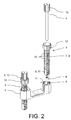
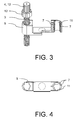
- Fig. 1 is a device for releasably securing a conductor 1 to a current transformer housing 2 with a holding element 3 and / or with a fastener 4 can be seen.
- the holding element 3 is guided through a detachable fastened to the current transformer housing 2 receiving element 5.
- the receiving element 5 is latched by means of a Verrastungsstoffs, not shown, with the current transformer housing 2.
- the receiving element 5 can be pressed against the current transformer housing 2 so that no further fastening means for securing the receiving element 5 to the current transformer housing 2 is necessary even in the attached state of the conductor 1 to the current transformer housing 2 of the support member 3 and the fastener 4.
- the fastening element 4 embodied as a screw is guided through the holding element 3 in such a way that the screw 4 can be rotated about its longitudinal axis for fastening the current conductor 1 to the current transformer housing 2 in a thread 6 designed as a nut.
- the holding element 3 is rotatable in the receiving element 5 about its longitudinal axis in such a way that the Retaining element 3 in a first rotational position along its longitudinal axis translationally for fastening or releasing of the conductor 1 is displaceable and the holding member 3 in a second rotational position along its longitudinal axis is translationally immovable.
- the receiving element 5 and the holding element 3 each have a nutfederartige surface 7, which engage in the second rotational position with each other such that the holding element 3 relative to the receiving element 5 is translationally immovable.
- this has the holding element 3 along its longitudinal axis extending outer surface on a second region 8, which, respectively, as shown Fig. 2 can be seen, a quarter of the outer periphery of the surface on the "front” and “back” of the support member 3 covered.
- a first region 9 which also has a groove-like surface 7, wherein in this first region 9, the grooves are designed as openings 10.
- this first area 9 of the holding element 3 in the receiving element 5 is aligned in the first rotational position corresponding to a flat surface 11 of the receiving element 5, the holding element 3 in this first rotational position along its longitudinal axis translationally in the receiving element 5 for fastening or releasing be moved from the conductor 1.
- the holding element 3 and the fastening element 4 each have a head 12, thus, for example, the screw an over-molded head 12, on.
- the holding element 3 is displaced translationally in the direction of the conductor 1 in the receiving element 5 in the first rotational position in which the flat surfaces 11 of the holding element 3 and the receiving element 5 correspond to one another , As soon as the holding element 3 touches the current conductor 1 or is aligned as close as possible to the surface of the current conductor 1, the holding element 3 is rotated in its second rotational position rotationally with respect to the receiving element 5. In this second rotational position, the region-wise arranged nutfedergiann surfaces 7 of the holding element 3 and the receiving element 5 engage each other such that the holding element 3 is translationally immovable along its longitudinal axis.
Landscapes
- Engineering & Computer Science (AREA)
- Power Engineering (AREA)
- Microelectronics & Electronic Packaging (AREA)
- Manufacturing & Machinery (AREA)
- Transformers For Measuring Instruments (AREA)
Claims (10)
- Dispositif de fixation amovible d'un conducteur électrique (1) sur un boîtier de convertisseur de courant (2), avec le boîtier de convertisseur de courant (2), un élément de retenue (3) passant à travers le boîtier de convertisseur de courant (2) et un élément de fixation (4) passant à travers l'élément de retenue (3), dans lequel
l'élément de fixation (4) et/ou l'élément de retenue (3), dans un état de fixation du conducteur électrique (1) sur le dispositif, peut / peuvent être appliqué/s au moins partiellement à la surface du conducteur électrique (1), afin de fixer le conducteur électrique (1) au niveau d'un orifice de passage du boîtier de convertisseur de courant (2),
l'élément de fixation (4) peut être mis en rotation autour de son axe longitudinal pour la fixation, respectivement le détachement, du conducteur électrique (1), et
l'élément de retenue (3) pouvant être mis en rotation autour de son axe longitudinal de telle manière que l'élément de retenue (3) peut être coulissé par translation le long de son axe longitudinal dans une première position de rotation pour la fixation, respectivement, le détachement, du conducteur électrique (1), et l'élément de retenue (3) est maintenu en ne pouvant pas coulisser par translation le long de son axe longitudinal sur le boîtier de convertisseur de courant (2) dans une deuxième position de rotation. - Dispositif selon la revendication précédente, dans lequel le boîtier de convertisseur de courant (2) et l'élément de retenue (3) présentent une surface (7) les mettant en prise respectivement l'un avec l'autre dans une deuxième région (8) s'étendant dans l'axe longitudinal de l'élément de retenue (3), qui sont conçus avec une rainure et un ressort, et la deuxième région (8) correspond à la deuxième position de rotation.
- Dispositif selon l'une des revendications précédentes, dans lequel le boîtier de convertisseur de courant (2) et/ou l'élément de retenue (3) présentent respectivement une surface (11) essentiellement plane dans une première région (9) s'étendant dans l'axe longitudinal de l'élément de retenue (3) et la première région (9) correspond à la première position de rotation.
- Dispositif selon l'une des revendications précédentes, dans lequel l'élément de retenue (3) présente une surface (7) dans une première région (9) s'étendant dans l'axe longitudinal de l'élément de retenue (3), qui est conçue avec une rainure et un ressort, le diamètre extérieur de l'élément de retenue (3) est plus petit le long de son axe longitudinal dans la première région (9) que dans la deuxième région (8), et la première région (9) correspond à la première position de rotation.
- Dispositif selon la revendication 4 précédente, dans lequel la rainure de la surface est conçue sous la forme d'un orifice (10).
- Dispositif selon l'une des revendications précédentes, dans lequel l'élément de fixation (4) est conçu sous la forme d'une vis, l'élément de retenue (3) présente un filetage (6) et la vis pour la fixation, respectivement, le détachement, du conducteur électrique (1) peut être mise en rotation dans le filetage (6).
- Dispositif selon l'une des revendications précédentes, avec un élément de logement (5) disposé sur le boîtier de convertisseur de courant (2), dans lequel l'élément de retenue (3) passe à travers l'élément de logement (5) et l'élément de logement (5) est fixé de manière amovible sur le boitier de convertisseur de courant (2).
- Dispositif selon l'une des revendications précédentes, dans lequel l'élément de retenue (3) présente une section transversale essentiellement de type circulaire, et la première région (9) et la deuxième région (8) s'étendent chacune sur un arc circonférentiel de 90 ° ou de 180 °.
- Dispositif selon l'une des revendications précédentes, dans lequel l'élément de retenue (3) et/ou l'élément de fixation (4) présentent chaque fois une tête (12) avec une surface de saisie conçue sous la forme d'une surface moletée.
- Procédé de fixation d'un conducteur électrique (1) sur un boîtier de convertisseur de courant (2) avec un élément de retenue (3) et/ou avec un élément de fixation (4), avec le boitier de convertisseur de courant (2), l'élément de retenue (3) passant à travers le boitier de convertisseur de courant (2) et l'élément de fixation (4) passant à travers l'élément de retenue (3),
dans lequel
l'élément de fixation (4) et/ou l'élément de retenue (3), dans un état de fixation du conducteur électrique (1) sur le dispositif, sont appliqués au moins partiellement contre la surface du conducteur électrique (1), afin de fixer le conducteur électrique (1) au niveau d'un orifice de passage du boîtier de convertisseur de courant (2), et
l'élément de retenue (3) peut être mis en rotation autour de son axe longitudinal à partir d'une première position de rotation vers une deuxième position de rotation, avec les étapes :de coulissement par translation de l'élément de retenue (3) le long de son axe longitudinal vers le conducteur électrique (1) dans la première position de rotation,de rotation de l'élément de retenue (3) dans la deuxième position de rotation, où l'élément de retenue (3) dans la deuxième position de rotation, est maintenu en ne pouvant pas coulisser par translation le long de son axe longitudinal sur le boitier de convertisseur de courant (2), etde rotation de l'élément de fixation (4) autour de son axe longitudinal vers le conducteur électrique (1).
Applications Claiming Priority (3)
| Application Number | Priority Date | Filing Date | Title |
|---|---|---|---|
| DE201010038040 DE102010038040A1 (de) | 2010-10-07 | 2010-10-07 | Vorrichtung zur lösbaren Befestigung eines Stromleiters an einem Stromwandlergehäuse |
| DE201020008746 DE202010008746U1 (de) | 2010-10-07 | 2010-10-07 | Vorrichtung zur lösbaren Befestigung eines Stromleiters an einem Stromwandlergehäuse |
| PCT/EP2011/067610 WO2012045884A1 (fr) | 2010-10-07 | 2011-10-07 | Dispositif de fixation libérable d'un conducteur à un boîtier de transformateur de courant |
Publications (2)
| Publication Number | Publication Date |
|---|---|
| EP2625701A1 EP2625701A1 (fr) | 2013-08-14 |
| EP2625701B1 true EP2625701B1 (fr) | 2016-02-10 |
Family
ID=44925496
Family Applications (1)
| Application Number | Title | Priority Date | Filing Date |
|---|---|---|---|
| EP11781459.0A Not-in-force EP2625701B1 (fr) | 2010-10-07 | 2011-10-07 | Dispositif de fixation libérable d'un conducteur à un boîtier de transformateur de courant |
Country Status (9)
| Country | Link |
|---|---|
| US (1) | US9006577B2 (fr) |
| EP (1) | EP2625701B1 (fr) |
| JP (1) | JP5442913B2 (fr) |
| KR (1) | KR101444092B1 (fr) |
| BR (1) | BR112013007982A2 (fr) |
| CA (1) | CA2813119A1 (fr) |
| RU (1) | RU2550345C2 (fr) |
| SG (1) | SG189193A1 (fr) |
| WO (1) | WO2012045884A1 (fr) |
Families Citing this family (7)
| Publication number | Priority date | Publication date | Assignee | Title |
|---|---|---|---|---|
| US5033250A (en) * | 1990-08-10 | 1991-07-23 | Package Machinery Company | Gum stick wrapping machine |
| WO2013047411A1 (fr) * | 2011-09-29 | 2013-04-04 | 富士フイルム株式会社 | Nouveau dérivé de triazine et absorbeur d'ultraviolet |
| WO2013183011A2 (fr) * | 2012-06-07 | 2013-12-12 | Intal Tech Ltd. | Blocs de construction d'équipement électronique pour un montage sur bâti |
| DE102012109869B3 (de) * | 2012-10-16 | 2014-03-13 | Phoenix Contact Gmbh & Co. Kg | Montageanordnung mit einem Stromwandler und Messanordnung |
| RU2622885C1 (ru) * | 2016-03-10 | 2017-06-21 | Общество с ограниченной ответственностью "АСТЕР" | Измерительный трансформатор тока |
| JP7492476B2 (ja) * | 2021-03-17 | 2024-05-29 | 大崎電気工業株式会社 | 変流器 |
| LU505822B1 (de) * | 2023-12-18 | 2025-06-19 | Phoenix Contact Gmbh & Co | Technik zum Spannungsabgriff für einen Stromwandler |
Family Cites Families (16)
| Publication number | Priority date | Publication date | Assignee | Title |
|---|---|---|---|---|
| FR2130753A5 (fr) | 1970-11-25 | 1972-11-10 | Sadtem | |
| JPS5933223U (ja) * | 1982-08-26 | 1984-03-01 | 三菱電機株式会社 | 母線直付け計器用変流器 |
| JPS6065413U (ja) * | 1983-10-14 | 1985-05-09 | 株式会社日立製作所 | フアスナ−構造 |
| JPH0768969B2 (ja) * | 1986-11-19 | 1995-07-26 | 日本ドライブイツト株式会社 | 締結具 |
| JPH01104710U (fr) * | 1988-01-05 | 1989-07-14 | ||
| JPH0272602U (fr) * | 1988-11-21 | 1990-06-04 | ||
| US5177325A (en) * | 1989-12-20 | 1993-01-05 | A. J. Giammanco & Associates, Inc. | Housing for electric transformer |
| JPH07127652A (ja) * | 1993-10-30 | 1995-05-16 | Shibuya Seisakusho:Kk | ねじ軸継手 |
| US5783775A (en) * | 1995-06-28 | 1998-07-21 | Cooper Industries, Inc. | Transformer door with corrosion resistant bottom strip |
| DE19733852A1 (de) * | 1997-08-05 | 1999-02-11 | Broeder Marie Luise | Schienenstromwandler mit formschlüssiger Primärschienenklemme |
| DE19833150C1 (de) | 1998-07-23 | 1999-10-14 | Moeller Gmbh | Anschlußklemme |
| JP2000048874A (ja) * | 1998-07-30 | 2000-02-18 | Osada:Kk | 端子台 |
| US6395979B1 (en) * | 2000-12-15 | 2002-05-28 | William English | Door bell junction box |
| US6683249B1 (en) * | 2002-08-05 | 2004-01-27 | Paula A. Leppin | Transformer assembly and transformer cover |
| JP2007288337A (ja) * | 2006-04-13 | 2007-11-01 | Mitsubishi Electric Corp | 誘導結合装置 |
| DE102009059007B4 (de) | 2009-12-17 | 2015-04-09 | Phoenix Contact Gmbh & Co. Kg | Vorrichtung zur lösbaren Befestigung eines Stromleiters an einem Stromwandlergehäuse |
-
2011
- 2011-10-07 US US13/877,959 patent/US9006577B2/en active Active
- 2011-10-07 WO PCT/EP2011/067610 patent/WO2012045884A1/fr not_active Ceased
- 2011-10-07 RU RU2013118461/07A patent/RU2550345C2/ru not_active IP Right Cessation
- 2011-10-07 SG SG2013024047A patent/SG189193A1/en unknown
- 2011-10-07 BR BR112013007982A patent/BR112013007982A2/pt not_active IP Right Cessation
- 2011-10-07 CA CA 2813119 patent/CA2813119A1/fr not_active Abandoned
- 2011-10-07 JP JP2013532227A patent/JP5442913B2/ja not_active Expired - Fee Related
- 2011-10-07 KR KR1020137011768A patent/KR101444092B1/ko not_active Expired - Fee Related
- 2011-10-07 EP EP11781459.0A patent/EP2625701B1/fr not_active Not-in-force
Also Published As
| Publication number | Publication date |
|---|---|
| KR101444092B1 (ko) | 2014-09-26 |
| US20130292151A1 (en) | 2013-11-07 |
| WO2012045884A1 (fr) | 2012-04-12 |
| JP2013545281A (ja) | 2013-12-19 |
| US9006577B2 (en) | 2015-04-14 |
| SG189193A1 (en) | 2013-05-31 |
| RU2550345C2 (ru) | 2015-05-10 |
| EP2625701A1 (fr) | 2013-08-14 |
| RU2013118461A (ru) | 2014-10-27 |
| CN103155061A (zh) | 2013-06-12 |
| JP5442913B2 (ja) | 2014-03-19 |
| BR112013007982A2 (pt) | 2016-06-14 |
| KR20130106403A (ko) | 2013-09-27 |
| CA2813119A1 (fr) | 2012-04-12 |
Similar Documents
| Publication | Publication Date | Title |
|---|---|---|
| EP2625701B1 (fr) | Dispositif de fixation libérable d'un conducteur à un boîtier de transformateur de courant | |
| DE102009059007B4 (de) | Vorrichtung zur lösbaren Befestigung eines Stromleiters an einem Stromwandlergehäuse | |
| EP2625700B1 (fr) | Dispositif pour fixer de manière amovible un conducteur de courant à un boîtier de transformateur de courant | |
| DE102011005598A1 (de) | Befestigungsvorrichtung zur Anordnung an einer Montageschiene | |
| EP3132146B1 (fr) | Dispositif de fixation | |
| EP3069408B1 (fr) | Moyens de fixation et le positionnement des une antenne sur une surface | |
| EP3838669B1 (fr) | Barre de verrouillage à installer dans un espace de chargement d'un véhicule | |
| DE102010038042B4 (de) | Montageanordnung zur lösbaren Befestigung eines Stromleiters an einem Stromwandlergehäuse | |
| DE102009059012B4 (de) | Vorrichtung zur lösbaren Befestigung eines Stromleiters an einem Stromwandlergehäuse | |
| DE19913022A1 (de) | Korbspule für Draht, insbesondere für Schweißdraht | |
| DE19946890A1 (de) | Halter für Kopfschrauben | |
| EP3133305A1 (fr) | Écrou cage | |
| DE102010038040A1 (de) | Vorrichtung zur lösbaren Befestigung eines Stromleiters an einem Stromwandlergehäuse | |
| DE202010008746U1 (de) | Vorrichtung zur lösbaren Befestigung eines Stromleiters an einem Stromwandlergehäuse | |
| EP2513920B1 (fr) | Dispositif de fixation amovible d'un conducteur électrique à un boîtier de convertisseur de courant | |
| AT405000B (de) | Feldabstandhalter für hochspannungs-freileitungen mit bündelleitern | |
| EP2578891B1 (fr) | Adapteur | |
| DE102018100999A1 (de) | Vorrichtung zum positionsgerechten Befestigen einer Antennenanordnung | |
| EP3240104B1 (fr) | Dispositif de fixation en position correcte d'un agencement d'antenne | |
| EP4310349B1 (fr) | Système de boulon de verrouillage comprenant une pluralité de boulons de verrouillage actionnés par des câbles bowden et une poignée commune | |
| EP3731247A1 (fr) | Ensemble pour un dispositif de passage permettant de connecter électriquement une installation de transformateur | |
| DE102017107534A1 (de) | Vorrichtung zum positionsgerechten Befestigen einer Antennenanordnung | |
| DE202024106621U1 (de) | Klemmvorrichtung | |
| DE102012220437A1 (de) | Seilklemmeinrichtung | |
| WO2013001003A1 (fr) | Système de liaison d'une connexion par fiche électrique |
Legal Events
| Date | Code | Title | Description |
|---|---|---|---|
| PUAI | Public reference made under article 153(3) epc to a published international application that has entered the european phase |
Free format text: ORIGINAL CODE: 0009012 |
|
| 17P | Request for examination filed |
Effective date: 20130403 |
|
| AK | Designated contracting states |
Kind code of ref document: A1 Designated state(s): AL AT BE BG CH CY CZ DE DK EE ES FI FR GB GR HR HU IE IS IT LI LT LU LV MC MK MT NL NO PL PT RO RS SE SI SK SM TR |
|
| DAX | Request for extension of the european patent (deleted) | ||
| RIN1 | Information on inventor provided before grant (corrected) |
Inventor name: THOERNER, CARSTEN Inventor name: DAT-MINH, TRINH Inventor name: LEIFER, CHRISTOPH |
|
| RIC1 | Information provided on ipc code assigned before grant |
Ipc: H01F 38/30 20060101AFI20150818BHEP Ipc: H05K 5/02 20060101ALI20150818BHEP Ipc: H01R 4/46 20060101ALI20150818BHEP Ipc: H05K 13/04 20060101ALI20150818BHEP |
|
| GRAP | Despatch of communication of intention to grant a patent |
Free format text: ORIGINAL CODE: EPIDOSNIGR1 |
|
| INTG | Intention to grant announced |
Effective date: 20151016 |
|
| GRAS | Grant fee paid |
Free format text: ORIGINAL CODE: EPIDOSNIGR3 |
|
| GRAA | (expected) grant |
Free format text: ORIGINAL CODE: 0009210 |
|
| AK | Designated contracting states |
Kind code of ref document: B1 Designated state(s): AL AT BE BG CH CY CZ DE DK EE ES FI FR GB GR HR HU IE IS IT LI LT LU LV MC MK MT NL NO PL PT RO RS SE SI SK SM TR |
|
| REG | Reference to a national code |
Ref country code: GB Ref legal event code: FG4D Free format text: NOT ENGLISH |
|
| REG | Reference to a national code |
Ref country code: AT Ref legal event code: REF Ref document number: 775010 Country of ref document: AT Kind code of ref document: T Effective date: 20160215 Ref country code: CH Ref legal event code: EP |
|
| REG | Reference to a national code |
Ref country code: IE Ref legal event code: FG4D Free format text: LANGUAGE OF EP DOCUMENT: GERMAN |
|
| REG | Reference to a national code |
Ref country code: DE Ref legal event code: R096 Ref document number: 502011008879 Country of ref document: DE |
|
| REG | Reference to a national code |
Ref country code: LT Ref legal event code: MG4D |
|
| REG | Reference to a national code |
Ref country code: NL Ref legal event code: MP Effective date: 20160210 |
|
| PG25 | Lapsed in a contracting state [announced via postgrant information from national office to epo] |
Ref country code: GR Free format text: LAPSE BECAUSE OF FAILURE TO SUBMIT A TRANSLATION OF THE DESCRIPTION OR TO PAY THE FEE WITHIN THE PRESCRIBED TIME-LIMIT Effective date: 20160511 Ref country code: HR Free format text: LAPSE BECAUSE OF FAILURE TO SUBMIT A TRANSLATION OF THE DESCRIPTION OR TO PAY THE FEE WITHIN THE PRESCRIBED TIME-LIMIT Effective date: 20160210 Ref country code: ES Free format text: LAPSE BECAUSE OF FAILURE TO SUBMIT A TRANSLATION OF THE DESCRIPTION OR TO PAY THE FEE WITHIN THE PRESCRIBED TIME-LIMIT Effective date: 20160210 Ref country code: FI Free format text: LAPSE BECAUSE OF FAILURE TO SUBMIT A TRANSLATION OF THE DESCRIPTION OR TO PAY THE FEE WITHIN THE PRESCRIBED TIME-LIMIT Effective date: 20160210 Ref country code: NO Free format text: LAPSE BECAUSE OF FAILURE TO SUBMIT A TRANSLATION OF THE DESCRIPTION OR TO PAY THE FEE WITHIN THE PRESCRIBED TIME-LIMIT Effective date: 20160510 Ref country code: IT Free format text: LAPSE BECAUSE OF FAILURE TO SUBMIT A TRANSLATION OF THE DESCRIPTION OR TO PAY THE FEE WITHIN THE PRESCRIBED TIME-LIMIT Effective date: 20160210 |
|
| PG25 | Lapsed in a contracting state [announced via postgrant information from national office to epo] |
Ref country code: SE Free format text: LAPSE BECAUSE OF FAILURE TO SUBMIT A TRANSLATION OF THE DESCRIPTION OR TO PAY THE FEE WITHIN THE PRESCRIBED TIME-LIMIT Effective date: 20160210 Ref country code: PT Free format text: LAPSE BECAUSE OF FAILURE TO SUBMIT A TRANSLATION OF THE DESCRIPTION OR TO PAY THE FEE WITHIN THE PRESCRIBED TIME-LIMIT Effective date: 20160613 Ref country code: NL Free format text: LAPSE BECAUSE OF FAILURE TO SUBMIT A TRANSLATION OF THE DESCRIPTION OR TO PAY THE FEE WITHIN THE PRESCRIBED TIME-LIMIT Effective date: 20160210 Ref country code: IS Free format text: LAPSE BECAUSE OF FAILURE TO SUBMIT A TRANSLATION OF THE DESCRIPTION OR TO PAY THE FEE WITHIN THE PRESCRIBED TIME-LIMIT Effective date: 20160610 Ref country code: LT Free format text: LAPSE BECAUSE OF FAILURE TO SUBMIT A TRANSLATION OF THE DESCRIPTION OR TO PAY THE FEE WITHIN THE PRESCRIBED TIME-LIMIT Effective date: 20160210 Ref country code: PL Free format text: LAPSE BECAUSE OF FAILURE TO SUBMIT A TRANSLATION OF THE DESCRIPTION OR TO PAY THE FEE WITHIN THE PRESCRIBED TIME-LIMIT Effective date: 20160210 Ref country code: RS Free format text: LAPSE BECAUSE OF FAILURE TO SUBMIT A TRANSLATION OF THE DESCRIPTION OR TO PAY THE FEE WITHIN THE PRESCRIBED TIME-LIMIT Effective date: 20160210 Ref country code: LV Free format text: LAPSE BECAUSE OF FAILURE TO SUBMIT A TRANSLATION OF THE DESCRIPTION OR TO PAY THE FEE WITHIN THE PRESCRIBED TIME-LIMIT Effective date: 20160210 |
|
| PG25 | Lapsed in a contracting state [announced via postgrant information from national office to epo] |
Ref country code: EE Free format text: LAPSE BECAUSE OF FAILURE TO SUBMIT A TRANSLATION OF THE DESCRIPTION OR TO PAY THE FEE WITHIN THE PRESCRIBED TIME-LIMIT Effective date: 20160210 Ref country code: DK Free format text: LAPSE BECAUSE OF FAILURE TO SUBMIT A TRANSLATION OF THE DESCRIPTION OR TO PAY THE FEE WITHIN THE PRESCRIBED TIME-LIMIT Effective date: 20160210 |
|
| REG | Reference to a national code |
Ref country code: DE Ref legal event code: R097 Ref document number: 502011008879 Country of ref document: DE |
|
| PG25 | Lapsed in a contracting state [announced via postgrant information from national office to epo] |
Ref country code: SK Free format text: LAPSE BECAUSE OF FAILURE TO SUBMIT A TRANSLATION OF THE DESCRIPTION OR TO PAY THE FEE WITHIN THE PRESCRIBED TIME-LIMIT Effective date: 20160210 Ref country code: RO Free format text: LAPSE BECAUSE OF FAILURE TO SUBMIT A TRANSLATION OF THE DESCRIPTION OR TO PAY THE FEE WITHIN THE PRESCRIBED TIME-LIMIT Effective date: 20160210 Ref country code: CZ Free format text: LAPSE BECAUSE OF FAILURE TO SUBMIT A TRANSLATION OF THE DESCRIPTION OR TO PAY THE FEE WITHIN THE PRESCRIBED TIME-LIMIT Effective date: 20160210 Ref country code: SM Free format text: LAPSE BECAUSE OF FAILURE TO SUBMIT A TRANSLATION OF THE DESCRIPTION OR TO PAY THE FEE WITHIN THE PRESCRIBED TIME-LIMIT Effective date: 20160210 |
|
| PLBE | No opposition filed within time limit |
Free format text: ORIGINAL CODE: 0009261 |
|
| STAA | Information on the status of an ep patent application or granted ep patent |
Free format text: STATUS: NO OPPOSITION FILED WITHIN TIME LIMIT |
|
| 26N | No opposition filed |
Effective date: 20161111 |
|
| PG25 | Lapsed in a contracting state [announced via postgrant information from national office to epo] |
Ref country code: BG Free format text: LAPSE BECAUSE OF FAILURE TO SUBMIT A TRANSLATION OF THE DESCRIPTION OR TO PAY THE FEE WITHIN THE PRESCRIBED TIME-LIMIT Effective date: 20160510 Ref country code: BE Free format text: LAPSE BECAUSE OF NON-PAYMENT OF DUE FEES Effective date: 20161031 Ref country code: SI Free format text: LAPSE BECAUSE OF FAILURE TO SUBMIT A TRANSLATION OF THE DESCRIPTION OR TO PAY THE FEE WITHIN THE PRESCRIBED TIME-LIMIT Effective date: 20160210 |
|
| REG | Reference to a national code |
Ref country code: CH Ref legal event code: PL |
|
| GBPC | Gb: european patent ceased through non-payment of renewal fee |
Effective date: 20161007 |
|
| REG | Reference to a national code |
Ref country code: IE Ref legal event code: MM4A |
|
| REG | Reference to a national code |
Ref country code: FR Ref legal event code: ST Effective date: 20170630 |
|
| PG25 | Lapsed in a contracting state [announced via postgrant information from national office to epo] |
Ref country code: CH Free format text: LAPSE BECAUSE OF NON-PAYMENT OF DUE FEES Effective date: 20161031 Ref country code: LI Free format text: LAPSE BECAUSE OF NON-PAYMENT OF DUE FEES Effective date: 20161031 Ref country code: FR Free format text: LAPSE BECAUSE OF NON-PAYMENT OF DUE FEES Effective date: 20161102 Ref country code: GB Free format text: LAPSE BECAUSE OF NON-PAYMENT OF DUE FEES Effective date: 20161007 |
|
| PG25 | Lapsed in a contracting state [announced via postgrant information from national office to epo] |
Ref country code: LU Free format text: LAPSE BECAUSE OF NON-PAYMENT OF DUE FEES Effective date: 20161007 |
|
| PG25 | Lapsed in a contracting state [announced via postgrant information from national office to epo] |
Ref country code: IE Free format text: LAPSE BECAUSE OF NON-PAYMENT OF DUE FEES Effective date: 20161007 |
|
| REG | Reference to a national code |
Ref country code: BE Ref legal event code: MM Effective date: 20161031 |
|
| REG | Reference to a national code |
Ref country code: AT Ref legal event code: MM01 Ref document number: 775010 Country of ref document: AT Kind code of ref document: T Effective date: 20161007 |
|
| PG25 | Lapsed in a contracting state [announced via postgrant information from national office to epo] |
Ref country code: AT Free format text: LAPSE BECAUSE OF NON-PAYMENT OF DUE FEES Effective date: 20161007 |
|
| PG25 | Lapsed in a contracting state [announced via postgrant information from national office to epo] |
Ref country code: CY Free format text: LAPSE BECAUSE OF FAILURE TO SUBMIT A TRANSLATION OF THE DESCRIPTION OR TO PAY THE FEE WITHIN THE PRESCRIBED TIME-LIMIT Effective date: 20160210 Ref country code: HU Free format text: LAPSE BECAUSE OF FAILURE TO SUBMIT A TRANSLATION OF THE DESCRIPTION OR TO PAY THE FEE WITHIN THE PRESCRIBED TIME-LIMIT; INVALID AB INITIO Effective date: 20111007 |
|
| PG25 | Lapsed in a contracting state [announced via postgrant information from national office to epo] |
Ref country code: MT Free format text: LAPSE BECAUSE OF FAILURE TO SUBMIT A TRANSLATION OF THE DESCRIPTION OR TO PAY THE FEE WITHIN THE PRESCRIBED TIME-LIMIT Effective date: 20160210 Ref country code: MC Free format text: LAPSE BECAUSE OF FAILURE TO SUBMIT A TRANSLATION OF THE DESCRIPTION OR TO PAY THE FEE WITHIN THE PRESCRIBED TIME-LIMIT Effective date: 20160210 Ref country code: MK Free format text: LAPSE BECAUSE OF FAILURE TO SUBMIT A TRANSLATION OF THE DESCRIPTION OR TO PAY THE FEE WITHIN THE PRESCRIBED TIME-LIMIT Effective date: 20160210 |
|
| PG25 | Lapsed in a contracting state [announced via postgrant information from national office to epo] |
Ref country code: AL Free format text: LAPSE BECAUSE OF FAILURE TO SUBMIT A TRANSLATION OF THE DESCRIPTION OR TO PAY THE FEE WITHIN THE PRESCRIBED TIME-LIMIT Effective date: 20160210 Ref country code: TR Free format text: LAPSE BECAUSE OF FAILURE TO SUBMIT A TRANSLATION OF THE DESCRIPTION OR TO PAY THE FEE WITHIN THE PRESCRIBED TIME-LIMIT Effective date: 20160210 |
|
| P01 | Opt-out of the competence of the unified patent court (upc) registered |
Effective date: 20230424 |
|
| PGFP | Annual fee paid to national office [announced via postgrant information from national office to epo] |
Ref country code: DE Payment date: 20231227 Year of fee payment: 13 |
|
| REG | Reference to a national code |
Ref country code: DE Ref legal event code: R119 Ref document number: 502011008879 Country of ref document: DE |
|
| PG25 | Lapsed in a contracting state [announced via postgrant information from national office to epo] |
Ref country code: DE Free format text: LAPSE BECAUSE OF NON-PAYMENT OF DUE FEES Effective date: 20250501 |