EP3240104B1 - Dispositif de fixation en position correcte d'un agencement d'antenne - Google Patents
Dispositif de fixation en position correcte d'un agencement d'antenne Download PDFInfo
- Publication number
- EP3240104B1 EP3240104B1 EP17168712.2A EP17168712A EP3240104B1 EP 3240104 B1 EP3240104 B1 EP 3240104B1 EP 17168712 A EP17168712 A EP 17168712A EP 3240104 B1 EP3240104 B1 EP 3240104B1
- Authority
- EP
- European Patent Office
- Prior art keywords
- recess
- clamping plate
- antenna
- antenna arrangement
- area
- Prior art date
- Legal status (The legal status is an assumption and is not a legal conclusion. Google has not performed a legal analysis and makes no representation as to the accuracy of the status listed.)
- Active
Links
Images



Classifications
-
- H—ELECTRICITY
- H01—ELECTRIC ELEMENTS
- H01Q—ANTENNAS, i.e. RADIO AERIALS
- H01Q1/00—Details of, or arrangements associated with, antennas
- H01Q1/27—Adaptation for use in or on movable bodies
- H01Q1/32—Adaptation for use in or on road or rail vehicles
- H01Q1/325—Adaptation for use in or on road or rail vehicles characterised by the location of the antenna on the vehicle
- H01Q1/3275—Adaptation for use in or on road or rail vehicles characterised by the location of the antenna on the vehicle mounted on a horizontal surface of the vehicle, e.g. on roof, hood, trunk
-
- H—ELECTRICITY
- H01—ELECTRIC ELEMENTS
- H01Q—ANTENNAS, i.e. RADIO AERIALS
- H01Q1/00—Details of, or arrangements associated with, antennas
- H01Q1/12—Supports; Mounting means
- H01Q1/1207—Supports; Mounting means for fastening a rigid aerial element
- H01Q1/1214—Supports; Mounting means for fastening a rigid aerial element through a wall
Definitions
- the invention relates to a device for correctly positioning an antenna arrangement on a surface which has a recess for antenna connection means, designed as plugs or sockets, the antenna arrangement having a base plate from which connecting means to the recess extend, which include a clamping plate secured against loss and comprise a screw or a screw bolt such that the clamping plate can be moved and braced in the direction of the base plate by means of a screw or screw bolt, according to the preamble of claim 1.
- a roof antenna which has a base plate for receiving antenna elements.
- the antenna elements are covered by an antenna hood that can be connected to the base plate.
- the previously known roof antenna should be able to be mounted by means of a screw connection on a fastening surface having a cutout, in particular a roof cutout, in particular a vehicle roof.
- the connecting means are designed as a clamping part that can be moved axially and radially between the base plate of the roof antenna and the fastening surface.
- the actual fastening is accordingly carried out by means of bracing, preferably by screwing.
- the fastening process is implemented via an initially axial and then radial movement of the clamping part. By turning the screw, the distance between the clamping plate and the base plate can be changed, resulting in the desired fastening and clamping of corresponding sections of the roof skin of the vehicle body.
- the known clamping part has an outer contour which makes it possible to pass it through a corresponding roof cutout in the mounting surface when the roof antenna is placed and then by rotating or moving the To bring the clamping part into engagement by a defined amount of this under the fastening surface, so that the clamping part cannot be removed from the roof cutout again against the direction of insertion.
- triangular, oval, elliptical or other polygonal or wedge-shaped outer contours of the clamping part should be particularly suitable.
- the first axial and then radial movement of the clamping part which is necessary in the prior art, requires an exact handling rule, which is disadvantageous in the case of basically quick and rapid assembly.
- a radial movement, in particular a rotation of a roof antenna configured in this way on a vehicle body is associated with the risk of damage to the body surface, in particular a layer of paint that has already been applied there.
- the task is to carry out the fastening process with the aid of a simple, quasi-intuitive movement routine, so that the assembly effort is reduced and this results in time and cost savings.
- the width of the recess is according to DE 20 2013 010 506 U1 at least in sections essentially the same as the width of the clamping plate for fastening the antenna.
- the length of the recess is smaller than the length of the clamping plate such that the connecting means, ie the clamping plate and the screw or the screw bolt, can be plunged into the recess in the shape of an arc of a circle and then braced.
- the mentioned arc-shaped immersion with the clamping plate first in the recess with subsequent moving into the recess as well as moving against the immersion direction in the sense of pivoting back can be done completely without contact with respect to the surface of a body in which the recess is located.
- connection means for the antenna must be passed through the clamping plate.
- the clamping plate is designed to virtually cover the space for the connection means.
- the object of the invention to provide a further developed device for correctly positioning an antenna arrangement on a surface which has a recess for antenna connection elements, designed as plugs or sockets and / or cables, on the one hand again an intuitive, quick, safe and simple implementation of the fastening process can be realized and at the same time the largest possible area is provided for the arrangement of the plugs, sockets or cables required for the antenna connection, and the clamping plate can safely absorb the forces required to fix the antenna for wiring even with a smaller clamping surface.
- antenna connection means are preferably designed as plugs or sockets, in particular as so-called FAKRA connectors, or connection cables.
- the antenna arrangement has a base plate from which connecting means extend in the direction of the recess.
- These connecting means comprise a clamping plate secured against loss and a screw or a screw bolt or similar means such that the clamping plate can be moved and braced in the direction of the base plate by means of a screw or screw bolt. This bracing causes the antenna arrangement to be fixed on the aforementioned vehicle roof or the like surface.
- the antenna has an antenna housing which is preferably designed in the form of a so-called shark fin or a similar flow-favorable design.
- the antenna housing and the entire antenna arrangement usually have a longitudinal axis which, in the assembled state, runs parallel to the longitudinal axis of the vehicle.
- the extension of the antenna arrangement or the housing and the base plate is implemented in such a way that the length dimensions are greater than the width dimensions, so that on the one hand the different antenna configurations for different frequency bands can be accommodated and combined in the housing and on the other hand the necessary aerodynamic shape to avoid wind noise is guaranteed.
- connection means as plugs, sockets or cables, e.g. B. FAKRA sockets are executed.
- connection means e.g. B. FAKRA sockets
- the connection means are freely accessible from behind or below in order to implement the necessary plug connections.
- This also applies to the power supply required for antennas that are usually actively implemented.
- the width of the recess to be made in the vehicle roof is smaller than the width of the clamping plate with the aid of which the antenna is fixed.
- the length of the recess is greater than the length of the clamping plate in such a way that the connecting means with the clamping plate can be laterally pivoted into the recess and shifted in the direction of the Longitudinal axis of the recess and the subsequent bracing can be realized.
- a group of plugs or sockets of the antenna connection means is located within the recess and is freely accessible.
- the plugs or sockets are in a first area of the base plate and the clamping plate is formed with screws or bolts in a second area of the base plate laterally spaced from the first plate area in such a way that the desired free access to the connection means is provided .
- connection means i.e. Sockets and / or plugs are available, which is owed to the fact and requirement that the number of antennas to be accommodated in the antenna housing with corresponding connections is subject to a constant increase due to a variety of radio communication solutions.
- the recess in the fastening surface in particular a vehicle body, is designed as an elongated hole or has an elongated hole shape, the recess merging into an adjoining opening for an anti-rotation device on the longitudinal axis of the elongated hole or the recess being a spaced one Associated opening for a twist protection known per se.
- projections extending in the direction of the recess are provided in the first area of the base plate for pre-locking and for protection against incorrect insertion, the projections being designed so that they approximate or approximate the contour of the hole pattern, in particular the slot-shaped recess, at least in partial sections Approximate the contour.
- the first area of the base plate has two spaced apart partial areas, the second area of the clamping plate being formed in the spacing space.
- the recess has a hole pattern in the form of an elongated hole with a waist.
- the clamping plate is positioned in the fastening state in the region of the waist.
- a second embodiment of the invention is based on a substantially circular recess which has a predetermined diameter.
- the clamping plate is longer than the diameter of the recess by a predetermined amount.
- the width of the clamping plate is smaller than the diameter of the recess by a predetermined amount.
- the resulting lateral gap between the clamping plate and the recess is used to accommodate connection cables or connection sockets.
- the cables with or without a plug are first passed through the hole pattern. Then the antenna arrangement with the clamping plate is angled in the longitudinal direction of the clamping plate and guided through the hole pattern on one side. The length of the clamping plate, which is greater than the diameter of the recess, determines the degree of angling to the lead through the hole pattern on one side.
- the antenna is moved slightly backwards against the direction of insertion. This continues until the antenna arrangement is seated and any anti-rotation device that may be present engages in a further recess in the vehicle roof. The clamping plate is then tightened by means of a screw or screw bolt in the direction of the base plate until the desired clamping and frictional connection is present.
- the clamping plate has recesses on its longitudinal sides, which at least partially receive and guide the connection cables. In this embodiment it is therefore not necessary to reduce the width of the clamping plate completely by the size of the connecting cable to be routed, since at least a partial cross-section of the corresponding cable is received by the respective recess in the clamping plate.
- the antenna arrangement shown in the exemplary embodiments is based on a fastening surface 1, in particular a vehicle roof.
- the fastening surface 1 has a recess 2 for antenna connection means 10.
- elements for protection against incorrect insertion and for pre-locking are designed in a manner known per se.
- a clamping plate 6 with a screw or screw bolt 7 is located in an area which is laterally removed from that of the antenna connection means 10.
- the clamping plate 6 can be moved and braced in the direction of the base plate 3, i.e. in the direction of the antenna housing, via the screw or the screw bolt 7 to fix the antenna arrangement in a clamping manner on the surface 1.
- the width B of the recess 2 is smaller than the width of the clamping plate 6.
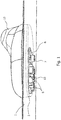
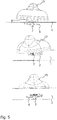
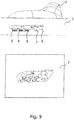
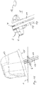
- the length L of the recess 2 is greater than the length of the clamping plate 6, in such a way that the connecting means with the clamping plate 6 can pivot into the recess 2 is, with the group of plugs or sockets 10 of the antenna connection means located within the recess 2 and freely accessible, as is in particular the Fig. 1 and the Fig. 9 demonstrate.
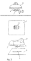
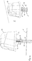
- the antenna arrangement is according to Fig. 2 positioned above the hole pattern, ie above the recess 2.
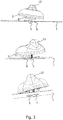
- the next step is according to Fig. 3 pivoting with a first end of the clamping plate dipping into the recess 2.
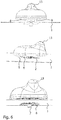
- FIG Fig. 4 the clamping plate pushed laterally through the recess 2 in the tilted or angled state.
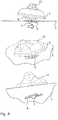
- the clamping plate is based on the Fig. 4 opposite side (see Fig. 5 ) through the recess, ie through the hole pattern.
- the clamping plate 2 which is larger than the recess with the corresponding hole pattern, is located completely below the surface 1.
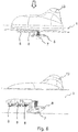
- the antenna arrangement is then shifted in the direction of the longitudinal axis of the recess until the end position is reached with a view of the opening 12 adjoining recess 2, which is more or less an extension of the recess.
- the screw or screw bolt 7 can now be actuated until the clamping plate 6 comes into contact with the underside of the surface 1, so that the desired surface pressure and thus the fastening of the antenna arrangement is set.
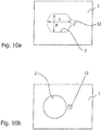
- FIG Figure 10a The basic embodiment of the recess 2 in the form of a hole pattern similar to a slot is shown in FIG Figure 10a ) shown.
- This shape of the hole pattern is preferably used in the original equipment or in the assembly of a corresponding antenna in accordance with the motor vehicle manufacture.
- the hole pattern according to Figure 10b ) can be used for retrofitting purposes.
- the circular recess provided in this case is easier to implement in the case of retrofitting by workshops or by laypeople. Possible disadvantages due to a somewhat longer period of time when pivoting in and finding the exact position with regard to the clamping plate and its location below the surface 1 can be accepted.
- the hole pattern according to Figure 10b is represented as a circular hole pattern 2.
- a distance from the circular hole pattern 2 is a smaller, here also circular recess 12 for receiving an anti-rotation nose which extends from the base plate of the antenna arrangement in the direction of the mounting surface.
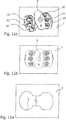
- the recess 2 according to Figure 11a ) from the basic structure also has the shape of an elongated hole, but with a waist 14 quasi in the central area.
- the first area of the base plate 3 of the antenna arrangement has two spaced apart partial areas, the second area being formed with a clamping plate 6 in the spacing space.
- the hole patterns for standard equipment or for retrofitting in the after-market business are the same in terms of dimensions.
- the entire antenna is swiveled in with a view to the features according to the invention as explained above. This is not possible when retrofitting an antenna.
- the clamping plate or nut and screw is dismantled and the antenna is placed on the recess and then screwed.
- all hole patterns can be used with a single antenna configuration.
- series assembly it should be noted that assembly without a pivoting movement is not possible.
- the antenna arrangement is usually mounted or swiveled in over the shortest side of the base plate to the fastening center point.
- the recess can in principle be kept small and the screw for fastening short, since it does not protrude too far into the passenger compartment for external installation or into the housing for internal installation.
- Another positive side effect is that the construction height of the housing can be reduced, which leads to a reduction in weight and material savings.
- An antenna arrangement 13 is to be mounted on a fastening surface 1, for example a vehicle roof.
- the antenna connection means 10 are designed here as cables, at the ends of which there are plugs or sockets (not shown).
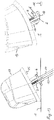
- Fig. 12 the cables are inserted through a circular recess 2 (see also Figure 10b )) guided.
- the antenna arrangement 13 is angled, the clamping plate 6 following the angling. In this way the clamping plate can be swiveled into the recess 2 ( Fig. 13 ).
- the longitudinal extent of the clamping plate 6 is greater than the diameter of the circular recess 2 by a defined amount.
- the width of the clamping plate 6 is therefore selected to be smaller than the diameter of the recess 2 for assembly in the recess 2 with a circular cross section.
- the clamping plate 6 can have recesses on its longitudinal sides where the antenna connection means 10 lie, e.g. B. recesses that are adapted to the cross-sectional area of the connection means 10 in question. This results in a further guidance and secure fixing of the connection means, so that a Damage to this in later operation, e.g. B. due to metal edges in the recess, are excluded.
- the base plate 3 of the antenna arrangement 13 comes to rest on the upper side of the fastening surface 1.
- a locking extension e.g. B. designed as a nose 15, extends from the base plate 3 in the direction of a locking opening 12, so that the desired anti-twist protection is given. If the position according to Fig. 16 is reached, the antenna arrangement 13 is then braced using the screw bolt 7.
Landscapes
- Engineering & Computer Science (AREA)
- Remote Sensing (AREA)
- Support Of Aerials (AREA)
Claims (5)
- Agencement d'antenne pour la fixation en position correcte sur une surface (1) qui comprend une échancrure (2) pour des moyens de raccordement de l'agencement d'antenne, réalisés sous forme de prises mâles ou femelles (10), l'agencement d'antenne possédant une plaque de fond (3) à partir de laquelle des moyens de liaison s'étendent vers l'échancrure (2) qui comprennent une plaque de coincement (6) sécurisée à l'encontre d'une perte et une vis ou un boulon fileté (7) de telle sorte que la plaque de coincement (6) est susceptible d'être déplacée et d'être serrée par la vis ou par le boulon fileté (7) en direction de la plaque de fond (3), dans lequel
la largeur (B) de l'échancrure (2) est inférieure à la largeur de la plaque de coincement (6) et la longueur (L) de l'échancrure (2) est supérieure à la longueur de la plaque de coincement (6), afin de permettre une insertion pivotante des moyens de liaison avec la plaque de coincement (6) jusque dans l'échancrure (2), une translation en direction de l'axe longitudinal de l'échancrure (2) et ensuite un serrage,
une fois que la position finale de fixation en position correcte est atteinte, les prises mâles ou femelles (10) des moyens de raccordement d'antenne sont situées à l'intérieur de l'échancrure (2) et sont librement accessibles, caractérisé en ce que
les prises mâles ou femelles (10) sont formées dans une première zone de la plaque de fond (3) et la plaque de coincement (6) avec vis ou boulon fileté (7) est formée dans une deuxième zone de la plaque de fond (3), espacée latéralement de la première, de telle sorte qu'un accès libre aux moyens de raccordement est assuré, et en outre
l'échancrure (2) présente une forme de trou oblong, et sur l'axe longitudinal du trou oblong, l'échancrure (2) se transforme en une ouverture (12) adjacente pour une protection anti-rotation, ou bien une ouverture (12) espacée pour une protection anti-rotation est associée à l'échancrure (2). - Agencement d'antenne selon la revendication 1,
caractérisé en ce que dans la première zone de la plaque de fond (3), des prolongements (8) s'étendant en direction de l'échancrure (2) sont prévus pour le pré-encliquetage et pour la protection contre les fausses manœuvres, les prolongements (8) étant réalisés de telle sorte qu'ils s'approchent, au moins dans des sections partielles, du contour de la configuration de trous, en particulier de l'échancrure en forme de trou oblong ou qu'ils ressemblent à ce contour. - Agencement d'antenne selon l'une des revendications 1 ou 2,
caractérisé en ce que la première zone de la plaque de fond (3) comprend deux zones partielles écartées, la seconde zone ayant la plaque de coincement (6) étant réalisée dans l'espace d'écartement. - Agencement d'antenne selon la revendication 3,
caractérisé en ce que l'échancrure (2) présente une configuration de trou sous forme de trou oblong avec rétrécissement (14). - Agencement d'antenne selon la revendication 4,
caractérisé en ce que la plaque de coincement (6) est positionnée au niveau du rétrécissement, dans l'état de fixation.
Applications Claiming Priority (3)
| Application Number | Priority Date | Filing Date | Title |
|---|---|---|---|
| DE102016005238 | 2016-04-29 | ||
| DE102016121697 | 2016-11-11 | ||
| DE102017107534.8A DE102017107534A1 (de) | 2016-04-29 | 2017-04-07 | Vorrichtung zum positionsgerechten Befestigen einer Antennenanordnung |
Publications (2)
| Publication Number | Publication Date |
|---|---|
| EP3240104A1 EP3240104A1 (fr) | 2017-11-01 |
| EP3240104B1 true EP3240104B1 (fr) | 2020-09-30 |
Family
ID=58644951
Family Applications (1)
| Application Number | Title | Priority Date | Filing Date |
|---|---|---|---|
| EP17168712.2A Active EP3240104B1 (fr) | 2016-04-29 | 2017-04-28 | Dispositif de fixation en position correcte d'un agencement d'antenne |
Country Status (1)
| Country | Link |
|---|---|
| EP (1) | EP3240104B1 (fr) |
Families Citing this family (1)
| Publication number | Priority date | Publication date | Assignee | Title |
|---|---|---|---|---|
| DE102019211755B3 (de) * | 2019-08-06 | 2020-12-31 | Volkswagen Aktiengesellschaft | Befestigungssystem für eine modulare Antenne |
Family Cites Families (6)
| Publication number | Priority date | Publication date | Assignee | Title |
|---|---|---|---|---|
| US3138661A (en) * | 1963-02-06 | 1964-06-23 | Grashow Joseph | Automobile antenna mount structure |
| US4136986A (en) * | 1977-06-20 | 1979-01-30 | Quick-Mount Manufacturing Company, Inc. | Automobile antenna mount structure |
| DE102005044618B4 (de) | 2005-04-12 | 2022-06-30 | Hirschmann Car Communication Gmbh | Befestigung einer Dachantenne eines Fahrzeuges mit einem Klemmteil |
| SE532656C2 (sv) * | 2008-07-17 | 2010-03-09 | Smarteq Wireless Ab | En antennenhet |
| DE202013010506U1 (de) | 2013-11-11 | 2014-01-09 | Antennentechnik Abb Bad Blankenburg Gmbh | Vorrichtung zum positionsgerechten Befestigen einer Antennenanordnung an einer Fläche |
| SE539263C2 (en) * | 2015-10-08 | 2017-06-07 | Scania Cv Ab | Fastening device, primarily for installation of an antenna on a vehicle |
-
2017
- 2017-04-28 EP EP17168712.2A patent/EP3240104B1/fr active Active
Non-Patent Citations (1)
| Title |
|---|
| None * |
Also Published As
| Publication number | Publication date |
|---|---|
| EP3240104A1 (fr) | 2017-11-01 |
Similar Documents
| Publication | Publication Date | Title |
|---|---|---|
| EP1851830B1 (fr) | Systeme de liaison, notamment systeme de connexion electrique | |
| EP3164911B1 (fr) | Fiche de raccordement | |
| DE102017205533B4 (de) | Haltevorrichtung, Kraftfahrzeug | |
| EP3710711A1 (fr) | Dispositif de fixation et utilisation d'un dispositif de fixation | |
| EP3224907B1 (fr) | Connecteur pour films de circuit imprimé flexibles | |
| EP2625701B1 (fr) | Dispositif de fixation libérable d'un conducteur à un boîtier de transformateur de courant | |
| EP3069408B1 (fr) | Moyens de fixation et le positionnement des une antenne sur une surface | |
| WO2016165823A1 (fr) | Dispositif de fixation | |
| WO2015131875A1 (fr) | Élément de fixation pour un capteur de courant | |
| EP2019259B1 (fr) | Système de liaison pour rails de support d'éléments d'éclairage d'une bande de lumière | |
| EP3016215A1 (fr) | Dispositif de mise a la terre de rails | |
| DE102018100999A1 (de) | Vorrichtung zum positionsgerechten Befestigen einer Antennenanordnung | |
| EP3240104A1 (fr) | Dispositif de fixation en position correcte d'un agencement d'antenne | |
| DE2323612A1 (de) | Elektrisches verbindungsglied | |
| DE102017107534A1 (de) | Vorrichtung zum positionsgerechten Befestigen einer Antennenanordnung | |
| DE102023118145A1 (de) | Adapterklemme zum Anklemmen eines elektrischen Leiters an eine Sammelschiene und damit gebildete Anordnung | |
| EP3497002B1 (fr) | Cadre pour compensation le jeu autour le phare | |
| WO2015007562A1 (fr) | Agencement de pièces d'un volant de direction | |
| DE29505752U1 (de) | Vorrichtung zum Verbinden von Platten mittels Verschraubung | |
| DE29603747U1 (de) | Vorrichtung zur Masseverbindung von Flachbaugruppen an einer Gehäusewandung | |
| DE102007062956B3 (de) | Montagehilfe für das Montieren von wenigstens zwei Kabelschuhen | |
| WO2015193190A1 (fr) | Ensemble d'éclairage | |
| DE102019107419A1 (de) | Kabelbrücke | |
| EP3996221B1 (fr) | Dispositif de fixation de rail porteur, agencement et armoire de commande | |
| DE102005032092B4 (de) | Kondensatormodul |
Legal Events
| Date | Code | Title | Description |
|---|---|---|---|
| PUAI | Public reference made under article 153(3) epc to a published international application that has entered the european phase |
Free format text: ORIGINAL CODE: 0009012 |
|
| STAA | Information on the status of an ep patent application or granted ep patent |
Free format text: STATUS: THE APPLICATION HAS BEEN PUBLISHED |
|
| AK | Designated contracting states |
Kind code of ref document: A1 Designated state(s): AL AT BE BG CH CY CZ DE DK EE ES FI FR GB GR HR HU IE IS IT LI LT LU LV MC MK MT NL NO PL PT RO RS SE SI SK SM TR |
|
| AX | Request for extension of the european patent |
Extension state: BA ME |
|
| STAA | Information on the status of an ep patent application or granted ep patent |
Free format text: STATUS: REQUEST FOR EXAMINATION WAS MADE |
|
| 17P | Request for examination filed |
Effective date: 20180328 |
|
| RBV | Designated contracting states (corrected) |
Designated state(s): AL AT BE BG CH CY CZ DE DK EE ES FI FR GB GR HR HU IE IS IT LI LT LU LV MC MK MT NL NO PL PT RO RS SE SI SK SM TR |
|
| RAP1 | Party data changed (applicant data changed or rights of an application transferred) |
Owner name: ANTENNENTECHNIK BAD BLANKENBURG GMBH |
|
| GRAP | Despatch of communication of intention to grant a patent |
Free format text: ORIGINAL CODE: EPIDOSNIGR1 |
|
| STAA | Information on the status of an ep patent application or granted ep patent |
Free format text: STATUS: GRANT OF PATENT IS INTENDED |
|
| INTG | Intention to grant announced |
Effective date: 20200422 |
|
| GRAS | Grant fee paid |
Free format text: ORIGINAL CODE: EPIDOSNIGR3 |
|
| GRAA | (expected) grant |
Free format text: ORIGINAL CODE: 0009210 |
|
| STAA | Information on the status of an ep patent application or granted ep patent |
Free format text: STATUS: THE PATENT HAS BEEN GRANTED |
|
| AK | Designated contracting states |
Kind code of ref document: B1 Designated state(s): AL AT BE BG CH CY CZ DE DK EE ES FI FR GB GR HR HU IE IS IT LI LT LU LV MC MK MT NL NO PL PT RO RS SE SI SK SM TR |
|
| REG | Reference to a national code |
Ref country code: CH Ref legal event code: EP Ref country code: GB Ref legal event code: FG4D Free format text: NOT ENGLISH |
|
| REG | Reference to a national code |
Ref country code: DE Ref legal event code: R096 Ref document number: 502017007467 Country of ref document: DE Ref country code: AT Ref legal event code: REF Ref document number: 1319739 Country of ref document: AT Kind code of ref document: T Effective date: 20201015 |
|
| REG | Reference to a national code |
Ref country code: IE Ref legal event code: FG4D Free format text: LANGUAGE OF EP DOCUMENT: GERMAN |
|
| PG25 | Lapsed in a contracting state [announced via postgrant information from national office to epo] |
Ref country code: FI Free format text: LAPSE BECAUSE OF FAILURE TO SUBMIT A TRANSLATION OF THE DESCRIPTION OR TO PAY THE FEE WITHIN THE PRESCRIBED TIME-LIMIT Effective date: 20200930 Ref country code: NO Free format text: LAPSE BECAUSE OF FAILURE TO SUBMIT A TRANSLATION OF THE DESCRIPTION OR TO PAY THE FEE WITHIN THE PRESCRIBED TIME-LIMIT Effective date: 20201230 Ref country code: GR Free format text: LAPSE BECAUSE OF FAILURE TO SUBMIT A TRANSLATION OF THE DESCRIPTION OR TO PAY THE FEE WITHIN THE PRESCRIBED TIME-LIMIT Effective date: 20201231 Ref country code: HR Free format text: LAPSE BECAUSE OF FAILURE TO SUBMIT A TRANSLATION OF THE DESCRIPTION OR TO PAY THE FEE WITHIN THE PRESCRIBED TIME-LIMIT Effective date: 20200930 Ref country code: BG Free format text: LAPSE BECAUSE OF FAILURE TO SUBMIT A TRANSLATION OF THE DESCRIPTION OR TO PAY THE FEE WITHIN THE PRESCRIBED TIME-LIMIT Effective date: 20201230 |
|
| PG25 | Lapsed in a contracting state [announced via postgrant information from national office to epo] |
Ref country code: LV Free format text: LAPSE BECAUSE OF FAILURE TO SUBMIT A TRANSLATION OF THE DESCRIPTION OR TO PAY THE FEE WITHIN THE PRESCRIBED TIME-LIMIT Effective date: 20200930 Ref country code: RS Free format text: LAPSE BECAUSE OF FAILURE TO SUBMIT A TRANSLATION OF THE DESCRIPTION OR TO PAY THE FEE WITHIN THE PRESCRIBED TIME-LIMIT Effective date: 20200930 |
|
| REG | Reference to a national code |
Ref country code: LT Ref legal event code: MG4D |
|
| PG25 | Lapsed in a contracting state [announced via postgrant information from national office to epo] |
Ref country code: LT Free format text: LAPSE BECAUSE OF FAILURE TO SUBMIT A TRANSLATION OF THE DESCRIPTION OR TO PAY THE FEE WITHIN THE PRESCRIBED TIME-LIMIT Effective date: 20200930 Ref country code: CZ Free format text: LAPSE BECAUSE OF FAILURE TO SUBMIT A TRANSLATION OF THE DESCRIPTION OR TO PAY THE FEE WITHIN THE PRESCRIBED TIME-LIMIT Effective date: 20200930 Ref country code: RO Free format text: LAPSE BECAUSE OF FAILURE TO SUBMIT A TRANSLATION OF THE DESCRIPTION OR TO PAY THE FEE WITHIN THE PRESCRIBED TIME-LIMIT Effective date: 20200930 Ref country code: PT Free format text: LAPSE BECAUSE OF FAILURE TO SUBMIT A TRANSLATION OF THE DESCRIPTION OR TO PAY THE FEE WITHIN THE PRESCRIBED TIME-LIMIT Effective date: 20210201 Ref country code: EE Free format text: LAPSE BECAUSE OF FAILURE TO SUBMIT A TRANSLATION OF THE DESCRIPTION OR TO PAY THE FEE WITHIN THE PRESCRIBED TIME-LIMIT Effective date: 20200930 Ref country code: SM Free format text: LAPSE BECAUSE OF FAILURE TO SUBMIT A TRANSLATION OF THE DESCRIPTION OR TO PAY THE FEE WITHIN THE PRESCRIBED TIME-LIMIT Effective date: 20200930 |
|
| PG25 | Lapsed in a contracting state [announced via postgrant information from national office to epo] |
Ref country code: AL Free format text: LAPSE BECAUSE OF FAILURE TO SUBMIT A TRANSLATION OF THE DESCRIPTION OR TO PAY THE FEE WITHIN THE PRESCRIBED TIME-LIMIT Effective date: 20200930 Ref country code: ES Free format text: LAPSE BECAUSE OF FAILURE TO SUBMIT A TRANSLATION OF THE DESCRIPTION OR TO PAY THE FEE WITHIN THE PRESCRIBED TIME-LIMIT Effective date: 20200930 Ref country code: IS Free format text: LAPSE BECAUSE OF FAILURE TO SUBMIT A TRANSLATION OF THE DESCRIPTION OR TO PAY THE FEE WITHIN THE PRESCRIBED TIME-LIMIT Effective date: 20210130 Ref country code: PL Free format text: LAPSE BECAUSE OF FAILURE TO SUBMIT A TRANSLATION OF THE DESCRIPTION OR TO PAY THE FEE WITHIN THE PRESCRIBED TIME-LIMIT Effective date: 20200930 |
|
| PG25 | Lapsed in a contracting state [announced via postgrant information from national office to epo] |
Ref country code: SK Free format text: LAPSE BECAUSE OF FAILURE TO SUBMIT A TRANSLATION OF THE DESCRIPTION OR TO PAY THE FEE WITHIN THE PRESCRIBED TIME-LIMIT Effective date: 20200930 |
|
| REG | Reference to a national code |
Ref country code: DE Ref legal event code: R097 Ref document number: 502017007467 Country of ref document: DE |
|
| PLBE | No opposition filed within time limit |
Free format text: ORIGINAL CODE: 0009261 |
|
| STAA | Information on the status of an ep patent application or granted ep patent |
Free format text: STATUS: NO OPPOSITION FILED WITHIN TIME LIMIT |
|
| PG25 | Lapsed in a contracting state [announced via postgrant information from national office to epo] |
Ref country code: DK Free format text: LAPSE BECAUSE OF FAILURE TO SUBMIT A TRANSLATION OF THE DESCRIPTION OR TO PAY THE FEE WITHIN THE PRESCRIBED TIME-LIMIT Effective date: 20200930 |
|
| 26N | No opposition filed |
Effective date: 20210701 |
|
| REG | Reference to a national code |
Ref country code: NL Ref legal event code: FP |
|
| PG25 | Lapsed in a contracting state [announced via postgrant information from national office to epo] |
Ref country code: IT Free format text: LAPSE BECAUSE OF FAILURE TO SUBMIT A TRANSLATION OF THE DESCRIPTION OR TO PAY THE FEE WITHIN THE PRESCRIBED TIME-LIMIT Effective date: 20200930 |
|
| PG25 | Lapsed in a contracting state [announced via postgrant information from national office to epo] |
Ref country code: SI Free format text: LAPSE BECAUSE OF FAILURE TO SUBMIT A TRANSLATION OF THE DESCRIPTION OR TO PAY THE FEE WITHIN THE PRESCRIBED TIME-LIMIT Effective date: 20200930 Ref country code: MC Free format text: LAPSE BECAUSE OF FAILURE TO SUBMIT A TRANSLATION OF THE DESCRIPTION OR TO PAY THE FEE WITHIN THE PRESCRIBED TIME-LIMIT Effective date: 20200930 |
|
| PG25 | Lapsed in a contracting state [announced via postgrant information from national office to epo] |
Ref country code: LU Free format text: LAPSE BECAUSE OF NON-PAYMENT OF DUE FEES Effective date: 20210428 |
|
| PG25 | Lapsed in a contracting state [announced via postgrant information from national office to epo] |
Ref country code: CH Free format text: LAPSE BECAUSE OF NON-PAYMENT OF DUE FEES Effective date: 20210430 Ref country code: LI Free format text: LAPSE BECAUSE OF NON-PAYMENT OF DUE FEES Effective date: 20210430 |
|
| PG25 | Lapsed in a contracting state [announced via postgrant information from national office to epo] |
Ref country code: IE Free format text: LAPSE BECAUSE OF NON-PAYMENT OF DUE FEES Effective date: 20210428 |
|
| PG25 | Lapsed in a contracting state [announced via postgrant information from national office to epo] |
Ref country code: IS Free format text: LAPSE BECAUSE OF FAILURE TO SUBMIT A TRANSLATION OF THE DESCRIPTION OR TO PAY THE FEE WITHIN THE PRESCRIBED TIME-LIMIT Effective date: 20210130 |
|
| PG25 | Lapsed in a contracting state [announced via postgrant information from national office to epo] |
Ref country code: HU Free format text: LAPSE BECAUSE OF FAILURE TO SUBMIT A TRANSLATION OF THE DESCRIPTION OR TO PAY THE FEE WITHIN THE PRESCRIBED TIME-LIMIT; INVALID AB INITIO Effective date: 20170428 |
|
| REG | Reference to a national code |
Ref country code: AT Ref legal event code: MM01 Ref document number: 1319739 Country of ref document: AT Kind code of ref document: T Effective date: 20220428 |
|
| PG25 | Lapsed in a contracting state [announced via postgrant information from national office to epo] |
Ref country code: CY Free format text: LAPSE BECAUSE OF FAILURE TO SUBMIT A TRANSLATION OF THE DESCRIPTION OR TO PAY THE FEE WITHIN THE PRESCRIBED TIME-LIMIT Effective date: 20200930 |
|
| PG25 | Lapsed in a contracting state [announced via postgrant information from national office to epo] |
Ref country code: AT Free format text: LAPSE BECAUSE OF NON-PAYMENT OF DUE FEES Effective date: 20220428 |
|
| P01 | Opt-out of the competence of the unified patent court (upc) registered |
Effective date: 20230629 |
|
| REG | Reference to a national code |
Ref country code: DE Ref legal event code: R081 Ref document number: 502017007467 Country of ref document: DE Owner name: DESAY SV AUTOMOTIVE EUROPE GMBH, DE Free format text: FORMER OWNER: ANTENNENTECHNIK BAD BLANKENBURG GMBH, 99428 WEIMAR, DE |
|
| REG | Reference to a national code |
Ref country code: NL Ref legal event code: PD Owner name: DESAY SV AUTOMOTIVE EUROPE GMBH; DE Free format text: DETAILS ASSIGNMENT: CHANGE OF OWNER(S), MERGE; FORMER OWNER NAME: ANTENNENTECHNIK BAD BLANKENBURG GMBH Effective date: 20231106 |
|
| REG | Reference to a national code |
Ref country code: GB Ref legal event code: 732E Free format text: REGISTERED BETWEEN 20231116 AND 20231122 |
|
| REG | Reference to a national code |
Ref country code: BE Ref legal event code: PD Owner name: ANTEBB HOLDING GMBH; DE Free format text: DETAILS ASSIGNMENT: CHANGE OF OWNER(S), MERGE; FORMER OWNER NAME: ANTEBB HOLDING GMBH Effective date: 20231106 |
|
| PG25 | Lapsed in a contracting state [announced via postgrant information from national office to epo] |
Ref country code: MK Free format text: LAPSE BECAUSE OF FAILURE TO SUBMIT A TRANSLATION OF THE DESCRIPTION OR TO PAY THE FEE WITHIN THE PRESCRIBED TIME-LIMIT Effective date: 20200930 |
|
| PG25 | Lapsed in a contracting state [announced via postgrant information from national office to epo] |
Ref country code: TR Free format text: LAPSE BECAUSE OF FAILURE TO SUBMIT A TRANSLATION OF THE DESCRIPTION OR TO PAY THE FEE WITHIN THE PRESCRIBED TIME-LIMIT Effective date: 20200930 |
|
| PG25 | Lapsed in a contracting state [announced via postgrant information from national office to epo] |
Ref country code: MT Free format text: LAPSE BECAUSE OF FAILURE TO SUBMIT A TRANSLATION OF THE DESCRIPTION OR TO PAY THE FEE WITHIN THE PRESCRIBED TIME-LIMIT Effective date: 20200930 |
|
| PGFP | Annual fee paid to national office [announced via postgrant information from national office to epo] |
Ref country code: SE Payment date: 20250228 Year of fee payment: 9 |
|
| PGFP | Annual fee paid to national office [announced via postgrant information from national office to epo] |
Ref country code: NL Payment date: 20250424 Year of fee payment: 9 |
|
| PGFP | Annual fee paid to national office [announced via postgrant information from national office to epo] |
Ref country code: DE Payment date: 20250430 Year of fee payment: 9 |
|
| PGFP | Annual fee paid to national office [announced via postgrant information from national office to epo] |
Ref country code: GB Payment date: 20250422 Year of fee payment: 9 |
|
| PGFP | Annual fee paid to national office [announced via postgrant information from national office to epo] |
Ref country code: BE Payment date: 20250424 Year of fee payment: 9 |
|
| PGFP | Annual fee paid to national office [announced via postgrant information from national office to epo] |
Ref country code: FR Payment date: 20250424 Year of fee payment: 9 |