EP2626236B1 - Véhicule automobile doté d'un banc - Google Patents
Véhicule automobile doté d'un banc Download PDFInfo
- Publication number
- EP2626236B1 EP2626236B1 EP12154890.3A EP12154890A EP2626236B1 EP 2626236 B1 EP2626236 B1 EP 2626236B1 EP 12154890 A EP12154890 A EP 12154890A EP 2626236 B1 EP2626236 B1 EP 2626236B1
- Authority
- EP
- European Patent Office
- Prior art keywords
- backrest
- motor vehicle
- partition
- seat surface
- region
- Prior art date
- Legal status (The legal status is an assumption and is not a legal conclusion. Google has not performed a legal analysis and makes no representation as to the accuracy of the status listed.)
- Active
Links
Images

Classifications
-
- B—PERFORMING OPERATIONS; TRANSPORTING
- B60—VEHICLES IN GENERAL
- B60N—SEATS SPECIALLY ADAPTED FOR VEHICLES; VEHICLE PASSENGER ACCOMMODATION NOT OTHERWISE PROVIDED FOR
- B60N2/00—Seats specially adapted for vehicles; Arrangement or mounting of seats in vehicles
- B60N2/24—Seats specially adapted for vehicles; Arrangement or mounting of seats in vehicles for particular purposes or particular vehicles
- B60N2/32—Seats specially adapted for vehicles; Arrangement or mounting of seats in vehicles for particular purposes or particular vehicles convertible for other use
-
- B—PERFORMING OPERATIONS; TRANSPORTING
- B60—VEHICLES IN GENERAL
- B60N—SEATS SPECIALLY ADAPTED FOR VEHICLES; VEHICLE PASSENGER ACCOMMODATION NOT OTHERWISE PROVIDED FOR
- B60N2/00—Seats specially adapted for vehicles; Arrangement or mounting of seats in vehicles
- B60N2/02—Seats specially adapted for vehicles; Arrangement or mounting of seats in vehicles the seat or part thereof being movable, e.g. adjustable
- B60N2/0224—Non-manual adjustments, e.g. with electrical operation
- B60N2/02246—Electric motors therefor
- B60N2/02253—Electric motors therefor characterised by the transmission between the electric motor and the seat or seat parts
-
- B—PERFORMING OPERATIONS; TRANSPORTING
- B60—VEHICLES IN GENERAL
- B60N—SEATS SPECIALLY ADAPTED FOR VEHICLES; VEHICLE PASSENGER ACCOMMODATION NOT OTHERWISE PROVIDED FOR
- B60N2/00—Seats specially adapted for vehicles; Arrangement or mounting of seats in vehicles
- B60N2/02—Seats specially adapted for vehicles; Arrangement or mounting of seats in vehicles the seat or part thereof being movable, e.g. adjustable
- B60N2/22—Seats specially adapted for vehicles; Arrangement or mounting of seats in vehicles the seat or part thereof being movable, e.g. adjustable the back-rest being adjustable
-
- B—PERFORMING OPERATIONS; TRANSPORTING
- B60—VEHICLES IN GENERAL
- B60N—SEATS SPECIALLY ADAPTED FOR VEHICLES; VEHICLE PASSENGER ACCOMMODATION NOT OTHERWISE PROVIDED FOR
- B60N2/00—Seats specially adapted for vehicles; Arrangement or mounting of seats in vehicles
- B60N2/24—Seats specially adapted for vehicles; Arrangement or mounting of seats in vehicles for particular purposes or particular vehicles
- B60N2/30—Non-dismountable or dismountable seats storable in a non-use position, e.g. foldable spare seats
- B60N2/3002—Non-dismountable or dismountable seats storable in a non-use position, e.g. foldable spare seats back-rest movements
- B60N2/3029—Non-dismountable or dismountable seats storable in a non-use position, e.g. foldable spare seats back-rest movements by composed movement
- B60N2/3031—Non-dismountable or dismountable seats storable in a non-use position, e.g. foldable spare seats back-rest movements by composed movement in a longitudinal-vertical plane
-
- B—PERFORMING OPERATIONS; TRANSPORTING
- B60—VEHICLES IN GENERAL
- B60N—SEATS SPECIALLY ADAPTED FOR VEHICLES; VEHICLE PASSENGER ACCOMMODATION NOT OTHERWISE PROVIDED FOR
- B60N2/00—Seats specially adapted for vehicles; Arrangement or mounting of seats in vehicles
- B60N2/24—Seats specially adapted for vehicles; Arrangement or mounting of seats in vehicles for particular purposes or particular vehicles
- B60N2/30—Non-dismountable or dismountable seats storable in a non-use position, e.g. foldable spare seats
- B60N2/3038—Cushion movements
- B60N2/304—Cushion movements by rotation only
- B60N2/3045—Cushion movements by rotation only about transversal axis
- B60N2/305—Cushion movements by rotation only about transversal axis the cushion being hinged on the vehicle frame
-
- B—PERFORMING OPERATIONS; TRANSPORTING
- B60—VEHICLES IN GENERAL
- B60R—VEHICLES, VEHICLE FITTINGS, OR VEHICLE PARTS, NOT OTHERWISE PROVIDED FOR
- B60R21/00—Arrangements or fittings on vehicles for protecting or preventing injuries to occupants or pedestrians in case of accidents or other traffic risks
- B60R21/02—Occupant safety arrangements or fittings, e.g. crash pads
- B60R21/026—Rigid partitions inside vehicles, e.g. between passengers and load compartments
-
- B—PERFORMING OPERATIONS; TRANSPORTING
- B60—VEHICLES IN GENERAL
- B60N—SEATS SPECIALLY ADAPTED FOR VEHICLES; VEHICLE PASSENGER ACCOMMODATION NOT OTHERWISE PROVIDED FOR
- B60N2/00—Seats specially adapted for vehicles; Arrangement or mounting of seats in vehicles
- B60N2/24—Seats specially adapted for vehicles; Arrangement or mounting of seats in vehicles for particular purposes or particular vehicles
- B60N2/32—Seats specially adapted for vehicles; Arrangement or mounting of seats in vehicles for particular purposes or particular vehicles convertible for other use
- B60N2/36—Seats specially adapted for vehicles; Arrangement or mounting of seats in vehicles for particular purposes or particular vehicles convertible for other use into a loading platform
- B60N2002/363—Seats specially adapted for vehicles; Arrangement or mounting of seats in vehicles for particular purposes or particular vehicles convertible for other use into a loading platform characterised by provisions for enhancing the cargo floor surface, e.g. elements closing gaps or enlarging the back-rest surface
Definitions
- the present invention relates to a motor vehicle having a seat which comprises a seat surface which is approximately horizontal in a normal position and a backrest which is approximately vertical in the normal position.
- Such bench seats for motor vehicles are generally known.
- the DE 100 39 789 A1 discloses a motor vehicle with a seat or a seat, the seat cushion of the seat being adjustably mounted between a horizontal position and a vertical position via a pivot axis arranged in the front end section of the seat cushion.
- a partition is provided, which is mounted on or in the seat cushion in a retractable and extendable manner, the partition protruding upward from the seat cushion in a position of use.
- the backrest can be adjusted into a horizontal position in which the back of the backrest connects approximately flush with the floor of the loading space, so that the loading space floor is extended.
- the extendable partition is required.
- JP 2008 105547 A discloses a motor vehicle with a seat according to the preamble of claim 1.
- DE 10 2010 022206 A1 DE 699 589 C.
- FR 2 874 867 A1 further seats movable in partition position disclosed.
- an adjustable seat with a movable loading floor element and out of the US 3 703 310 A. discloses a vehicle with a movable seat in the partition wall and a removable roof element.
- the object is achieved by a motor vehicle with a seat according to claim 1.
- the backrest and the seat are thus adjustable, for example pivotable, that both can be brought into an approximately vertical position.
- the back of the backrest and the underside of the seat are facing backwards in the direction of travel.
- the backrest and the seat are geometrically designed so that the upper edge of the backrest in the partition position reaches the roof of the vehicle on its inside, that is, it is usually connected to a headliner.
- the contact to the headlining can also be made via flat intermediate elements, such as sealing lips.
- the partition consisting of the backrest and seat surface essentially separates the entire height of the interior of the motor vehicle, from the floor to the roof.
- the backrest is pivotally mounted on the seat surface via a first pivot axis in the rear region of the seat surface and the seat surface is pivotably supported on the vehicle frame via a second pivot axis in the front region of the seat surface, and the seat surface and the backrest are in the partition position about the first and second pivot axis swiveling.
- Such an arrangement of swivel axes represents an inexpensive adjustment mechanism for adjusting the backrest and the seat in the above-mentioned vertical positions of the partition position.
- the first swivel axis in the normal position can also be used to adjust the inclination of the backrest so that a comfortable, the individual needs of a vehicle occupant sitting on the bench is made possible.
- the upper backrest edge preferably extends over the entire width of the roof of the motor vehicle and the upper backrest edge is in contact with the roof of the motor vehicle over the entire width in the partition position.
- the upper edge of the backrest therefore essentially covers the entire width of the motor vehicle in the area of the roof lining, as a result of which a better separation is ensured.
- the seat surface and the backrest are preferably designed such that, in the partition position, the partition covers the entire cross section of the motor vehicle.
- the partition which is formed from the backrest and the seat, therefore extends both in height from the floor to the ceiling of the vehicle, and in width from one side of the vehicle to the opposite side, for example from a B-pillar to the opposite B-pillar.
- the seat and the backrest are shaped in such a way that the contour of the partition wall essentially matches the contour of the vehicle interior and thereby covers the entire cross section. This ensures an optimal separation effect of the partition.
- At least one fixing element is advantageously arranged in the interior of the motor vehicle and is designed to fix the backrest and / or the seat surface in the at least approximately vertical position on the motor vehicle in the partition position. This ensures that the partition is held securely in the upright position even while driving.
- the roof of the motor vehicle comprises a removable or displaceable or foldable roof element, which in the partition position of the seat lies behind the partition in the direction of travel.
- a rear part of the roof can thus be removed or moved or folded as a whole or in segments to the front or to the rear, for example as in a known "sliding folding roof”.
- the backrest comprises at least one transparent area which is designed such that the view from the area in the direction of travel in front of the partition wall into the area in the direction of travel behind the partition wall is made possible. This makes it possible to see the rear of the vehicle, for example the loading space, despite the partition being erected.
- the backrest preferably comprises a backrest wall and the backrest wall is formed in the at least one transparent region from transparent material, in particular from glass or plastic.
- the backrest offers the rigidity of a backrest wall, but still allows a view of the area behind the partition.
- the backrest preferably comprises an upholstery.
- the upholstery can preferably be removed, in particular folded away, for example folded away in the direction of travel. This creates a transparent area in the backrest, even if the upholstery is not transparent, as soon as the upholstery is removed or folded away.
- the upholstery in the at least one transparent region is formed by a transparent, air-filled cushion. This allows a view through the partition without removing the upholstery or part of the upholstery.
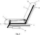
- Fig. 1 is schematically shown a bench according to the invention in a side view.
- the seat bench comprises a seat surface 1 and a backrest 2.
- the backrest 2 can be pivoted relative to the seat surface 1 about the first pivot axis 3 in the rear region of the seat surface 1.
- the seat 1 itself is pivotally mounted on the vehicle frame via the second pivot axis 4.
- the backrest 2 and the seat surface 1 are connected to one another in such a way that actuation via the servomotor 14 causes the backrest 2 and the seat surface 1 to be raised in an approximately vertical position.
- Various folding mechanisms are known for this in the prior art, such as the use of an actuating rod shown or the use of a chain or toothed belt system.
- the backrest 2 is composed of a backrest wall 10 and an upholstery 11.
- the upper backrest edge 5 is located at the upper end of the backrest 2, which lies opposite the first pivot axis 3.
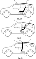
- FIGS. 2a-2c are schematic representations of the seat according to the invention in a motor vehicle, the transition from the normal position in Fig. 2a via an intermediate position as in Fig. 2b shown for the partition position Fig. 2c demonstrate.
- the partition position which in Fig. 2c is shown, the partition from the seat 1 and backrest 2 extends to the roof 6 of the vehicle.
- the partition position which in Fig. 2c is shown, the partition from the seat 1 and backrest 2 extends to the roof 6 of the vehicle.
- the partition element 15 In the direction of travel behind the contact line between the upper edge of the backrest 5 and the roof 6 there is a removable or displaceable (complete or, for example, in segments) roof element 15.
- the entire rear roof area can be removed up to the tailgate of the vehicle, or completely or in segments.
- the partition can also be removed from the partition position using the servomotor 14 Fig. 2c about the intermediate position of the Fig. 2b in the normal position, ie the formation of the usual seat 1
- Fig. 3 is a schematic representation showing a motor vehicle according to the invention with a seat in cross section.
- the seat 1 and the backrest 2 essentially cover the entire cross section of the vehicle.
- the now raised loading floor element 12 which is located at the same height in the partition wall position shown with an already existing loading floor 13.
- Transparent areas 9 are formed in the backrest 2 in that these areas have no upholstery or transparent upholstery and any backrest wall which may be present is made transparent.
- the backrest 2 is fixed on the roof 6 of the vehicle with the aid of fixing elements 8.
- sealing elements 7 are located between the seat surface 1 or the backrest 2 and the frame of the motor vehicle, that is to say the roof, the side walls and possibly — not shown — the loading floor element 12 arranged. This seals the contact surfaces between the partition and the vehicle.
- Fig. 4 finally shows the kinematics of the loading floor lift in a schematic flow diagram.
- the loading floor element 12 is still clearly below the normal loading floor 13, which forms the floor of a loading space behind the seat.
- the loading floor element 12 is raised to the height of the loading floor 13 via the servomotor 14 and the correspondingly mounted linkage on the vehicle, as shown in FIG Fig. 4 shown.
- the invention thus represents a motor vehicle with a seat which enables a separation between a front and a rear area in the motor vehicle in a simple, inexpensive and space-saving manner.
Landscapes
- Engineering & Computer Science (AREA)
- Mechanical Engineering (AREA)
- Aviation & Aerospace Engineering (AREA)
- Transportation (AREA)
- Seats For Vehicles (AREA)
- Vehicle Step Arrangements And Article Storage (AREA)
Claims (10)
- Véhicule automobile doté d'un banc comprenant une surface de siège (1) approximativement horizontale dans une position normale et un dossier (2) approximativement vertical dans la position normale, dans lequel la surface de siège (1) et le dossier (2) peuvent être réglés dans une position de cloison dans laquelle la surface de siège (1) et le dossier (2) adoptent une position au moins approximativement verticale et le dossier (2) est disposé au-dessus de la surface de siège (1), dans lequel, dans la position de cloison, le bord supérieur de dossier (5) est en contact avec le toit (6) du véhicule automobile de sorte que le dossier (2) forme avec la surface de siège (1) une cloison séparant la partie derrière la cloison, vue dans le sens de la marche, de la partie devant la cloison, vue dans le sens de la marche, dans lequel la cloison, dans la position de cloison, sépare de manière approximativement insonorisée, étanche à l'eau et/ou étanche à l'air la partie derrière la cloison, vue dans le sens de la marche, de la partie devant la cloison, vue dans le sens de la marche, au moyen d'un ou de plusieurs éléments d'étanchéité disposés entre la surface de siège (1) et le dossier (2) d'une part et le châssis du véhicule automobile, donc du toit et des parois latérales d'autre part, caractérisé en ce qu'un élément de plateau de chargement plat (12), qui se trouve dans la position normale du banc substantiellement sous la surface de siège (1), est relevé dans la position de cloison du banc de sorte que l'élément de plateau de chargement (12) dans la position de cloison est situé dans un plan avec un plateau de chargement (13) du véhicule automobile, la surface de siège (1) et le dossier (2) étant réglables dans la position de cloison par un servomoteur (14), le servomoteur (14) permettant de relever l'élément de plateau de chargement (12) en même temps que la surface de siège (1) et le dossier (2) peuvent être réglés dans la position de cloison.
- Véhicule automobile doté d'un banc selon la revendication 1, caractérisé en ce que le dossier (2) est monté pivotant sur la surface de siège (1) par l'intermédiaire d'un premier axe de pivotement (3) dans la partie arrière de la surface de siège (1), et la surface de siège (1) est montée pivotante sur le châssis de véhicule par l'intermédiaire d'un deuxième axe de pivotement (4) dans la partie avant de la surface de siège (1), et en ce que la surface de siège (1) et le dossier (2) peuvent pivoter autour des premier et deuxième axes de pivotement (3, 4) dans la position de cloison.
- Véhicule automobile doté d'un banc selon la revendication 1, caractérisé en ce que le bord supérieur de dossier (5) s'étend sur toute la largeur du toit (6) du véhicule automobile, et le bord supérieur de dossier (5) est en contact avec le toit (6) du véhicule automobile sur toute la largeur, dans la position de cloison.
- Véhicule automobile doté d'un banc selon la revendication 1, caractérisé en ce que la surface de siège (1) et le dossier (2) sont réalisés de telle sorte que dans la position de cloison, la cloison recouvre toute la section transversale du véhicule automobile.
- Véhicule automobile doté d'un banc selon la revendication 1, caractérisé en ce qu'à l'intérieur du véhicule automobile est disposé au moins un élément de fixation (8) agencé pour fixer au véhicule automobile, dans la position de cloison, le dossier (2) et/ou la surface de siège (1) dans la position au moins approximativement verticale.
- Véhicule automobile doté d'un banc selon la revendication 1, caractérisé en ce que le dossier (2) comprend au moins une partie transparente (9) réalisée de telle sorte qu'il est possible de voir depuis la partie devant la cloison, vue dans le sens de la marche, la partie devant la cloison, vue dans le sens de la marche.
- Véhicule automobile doté d'un banc selon la revendication 6, caractérisé en ce que le dossier (2) comprend un panneau arrière de dossier (10) et le panneau arrière de dossier (10) est réalisé dans un matériau transparent, en particulier en verre ou en plastique, dans ladite au moins une partie transparente (9) .
- Véhicule automobile doté d'un banc selon la revendication 6, caractérisé en ce que le dossier (2) comprend un rembourrage (11).
- Véhicule automobile doté d'un banc selon la revendication 8, caractérisé en ce que dans ladite au moins une partie transparente (9), le rembourrage (11) peut être retiré, en particulier escamoté.
- Véhicule automobile doté d'un banc selon la revendication 8, caractérisé en ce que dans ladite au moins une partie transparente (9), le rembourrage (11) est formé à partir d'un capitonnage transparent rempli d'air.
Priority Applications (5)
| Application Number | Priority Date | Filing Date | Title |
|---|---|---|---|
| EP12154890.3A EP2626236B1 (fr) | 2012-02-10 | 2012-02-10 | Véhicule automobile doté d'un banc |
| CN201310045453.1A CN103241149B (zh) | 2012-02-10 | 2013-02-05 | 具有靠背座椅的机动车辆 |
| JP2013020451A JP5696169B2 (ja) | 2012-02-10 | 2013-02-05 | 座席ベンチを備えた車両 |
| KR1020130014372A KR101407102B1 (ko) | 2012-02-10 | 2013-02-08 | 시트 벤치를 구비한 자동차 |
| US13/763,869 US8985665B2 (en) | 2012-02-10 | 2013-02-11 | Motor vehicle with a seat bench |
Applications Claiming Priority (1)
| Application Number | Priority Date | Filing Date | Title |
|---|---|---|---|
| EP12154890.3A EP2626236B1 (fr) | 2012-02-10 | 2012-02-10 | Véhicule automobile doté d'un banc |
Publications (2)
| Publication Number | Publication Date |
|---|---|
| EP2626236A1 EP2626236A1 (fr) | 2013-08-14 |
| EP2626236B1 true EP2626236B1 (fr) | 2020-04-01 |
Family
ID=45592214
Family Applications (1)
| Application Number | Title | Priority Date | Filing Date |
|---|---|---|---|
| EP12154890.3A Active EP2626236B1 (fr) | 2012-02-10 | 2012-02-10 | Véhicule automobile doté d'un banc |
Country Status (5)
| Country | Link |
|---|---|
| US (1) | US8985665B2 (fr) |
| EP (1) | EP2626236B1 (fr) |
| JP (1) | JP5696169B2 (fr) |
| KR (1) | KR101407102B1 (fr) |
| CN (1) | CN103241149B (fr) |
Families Citing this family (8)
| Publication number | Priority date | Publication date | Assignee | Title |
|---|---|---|---|---|
| US8973999B2 (en) * | 2012-03-27 | 2015-03-10 | Ford Global Technologies, Llc | Reclining vehicle seat with actuator and motor |
| JP2015229483A (ja) * | 2014-06-07 | 2015-12-21 | トヨタ自動車東日本株式会社 | 車両用衝立及び車両 |
| GB2539500B (en) * | 2015-06-19 | 2019-08-21 | Jaguar Land Rover Ltd | Improvements relating to automotive bulkheads |
| GB2555103B (en) * | 2016-10-14 | 2019-05-08 | Ford Global Tech Llc | A motor vehicle having a multi-functional vehicle seat |
| KR102167568B1 (ko) | 2020-03-11 | 2020-10-20 | 톈진 나가르 메커니컬 인더스트리 리미티드 컴퍼니 | 고압 플런저 방식 더블 다이아프램 펌프 |
| KR102167561B1 (ko) | 2020-03-11 | 2020-10-20 | 톈진 나가르 메커니컬 인더스트리 리미티드 컴퍼니 | 고압 플런저 방식 싱글 다이아프램 펌프 |
| US11926248B2 (en) | 2022-01-10 | 2024-03-12 | Faurecia Automotive Seating, Llc | Vehicle and occupant support for a vehicle |
| US11820265B2 (en) | 2022-02-03 | 2023-11-21 | Brose Fahrzeugteile SE & Co. Kommanditgesellschaft, Coburg | Vehicle seat |
Family Cites Families (27)
| Publication number | Priority date | Publication date | Assignee | Title |
|---|---|---|---|---|
| DE699589C (de) * | 1937-08-25 | 1940-12-02 | Heinz Doerpmund Dipl Ing | Fahrzeugkasten fuer geschlossene Personenkraftfahrzeuge |
| US3703310A (en) * | 1971-06-01 | 1972-11-21 | Gen Motors Corp | Dual configuration vehicle body |
| JPS61147629A (ja) | 1984-12-21 | 1986-07-05 | Toshiba Corp | パタ−ン検出回路 |
| JPH0428268Y2 (fr) * | 1985-03-06 | 1992-07-08 | ||
| JPH0524606Y2 (fr) * | 1988-08-29 | 1993-06-22 | ||
| FR2663270B1 (fr) * | 1990-06-13 | 1992-09-18 | Durisotti Sa | Siege et notamment banquette repliable pour vehicules automobiles. |
| DE4128554A1 (de) * | 1990-09-08 | 1992-03-12 | Volkswagen Ag | Trennwand fuer ein kombifahrzeug |
| JPH0653301U (ja) * | 1992-12-31 | 1994-07-19 | 株式会社タチエス | 間仕切り兼用自動車用シート |
| JPH11342793A (ja) * | 1998-06-04 | 1999-12-14 | Honda Motor Co Ltd | 自動車における車室密閉構造 |
| JP2000071830A (ja) * | 1998-08-28 | 2000-03-07 | Mazda Motor Corp | 自動車の車体構造 |
| JP2001026241A (ja) * | 1999-07-14 | 2001-01-30 | Mazda Motor Corp | 車両の後部車体構造 |
| FR2803565B1 (fr) * | 2000-01-06 | 2002-05-24 | Peugeot Citroen Automobiles Sa | Vehicule transformable en pick up |
| AUPQ597500A0 (en) * | 2000-03-02 | 2000-03-23 | Camatic Pty. Limited | Improved theatre chair |
| DE10039789C2 (de) | 2000-08-16 | 2003-03-06 | Daimler Chrysler Ag | Kraftfahrzeug, insbesondere Personenkraftwagen |
| US6485094B2 (en) * | 2000-12-06 | 2002-11-26 | Asc Incorporated | Automotive vehicle open air system |
| US6305741B1 (en) * | 2001-04-02 | 2001-10-23 | Martin Fernandez | Foldable chair with handle |
| AU2003228311A1 (en) * | 2002-03-14 | 2003-09-29 | Intier Automotive Inc. | Drop down stow in floor automotive vehicle seat assembly |
| DE10320527B3 (de) * | 2003-04-30 | 2004-12-09 | Bos Gmbh & Co. Kg | Trennvorrichtung für einen Fahrzeuginnenraum |
| FR2874867A1 (fr) * | 2004-09-07 | 2006-03-10 | Renault Sas | Agencement de siege basculant pour un habitacle de vehicule automobile |
| FR2876637B1 (fr) * | 2004-10-14 | 2007-02-02 | Productions Sa Sa B V | Cloison de separation amovible pour vehicule utilitaire, vehicule utilitaire equipe d'une telle cloison |
| JP2008105547A (ja) * | 2006-10-25 | 2008-05-08 | Nissan Motor Co Ltd | 自動車の車室後部構造 |
| JP5191713B2 (ja) * | 2007-09-26 | 2013-05-08 | トヨタ紡織株式会社 | 天井格納式シート |
| JP2009107372A (ja) * | 2007-10-26 | 2009-05-21 | Toyota Boshoku Corp | 天井格納式シート |
| US7559667B2 (en) * | 2007-10-26 | 2009-07-14 | Dean Alan Holderman | Lighted cushion |
| FR2923188B1 (fr) * | 2007-11-02 | 2010-01-22 | Productions S A B V | Dispositif de separation pour la protection des passagers dans un vehicule |
| US7762604B1 (en) * | 2009-02-20 | 2010-07-27 | Honda Motor Co., Ltd. | Vehicle seating arrangement |
| DE102010022206A1 (de) * | 2010-05-20 | 2011-11-24 | Brose Fahrzeugteile Gmbh & Co. Kommanditgesellschaft, Coburg | Kraftfahrzeug mit einer Rückbank |
-
2012
- 2012-02-10 EP EP12154890.3A patent/EP2626236B1/fr active Active
-
2013
- 2013-02-05 JP JP2013020451A patent/JP5696169B2/ja active Active
- 2013-02-05 CN CN201310045453.1A patent/CN103241149B/zh active Active
- 2013-02-08 KR KR1020130014372A patent/KR101407102B1/ko not_active Expired - Fee Related
- 2013-02-11 US US13/763,869 patent/US8985665B2/en active Active
Non-Patent Citations (1)
| Title |
|---|
| None * |
Also Published As
| Publication number | Publication date |
|---|---|
| JP5696169B2 (ja) | 2015-04-08 |
| CN103241149B (zh) | 2017-09-19 |
| KR20130092493A (ko) | 2013-08-20 |
| CN103241149A (zh) | 2013-08-14 |
| EP2626236A1 (fr) | 2013-08-14 |
| JP2013166543A (ja) | 2013-08-29 |
| KR101407102B1 (ko) | 2014-06-13 |
| US8985665B2 (en) | 2015-03-24 |
| US20130207428A1 (en) | 2013-08-15 |
Similar Documents
| Publication | Publication Date | Title |
|---|---|---|
| EP2626236B1 (fr) | Véhicule automobile doté d'un banc | |
| DE102017011996B3 (de) | Kraftwagen mit einem über eine Türöffnung zugänglichen Innenraum | |
| DE10204859A1 (de) | Klappdach mit Stauraumabdeckung | |
| EP0779172B1 (fr) | Voiture convertible avec deux sièges avant et banquette arrière | |
| WO2012025452A1 (fr) | Toit ouvrant à relevage pour véhicule présentant une ouverture de toit dans laquelle est disposé un longeron central | |
| DE10029926C2 (de) | Armlehne für einen Kraftfahrzeugsitz | |
| DE102009035078A1 (de) | Kompaktes Kraftfahrzeug | |
| EP1634748B1 (fr) | Système de toit pour un véhicule avec au moins deux éléments de toit rigides | |
| DE202006020522U9 (de) | Fahrzeug mit einer Vorrichtung zur Erleichterung eines Einstiegs/Ausstiegs | |
| DE112016004955B4 (de) | Fahrzeugheckstruktur | |
| EP3224074A1 (fr) | Véhicule automobile | |
| DE4325306C2 (de) | Windschottanordnung für ein Cabriolet | |
| EP1215066B1 (fr) | Toit de véhicule avec au moins une ouverture de toit et au moins un panneau amovible | |
| EP2626237B1 (fr) | Véhicule automobile doté d'un banc | |
| DE10134593A1 (de) | Verstellbares Fahrzeugdach mit aufblasbaren Kammern | |
| DE102005037911B3 (de) | Dachsystem für einen Personenkraftwagen | |
| DE102018215733A1 (de) | Sitzbank eines Fahrzeugs und Fahrzeug | |
| EP1736343B1 (fr) | Déflecteur de vent pour un cabriolet | |
| DE102005028802A1 (de) | Cabriolet-Fahrzeug mit einem hinteren Dachteil | |
| DE19811884B4 (de) | Personenkraftwagen | |
| DE10355056B3 (de) | Kraftfahrzeugsitz mit verschiebbarer Rückseitenabdeckung | |
| DE102022001885B4 (de) | Fahrzeug | |
| DE102019211820B4 (de) | Sitzanordnung | |
| DE102009035833A1 (de) | Fahrzeugsitz | |
| WO2006072272A1 (fr) | Véhicule automobile à toit ouvrant |
Legal Events
| Date | Code | Title | Description |
|---|---|---|---|
| PUAI | Public reference made under article 153(3) epc to a published international application that has entered the european phase |
Free format text: ORIGINAL CODE: 0009012 |
|
| 17P | Request for examination filed |
Effective date: 20121220 |
|
| AK | Designated contracting states |
Kind code of ref document: A1 Designated state(s): AL AT BE BG CH CY CZ DE DK EE ES FI FR GB GR HR HU IE IS IT LI LT LU LV MC MK MT NL NO PL PT RO RS SE SI SK SM TR |
|
| AX | Request for extension of the european patent |
Extension state: BA ME |
|
| RBV | Designated contracting states (corrected) |
Designated state(s): AL AT BE BG CH CY CZ DE DK EE ES FI FR GB GR HR HU IE IS IT LI LT LU LV MC MK MT NL NO PL PT RO RS SE SI SK SM TR |
|
| STAA | Information on the status of an ep patent application or granted ep patent |
Free format text: STATUS: EXAMINATION IS IN PROGRESS |
|
| 17Q | First examination report despatched |
Effective date: 20171205 |
|
| GRAP | Despatch of communication of intention to grant a patent |
Free format text: ORIGINAL CODE: EPIDOSNIGR1 |
|
| STAA | Information on the status of an ep patent application or granted ep patent |
Free format text: STATUS: GRANT OF PATENT IS INTENDED |
|
| INTG | Intention to grant announced |
Effective date: 20200120 |
|
| GRAS | Grant fee paid |
Free format text: ORIGINAL CODE: EPIDOSNIGR3 |
|
| GRAA | (expected) grant |
Free format text: ORIGINAL CODE: 0009210 |
|
| STAA | Information on the status of an ep patent application or granted ep patent |
Free format text: STATUS: THE PATENT HAS BEEN GRANTED |
|
| AK | Designated contracting states |
Kind code of ref document: B1 Designated state(s): AL AT BE BG CH CY CZ DE DK EE ES FI FR GB GR HR HU IE IS IT LI LT LU LV MC MK MT NL NO PL PT RO RS SE SI SK SM TR |
|
| REG | Reference to a national code |
Ref country code: GB Ref legal event code: FG4D Free format text: NOT ENGLISH |
|
| REG | Reference to a national code |
Ref country code: AT Ref legal event code: REF Ref document number: 1250937 Country of ref document: AT Kind code of ref document: T Effective date: 20200415 Ref country code: CH Ref legal event code: EP |
|
| REG | Reference to a national code |
Ref country code: DE Ref legal event code: R096 Ref document number: 502012015908 Country of ref document: DE |
|
| REG | Reference to a national code |
Ref country code: IE Ref legal event code: FG4D Free format text: LANGUAGE OF EP DOCUMENT: GERMAN |
|
| PG25 | Lapsed in a contracting state [announced via postgrant information from national office to epo] |
Ref country code: BG Free format text: LAPSE BECAUSE OF FAILURE TO SUBMIT A TRANSLATION OF THE DESCRIPTION OR TO PAY THE FEE WITHIN THE PRESCRIBED TIME-LIMIT Effective date: 20200701 |
|
| REG | Reference to a national code |
Ref country code: NL Ref legal event code: MP Effective date: 20200401 |
|
| REG | Reference to a national code |
Ref country code: LT Ref legal event code: MG4D |
|
| PG25 | Lapsed in a contracting state [announced via postgrant information from national office to epo] |
Ref country code: PT Free format text: LAPSE BECAUSE OF FAILURE TO SUBMIT A TRANSLATION OF THE DESCRIPTION OR TO PAY THE FEE WITHIN THE PRESCRIBED TIME-LIMIT Effective date: 20200817 Ref country code: LT Free format text: LAPSE BECAUSE OF FAILURE TO SUBMIT A TRANSLATION OF THE DESCRIPTION OR TO PAY THE FEE WITHIN THE PRESCRIBED TIME-LIMIT Effective date: 20200401 Ref country code: NO Free format text: LAPSE BECAUSE OF FAILURE TO SUBMIT A TRANSLATION OF THE DESCRIPTION OR TO PAY THE FEE WITHIN THE PRESCRIBED TIME-LIMIT Effective date: 20200701 Ref country code: FI Free format text: LAPSE BECAUSE OF FAILURE TO SUBMIT A TRANSLATION OF THE DESCRIPTION OR TO PAY THE FEE WITHIN THE PRESCRIBED TIME-LIMIT Effective date: 20200401 Ref country code: GR Free format text: LAPSE BECAUSE OF FAILURE TO SUBMIT A TRANSLATION OF THE DESCRIPTION OR TO PAY THE FEE WITHIN THE PRESCRIBED TIME-LIMIT Effective date: 20200702 Ref country code: SE Free format text: LAPSE BECAUSE OF FAILURE TO SUBMIT A TRANSLATION OF THE DESCRIPTION OR TO PAY THE FEE WITHIN THE PRESCRIBED TIME-LIMIT Effective date: 20200401 Ref country code: IS Free format text: LAPSE BECAUSE OF FAILURE TO SUBMIT A TRANSLATION OF THE DESCRIPTION OR TO PAY THE FEE WITHIN THE PRESCRIBED TIME-LIMIT Effective date: 20200801 Ref country code: NL Free format text: LAPSE BECAUSE OF FAILURE TO SUBMIT A TRANSLATION OF THE DESCRIPTION OR TO PAY THE FEE WITHIN THE PRESCRIBED TIME-LIMIT Effective date: 20200401 Ref country code: CZ Free format text: LAPSE BECAUSE OF FAILURE TO SUBMIT A TRANSLATION OF THE DESCRIPTION OR TO PAY THE FEE WITHIN THE PRESCRIBED TIME-LIMIT Effective date: 20200401 |
|
| PG25 | Lapsed in a contracting state [announced via postgrant information from national office to epo] |
Ref country code: RS Free format text: LAPSE BECAUSE OF FAILURE TO SUBMIT A TRANSLATION OF THE DESCRIPTION OR TO PAY THE FEE WITHIN THE PRESCRIBED TIME-LIMIT Effective date: 20200401 Ref country code: HR Free format text: LAPSE BECAUSE OF FAILURE TO SUBMIT A TRANSLATION OF THE DESCRIPTION OR TO PAY THE FEE WITHIN THE PRESCRIBED TIME-LIMIT Effective date: 20200401 Ref country code: LV Free format text: LAPSE BECAUSE OF FAILURE TO SUBMIT A TRANSLATION OF THE DESCRIPTION OR TO PAY THE FEE WITHIN THE PRESCRIBED TIME-LIMIT Effective date: 20200401 |
|
| PG25 | Lapsed in a contracting state [announced via postgrant information from national office to epo] |
Ref country code: AL Free format text: LAPSE BECAUSE OF FAILURE TO SUBMIT A TRANSLATION OF THE DESCRIPTION OR TO PAY THE FEE WITHIN THE PRESCRIBED TIME-LIMIT Effective date: 20200401 |
|
| REG | Reference to a national code |
Ref country code: DE Ref legal event code: R097 Ref document number: 502012015908 Country of ref document: DE |
|
| PG25 | Lapsed in a contracting state [announced via postgrant information from national office to epo] |
Ref country code: SM Free format text: LAPSE BECAUSE OF FAILURE TO SUBMIT A TRANSLATION OF THE DESCRIPTION OR TO PAY THE FEE WITHIN THE PRESCRIBED TIME-LIMIT Effective date: 20200401 Ref country code: EE Free format text: LAPSE BECAUSE OF FAILURE TO SUBMIT A TRANSLATION OF THE DESCRIPTION OR TO PAY THE FEE WITHIN THE PRESCRIBED TIME-LIMIT Effective date: 20200401 Ref country code: RO Free format text: LAPSE BECAUSE OF FAILURE TO SUBMIT A TRANSLATION OF THE DESCRIPTION OR TO PAY THE FEE WITHIN THE PRESCRIBED TIME-LIMIT Effective date: 20200401 Ref country code: IT Free format text: LAPSE BECAUSE OF FAILURE TO SUBMIT A TRANSLATION OF THE DESCRIPTION OR TO PAY THE FEE WITHIN THE PRESCRIBED TIME-LIMIT Effective date: 20200401 Ref country code: DK Free format text: LAPSE BECAUSE OF FAILURE TO SUBMIT A TRANSLATION OF THE DESCRIPTION OR TO PAY THE FEE WITHIN THE PRESCRIBED TIME-LIMIT Effective date: 20200401 Ref country code: ES Free format text: LAPSE BECAUSE OF FAILURE TO SUBMIT A TRANSLATION OF THE DESCRIPTION OR TO PAY THE FEE WITHIN THE PRESCRIBED TIME-LIMIT Effective date: 20200401 |
|
| PLBE | No opposition filed within time limit |
Free format text: ORIGINAL CODE: 0009261 |
|
| STAA | Information on the status of an ep patent application or granted ep patent |
Free format text: STATUS: NO OPPOSITION FILED WITHIN TIME LIMIT |
|
| PG25 | Lapsed in a contracting state [announced via postgrant information from national office to epo] |
Ref country code: SK Free format text: LAPSE BECAUSE OF FAILURE TO SUBMIT A TRANSLATION OF THE DESCRIPTION OR TO PAY THE FEE WITHIN THE PRESCRIBED TIME-LIMIT Effective date: 20200401 Ref country code: PL Free format text: LAPSE BECAUSE OF FAILURE TO SUBMIT A TRANSLATION OF THE DESCRIPTION OR TO PAY THE FEE WITHIN THE PRESCRIBED TIME-LIMIT Effective date: 20200401 |
|
| 26N | No opposition filed |
Effective date: 20210112 |
|
| PG25 | Lapsed in a contracting state [announced via postgrant information from national office to epo] |
Ref country code: SI Free format text: LAPSE BECAUSE OF FAILURE TO SUBMIT A TRANSLATION OF THE DESCRIPTION OR TO PAY THE FEE WITHIN THE PRESCRIBED TIME-LIMIT Effective date: 20200401 |
|
| PG25 | Lapsed in a contracting state [announced via postgrant information from national office to epo] |
Ref country code: MC Free format text: LAPSE BECAUSE OF FAILURE TO SUBMIT A TRANSLATION OF THE DESCRIPTION OR TO PAY THE FEE WITHIN THE PRESCRIBED TIME-LIMIT Effective date: 20200401 |
|
| GBPC | Gb: european patent ceased through non-payment of renewal fee |
Effective date: 20210210 |
|
| REG | Reference to a national code |
Ref country code: BE Ref legal event code: MM Effective date: 20210228 |
|
| PG25 | Lapsed in a contracting state [announced via postgrant information from national office to epo] |
Ref country code: LI Free format text: LAPSE BECAUSE OF NON-PAYMENT OF DUE FEES Effective date: 20210228 Ref country code: LU Free format text: LAPSE BECAUSE OF NON-PAYMENT OF DUE FEES Effective date: 20210210 Ref country code: CH Free format text: LAPSE BECAUSE OF NON-PAYMENT OF DUE FEES Effective date: 20210228 |
|
| PG25 | Lapsed in a contracting state [announced via postgrant information from national office to epo] |
Ref country code: GB Free format text: LAPSE BECAUSE OF NON-PAYMENT OF DUE FEES Effective date: 20210210 Ref country code: FR Free format text: LAPSE BECAUSE OF NON-PAYMENT OF DUE FEES Effective date: 20210228 Ref country code: IE Free format text: LAPSE BECAUSE OF NON-PAYMENT OF DUE FEES Effective date: 20210210 |
|
| REG | Reference to a national code |
Ref country code: AT Ref legal event code: MM01 Ref document number: 1250937 Country of ref document: AT Kind code of ref document: T Effective date: 20210210 |
|
| PG25 | Lapsed in a contracting state [announced via postgrant information from national office to epo] |
Ref country code: AT Free format text: LAPSE BECAUSE OF NON-PAYMENT OF DUE FEES Effective date: 20210210 |
|
| PG25 | Lapsed in a contracting state [announced via postgrant information from national office to epo] |
Ref country code: BE Free format text: LAPSE BECAUSE OF NON-PAYMENT OF DUE FEES Effective date: 20210228 |
|
| REG | Reference to a national code |
Ref country code: DE Ref legal event code: R081 Ref document number: 502012015908 Country of ref document: DE Owner name: MAGNA STEYR FAHRZEUGTECHNIK GMBH & CO KG, AT Free format text: FORMER OWNER: MAGNA STEYR FAHRZEUGTECHNIK AG & CO. KG, GRAZ, AT |
|
| PG25 | Lapsed in a contracting state [announced via postgrant information from national office to epo] |
Ref country code: HU Free format text: LAPSE BECAUSE OF FAILURE TO SUBMIT A TRANSLATION OF THE DESCRIPTION OR TO PAY THE FEE WITHIN THE PRESCRIBED TIME-LIMIT; INVALID AB INITIO Effective date: 20120210 Ref country code: CY Free format text: LAPSE BECAUSE OF FAILURE TO SUBMIT A TRANSLATION OF THE DESCRIPTION OR TO PAY THE FEE WITHIN THE PRESCRIBED TIME-LIMIT Effective date: 20200401 |
|
| PG25 | Lapsed in a contracting state [announced via postgrant information from national office to epo] |
Ref country code: MK Free format text: LAPSE BECAUSE OF FAILURE TO SUBMIT A TRANSLATION OF THE DESCRIPTION OR TO PAY THE FEE WITHIN THE PRESCRIBED TIME-LIMIT Effective date: 20200401 |
|
| PG25 | Lapsed in a contracting state [announced via postgrant information from national office to epo] |
Ref country code: TR Free format text: LAPSE BECAUSE OF FAILURE TO SUBMIT A TRANSLATION OF THE DESCRIPTION OR TO PAY THE FEE WITHIN THE PRESCRIBED TIME-LIMIT Effective date: 20200401 |
|
| PG25 | Lapsed in a contracting state [announced via postgrant information from national office to epo] |
Ref country code: MT Free format text: LAPSE BECAUSE OF FAILURE TO SUBMIT A TRANSLATION OF THE DESCRIPTION OR TO PAY THE FEE WITHIN THE PRESCRIBED TIME-LIMIT Effective date: 20200401 |
|
| REG | Reference to a national code |
Ref country code: DE Ref legal event code: R082 Ref document number: 502012015908 Country of ref document: DE Representative=s name: EULER, MATTHIAS, DR., DE |
|
| PGFP | Annual fee paid to national office [announced via postgrant information from national office to epo] |
Ref country code: DE Payment date: 20260218 Year of fee payment: 15 |