EP2626563A2 - Pompe, installation de recirculation pour une pompe et arbre de rotor pour une pompe - Google Patents
Pompe, installation de recirculation pour une pompe et arbre de rotor pour une pompe Download PDFInfo
- Publication number
- EP2626563A2 EP2626563A2 EP12176181.1A EP12176181A EP2626563A2 EP 2626563 A2 EP2626563 A2 EP 2626563A2 EP 12176181 A EP12176181 A EP 12176181A EP 2626563 A2 EP2626563 A2 EP 2626563A2
- Authority
- EP
- European Patent Office
- Prior art keywords
- pump
- recirculation
- separation
- pressure side
- shaft
- Prior art date
- Legal status (The legal status is an assumption and is not a legal conclusion. Google has not performed a legal analysis and makes no representation as to the accuracy of the status listed.)
- Granted
Links
Images
Classifications
-
- F—MECHANICAL ENGINEERING; LIGHTING; HEATING; WEAPONS; BLASTING
- F04—POSITIVE - DISPLACEMENT MACHINES FOR LIQUIDS; PUMPS FOR LIQUIDS OR ELASTIC FLUIDS
- F04D—NON-POSITIVE-DISPLACEMENT PUMPS
- F04D29/00—Details, component parts, or accessories
- F04D29/70—Suction grids; Strainers; Dust separation; Cleaning
- F04D29/708—Suction grids; Strainers; Dust separation; Cleaning specially for liquid pumps
-
- F—MECHANICAL ENGINEERING; LIGHTING; HEATING; WEAPONS; BLASTING
- F04—POSITIVE - DISPLACEMENT MACHINES FOR LIQUIDS; PUMPS FOR LIQUIDS OR ELASTIC FLUIDS
- F04D—NON-POSITIVE-DISPLACEMENT PUMPS
- F04D29/00—Details, component parts, or accessories
- F04D29/06—Lubrication
-
- F—MECHANICAL ENGINEERING; LIGHTING; HEATING; WEAPONS; BLASTING
- F04—POSITIVE - DISPLACEMENT MACHINES FOR LIQUIDS; PUMPS FOR LIQUIDS OR ELASTIC FLUIDS
- F04D—NON-POSITIVE-DISPLACEMENT PUMPS
- F04D13/00—Pumping installations or systems
- F04D13/02—Units comprising pumps and their driving means
- F04D13/06—Units comprising pumps and their driving means the pump being electrically driven
- F04D13/08—Units comprising pumps and their driving means the pump being electrically driven for submerged use
- F04D13/086—Units comprising pumps and their driving means the pump being electrically driven for submerged use the pump and drive motor are both submerged
-
- F—MECHANICAL ENGINEERING; LIGHTING; HEATING; WEAPONS; BLASTING
- F04—POSITIVE - DISPLACEMENT MACHINES FOR LIQUIDS; PUMPS FOR LIQUIDS OR ELASTIC FLUIDS
- F04D—NON-POSITIVE-DISPLACEMENT PUMPS
- F04D29/00—Details, component parts, or accessories
- F04D29/06—Lubrication
- F04D29/061—Lubrication especially adapted for liquid pumps
-
- F—MECHANICAL ENGINEERING; LIGHTING; HEATING; WEAPONS; BLASTING
- F04—POSITIVE - DISPLACEMENT MACHINES FOR LIQUIDS; PUMPS FOR LIQUIDS OR ELASTIC FLUIDS
- F04D—NON-POSITIVE-DISPLACEMENT PUMPS
- F04D7/00—Pumps adapted for handling specific fluids, e.g. by selection of specific materials for pumps or pump parts
- F04D7/02—Pumps adapted for handling specific fluids, e.g. by selection of specific materials for pumps or pump parts of centrifugal type
- F04D7/04—Pumps adapted for handling specific fluids, e.g. by selection of specific materials for pumps or pump parts of centrifugal type the fluids being viscous or non-homogenous
-
- F—MECHANICAL ENGINEERING; LIGHTING; HEATING; WEAPONS; BLASTING
- F04—POSITIVE - DISPLACEMENT MACHINES FOR LIQUIDS; PUMPS FOR LIQUIDS OR ELASTIC FLUIDS
- F04D—NON-POSITIVE-DISPLACEMENT PUMPS
- F04D13/00—Pumping installations or systems
- F04D13/02—Units comprising pumps and their driving means
- F04D13/06—Units comprising pumps and their driving means the pump being electrically driven
- F04D13/0606—Canned motor pumps
-
- F—MECHANICAL ENGINEERING; LIGHTING; HEATING; WEAPONS; BLASTING
- F04—POSITIVE - DISPLACEMENT MACHINES FOR LIQUIDS; PUMPS FOR LIQUIDS OR ELASTIC FLUIDS
- F04D—NON-POSITIVE-DISPLACEMENT PUMPS
- F04D13/00—Pumping installations or systems
- F04D13/02—Units comprising pumps and their driving means
- F04D13/06—Units comprising pumps and their driving means the pump being electrically driven
- F04D13/0606—Canned motor pumps
- F04D13/062—Canned motor pumps pressure compensation between motor- and pump- compartment
Definitions
- the invention relates to a pump for conveying a pumping fluid in the form of a multiphase mixture and to a recirculation device for a pump according to the preamble of the independent claims 1 and 15.
- Prominent examples include a variety of other applications pumps for the promotion of multi-phase mixtures, such as to promote crude oil.
- Such pumps often need to be operated in very inaccessible locations, often many hundreds of meters, even up to a few thousand meters below the sea surface where the pumps are must be operated reliably under extreme conditions for considerable periods of time.
- a lubricant contaminated with sand can cause considerable damage to the parts to be lubricated, because the hard sand grains damage the surfaces of the components to be lubricated, which are often made of relatively soft metal which can eventually lead to failure of the pump.
- such parts to be lubricated, for example, with a sand-contaminated lubricant, especially to harden so that the sand contained in the lubricant can not damage the surfaces, or at least as far as the wear of the corresponding parts reduce, that reasonably long service life, so economically reasonable maintenance intervals can be achieved.
- the hardening of the corresponding parts such as the rotor shaft of an impeller of the pump or the rotor shaft bearing form static or rotating counterpart and bearing components, of course, a measure that is on the one hand very complex and therefore expensive and ultimately does not solve the problem actually because even Hardened parts with time of rubbing load, for example by sand contained in the lubricant, can not withstand long term.
- Another point is that, for example, the The width of the lubricant gaps between the rotating and / or static parts of the bearings often can not be reduced to the desirable level, because otherwise the harmful influence of hard, non-compressible ingredients such as sand would be so large that premature wear of the corresponding bearing would be inevitable.
- the fact that the bearing gaps are not optimally adjustable by such restrictions, the smoothness of the stored parts can be adversely affected, and not optimally adjusted lubricant gaps can cause harmful vibrations in the operating state, which ultimately can also lead to premature wear.
- Another from the EP12154903.4 known device provides to separate the pumping fluid by means of a separation device.
- the liquid and solid ingredients of the pumping fluid are separated from each other and the liquid components used as a lubricant for lubricating rotating parts of the pump, in particular for the lubrication of the rotor shaft of the pump rotor.
- Disadvantage of the device described is that only solid or liquid ingredients can be deposited, although gaseous ingredients adversely affect the lubricating behavior of the lubricant, because, for example, the viscosity, ie the viscosity of the pump fluid used as a lubricant for use as a lubricant poorly or not at all suitable is.
- the object of the invention is therefore to propose a pump for delivering a pumping fluid in the form of a multiphase mixture, wherein the pumping fluid can be used simultaneously for lubricating rotating parts of the pump, in particular for lubricating the rotor shaft of the pump rotor, wherein the known from the prior art harmful influences of the ingredients on the lubrication process are largely avoided.
- the invention thus relates to a pump for delivering a pumping fluid in
- a multi-phase mixture wherein in the operating state provided under an input pressure at a low pressure side of the pump pump fluid is conveyed by means of a rotatably mounted in a pump stator about a rotation axis pump rotor to a high pressure side of the pump, and a rotor shaft is arranged in such a shaft passage that between the Rotor shaft and the shaft passage in an annular gap, a lubricant film from a fluid formed from the pumping fluid can be formed, and on the rotor shaft, a separation device is provided, with which in the operating state to provide the lubricating fluid at the annular gap a predetermined amount of an ingredient by means of a centrifugal force separated from the pumping fluid is.
- a recirculation device is provided so that a gas can be recirculated with the aid of the separation device.
- a recirculation device with which a specifiable amount of a gas, in practice frequently natural gas, can be recirculated in the operating state.
- the gas which is separable from the pumping fluid, is essentially separated from the pumping fluid by means of the separation device and in particular by means of the centrifugal force acting in the separation device.
- the pumping fluid to be pumped by the pump may be a multiphase mixture comprising crude oil loaded with sand and natural gas, which is conveyed from a raw source through the pump into a collective storage, for example.
- the pumping fluid is in the rotating separation device acting there due to the rotation Subjected to centrifugal forces.
- the pumping fluid flows from the high-pressure side of the pump to the recirculation device, ie in the direction of a gas bank, where the gas is separated from the pumping fluid and from there flows in a certain direction, preferably in the direction of the high-pressure side of the pump.
- a highly enriched in gas phase of the pumping fluid is formed in the interior of the annular chamber, which is preferably discharged by means of a recirculation device according to the invention back to the high pressure side of the pump and non-gas enriched pumping fluid for lubrication, e.g. the rotor shaft is used.
- the removal of the lubricating fluid to be used for the lubrication takes place at a further outward diameter of the annular chamber of the separation device, where a phase of the pumping fluid has accumulated with low gas and sand concentration.
- a highly enriched with sand phase of the pumping fluid forms at the outer edge of the annular chamber of the separation device and is discharged from there via a corresponding Abscheidetechnisch preferably back to the low pressure side of the pump and not for lubrication, e.g. the rotor shaft used.
- any ingredients of the pumping fluid having the corresponding density differences with the separation device and the gaseous components with the Recirculation means are preferably recirculated to the high pressure side, so that for example the proportion of the pumping fluid to be used for lubrication, has a predetermined suitable viscosity, which is not too high or too low, because gaseous components with the recirculation means and with the aid of the separation device are removable.
- the present invention it is possible for the first time by the present invention, not only solid or liquid ingredients but also gaseous ingredients that adversely affect the lubrication behavior, soliedseparieren of the pumping fluid to be pumped and recirculate by means of the recirculation, the one of ingredients sufficiently purified phase the pumping fluid is provided, which can be used for lubrication of rotating parts of the pump, wherein the well-known from the prior art harmful influences of the ingredients are minimized to the lubrication process.
- mixing or solution phenomena may be relevant, which further positively influence the process of recirculation.
- gas fractions are dissolved in higher viscoses and / or in higher density fluid constituents or are enclosed, for example, in the form of bubbles and thus likewise separated off and recirculated by the recirculation device according to the invention.
- other processes known per se can contribute to the fact that not only components of lower density but also those of higher density can be deposited via the recirculation device, because they are entrained by the components of higher density.
- the shaft passage forms a shaft bearing and comprises a stationary bushing and a rotating shaft sleeve, wherein the annular gap between the stationary bushing and the rotating Shaft sleeve is formed.
- the shaft passage advantageously forms a throttle point.
- the advantage of this measure is that the throttle points, ie annular seals, which serve to separate pressure stages, constantly lubricate and stabilize the rotor and serve the pressure separation, so that the rotor is constantly lubricated during its circulating movement only with liquid.
- the recirculation device comprises a supply line, a recirculation line and a means for increasing the pressure, in particular a screw conveyor and / or a corrugated line.
- a means for pressure increase in the recirculation line ie the line is inside partially or completely fluted and / or has a screw conveyor, so, as the skilled artisan immediately understands, the pressure in the recirculation line, similar the effect of a throttle, is increased above the pressure of the high pressure side of the pump or a Gassenke.
- the recirculation means for supplying the pumping fluid into the recirculation means by means of a supply line to the high pressure side of the pump is fluidly connected, so that the pumping fluid flows in the operating state of the high pressure side of the pump to the recirculation device.
- the recirculation device is flow-connected via a recirculation line to the high-pressure side of the pump and / or a gas bank.
- the recirculation line is designed such that by means of the means for pressure increase, a pressure in the recirculation line higher than on the high pressure side of the pump and / or Gassenke can be produced and the gas from the recirculation device to the high pressure side and / or the Gassenke is conveyed, said for example, an area for collecting the gas, a gas collecting container, or a conduit which directs the gas into an area outside the pump is to be understood, for example.
- the recirculation device is designed as an integral part of the pump.
- the supply and recirculation can be, for example, an integral part of the pump housing, in particular a running in the pump housing or pump stator or shaft passage bore or hole-like connection opening, or be realized by separate lines, the high pressure side with the recirculation device and / or the separation chamber connect.
- the separation device co-rotating with the rotor shaft about the axis of rotation comprises an annular chamber to which annular chamber for deposition of the ingredient a preferably tangentially oriented separation opening is provided.
- the separation device for separating the gas comprises a first separation opening and / or for depositing an ingredient a second separation opening and / or for separating the lubricating fluid a third separation opening.
- the first separation opening is fluidly connected to the recirculation means and / or the recirculation conduit for separation of the gas, so that while the second separation opening for discharging the ingredient is flow connected to the low pressure side of the pump by means of a separation line.
- a gas-enriched phase of the pumping fluid forms in the interior of the annular chamber of the separation device at the first separation opening.
- the removal of the lubricating fluid to be used for the lubrication takes place at the third separation opening, a further outward diameter of the annular chamber of the separation device, where a phase of the pumping fluid with low gas and solid concentration, such as sand, has accumulated.
- a highly enriched with sand phase of the pumping fluid is formed at the outer edge of the annular chamber of the separation device and is preferred from there via the second separation opening and a corresponding Abscheidetechnisch is discharged back to the low pressure side of the pump and not used for lubrication, for example, the rotor shaft.
- the recirculation and Abscheide apparently integral components of the pump housing, in particular in the pump housing or pump stator extending bores or hole-like connection openings, or the recirculation and Abscheide ein can also be realized by separate lines, the separation of the separation device with the recirculation / line and / or the low-pressure side of the pump or other points with low pressure connect.
- the shaft bushing in which the rotor shaft of the pump is mounted, or the annular gap between the stationary sleeve and rotating shaft sleeve can be optimally supplied with the cleaned of the ingredient phase of the pumping fluid for lubrication, the annular gap by means of a lubricant opening in such a way with the third separation opening fluidly connected to the separation device, that the lubrication fluid, which is at least partially freed from the ingredient, can be fed to the annular gap for lubrication of the shaft passage via the lubricant opening.
- an additional lubricant line can be provided such that a predeterminable amount of lubricating fluid can be discharged from the separation device, in particular can be used to supply a further lubrication point of the pump.
- the lubricant line in particular an integral part of the pump housing, in particular a running in the pump housing or pump stator bore or hole-like connection opening, or the lubricant line can also be realized by a separate line, the separation device of the separation chamber with the other lubrication point in the pump connects.
- the separation device can either be detachably connected to the rotor shaft, wherein the separation device can be designed, in particular, as a separation disk which can be screwed to the rotor shaft. It is of course also possible that the separation device is an integral part of the rotor shaft, wherein the separation device may be in particular a separation disc integrally connected to the rotor shaft.
- the invention further relates to a recirculation device for a pump according to the invention.
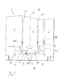
- Fig. 1 shows the state of the art by means of a pump, wherein the construction of the shaft passage with separation means something is shown in more detail in detail.
- the pump which is hereinafter referred to in its entirety by the reference numeral 1 ', generally serves to convey a pumping fluid 2' in the form of a multiphase mixture, ie the multiphase mixture consists of various solid, liquid and gaseous constituents.
- the ingredients are essentially sand and gas which are present as an impurity in the pumping fluid 2 'in intolerable amounts.
- the pumping fluid 2 ' here is petroleum, which under an inlet pressure at a low pressure side LP' of the pump 1 'is ready and in the operating state by means of a in a pump stator (not shown) about a rotation axis A' according to the arrow P rotatably mounted pump rotor (not shown ) is conveyed to a high pressure side HP 'of the pump 1'.
- the pump rotor is designed in such a way and arranged over a rotor shaft 5 'in a shaft passage 6' that between the rotor shaft 5 'and the shaft passage 6' in an annular gap 21 ', a lubricating film of a formed from the pumping fluid 2' lubricating fluid 200 'can be formed ,
- a separation device 7' is provided, with which in the operating state to provide the lubricating fluid 200 'a predetermined amount of the ingredient by means of a centrifugal force from the pumping fluid 2' is separable.
- Fig. 1 shown schematically is for supplying the constituent comprehensive pumping fluid 2 ', so here the petroleum, the separation device 7', which is configured as a with the rotor shaft 5 'of the pump 1' with screws 70 'screwed separation disc, via a feed line with the High pressure side HP 'of the pump 1' connected.
- the separation disk is covered by a cover D 'through which the pumping fluid 2' is fed to the separation disk.
- the separation disc of Fig. 1 shows in detail, with the rotor shaft 5 'about the rotation axis A' co-rotating separation disc an annular chamber, wherein at the annular chamber for the deposition of the ingredients at least one substantially tangentially oriented separation opening is provided.
- the separation opening is for discharging separated ingredient, so in the present example for discharging the enriched in oil sand, via a Abscheidetechnisch 721 'with the low pressure side LP' of the pump 1 'is connected.
- the sand has a higher density than the lubricating fluid 200 'which is finally used to lubricate the rotor shaft 5'.
- the annular gap 21' is fluidly connected to the separation device 7 'by means of a lubricant opening 22' in such a way that the lubricating fluid 200 ', at least partially freed from the sand, reaches the annular gap 21 'for lubricating the shaft passage 6' via the lubricant opening 22 'can be fed.
- a lubricant line 10 ' is additionally provided such that a predeterminable amount of lubricating fluid 200' can be discharged from the separation disk, in particular for feeding additional lubrication point of the pump 1 ', which additional lubricant locations are not explicitly shown for reasons of clarity.
- the lubricating fluid 200 'branched off via the lubricant line 10' is used for lubricating other parts of the system which lie outside the pump 1 'or are not part of the pump 1'.
- the separation device 7 ' in this case the separation disk, is detachably connected to the rotor shaft 5', but it is also possible that the separation device 7 'is an integral part of the rotor shaft 5', and the separation device 7 'in particular with the rotor shaft 5 'integrally connected separation disc.
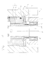
- the inventive pump is very general and in particular in the specific embodiment of the Fig. 2 and Fig. 3 the promotion of a pumping fluid in the form of a multi-phase mixture.
- the pump which is hereinafter referred to in its entirety by the reference numeral 1, is used in general Promotion of a pumping fluid 2 in the form of a multi-phase mixture, ie the pumping fluid consists of various solid, liquid and gaseous ingredients.
- the ingredients are essentially sand and gas which are present as an impurity in the pumping fluid 2 in intolerable amounts.
- the pumping fluid 2 for example, oil
- the pumping fluid 2 which is available under an inlet pressure at a low pressure side LP of the pump 1 and in the operating state by means of a rotatably mounted in a pump stator 3 about a rotation axis A according to the arrow P pump rotor 4 is conveyed to a high pressure side HP of the pump, and a rotor shaft 5 is arranged in such a shaft bushing 6, that between the rotor shaft 5 and the shaft passage 6 in an annular gap 21, a lubricating film of a lubricating fluid 200 formed from the pumping fluid 2 can be formed.
- a separation device 7 is provided on the rotor shaft 5, with which in the operating state for providing the lubricating fluid 200 at the annular gap 21 a predeterminable amount of an ingredient by means of a centrifugal force from the pumping fluid 2 is separable.
- a recirculation device 8 is provided so that a gas 201 can be recirculated with the aid of the separation device 7.
- the shaft passage 6 comprises a stationary sleeve 9 and a rotating shaft sleeve 10.
- the annular gap 21 is, as in the present embodiment, both between the stationary sleeve 9 and the rotating shaft sleeve 10 can be formed, as well as directly between the rotor shaft 5 and shaft passage 6 trainable.
- the in Fig. 2 illustrated recirculation device 8 a feed line 81, a recirculation line 82 and a means for pressure increase 83, in particular a screw conveyor and / or a corrugated pipe.
- the recirculation device 8 is fluidly connected to the high-pressure side HP of the pump by means of the supply line 81, so that the pumping fluid 2 flows from the high-pressure side HP of the pump to the recirculation device 8.
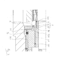
- the separation device 7 or the separation disk which rotates about the rotation axis A with the rotor shaft 5, comprises in detail an annular chamber to which annular chamber for deposition of the ingredient a preferably tangentially oriented separation opening is provided.
- the separation device 7 or separation disc for separating the gas 201 comprises a first separation opening 71 and / or for depositing an ingredient, a second separation opening 72 and / or for depositing the lubricating fluid, a third separation opening 73.
- the first separation opening 71 is flow-connected to the recirculation device 8 and / or recirculation line 82 for separating the gas 201.
- recirculation device 8 is fluidly connected by means of the recirculation line 82 to the high pressure side HP of the pump and / or a Gassenke.
- the pressure increase means 83 are required to generate a pressure in the recirculation line 82 which is higher than the high pressure side HP of the pump and / or the gas bank, so that the gas 201 from the recirculation device 8 to the high pressure side HP of the pump and / or the Gassenke is transportable.
- the recirculation device 8 is formed as an integral part in the pump stator 3, although it is also possible for the recirculation device 8 to be an external recirculation device 8 that is detachably connected to the pump.
- the annular gap 21 is fluidly connected to the third separation opening 73 of the separation device 7 by means of a lubricant opening 22, such that the lubricant fluid 200 at least partially freed from the content reaches the annular gap 21 for lubricating the shaft passage 6 via the lubricant opening 22 can be fed.
- a lubricant line is additionally provided such that a predeterminable amount of lubricating fluid 200 can be discharged from the separation disk, in particular for feeding further lubrication point of the pump 1, which additional lubricant points are not explicitly shown for reasons of clarity.
- the branched off via the lubricant line lubricating fluid 200 is used for lubrication of other parts of the system, which lie outside the pump 1 and are not part of the pump 1.
- the second separation opening 72 is connected to the discharge of separated ingredient, so in the present example for discharging the enriched in oil sand, via a Abscheidetechnisch 721 with the low pressure side LP of the pump 1.
- the sand has a higher density than the lubricating fluid 200 which is used for the lubrication of the rotor shaft 5.
- the Abscheidetechnisch 721 is formed as an integral part of the shaft passage 6 or the pump stator 3, but can also be performed as a separate additional Abscheide effet 721, for example, outside the housing of the pump.
- a second throttle point 74 is provided, which serves to increase the resistance in order to avoid a direct outflow of the pumping fluid 2.
Landscapes
- Engineering & Computer Science (AREA)
- Mechanical Engineering (AREA)
- General Engineering & Computer Science (AREA)
- Structures Of Non-Positive Displacement Pumps (AREA)
- Applications Or Details Of Rotary Compressors (AREA)
Priority Applications (3)
| Application Number | Priority Date | Filing Date | Title |
|---|---|---|---|
| EP12176181.1A EP2626563B1 (fr) | 2012-02-10 | 2012-07-12 | Pompe, installation de recirculation pour une pompe et arbre de rotor pour une pompe |
| US13/763,554 US9683575B2 (en) | 2012-02-10 | 2013-02-08 | Pump as well as a recirculation device for a pump |
| BR102013003795-8A BR102013003795B1 (pt) | 2012-02-10 | 2013-02-08 | Bomba e conjunto de recirculação para uma bomba |
Applications Claiming Priority (2)
| Application Number | Priority Date | Filing Date | Title |
|---|---|---|---|
| EP12154903 | 2012-02-10 | ||
| EP12176181.1A EP2626563B1 (fr) | 2012-02-10 | 2012-07-12 | Pompe, installation de recirculation pour une pompe et arbre de rotor pour une pompe |
Publications (3)
| Publication Number | Publication Date |
|---|---|
| EP2626563A2 true EP2626563A2 (fr) | 2013-08-14 |
| EP2626563A3 EP2626563A3 (fr) | 2018-03-21 |
| EP2626563B1 EP2626563B1 (fr) | 2020-06-03 |
Family
ID=46506266
Family Applications (2)
| Application Number | Title | Priority Date | Filing Date |
|---|---|---|---|
| EP12176181.1A Active EP2626563B1 (fr) | 2012-02-10 | 2012-07-12 | Pompe, installation de recirculation pour une pompe et arbre de rotor pour une pompe |
| EP13151407.7A Active EP2626564B1 (fr) | 2012-02-10 | 2013-01-16 | Pompe, dispositif de séparation pour une pompe, ainsi qu'arbre de rotor pour une pompe |
Family Applications After (1)
| Application Number | Title | Priority Date | Filing Date |
|---|---|---|---|
| EP13151407.7A Active EP2626564B1 (fr) | 2012-02-10 | 2013-01-16 | Pompe, dispositif de séparation pour une pompe, ainsi qu'arbre de rotor pour une pompe |
Country Status (4)
| Country | Link |
|---|---|
| US (2) | US9683575B2 (fr) |
| EP (2) | EP2626563B1 (fr) |
| BR (2) | BR102013003795B1 (fr) |
| ES (1) | ES2796733T3 (fr) |
Cited By (1)
| Publication number | Priority date | Publication date | Assignee | Title |
|---|---|---|---|---|
| EP3623633A1 (fr) | 2018-09-17 | 2020-03-18 | Sulzer Management AG | Pompe à phases multiples |
Families Citing this family (5)
| Publication number | Priority date | Publication date | Assignee | Title |
|---|---|---|---|---|
| US10393115B2 (en) * | 2012-09-12 | 2019-08-27 | Fmc Technologies, Inc. | Subsea multiphase pump or compressor with magnetic coupling and cooling or lubrication by liquid or gas extracted from process fluid |
| WO2014095291A1 (fr) * | 2012-12-20 | 2014-06-26 | Sulzer Pumpen Ag | Pompe polyphasique avec séparateur, avec lubrification et refroidissement de la pompe par le liquide de traitement |
| RU2716348C2 (ru) * | 2018-07-23 | 2020-03-11 | Акционерное общество "Гидрогаз" (АО "Гидрогаз") | Полупогружной насос с валопроводом на подшипниках скольжения |
| US11666680B2 (en) * | 2018-08-28 | 2023-06-06 | Aatru Medical, LLC | Dressing |
| NO346033B1 (en) | 2018-12-20 | 2022-01-10 | Fsubsea As | Subsea pump system with process lubricated bearings, related method and use |
Citations (1)
| Publication number | Priority date | Publication date | Assignee | Title |
|---|---|---|---|---|
| EP1215490A2 (fr) | 2000-12-18 | 2002-06-19 | Delphi Technologies, Inc. | Méthode de coulage en barbotine pour la fabrication de détecteurs de gaz d'échappement |
Family Cites Families (24)
| Publication number | Priority date | Publication date | Assignee | Title |
|---|---|---|---|---|
| US2830755A (en) * | 1955-05-23 | 1958-04-15 | Borg Warner | Rotary compressor |
| CH343727A (fr) * | 1957-04-25 | 1959-12-31 | Alsacienne Constr Meca | Dispositif pour assurer l'étanchéité autour d'un arbre rotatif traversant une paroi |
| US3203354A (en) * | 1962-03-26 | 1965-08-31 | Thiokol Chemical Corp | Pump |
| USRE26570E (en) * | 1962-11-09 | 1969-04-29 | Method and mechanism for lubricating the shaft elements of a pump rotor for pumping an abradant-containing liquid | |
| JPS403655B1 (fr) * | 1962-11-20 | 1965-02-26 | ||
| GB1071266A (en) * | 1963-10-15 | 1967-06-07 | Sigmund Pulsometer Pumps Ltd | Liquid-moving unit comprising a centrifugal pump and an electric driving motor therefor |
| CH557472A (de) * | 1972-09-13 | 1974-12-31 | Sulzer Ag | Turbopumpe. |
| US3867056A (en) * | 1973-09-27 | 1975-02-18 | Oil Dynamics Inc | Recirculating gas separation means for submersible oil well pumps |
| US4333748A (en) * | 1978-09-05 | 1982-06-08 | Baker International Corporation | Rotary gas/liquid separator |
| US4410337A (en) * | 1980-04-07 | 1983-10-18 | A. Ahlstrom Osakeyhtio | Method and an apparatus for separating a gas from a fibre suspension |
| FI73023C (fi) * | 1984-07-17 | 1987-08-10 | Ahlstroem Oy | Anordning foer avskiljande av gas ur en fibersuspension. |
| CH672007A5 (en) * | 1985-11-11 | 1989-10-13 | Hermetic Pumpen Gmbh | Vertical pump driven by glandless motor |
| US4795322A (en) * | 1987-11-27 | 1989-01-03 | Carrier Corporation | Scroll compressor with oil thrust force on orbiting scroll |
| US4854831A (en) * | 1987-11-27 | 1989-08-08 | Carrier Corporation | Scroll compressor with plural discharge flow paths |
| US4795321A (en) * | 1987-11-27 | 1989-01-03 | Carrier Corporation | Method of lubricating a scroll compressor |
| US4811471A (en) * | 1987-11-27 | 1989-03-14 | Carrier Corporation | Method of assembling scroll compressors |
| US4768936A (en) * | 1987-11-27 | 1988-09-06 | Carrier Corporation | Scroll compressor with oil pickup tube in oil sump |
| US4871301A (en) * | 1988-02-29 | 1989-10-03 | Ingersoll-Rand Company | Centrifugal pump bearing arrangement |
| JPH05504810A (ja) * | 1990-02-06 | 1993-07-22 | インガーソル ランド カンパニー | 遠心ポンプ潤滑材ストレーナ装置 |
| US5118466A (en) * | 1990-03-12 | 1992-06-02 | Westinghouse Electric Corp. | Nuclear reactor coolant pump with internal self-cooling arrangement |
| FI95540C (fi) * | 1990-09-25 | 1996-02-26 | Ahlstroem Oy | Menetelmä ja laite kaasun erottamiseksi kiintoainetta sisältävästä nesteestä |
| US5248245A (en) * | 1992-11-02 | 1993-09-28 | Ingersoll-Dresser Pump Company | Magnetically coupled centrifugal pump with improved casting and lubrication |
| DE50206223D1 (de) * | 2001-10-22 | 2006-05-18 | Sulzer Pumpen Ag | Wellenabdichtungsanordnung für eine Pumpe zur Förderung heisser Fluide |
| FI20050733A7 (fi) * | 2005-06-22 | 2006-12-23 | Sulzer Pumpen Ag | Kaasunerotuslaite, sen etuseinä ja erotuspyörä |
-
2012
- 2012-07-12 ES ES12176181T patent/ES2796733T3/es active Active
- 2012-07-12 EP EP12176181.1A patent/EP2626563B1/fr active Active
-
2013
- 2013-01-16 EP EP13151407.7A patent/EP2626564B1/fr active Active
- 2013-02-08 US US13/763,554 patent/US9683575B2/en active Active
- 2013-02-08 BR BR102013003795-8A patent/BR102013003795B1/pt active IP Right Grant
- 2013-02-08 BR BR102013003215-8A patent/BR102013003215B1/pt active IP Right Grant
- 2013-02-08 US US13/763,577 patent/US10082149B2/en active Active
Patent Citations (1)
| Publication number | Priority date | Publication date | Assignee | Title |
|---|---|---|---|---|
| EP1215490A2 (fr) | 2000-12-18 | 2002-06-19 | Delphi Technologies, Inc. | Méthode de coulage en barbotine pour la fabrication de détecteurs de gaz d'échappement |
Cited By (2)
| Publication number | Priority date | Publication date | Assignee | Title |
|---|---|---|---|---|
| EP3623633A1 (fr) | 2018-09-17 | 2020-03-18 | Sulzer Management AG | Pompe à phases multiples |
| US12135044B2 (en) | 2018-09-17 | 2024-11-05 | Sulzer Management Ag | Multiphase pump |
Also Published As
| Publication number | Publication date |
|---|---|
| US20130209226A1 (en) | 2013-08-15 |
| US20130315709A1 (en) | 2013-11-28 |
| BR102013003215A2 (pt) | 2015-07-14 |
| EP2626563A3 (fr) | 2018-03-21 |
| BR102013003215B1 (pt) | 2021-09-28 |
| BR102013003795A2 (pt) | 2015-06-16 |
| US10082149B2 (en) | 2018-09-25 |
| US9683575B2 (en) | 2017-06-20 |
| ES2796733T3 (es) | 2020-11-30 |
| EP2626564B1 (fr) | 2020-12-09 |
| EP2626563B1 (fr) | 2020-06-03 |
| BR102013003795B1 (pt) | 2021-11-03 |
| EP2626564A1 (fr) | 2013-08-14 |
Similar Documents
| Publication | Publication Date | Title |
|---|---|---|
| EP2626563B1 (fr) | Pompe, installation de recirculation pour une pompe et arbre de rotor pour une pompe | |
| EP2386767B1 (fr) | Pompe hélico-axiale et procédé pour supporter un rotor dans une pompe hélico-axiale | |
| DE69607718T2 (de) | Wälzlager mit dynamischer, ölversorgter Drainage | |
| WO2009130124A1 (fr) | Système de palier avec un roulement double, turbocompresseur et procédé pour amener un agent lubrifiant jusqu’aux rangées de corps de roulement d’un roulement double | |
| EP2060794B1 (fr) | Pompe à vide dotée d'une pompe à lubrifiant | |
| DE60124859T2 (de) | Schraubenkompressor mit wassereinspritzung | |
| EP0718541A1 (fr) | Procédé et dispositif pour auto-lubrifier des palier d'une turbocompresseur | |
| DE8717902U1 (de) | Radialverdichter zum Verdichten von Frischgas und Kreisgas | |
| DE102017109553A1 (de) | Kompressor mit kontaktfreien und kontaktabdichtungen | |
| EP2386766B1 (fr) | Pompe hélico-axiale, rotor pour une pompe hélico-axiale,palier hydrodynamique d'un rotor d'une pompe hélico-axiale et pompe hybride dotée d'un rotor pour une pompe hélico-axiale | |
| EP3121450A1 (fr) | Pompe de transport d'un fluide presentant une viscosite variable | |
| EP3094875B1 (fr) | Palier d'un arbre rotatif avec étanchéité | |
| DE2833167A1 (de) | Baueinheit, bestehend aus einer oelpumpe zur oelumlaufschmierung einer brennkraftmaschine und einer vakuumpumpe zur erzeugung eines vakuums fuer die bremskraftverstaerkung in kraftfahrzeugen | |
| DE112017001057T5 (de) | Gleit- bzw. radiallager und rotationsmaschine | |
| DE69716552T2 (de) | Dichtung/lagervorrichtung | |
| EP0135730B1 (fr) | Palier lisse hydrodynamique à auto-pompage | |
| DE3148579A1 (de) | Verfahren an einem schraubenkompressor mit oeleinspritzung | |
| DE102023116056A1 (de) | Kurbelwelle | |
| EP1649206B1 (fr) | Dispositif pour repartir un milieu visqueux transporte dans un flux gazeux, notamment un agent lubrifiant tel que de l'huile | |
| DE112013005092B4 (de) | Kupplungsbeölung | |
| EP0628725A2 (fr) | Pompe à engrenages | |
| DE102004030123B3 (de) | Schraubenspindelpumpe | |
| DE20311631U1 (de) | Vorrichtung zum Aufteilen eines in einer Gasströmung transportierten viskosen Mediums, insbesondere eines Schmiermittels wie Öl | |
| DE202006014618U1 (de) | Gleitringdichtung | |
| DE2901638C3 (fr) |
Legal Events
| Date | Code | Title | Description |
|---|---|---|---|
| PUAI | Public reference made under article 153(3) epc to a published international application that has entered the european phase |
Free format text: ORIGINAL CODE: 0009012 |
|
| AK | Designated contracting states |
Kind code of ref document: A2 Designated state(s): AL AT BE BG CH CY CZ DE DK EE ES FI FR GB GR HR HU IE IS IT LI LT LU LV MC MK MT NL NO PL PT RO RS SE SI SK SM TR |
|
| AX | Request for extension of the european patent |
Extension state: BA ME |
|
| RAP1 | Party data changed (applicant data changed or rights of an application transferred) |
Owner name: SULZER MANAGEMENT AG |
|
| PUAL | Search report despatched |
Free format text: ORIGINAL CODE: 0009013 |
|
| AK | Designated contracting states |
Kind code of ref document: A3 Designated state(s): AL AT BE BG CH CY CZ DE DK EE ES FI FR GB GR HR HU IE IS IT LI LT LU LV MC MK MT NL NO PL PT RO RS SE SI SK SM TR |
|
| AX | Request for extension of the european patent |
Extension state: BA ME |
|
| RIC1 | Information provided on ipc code assigned before grant |
Ipc: F04D 7/04 20060101AFI20180210BHEP Ipc: F04D 29/06 20060101ALI20180210BHEP |
|
| STAA | Information on the status of an ep patent application or granted ep patent |
Free format text: STATUS: REQUEST FOR EXAMINATION WAS MADE |
|
| 17P | Request for examination filed |
Effective date: 20180921 |
|
| RBV | Designated contracting states (corrected) |
Designated state(s): AL AT BE BG CH CY CZ DE DK EE ES FI FR GB GR HR HU IE IS IT LI LT LU LV MC MK MT NL NO PL PT RO RS SE SI SK SM TR |
|
| RIC1 | Information provided on ipc code assigned before grant |
Ipc: F04D 7/04 20060101AFI20191206BHEP Ipc: F04D 29/06 20060101ALI20191206BHEP |
|
| GRAP | Despatch of communication of intention to grant a patent |
Free format text: ORIGINAL CODE: EPIDOSNIGR1 |
|
| STAA | Information on the status of an ep patent application or granted ep patent |
Free format text: STATUS: GRANT OF PATENT IS INTENDED |
|
| INTG | Intention to grant announced |
Effective date: 20200130 |
|
| GRAS | Grant fee paid |
Free format text: ORIGINAL CODE: EPIDOSNIGR3 |
|
| GRAA | (expected) grant |
Free format text: ORIGINAL CODE: 0009210 |
|
| STAA | Information on the status of an ep patent application or granted ep patent |
Free format text: STATUS: THE PATENT HAS BEEN GRANTED |
|
| AK | Designated contracting states |
Kind code of ref document: B1 Designated state(s): AL AT BE BG CH CY CZ DE DK EE ES FI FR GB GR HR HU IE IS IT LI LT LU LV MC MK MT NL NO PL PT RO RS SE SI SK SM TR |
|
| REG | Reference to a national code |
Ref country code: GB Ref legal event code: FG4D Free format text: NOT ENGLISH |
|
| REG | Reference to a national code |
Ref country code: CH Ref legal event code: EP Ref country code: AT Ref legal event code: REF Ref document number: 1277283 Country of ref document: AT Kind code of ref document: T Effective date: 20200615 |
|
| REG | Reference to a national code |
Ref country code: DE Ref legal event code: R096 Ref document number: 502012016112 Country of ref document: DE |
|
| REG | Reference to a national code |
Ref country code: LT Ref legal event code: MG4D Ref country code: NO Ref legal event code: T2 Effective date: 20200603 |
|
| PG25 | Lapsed in a contracting state [announced via postgrant information from national office to epo] |
Ref country code: SE Free format text: LAPSE BECAUSE OF FAILURE TO SUBMIT A TRANSLATION OF THE DESCRIPTION OR TO PAY THE FEE WITHIN THE PRESCRIBED TIME-LIMIT Effective date: 20200603 Ref country code: LT Free format text: LAPSE BECAUSE OF FAILURE TO SUBMIT A TRANSLATION OF THE DESCRIPTION OR TO PAY THE FEE WITHIN THE PRESCRIBED TIME-LIMIT Effective date: 20200603 Ref country code: GR Free format text: LAPSE BECAUSE OF FAILURE TO SUBMIT A TRANSLATION OF THE DESCRIPTION OR TO PAY THE FEE WITHIN THE PRESCRIBED TIME-LIMIT Effective date: 20200904 Ref country code: FI Free format text: LAPSE BECAUSE OF FAILURE TO SUBMIT A TRANSLATION OF THE DESCRIPTION OR TO PAY THE FEE WITHIN THE PRESCRIBED TIME-LIMIT Effective date: 20200603 |
|
| REG | Reference to a national code |
Ref country code: NL Ref legal event code: MP Effective date: 20200603 |
|
| PG25 | Lapsed in a contracting state [announced via postgrant information from national office to epo] |
Ref country code: LV Free format text: LAPSE BECAUSE OF FAILURE TO SUBMIT A TRANSLATION OF THE DESCRIPTION OR TO PAY THE FEE WITHIN THE PRESCRIBED TIME-LIMIT Effective date: 20200603 Ref country code: HR Free format text: LAPSE BECAUSE OF FAILURE TO SUBMIT A TRANSLATION OF THE DESCRIPTION OR TO PAY THE FEE WITHIN THE PRESCRIBED TIME-LIMIT Effective date: 20200603 Ref country code: RS Free format text: LAPSE BECAUSE OF FAILURE TO SUBMIT A TRANSLATION OF THE DESCRIPTION OR TO PAY THE FEE WITHIN THE PRESCRIBED TIME-LIMIT Effective date: 20200603 Ref country code: BG Free format text: LAPSE BECAUSE OF FAILURE TO SUBMIT A TRANSLATION OF THE DESCRIPTION OR TO PAY THE FEE WITHIN THE PRESCRIBED TIME-LIMIT Effective date: 20200903 |
|
| REG | Reference to a national code |
Ref country code: ES Ref legal event code: FG2A Ref document number: 2796733 Country of ref document: ES Kind code of ref document: T3 Effective date: 20201130 |
|
| PG25 | Lapsed in a contracting state [announced via postgrant information from national office to epo] |
Ref country code: NL Free format text: LAPSE BECAUSE OF FAILURE TO SUBMIT A TRANSLATION OF THE DESCRIPTION OR TO PAY THE FEE WITHIN THE PRESCRIBED TIME-LIMIT Effective date: 20200603 Ref country code: AL Free format text: LAPSE BECAUSE OF FAILURE TO SUBMIT A TRANSLATION OF THE DESCRIPTION OR TO PAY THE FEE WITHIN THE PRESCRIBED TIME-LIMIT Effective date: 20200603 |
|
| PG25 | Lapsed in a contracting state [announced via postgrant information from national office to epo] |
Ref country code: PT Free format text: LAPSE BECAUSE OF FAILURE TO SUBMIT A TRANSLATION OF THE DESCRIPTION OR TO PAY THE FEE WITHIN THE PRESCRIBED TIME-LIMIT Effective date: 20201006 Ref country code: RO Free format text: LAPSE BECAUSE OF FAILURE TO SUBMIT A TRANSLATION OF THE DESCRIPTION OR TO PAY THE FEE WITHIN THE PRESCRIBED TIME-LIMIT Effective date: 20200603 Ref country code: CZ Free format text: LAPSE BECAUSE OF FAILURE TO SUBMIT A TRANSLATION OF THE DESCRIPTION OR TO PAY THE FEE WITHIN THE PRESCRIBED TIME-LIMIT Effective date: 20200603 Ref country code: SM Free format text: LAPSE BECAUSE OF FAILURE TO SUBMIT A TRANSLATION OF THE DESCRIPTION OR TO PAY THE FEE WITHIN THE PRESCRIBED TIME-LIMIT Effective date: 20200603 Ref country code: IT Free format text: LAPSE BECAUSE OF FAILURE TO SUBMIT A TRANSLATION OF THE DESCRIPTION OR TO PAY THE FEE WITHIN THE PRESCRIBED TIME-LIMIT Effective date: 20200603 Ref country code: EE Free format text: LAPSE BECAUSE OF FAILURE TO SUBMIT A TRANSLATION OF THE DESCRIPTION OR TO PAY THE FEE WITHIN THE PRESCRIBED TIME-LIMIT Effective date: 20200603 |
|
| PG25 | Lapsed in a contracting state [announced via postgrant information from national office to epo] |
Ref country code: PL Free format text: LAPSE BECAUSE OF FAILURE TO SUBMIT A TRANSLATION OF THE DESCRIPTION OR TO PAY THE FEE WITHIN THE PRESCRIBED TIME-LIMIT Effective date: 20200603 Ref country code: SK Free format text: LAPSE BECAUSE OF FAILURE TO SUBMIT A TRANSLATION OF THE DESCRIPTION OR TO PAY THE FEE WITHIN THE PRESCRIBED TIME-LIMIT Effective date: 20200603 Ref country code: IS Free format text: LAPSE BECAUSE OF FAILURE TO SUBMIT A TRANSLATION OF THE DESCRIPTION OR TO PAY THE FEE WITHIN THE PRESCRIBED TIME-LIMIT Effective date: 20201003 |
|
| REG | Reference to a national code |
Ref country code: CH Ref legal event code: PL |
|
| REG | Reference to a national code |
Ref country code: DE Ref legal event code: R097 Ref document number: 502012016112 Country of ref document: DE |
|
| PG25 | Lapsed in a contracting state [announced via postgrant information from national office to epo] |
Ref country code: MC Free format text: LAPSE BECAUSE OF FAILURE TO SUBMIT A TRANSLATION OF THE DESCRIPTION OR TO PAY THE FEE WITHIN THE PRESCRIBED TIME-LIMIT Effective date: 20200603 |
|
| PLBE | No opposition filed within time limit |
Free format text: ORIGINAL CODE: 0009261 |
|
| STAA | Information on the status of an ep patent application or granted ep patent |
Free format text: STATUS: NO OPPOSITION FILED WITHIN TIME LIMIT |
|
| REG | Reference to a national code |
Ref country code: BE Ref legal event code: MM Effective date: 20200731 |
|
| PG25 | Lapsed in a contracting state [announced via postgrant information from national office to epo] |
Ref country code: LI Free format text: LAPSE BECAUSE OF NON-PAYMENT OF DUE FEES Effective date: 20200731 Ref country code: DK Free format text: LAPSE BECAUSE OF FAILURE TO SUBMIT A TRANSLATION OF THE DESCRIPTION OR TO PAY THE FEE WITHIN THE PRESCRIBED TIME-LIMIT Effective date: 20200603 Ref country code: CH Free format text: LAPSE BECAUSE OF NON-PAYMENT OF DUE FEES Effective date: 20200731 Ref country code: LU Free format text: LAPSE BECAUSE OF NON-PAYMENT OF DUE FEES Effective date: 20200712 |
|
| 26N | No opposition filed |
Effective date: 20210304 |
|
| PG25 | Lapsed in a contracting state [announced via postgrant information from national office to epo] |
Ref country code: SI Free format text: LAPSE BECAUSE OF FAILURE TO SUBMIT A TRANSLATION OF THE DESCRIPTION OR TO PAY THE FEE WITHIN THE PRESCRIBED TIME-LIMIT Effective date: 20200603 Ref country code: BE Free format text: LAPSE BECAUSE OF NON-PAYMENT OF DUE FEES Effective date: 20200731 |
|
| PG25 | Lapsed in a contracting state [announced via postgrant information from national office to epo] |
Ref country code: IE Free format text: LAPSE BECAUSE OF NON-PAYMENT OF DUE FEES Effective date: 20200712 |
|
| REG | Reference to a national code |
Ref country code: AT Ref legal event code: MM01 Ref document number: 1277283 Country of ref document: AT Kind code of ref document: T Effective date: 20200712 |
|
| PG25 | Lapsed in a contracting state [announced via postgrant information from national office to epo] |
Ref country code: AT Free format text: LAPSE BECAUSE OF NON-PAYMENT OF DUE FEES Effective date: 20200712 |
|
| PG25 | Lapsed in a contracting state [announced via postgrant information from national office to epo] |
Ref country code: TR Free format text: LAPSE BECAUSE OF FAILURE TO SUBMIT A TRANSLATION OF THE DESCRIPTION OR TO PAY THE FEE WITHIN THE PRESCRIBED TIME-LIMIT Effective date: 20200603 Ref country code: MT Free format text: LAPSE BECAUSE OF FAILURE TO SUBMIT A TRANSLATION OF THE DESCRIPTION OR TO PAY THE FEE WITHIN THE PRESCRIBED TIME-LIMIT Effective date: 20200603 Ref country code: CY Free format text: LAPSE BECAUSE OF FAILURE TO SUBMIT A TRANSLATION OF THE DESCRIPTION OR TO PAY THE FEE WITHIN THE PRESCRIBED TIME-LIMIT Effective date: 20200603 |
|
| PG25 | Lapsed in a contracting state [announced via postgrant information from national office to epo] |
Ref country code: MK Free format text: LAPSE BECAUSE OF FAILURE TO SUBMIT A TRANSLATION OF THE DESCRIPTION OR TO PAY THE FEE WITHIN THE PRESCRIBED TIME-LIMIT Effective date: 20200603 |
|
| P01 | Opt-out of the competence of the unified patent court (upc) registered |
Effective date: 20230412 |
|
| PGFP | Annual fee paid to national office [announced via postgrant information from national office to epo] |
Ref country code: ES Payment date: 20250826 Year of fee payment: 14 |
|
| PGFP | Annual fee paid to national office [announced via postgrant information from national office to epo] |
Ref country code: DE Payment date: 20250722 Year of fee payment: 14 |
|
| PGFP | Annual fee paid to national office [announced via postgrant information from national office to epo] |
Ref country code: NO Payment date: 20250725 Year of fee payment: 14 |
|
| PGFP | Annual fee paid to national office [announced via postgrant information from national office to epo] |
Ref country code: GB Payment date: 20250722 Year of fee payment: 14 |
|
| PGFP | Annual fee paid to national office [announced via postgrant information from national office to epo] |
Ref country code: FR Payment date: 20250725 Year of fee payment: 14 |