EP3623633A1 - Pompe à phases multiples - Google Patents
Pompe à phases multiples Download PDFInfo
- Publication number
- EP3623633A1 EP3623633A1 EP19197704.0A EP19197704A EP3623633A1 EP 3623633 A1 EP3623633 A1 EP 3623633A1 EP 19197704 A EP19197704 A EP 19197704A EP 3623633 A1 EP3623633 A1 EP 3623633A1
- Authority
- EP
- European Patent Office
- Prior art keywords
- pump
- return line
- inlet
- process fluid
- annulus
- Prior art date
- Legal status (The legal status is an assumption and is not a legal conclusion. Google has not performed a legal analysis and makes no representation as to the accuracy of the status listed.)
- Granted
Links
Images


Classifications
-
- F—MECHANICAL ENGINEERING; LIGHTING; HEATING; WEAPONS; BLASTING
- F04—POSITIVE - DISPLACEMENT MACHINES FOR LIQUIDS; PUMPS FOR LIQUIDS OR ELASTIC FLUIDS
- F04C—ROTARY-PISTON, OR OSCILLATING-PISTON, POSITIVE-DISPLACEMENT MACHINES FOR LIQUIDS; ROTARY-PISTON, OR OSCILLATING-PISTON, POSITIVE-DISPLACEMENT PUMPS
- F04C13/00—Adaptations of machines or pumps for special use, e.g. for extremely high pressures
- F04C13/001—Pumps for particular liquids
-
- F—MECHANICAL ENGINEERING; LIGHTING; HEATING; WEAPONS; BLASTING
- F04—POSITIVE - DISPLACEMENT MACHINES FOR LIQUIDS; PUMPS FOR LIQUIDS OR ELASTIC FLUIDS
- F04D—NON-POSITIVE-DISPLACEMENT PUMPS
- F04D3/00—Axial-flow pumps
- F04D3/005—Axial-flow pumps with a conventional single stage rotor
-
- F—MECHANICAL ENGINEERING; LIGHTING; HEATING; WEAPONS; BLASTING
- F04—POSITIVE - DISPLACEMENT MACHINES FOR LIQUIDS; PUMPS FOR LIQUIDS OR ELASTIC FLUIDS
- F04D—NON-POSITIVE-DISPLACEMENT PUMPS
- F04D31/00—Pumping liquids and elastic fluids at the same time
-
- E—FIXED CONSTRUCTIONS
- E21—EARTH OR ROCK DRILLING; MINING
- E21B—EARTH OR ROCK DRILLING; OBTAINING OIL, GAS, WATER, SOLUBLE OR MELTABLE MATERIALS OR A SLURRY OF MINERALS FROM WELLS
- E21B43/00—Methods or apparatus for obtaining oil, gas, water, soluble or meltable materials or a slurry of minerals from wells
- E21B43/12—Methods or apparatus for controlling the flow of the obtained fluid to or in wells
-
- F—MECHANICAL ENGINEERING; LIGHTING; HEATING; WEAPONS; BLASTING
- F04—POSITIVE - DISPLACEMENT MACHINES FOR LIQUIDS; PUMPS FOR LIQUIDS OR ELASTIC FLUIDS
- F04C—ROTARY-PISTON, OR OSCILLATING-PISTON, POSITIVE-DISPLACEMENT MACHINES FOR LIQUIDS; ROTARY-PISTON, OR OSCILLATING-PISTON, POSITIVE-DISPLACEMENT PUMPS
- F04C13/00—Adaptations of machines or pumps for special use, e.g. for extremely high pressures
- F04C13/008—Pumps for submersible use, i.e. down-hole pumping
-
- F—MECHANICAL ENGINEERING; LIGHTING; HEATING; WEAPONS; BLASTING
- F04—POSITIVE - DISPLACEMENT MACHINES FOR LIQUIDS; PUMPS FOR LIQUIDS OR ELASTIC FLUIDS
- F04C—ROTARY-PISTON, OR OSCILLATING-PISTON, POSITIVE-DISPLACEMENT MACHINES FOR LIQUIDS; ROTARY-PISTON, OR OSCILLATING-PISTON, POSITIVE-DISPLACEMENT PUMPS
- F04C15/00—Component parts, details or accessories of machines, pumps or pumping installations, not provided for in groups F04C2/00 - F04C14/00
- F04C15/0057—Driving elements, brakes, couplings, transmission specially adapted for machines or pumps
-
- F—MECHANICAL ENGINEERING; LIGHTING; HEATING; WEAPONS; BLASTING
- F04—POSITIVE - DISPLACEMENT MACHINES FOR LIQUIDS; PUMPS FOR LIQUIDS OR ELASTIC FLUIDS
- F04C—ROTARY-PISTON, OR OSCILLATING-PISTON, POSITIVE-DISPLACEMENT MACHINES FOR LIQUIDS; ROTARY-PISTON, OR OSCILLATING-PISTON, POSITIVE-DISPLACEMENT PUMPS
- F04C15/00—Component parts, details or accessories of machines, pumps or pumping installations, not provided for in groups F04C2/00 - F04C14/00
- F04C15/06—Arrangements for admission or discharge of the working fluid, e.g. constructional features of the inlet or outlet
-
- F—MECHANICAL ENGINEERING; LIGHTING; HEATING; WEAPONS; BLASTING
- F04—POSITIVE - DISPLACEMENT MACHINES FOR LIQUIDS; PUMPS FOR LIQUIDS OR ELASTIC FLUIDS
- F04D—NON-POSITIVE-DISPLACEMENT PUMPS
- F04D1/00—Radial-flow pumps, e.g. centrifugal pumps; Helico-centrifugal pumps
- F04D1/06—Multi-stage pumps
-
- F—MECHANICAL ENGINEERING; LIGHTING; HEATING; WEAPONS; BLASTING
- F04—POSITIVE - DISPLACEMENT MACHINES FOR LIQUIDS; PUMPS FOR LIQUIDS OR ELASTIC FLUIDS
- F04D—NON-POSITIVE-DISPLACEMENT PUMPS
- F04D13/00—Pumping installations or systems
- F04D13/02—Units comprising pumps and their driving means
- F04D13/06—Units comprising pumps and their driving means the pump being electrically driven
- F04D13/08—Units comprising pumps and their driving means the pump being electrically driven for submerged use
- F04D13/086—Units comprising pumps and their driving means the pump being electrically driven for submerged use the pump and drive motor are both submerged
-
- F—MECHANICAL ENGINEERING; LIGHTING; HEATING; WEAPONS; BLASTING
- F04—POSITIVE - DISPLACEMENT MACHINES FOR LIQUIDS; PUMPS FOR LIQUIDS OR ELASTIC FLUIDS
- F04D—NON-POSITIVE-DISPLACEMENT PUMPS
- F04D15/00—Control, e.g. regulation, of pumps, pumping installations or systems
- F04D15/0005—Control, e.g. regulation, of pumps, pumping installations or systems by using valves
- F04D15/0011—Control, e.g. regulation, of pumps, pumping installations or systems by using valves by-pass valves
-
- F—MECHANICAL ENGINEERING; LIGHTING; HEATING; WEAPONS; BLASTING
- F04—POSITIVE - DISPLACEMENT MACHINES FOR LIQUIDS; PUMPS FOR LIQUIDS OR ELASTIC FLUIDS
- F04D—NON-POSITIVE-DISPLACEMENT PUMPS
- F04D29/00—Details, component parts, or accessories
- F04D29/18—Rotors
- F04D29/181—Axial flow rotors
-
- F—MECHANICAL ENGINEERING; LIGHTING; HEATING; WEAPONS; BLASTING
- F04—POSITIVE - DISPLACEMENT MACHINES FOR LIQUIDS; PUMPS FOR LIQUIDS OR ELASTIC FLUIDS
- F04D—NON-POSITIVE-DISPLACEMENT PUMPS
- F04D29/00—Details, component parts, or accessories
- F04D29/40—Casings; Connections of working fluid
-
- F—MECHANICAL ENGINEERING; LIGHTING; HEATING; WEAPONS; BLASTING
- F04—POSITIVE - DISPLACEMENT MACHINES FOR LIQUIDS; PUMPS FOR LIQUIDS OR ELASTIC FLUIDS
- F04D—NON-POSITIVE-DISPLACEMENT PUMPS
- F04D29/00—Details, component parts, or accessories
- F04D29/40—Casings; Connections of working fluid
- F04D29/52—Casings; Connections of working fluid for axial pumps
- F04D29/522—Casings; Connections of working fluid for axial pumps especially adapted for elastic fluid pumps
-
- F—MECHANICAL ENGINEERING; LIGHTING; HEATING; WEAPONS; BLASTING
- F04—POSITIVE - DISPLACEMENT MACHINES FOR LIQUIDS; PUMPS FOR LIQUIDS OR ELASTIC FLUIDS
- F04D—NON-POSITIVE-DISPLACEMENT PUMPS
- F04D9/00—Priming; Preventing vapour lock
- F04D9/004—Priming of not self-priming pumps
- F04D9/005—Priming of not self-priming pumps by adducting or recycling liquid
-
- F—MECHANICAL ENGINEERING; LIGHTING; HEATING; WEAPONS; BLASTING
- F04—POSITIVE - DISPLACEMENT MACHINES FOR LIQUIDS; PUMPS FOR LIQUIDS OR ELASTIC FLUIDS
- F04C—ROTARY-PISTON, OR OSCILLATING-PISTON, POSITIVE-DISPLACEMENT MACHINES FOR LIQUIDS; ROTARY-PISTON, OR OSCILLATING-PISTON, POSITIVE-DISPLACEMENT PUMPS
- F04C2210/00—Fluid
- F04C2210/24—Fluid mixed, e.g. two-phase fluid
-
- F—MECHANICAL ENGINEERING; LIGHTING; HEATING; WEAPONS; BLASTING
- F05—INDEXING SCHEMES RELATING TO ENGINES OR PUMPS IN VARIOUS SUBCLASSES OF CLASSES F01-F04
- F05B—INDEXING SCHEME RELATING TO WIND, SPRING, WEIGHT, INERTIA OR LIKE MOTORS, TO MACHINES OR ENGINES FOR LIQUIDS COVERED BY SUBCLASSES F03B, F03D AND F03G
- F05B2210/00—Working fluid
- F05B2210/10—Kind or type
- F05B2210/13—Kind or type mixed, e.g. two-phase fluid
Definitions
- the pump In order to protect the pump from operating below the minimum flow of the operating range the pump is designed for several pump protection strategies are known in the art, for example, to provide a recycle line or a return line to artificially increase the volumetric flow at the pump inlet.
- This return line branches off downstream of the pump outlet and leads back to the pump inlet for recycling a part of the process fluid from the high pressure side downstream of the pump outlet back to the suction side or the inlet of the pump at the low pressure side.
- the return line may be connected to the piping downstream of the pump outlet by a T-piece or any other suited branch off device.
- the return line comprises a valve for opening or closing the return line.
- the liquid extraction unit is for example a static separation device, which tries to separate the liquid out of the multiphase fluid, so that only or mainly the liquid phase of the multiphase fluid is returned to the suction side.
- the liquid extraction unit is not really capable of handling the wide range of operational points, e.g. the strong variations in the GVF. It might be that the liquid extraction unit has a very good efficiency at a certain operating point but when moving away from said operating point the performance of the liquid extraction unit rapidly drops off. It might even be that the liquid extraction unit functions as a gas extraction unit at some operating points. Therefore the solution with the liquid extraction unit is not really satisfying in praxis.
- the process fluid entering the return line is very homogeneous.
- the pump rotor acting on the process fluid creates a very homogeneous mixture of the different phases of the process fluid.
- the gas phase is uniformly distributed in the liquid phase.
- the thoroughly mixed and homogenized process fluid entering the return line has the advantage that a sufficiently high return flow to the low pressure side and to the pump inlet may be achieved thus preventing the pump from operating below the minimum flow that is required for a safe and efficient pump operation.
- the homogenized process fluid in the discharge annulus has to flow through the pump outlet and additional piping prior to entering the return line.
- Such separating devices which can be optionally provided in the multiphase pump according to the invention, are for example disclosed in EP-A-2 626 564 or in EP-A-2 626 563 . These separating devices are co-rotating with the pump rotor to separate solids, e.g. sand, from the process fluid by means of centrifugal forces.
- the outlet of the return line is in fluid communication with the inlet annulus.
- the discharge annulus is in fluid communication with the inlet annulus by means of the return line, so that the process fluid may be directly recycled from the discharge annulus to the inlet annulus, when the return line is open.
- a buffer tank is provided between the discharge annulus and the inlet annulus so that the process fluid recycled through the return line first enters the buffer tank and is then supplied from the buffer tank to the low pressure side of the pump for entering the inlet annulus.
- the outlet of the return line and the pump inlet are disposed in a spaced relationship at the inlet annulus.
- the outlet of the return line is a different opening at the inlet annulus than the pump inlet.
- the return line directly couples the discharge annulus with the inlet annulus, i.e. beside the control valve for opening and closing the return line there is no other device arranged in the return line.
- the return line is for example a single pipe directly connecting the discharge annulus with the inlet annulus.
- the multiphase pump is designed for installation on the sea ground.
- the multiphase pump 1 is designed and adapted for being used as a subsea pump in the oil and gas industry.
- the multiphase pump 1 is configured for installation on the sea ground, i.e. for use beneath the water-surface, in particular down to a depth of 100 m, down to 500 m or even down to more than 1000 m beneath the water-surface of the sea.
- the multiphase process fluid is typically a hydrocarbons containing mixture that has to be pumped from an oilfield for example to a processing unit beneath or on the water-surface or on the shore.
- the multiphase mixture constituting the process fluid to be conveyed can include a liquid phase, a gaseous phase and a solid phase, wherein the liquid phase can include crude oil, seawater and chemicals, the gas phase can include methane, natural gas or the like and the solid phase can include sand, sludge and smaller stones without the multiphase pump 1 being damaged on the pumping of the multiphase mixture.
- the invention is not restricted to this specific example but is related to multiphase pumps in general.
- the invention may be used in a lot of different applications, especially in such applications where the multiphase pump 1 is installed at locations which are difficult to access.
- the shaft 71 of the pump rotor 7 is operatively connected to a drive unit 8, which might be a separate unit located outside the housing 2 of the pump, or which might be integrated into the housing 2.
- a drive unit 8 is usually arranged inside the housing 2.
- the pump rotor 7 is driven during operation of the pump 1 for a rotation about the axial direction A that is defined by the longitudinal axis of the pump rotor 7.
- the inlet 91 of the return line 9 opens into the discharge annulus 6, so that the process fluid may directly enter the inlet 91 of the return line 9 from the discharge annulus 6.
- the inlet 91 of the return line 9 and the pump outlet 4 are disposed in a spaced relationship at the discharge annulus 6.
- the discharge annulus 6 is an annular chamber.
- the inlet 91 of the return line 9 and the pump outlet 4 are arranged diametrically opposed at the discharge annulus 6.
- the distance between the inlet 91 of the return line 9 and the pump outlet 4 at the discharge annulus 6 may be different from 180° when viewed in the circumferential direction of the discharge annulus 6.
- the opening of the inlet 91 into the discharge annulus 6 is a different opening than the opening of the pump outlet 4 into the discharge annulus 6.
- the distance between the outlet 92 of the return line 9 and the pump inlet 3 at the inlet annulus 5 may be different from 180° when viewed in the circumferential direction of the inlet annulus 5.
- the opening of the outlet 92 into the inlet annulus 5 is a different opening than the opening of the pump inlet 3 into the inlet annulus 5.
- the return line 9 is designed as a pipe connecting the discharge annulus 6 with the inlet annulus 5.
- the return line 9 is designed as an external pipe and arranged at the outside of the housing 2.
- the return line 9 is fixed to the housing 2 by means of a first flange connection 94 connecting the inlet 91 of the return line 9 with the discharge annulus 6, and by means of a second flange connection 95 connecting the outlet 92 of the return line 9 with the inlet annulus 5.
- the return line 9 is designed as a pipe having the shortest length that is possible or technically reasonable when considering constructional or structural aspects. Ideally, the length of the pipe constituting the return line is essentially the same as the distance between the discharge annulus 6 and the inlet annulus 5. In practice, the return line 9 is somewhat longer than the distance between the discharge annulus 6 and the inlet annulus 5 due to constructional reasons. It is preferred that the return line 9 has a length which is at most two times and particularly preferred at most 1.5 times the distance between the pump inlet 3 and the pump outlet 4. The short and compact design of the return line 9 has the advantage that the pressure loss caused by friction losses in the return line 9 is very low.
- the short length of the return line 9 reduces any separation effects in the recycled process fluid, such as phase separation, stratification or slug generation. Furthermore, by the short length of the return line 9 considerable temperature variations between the recycled process fluid and the main stream of process fluid are avoided. Due to the low pressure losses and the low thermal variations the formation of hydrates, in particular in the return line 9, is prevented
- the return line 9 further comprises the control valve 93 for opening and closing the return line 9.
- the control valve 93 When the control valve 93 is in the open position the fluid communication through the return line 9 is open, so that the process fluid is recycled from the discharge annulus 6 to the low pressure side LP.
- the control valve 93 When the control valve 93 is in the close position the fluid communication through the return line 9 is closed, so that no process fluid is recycled from the discharge annulus 6 to the low pressure side LP.
- the control valve 93 may be designed as a shut-off valve having only an open and a close position or the control valve 93 may be designed as a flow control valve for regulating the flow of the process fluid through the return line 9.
- the control valve 93 may be configured for example as an electrically actuated valve or as a hydraulically actuated valve.
- the hydraulic performance of the pump 1 is monitored.
- the flow generated by the pump is detected, for example by determining the flow of process fluid discharged through the pump outlet 4.
- the flow may be directly measured by means of one or more appropriate sensors or the flow may be determined by means of other operational parameters of the pump 1 which are indicative for or related to the flow generated by the pump 1.
- the return line 9 is partially or fully opened by means of the control valve 93.
- the process fluid is at least partially recycled from the high pressure side HP to the low pressure side LP or the suction side, respectively, of the pump 1.
- the entire flow of process fluid conveyed to the discharge annulus 6 is returned to the inlet annulus 5.
- the volume flow at the pump inlet 4 or through the inlet annulus 5 is increased, whereby the flow through the pump 1 from the inlet annulus 5 to the discharge annulus 6 is increased, which moves the actual operating pump away from the minimum flow condition back towards the best efficiency point.
- the return line 9 can be closed by means of the control valve 93, so that the process fluid is no longer recycled from the discharge annulus 6 to the low pressure side LP of the pump.
- the outlet 92 of the return line 9 is connected to the pump inlet 3.
- the return line 9 is connected to a buffer tank and the buffer tank is connected with the pump inlet 3.
- the process fluid recycled from the discharge annulus 6 is supplied to the buffer tank. From the buffer tank the process fluid is supplied to the pump inlet 3.
- the embodiment shown in Fig. 1 is configured as a vertical pump with the pump rotor 7 extending in the vertical direction.
- the pump rotor 7 is oriented in the direction of gravity and the axial direction A extends vertically.
- the multiphase pump according to the invention may also be designed as a horizontal pump with the pump rotor 7 extending in the horizontal direction, i.e. perpendicular to the direction of gravity.
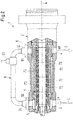
- Fig. 2 shows a cross-sectional view of a second embodiment of a multiphase pump 1 according to the invention.
- the second embodiment is designed as a horizontal pump 1.
- the multiphase pump 1 is designed as a multistage pump 1, wherein the pump rotor 7 comprises a plurality of impellers 72 arranged in series on the shaft 71.
- the impellers 72 are designed as semi-axial impellers 72. Between adjacent impellers 72 in each case a stationary diffusor 73 is provided for directing the process fluid to the next stage impeller 72.
- the drive unit 8 for rotating the pump rotor 7 is not shown in Fig. 2 .
- Fig. 3 shows a cross-sectional view of a third embodiment of a multiphase pump 1 according to the invention.
- the third embodiment is here designed as a vertical pump.
- the drive unit 8 for rotating the pump rotor 7 is not shown in Fig. 3 .
- the return line 9 is fixedly connected to the housing 2 in a non-detachable manner.
- the return line 9 is for example welded to the housing 2 as indicated by the welding seams 96 in Fig. 3 .
- Fig. 4 shows a cross-sectional view of a fourth embodiment of a multiphase pump 1 according to the invention.
- the fourth embodiment is here designed as a vertical pump.
- the drive unit 8 for rotating the pump rotor 7 is not shown in Fig. 4 .
- the return line 9 is an internal line, i.e. the return line 9 is arranged inside the housing 2 of the multiphase pump 1.
Landscapes
- Engineering & Computer Science (AREA)
- Mechanical Engineering (AREA)
- General Engineering & Computer Science (AREA)
- Life Sciences & Earth Sciences (AREA)
- Mining & Mineral Resources (AREA)
- Geology (AREA)
- Fluid Mechanics (AREA)
- Environmental & Geological Engineering (AREA)
- Physics & Mathematics (AREA)
- General Life Sciences & Earth Sciences (AREA)
- Geochemistry & Mineralogy (AREA)
- Sustainable Development (AREA)
- Structures Of Non-Positive Displacement Pumps (AREA)
- Details And Applications Of Rotary Liquid Pumps (AREA)
- Rotary Pumps (AREA)
Applications Claiming Priority (1)
| Application Number | Priority Date | Filing Date | Title |
|---|---|---|---|
| EP18194754 | 2018-09-17 |
Publications (2)
| Publication Number | Publication Date |
|---|---|
| EP3623633A1 true EP3623633A1 (fr) | 2020-03-18 |
| EP3623633B1 EP3623633B1 (fr) | 2022-11-02 |
Family
ID=63637706
Family Applications (1)
| Application Number | Title | Priority Date | Filing Date |
|---|---|---|---|
| EP19197704.0A Active EP3623633B1 (fr) | 2018-09-17 | 2019-09-17 | Pompe à phases multiples |
Country Status (8)
| Country | Link |
|---|---|
| US (1) | US12135044B2 (fr) |
| EP (1) | EP3623633B1 (fr) |
| KR (1) | KR20200032638A (fr) |
| CN (1) | CN110905863B (fr) |
| AU (1) | AU2019219857B2 (fr) |
| CA (1) | CA3052441A1 (fr) |
| RU (1) | RU2019127660A (fr) |
| SG (1) | SG10201907366PA (fr) |
Cited By (1)
| Publication number | Priority date | Publication date | Assignee | Title |
|---|---|---|---|---|
| CN119982629A (zh) * | 2025-03-31 | 2025-05-13 | 重庆水泵厂有限责任公司 | 低轴向力多层增压轴流叶轮的设计方法 |
Families Citing this family (5)
| Publication number | Priority date | Publication date | Assignee | Title |
|---|---|---|---|---|
| WO2020072053A1 (fr) * | 2018-10-03 | 2020-04-09 | Halliburton Energy Services, Inc. | Pompe électrique immergée à recyclage du refoulement |
| EP3913226A1 (fr) * | 2020-05-18 | 2021-11-24 | Sulzer Management AG | Pompe à phases multiples |
| CN112855614B (zh) * | 2021-01-31 | 2022-09-23 | 安徽南方化工泵业有限公司 | 一种智能离心水泵 |
| EP4116588A1 (fr) * | 2021-07-06 | 2023-01-11 | Sulzer Management AG | Pompe centrifuge à étages multiples avec un passage de recirculation |
| CN114233633A (zh) * | 2022-01-10 | 2022-03-25 | 浙江南元泵业有限公司 | 一种带有增压流道的卧式单级离心泵 |
Citations (4)
| Publication number | Priority date | Publication date | Assignee | Title |
|---|---|---|---|---|
| EP2626564A1 (fr) | 2012-02-10 | 2013-08-14 | Sulzer Pumpen Ag | Pompe, dispositif de séparation pour une pompe, ainsi qu'arbre de rotor pour une pompe |
| WO2016077674A1 (fr) * | 2014-11-13 | 2016-05-19 | General Electric Company | Système de traitement de fluide sous-marin avec recirculation intermédiaire |
| EP3037668A1 (fr) | 2014-12-18 | 2016-06-29 | Sulzer Management AG | Procede de fonctionnement d'une pompe, en particulier une pompe multiphases et pompe |
| US20180073509A1 (en) * | 2016-09-13 | 2018-03-15 | Grundfos Holding A/S | Centrifugal pump assembly |
Family Cites Families (14)
| Publication number | Priority date | Publication date | Assignee | Title |
|---|---|---|---|---|
| US3268155A (en) * | 1964-02-07 | 1966-08-23 | Ingersoll Rand Co | Fluid-flow control system |
| GB1184972A (en) * | 1968-01-02 | 1970-03-18 | Pegg S & Son Ltd | Reversible Impeller Pump |
| US6135723A (en) * | 1999-01-19 | 2000-10-24 | Hatton; Gregory John | Efficient Multistage pump |
| JP3475174B2 (ja) * | 2000-02-10 | 2003-12-08 | 東芝テック株式会社 | 電動ポンプ |
| DE50206223D1 (de) * | 2001-10-22 | 2006-05-18 | Sulzer Pumpen Ag | Wellenabdichtungsanordnung für eine Pumpe zur Förderung heisser Fluide |
| US20070177990A1 (en) * | 2006-01-27 | 2007-08-02 | Applied Drives & Systems, Inc. | Centrifugal pump casing relief system |
| CN101265914B (zh) * | 2008-05-12 | 2010-06-02 | 杭州小尔机电设计有限公司 | 两相流潜水泵疏浚系统中加压站最优数量的确定方法 |
| JP2010031808A (ja) * | 2008-07-30 | 2010-02-12 | Shinmaywa Industries Ltd | ポンプ用ケーシング及びそれを備えたポンプ |
| DE102012015064B4 (de) * | 2012-07-31 | 2018-08-02 | Joh. Heinr. Bornemann Gmbh | Verfahren zum Betreiben einer Multiphasenpumpe und Vorrichtung dazu |
| NO337108B1 (no) * | 2012-08-14 | 2016-01-25 | Aker Subsea As | Flerfase trykkforsterkningspumpe |
| CN102787817B (zh) | 2012-09-08 | 2015-02-18 | 东北石油大学 | 钻井循环系统综合模拟实验装置 |
| WO2014095291A1 (fr) * | 2012-12-20 | 2014-06-26 | Sulzer Pumpen Ag | Pompe polyphasique avec séparateur, avec lubrification et refroidissement de la pompe par le liquide de traitement |
| NO338575B1 (no) * | 2014-09-16 | 2016-09-05 | Fmc Kongsberg Subsea As | System for pumping av et fluid og fremgangsmåte for dens drift. |
| US10533578B2 (en) * | 2015-10-12 | 2020-01-14 | Baker Hughes, A Ge Company, Llc | Metal-to-metal sealing for diffusers of an electrical submersible well pump |
-
2019
- 2019-08-08 SG SG10201907366PA patent/SG10201907366PA/en unknown
- 2019-08-19 CA CA3052441A patent/CA3052441A1/fr active Pending
- 2019-08-23 AU AU2019219857A patent/AU2019219857B2/en active Active
- 2019-08-30 KR KR1020190107221A patent/KR20200032638A/ko not_active Withdrawn
- 2019-09-03 CN CN201910827382.8A patent/CN110905863B/zh active Active
- 2019-09-03 RU RU2019127660A patent/RU2019127660A/ru unknown
- 2019-09-03 US US16/558,953 patent/US12135044B2/en active Active
- 2019-09-17 EP EP19197704.0A patent/EP3623633B1/fr active Active
Patent Citations (5)
| Publication number | Priority date | Publication date | Assignee | Title |
|---|---|---|---|---|
| EP2626564A1 (fr) | 2012-02-10 | 2013-08-14 | Sulzer Pumpen Ag | Pompe, dispositif de séparation pour une pompe, ainsi qu'arbre de rotor pour une pompe |
| EP2626563A2 (fr) | 2012-02-10 | 2013-08-14 | Sulzer Pumpen Ag | Pompe, installation de recirculation pour une pompe et arbre de rotor pour une pompe |
| WO2016077674A1 (fr) * | 2014-11-13 | 2016-05-19 | General Electric Company | Système de traitement de fluide sous-marin avec recirculation intermédiaire |
| EP3037668A1 (fr) | 2014-12-18 | 2016-06-29 | Sulzer Management AG | Procede de fonctionnement d'une pompe, en particulier une pompe multiphases et pompe |
| US20180073509A1 (en) * | 2016-09-13 | 2018-03-15 | Grundfos Holding A/S | Centrifugal pump assembly |
Cited By (1)
| Publication number | Priority date | Publication date | Assignee | Title |
|---|---|---|---|---|
| CN119982629A (zh) * | 2025-03-31 | 2025-05-13 | 重庆水泵厂有限责任公司 | 低轴向力多层增压轴流叶轮的设计方法 |
Also Published As
| Publication number | Publication date |
|---|---|
| AU2019219857B2 (en) | 2024-08-15 |
| EP3623633B1 (fr) | 2022-11-02 |
| US12135044B2 (en) | 2024-11-05 |
| CN110905863B (zh) | 2023-07-07 |
| RU2019127660A (ru) | 2021-03-03 |
| US20200088201A1 (en) | 2020-03-19 |
| KR20200032638A (ko) | 2020-03-26 |
| AU2019219857A1 (en) | 2020-04-02 |
| BR102019017801A2 (pt) | 2020-03-31 |
| CN110905863A (zh) | 2020-03-24 |
| CA3052441A1 (fr) | 2020-03-17 |
| SG10201907366PA (en) | 2020-04-29 |
Similar Documents
| Publication | Publication Date | Title |
|---|---|---|
| EP3623633B1 (fr) | Pompe à phases multiples | |
| US6171074B1 (en) | Single-shaft compression-pumping device associated with a separator | |
| US9784075B2 (en) | Gas compression system | |
| US7569097B2 (en) | Subsea multiphase pumping systems | |
| US10330122B2 (en) | Operating method for a pump, in particular for a multiphase pump, and pump | |
| EP4031748B1 (fr) | Appareil et système d'amplification de tête de puits | |
| WO2018077527A1 (fr) | Pompe polyphasique et procédé de fonctionnement de ladite pompe | |
| EP3832140B1 (fr) | Procédé de fonctionnement d'une pompe, en particulier une pompe à phases multiples | |
| EP4063665B1 (fr) | Pompe à phases multiples | |
| AU2015202860B2 (en) | Combined multi-phase pump and compressor unit and gas compression system | |
| Cooper et al. | Multiphase gas-liquid pumping | |
| BR102019017801B1 (pt) | Bomba multifásica | |
| EP0554937B1 (fr) | Pompe à anneau liquide | |
| RU2834626C1 (ru) | Способ распределения потоков рабочих сред на подводной технологической установке | |
| Torp | Subsea Multiphase Boosting: Review and Future Applications |
Legal Events
| Date | Code | Title | Description |
|---|---|---|---|
| PUAI | Public reference made under article 153(3) epc to a published international application that has entered the european phase |
Free format text: ORIGINAL CODE: 0009012 |
|
| STAA | Information on the status of an ep patent application or granted ep patent |
Free format text: STATUS: THE APPLICATION HAS BEEN PUBLISHED |
|
| AK | Designated contracting states |
Kind code of ref document: A1 Designated state(s): AL AT BE BG CH CY CZ DE DK EE ES FI FR GB GR HR HU IE IS IT LI LT LU LV MC MK MT NL NO PL PT RO RS SE SI SK SM TR |
|
| STAA | Information on the status of an ep patent application or granted ep patent |
Free format text: STATUS: REQUEST FOR EXAMINATION WAS MADE |
|
| 17P | Request for examination filed |
Effective date: 20200918 |
|
| RBV | Designated contracting states (corrected) |
Designated state(s): AL AT BE BG CH CY CZ DE DK EE ES FI FR GB GR HR HU IE IS IT LI LT LU LV MC MK MT NL NO PL PT RO RS SE SI SK SM TR |
|
| GRAP | Despatch of communication of intention to grant a patent |
Free format text: ORIGINAL CODE: EPIDOSNIGR1 |
|
| STAA | Information on the status of an ep patent application or granted ep patent |
Free format text: STATUS: GRANT OF PATENT IS INTENDED |
|
| INTG | Intention to grant announced |
Effective date: 20220504 |
|
| GRAS | Grant fee paid |
Free format text: ORIGINAL CODE: EPIDOSNIGR3 |
|
| GRAA | (expected) grant |
Free format text: ORIGINAL CODE: 0009210 |
|
| STAA | Information on the status of an ep patent application or granted ep patent |
Free format text: STATUS: THE PATENT HAS BEEN GRANTED |
|
| AK | Designated contracting states |
Kind code of ref document: B1 Designated state(s): AL AT BE BG CH CY CZ DE DK EE ES FI FR GB GR HR HU IE IS IT LI LT LU LV MC MK MT NL NO PL PT RO RS SE SI SK SM TR |
|
| REG | Reference to a national code |
Ref country code: GB Ref legal event code: FG4D |
|
| REG | Reference to a national code |
Ref country code: CH Ref legal event code: EP Ref country code: AT Ref legal event code: REF Ref document number: 1528935 Country of ref document: AT Kind code of ref document: T Effective date: 20221115 |
|
| REG | Reference to a national code |
Ref country code: DE Ref legal event code: R096 Ref document number: 602019021361 Country of ref document: DE |
|
| REG | Reference to a national code |
Ref country code: IE Ref legal event code: FG4D |
|
| REG | Reference to a national code |
Ref country code: NO Ref legal event code: T2 Effective date: 20221102 |
|
| REG | Reference to a national code |
Ref country code: LT Ref legal event code: MG9D |
|
| REG | Reference to a national code |
Ref country code: NL Ref legal event code: MP Effective date: 20221102 |
|
| REG | Reference to a national code |
Ref country code: AT Ref legal event code: MK05 Ref document number: 1528935 Country of ref document: AT Kind code of ref document: T Effective date: 20221102 |
|
| PG25 | Lapsed in a contracting state [announced via postgrant information from national office to epo] |
Ref country code: SE Free format text: LAPSE BECAUSE OF FAILURE TO SUBMIT A TRANSLATION OF THE DESCRIPTION OR TO PAY THE FEE WITHIN THE PRESCRIBED TIME-LIMIT Effective date: 20221102 Ref country code: PT Free format text: LAPSE BECAUSE OF FAILURE TO SUBMIT A TRANSLATION OF THE DESCRIPTION OR TO PAY THE FEE WITHIN THE PRESCRIBED TIME-LIMIT Effective date: 20230302 Ref country code: LT Free format text: LAPSE BECAUSE OF FAILURE TO SUBMIT A TRANSLATION OF THE DESCRIPTION OR TO PAY THE FEE WITHIN THE PRESCRIBED TIME-LIMIT Effective date: 20221102 Ref country code: FI Free format text: LAPSE BECAUSE OF FAILURE TO SUBMIT A TRANSLATION OF THE DESCRIPTION OR TO PAY THE FEE WITHIN THE PRESCRIBED TIME-LIMIT Effective date: 20221102 Ref country code: ES Free format text: LAPSE BECAUSE OF FAILURE TO SUBMIT A TRANSLATION OF THE DESCRIPTION OR TO PAY THE FEE WITHIN THE PRESCRIBED TIME-LIMIT Effective date: 20221102 Ref country code: AT Free format text: LAPSE BECAUSE OF FAILURE TO SUBMIT A TRANSLATION OF THE DESCRIPTION OR TO PAY THE FEE WITHIN THE PRESCRIBED TIME-LIMIT Effective date: 20221102 |
|
| PG25 | Lapsed in a contracting state [announced via postgrant information from national office to epo] |
Ref country code: RS Free format text: LAPSE BECAUSE OF FAILURE TO SUBMIT A TRANSLATION OF THE DESCRIPTION OR TO PAY THE FEE WITHIN THE PRESCRIBED TIME-LIMIT Effective date: 20221102 Ref country code: PL Free format text: LAPSE BECAUSE OF FAILURE TO SUBMIT A TRANSLATION OF THE DESCRIPTION OR TO PAY THE FEE WITHIN THE PRESCRIBED TIME-LIMIT Effective date: 20221102 Ref country code: LV Free format text: LAPSE BECAUSE OF FAILURE TO SUBMIT A TRANSLATION OF THE DESCRIPTION OR TO PAY THE FEE WITHIN THE PRESCRIBED TIME-LIMIT Effective date: 20221102 Ref country code: IS Free format text: LAPSE BECAUSE OF FAILURE TO SUBMIT A TRANSLATION OF THE DESCRIPTION OR TO PAY THE FEE WITHIN THE PRESCRIBED TIME-LIMIT Effective date: 20230302 Ref country code: HR Free format text: LAPSE BECAUSE OF FAILURE TO SUBMIT A TRANSLATION OF THE DESCRIPTION OR TO PAY THE FEE WITHIN THE PRESCRIBED TIME-LIMIT Effective date: 20221102 Ref country code: GR Free format text: LAPSE BECAUSE OF FAILURE TO SUBMIT A TRANSLATION OF THE DESCRIPTION OR TO PAY THE FEE WITHIN THE PRESCRIBED TIME-LIMIT Effective date: 20230203 |
|
| P01 | Opt-out of the competence of the unified patent court (upc) registered |
Effective date: 20230412 |
|
| PG25 | Lapsed in a contracting state [announced via postgrant information from national office to epo] |
Ref country code: NL Free format text: LAPSE BECAUSE OF FAILURE TO SUBMIT A TRANSLATION OF THE DESCRIPTION OR TO PAY THE FEE WITHIN THE PRESCRIBED TIME-LIMIT Effective date: 20221102 |
|
| PG25 | Lapsed in a contracting state [announced via postgrant information from national office to epo] |
Ref country code: SM Free format text: LAPSE BECAUSE OF FAILURE TO SUBMIT A TRANSLATION OF THE DESCRIPTION OR TO PAY THE FEE WITHIN THE PRESCRIBED TIME-LIMIT Effective date: 20221102 Ref country code: RO Free format text: LAPSE BECAUSE OF FAILURE TO SUBMIT A TRANSLATION OF THE DESCRIPTION OR TO PAY THE FEE WITHIN THE PRESCRIBED TIME-LIMIT Effective date: 20221102 Ref country code: EE Free format text: LAPSE BECAUSE OF FAILURE TO SUBMIT A TRANSLATION OF THE DESCRIPTION OR TO PAY THE FEE WITHIN THE PRESCRIBED TIME-LIMIT Effective date: 20221102 Ref country code: DK Free format text: LAPSE BECAUSE OF FAILURE TO SUBMIT A TRANSLATION OF THE DESCRIPTION OR TO PAY THE FEE WITHIN THE PRESCRIBED TIME-LIMIT Effective date: 20221102 Ref country code: CZ Free format text: LAPSE BECAUSE OF FAILURE TO SUBMIT A TRANSLATION OF THE DESCRIPTION OR TO PAY THE FEE WITHIN THE PRESCRIBED TIME-LIMIT Effective date: 20221102 |
|
| REG | Reference to a national code |
Ref country code: DE Ref legal event code: R097 Ref document number: 602019021361 Country of ref document: DE |
|
| PG25 | Lapsed in a contracting state [announced via postgrant information from national office to epo] |
Ref country code: SK Free format text: LAPSE BECAUSE OF FAILURE TO SUBMIT A TRANSLATION OF THE DESCRIPTION OR TO PAY THE FEE WITHIN THE PRESCRIBED TIME-LIMIT Effective date: 20221102 Ref country code: AL Free format text: LAPSE BECAUSE OF FAILURE TO SUBMIT A TRANSLATION OF THE DESCRIPTION OR TO PAY THE FEE WITHIN THE PRESCRIBED TIME-LIMIT Effective date: 20221102 |
|
| PLBE | No opposition filed within time limit |
Free format text: ORIGINAL CODE: 0009261 |
|
| STAA | Information on the status of an ep patent application or granted ep patent |
Free format text: STATUS: NO OPPOSITION FILED WITHIN TIME LIMIT |
|
| 26N | No opposition filed |
Effective date: 20230803 |
|
| PG25 | Lapsed in a contracting state [announced via postgrant information from national office to epo] |
Ref country code: SI Free format text: LAPSE BECAUSE OF FAILURE TO SUBMIT A TRANSLATION OF THE DESCRIPTION OR TO PAY THE FEE WITHIN THE PRESCRIBED TIME-LIMIT Effective date: 20221102 |
|
| REG | Reference to a national code |
Ref country code: CH Ref legal event code: PL |
|
| PG25 | Lapsed in a contracting state [announced via postgrant information from national office to epo] |
Ref country code: LU Free format text: LAPSE BECAUSE OF NON-PAYMENT OF DUE FEES Effective date: 20230917 |
|
| REG | Reference to a national code |
Ref country code: BE Ref legal event code: MM Effective date: 20230930 |
|
| PG25 | Lapsed in a contracting state [announced via postgrant information from national office to epo] |
Ref country code: LU Free format text: LAPSE BECAUSE OF NON-PAYMENT OF DUE FEES Effective date: 20230917 Ref country code: IT Free format text: LAPSE BECAUSE OF FAILURE TO SUBMIT A TRANSLATION OF THE DESCRIPTION OR TO PAY THE FEE WITHIN THE PRESCRIBED TIME-LIMIT Effective date: 20221102 Ref country code: MC Free format text: LAPSE BECAUSE OF FAILURE TO SUBMIT A TRANSLATION OF THE DESCRIPTION OR TO PAY THE FEE WITHIN THE PRESCRIBED TIME-LIMIT Effective date: 20221102 |
|
| REG | Reference to a national code |
Ref country code: IE Ref legal event code: MM4A |
|
| PG25 | Lapsed in a contracting state [announced via postgrant information from national office to epo] |
Ref country code: IE Free format text: LAPSE BECAUSE OF NON-PAYMENT OF DUE FEES Effective date: 20230917 |
|
| PG25 | Lapsed in a contracting state [announced via postgrant information from national office to epo] |
Ref country code: CH Free format text: LAPSE BECAUSE OF NON-PAYMENT OF DUE FEES Effective date: 20230930 |
|
| PG25 | Lapsed in a contracting state [announced via postgrant information from national office to epo] |
Ref country code: IE Free format text: LAPSE BECAUSE OF NON-PAYMENT OF DUE FEES Effective date: 20230917 Ref country code: CH Free format text: LAPSE BECAUSE OF NON-PAYMENT OF DUE FEES Effective date: 20230930 |
|
| PG25 | Lapsed in a contracting state [announced via postgrant information from national office to epo] |
Ref country code: BE Free format text: LAPSE BECAUSE OF NON-PAYMENT OF DUE FEES Effective date: 20230930 |
|
| PG25 | Lapsed in a contracting state [announced via postgrant information from national office to epo] |
Ref country code: BG Free format text: LAPSE BECAUSE OF FAILURE TO SUBMIT A TRANSLATION OF THE DESCRIPTION OR TO PAY THE FEE WITHIN THE PRESCRIBED TIME-LIMIT Effective date: 20221102 |
|
| PG25 | Lapsed in a contracting state [announced via postgrant information from national office to epo] |
Ref country code: BG Free format text: LAPSE BECAUSE OF FAILURE TO SUBMIT A TRANSLATION OF THE DESCRIPTION OR TO PAY THE FEE WITHIN THE PRESCRIBED TIME-LIMIT Effective date: 20221102 |
|
| PG25 | Lapsed in a contracting state [announced via postgrant information from national office to epo] |
Ref country code: CY Free format text: LAPSE BECAUSE OF FAILURE TO SUBMIT A TRANSLATION OF THE DESCRIPTION OR TO PAY THE FEE WITHIN THE PRESCRIBED TIME-LIMIT; INVALID AB INITIO Effective date: 20190917 |
|
| PG25 | Lapsed in a contracting state [announced via postgrant information from national office to epo] |
Ref country code: HU Free format text: LAPSE BECAUSE OF FAILURE TO SUBMIT A TRANSLATION OF THE DESCRIPTION OR TO PAY THE FEE WITHIN THE PRESCRIBED TIME-LIMIT; INVALID AB INITIO Effective date: 20190917 |
|
| PGFP | Annual fee paid to national office [announced via postgrant information from national office to epo] |
Ref country code: DE Payment date: 20250919 Year of fee payment: 7 |
|
| PGFP | Annual fee paid to national office [announced via postgrant information from national office to epo] |
Ref country code: NO Payment date: 20250923 Year of fee payment: 7 |
|
| PGFP | Annual fee paid to national office [announced via postgrant information from national office to epo] |
Ref country code: GB Payment date: 20250919 Year of fee payment: 7 |
|
| PGFP | Annual fee paid to national office [announced via postgrant information from national office to epo] |
Ref country code: FR Payment date: 20250922 Year of fee payment: 7 |
|
| PG25 | Lapsed in a contracting state [announced via postgrant information from national office to epo] |
Ref country code: TR Free format text: LAPSE BECAUSE OF FAILURE TO SUBMIT A TRANSLATION OF THE DESCRIPTION OR TO PAY THE FEE WITHIN THE PRESCRIBED TIME-LIMIT Effective date: 20221102 |