EP2628499B1 - Drainagekatheter - Google Patents
Drainagekatheter Download PDFInfo
- Publication number
- EP2628499B1 EP2628499B1 EP13168109.0A EP13168109A EP2628499B1 EP 2628499 B1 EP2628499 B1 EP 2628499B1 EP 13168109 A EP13168109 A EP 13168109A EP 2628499 B1 EP2628499 B1 EP 2628499B1
- Authority
- EP
- European Patent Office
- Prior art keywords
- catheter
- lumen
- shaft
- abutting member
- outer diameter
- Prior art date
- Legal status (The legal status is an assumption and is not a legal conclusion. Google has not performed a legal analysis and makes no representation as to the accuracy of the status listed.)
- Not-in-force
Links
- 239000000463 material Substances 0.000 claims description 39
- 230000007704 transition Effects 0.000 claims description 23
- 238000000034 method Methods 0.000 description 11
- 239000012530 fluid Substances 0.000 description 9
- 238000003780 insertion Methods 0.000 description 6
- 230000037431 insertion Effects 0.000 description 6
- 210000000683 abdominal cavity Anatomy 0.000 description 3
- 239000000853 adhesive Substances 0.000 description 2
- 230000001070 adhesive effect Effects 0.000 description 2
- 238000010276 construction Methods 0.000 description 2
- 238000000502 dialysis Methods 0.000 description 2
- 239000003550 marker Substances 0.000 description 2
- 230000013011 mating Effects 0.000 description 2
- 238000005192 partition Methods 0.000 description 2
- 229920002635 polyurethane Polymers 0.000 description 2
- 239000004814 polyurethane Substances 0.000 description 2
- 239000002904 solvent Substances 0.000 description 2
- 239000004677 Nylon Substances 0.000 description 1
- 239000004433 Thermoplastic polyurethane Substances 0.000 description 1
- 206010000269 abscess Diseases 0.000 description 1
- 239000004676 acrylonitrile butadiene styrene Substances 0.000 description 1
- XAGFODPZIPBFFR-UHFFFAOYSA-N aluminium Chemical compound [Al] XAGFODPZIPBFFR-UHFFFAOYSA-N 0.000 description 1
- 229910052782 aluminium Inorganic materials 0.000 description 1
- 239000004599 antimicrobial Substances 0.000 description 1
- 238000000576 coating method Methods 0.000 description 1
- 230000001419 dependent effect Effects 0.000 description 1
- 239000005038 ethylene vinyl acetate Substances 0.000 description 1
- 239000000945 filler Substances 0.000 description 1
- 230000004927 fusion Effects 0.000 description 1
- 238000004519 manufacturing process Methods 0.000 description 1
- 238000012986 modification Methods 0.000 description 1
- 230000004048 modification Effects 0.000 description 1
- 238000000465 moulding Methods 0.000 description 1
- 229920001778 nylon Polymers 0.000 description 1
- 210000000056 organ Anatomy 0.000 description 1
- 229920003023 plastic Polymers 0.000 description 1
- 239000004033 plastic Substances 0.000 description 1
- 239000004417 polycarbonate Substances 0.000 description 1
- 229920000515 polycarbonate Polymers 0.000 description 1
- 229920001296 polysiloxane Polymers 0.000 description 1
- 239000004800 polyvinyl chloride Substances 0.000 description 1
- 239000007779 soft material Substances 0.000 description 1
- 239000000126 substance Substances 0.000 description 1
- 229920002803 thermoplastic polyurethane Polymers 0.000 description 1
- 230000002792 vascular Effects 0.000 description 1
Images



Classifications
-
- A—HUMAN NECESSITIES
- A61—MEDICAL OR VETERINARY SCIENCE; HYGIENE
- A61M—DEVICES FOR INTRODUCING MEDIA INTO, OR ONTO, THE BODY; DEVICES FOR TRANSDUCING BODY MEDIA OR FOR TAKING MEDIA FROM THE BODY; DEVICES FOR PRODUCING OR ENDING SLEEP OR STUPOR
- A61M25/00—Catheters; Hollow probes
- A61M25/0067—Catheters; Hollow probes characterised by the distal end, e.g. tips
- A61M25/0068—Static characteristics of the catheter tip, e.g. shape, atraumatic tip, curved tip or tip structure
- A61M25/0069—Tip not integral with tube
-
- A—HUMAN NECESSITIES
- A61—MEDICAL OR VETERINARY SCIENCE; HYGIENE
- A61M—DEVICES FOR INTRODUCING MEDIA INTO, OR ONTO, THE BODY; DEVICES FOR TRANSDUCING BODY MEDIA OR FOR TAKING MEDIA FROM THE BODY; DEVICES FOR PRODUCING OR ENDING SLEEP OR STUPOR
- A61M25/00—Catheters; Hollow probes
- A61M25/0043—Catheters; Hollow probes characterised by structural features
- A61M25/005—Catheters; Hollow probes characterised by structural features with embedded materials for reinforcement, e.g. wires, coils, braids
-
- A—HUMAN NECESSITIES
- A61—MEDICAL OR VETERINARY SCIENCE; HYGIENE
- A61M—DEVICES FOR INTRODUCING MEDIA INTO, OR ONTO, THE BODY; DEVICES FOR TRANSDUCING BODY MEDIA OR FOR TAKING MEDIA FROM THE BODY; DEVICES FOR PRODUCING OR ENDING SLEEP OR STUPOR
- A61M25/00—Catheters; Hollow probes
- A61M25/0043—Catheters; Hollow probes characterised by structural features
- A61M2025/0063—Catheters; Hollow probes characterised by structural features having means, e.g. stylets, mandrils, rods or wires to reinforce or adjust temporarily the stiffness, column strength or pushability of catheters which are already inserted into the human body
-
- A—HUMAN NECESSITIES
- A61—MEDICAL OR VETERINARY SCIENCE; HYGIENE
- A61M—DEVICES FOR INTRODUCING MEDIA INTO, OR ONTO, THE BODY; DEVICES FOR TRANSDUCING BODY MEDIA OR FOR TAKING MEDIA FROM THE BODY; DEVICES FOR PRODUCING OR ENDING SLEEP OR STUPOR
- A61M27/00—Drainage appliance for wounds or the like, i.e. wound drains, implanted drains
Definitions
- Drainage catheters are often inserted percutaneously into abscesses or other structures to drain fluids.
- the shafts of these catheters are formed in a variety of sizes, durometers, and coatings. Holes located at the distal end of a typical drainage catheter allow fluids surrounding the catheter to enter a lumen through which they flow to the proximal end of the catheter out of the body.
- these catheters are generally made of soft biocompatible plastic. The soft material generally results in low column strength, so that a stiffening member is often inserted into a drainage catheter to allow it to be pushed into the body to a desired location. The stiffening member often abuts a surface near the distal end of the lumen at which the lumen tapers or steps down from a larger diameter, proximal portion to a reduced diameter, distal portion.
- US 2002/0091352 A1 discloses a peritoneal dialysis catheter for insertion into the abdominal cavity of a patient for delivering and withdrawing fluid from a patient comprising a catheter body having a proximal portion, a distal tip portion and a first longitudinally extending lumen configured to deliver fluid into the abdominal cavity.
- a stiffening insert is portioned in the distal tip portion and has a first stiffness greater than a second stiffness of the distal tip portion to facilitate entry into the abdominal cavity.
- the stiffening insert has a lumen therethrough communicating with the first lumen.
- US 2003/0153873 A1 shows a catheter comprising a soft flexible tube and a discrete segment of hard tubing that is press fit into the interior of the distal end of the soft tube.
- US 2006/0258982 A1 describes a catheter tip assembly comprising a marker band and a catheter tip.
- the catheter tip has an inner lumen therethrough and an outer portion and an inner portion with the marker band disposed therebetween.
- the outer tip portion and the inner tip portion can be made of different materials.
- the present invention is directed to a catheter as defined in independent claim 1 and appended dependent claims.
- the present invention may be further understood with reference to the following description and the appended drawings, wherein like elements are referred to with the same reference numerals.
- the invention relates to devices for draining fluid from the body. More specifically, the invention relates to a novel construction for a drainage catheter.
- Drainage catheters typically are made of either a single material, or with a tip section separate from the catheter shaft.
- the separate tip section may be made of either a material with a different durometer than the catheter shaft, or a different material altogether.
- stiffening members are often inserted into drainage catheters to aid in insertion.
- frictional drag along the outside of the catheter body may result in stretching of the catheter and/or the deformation of the material at the end of the lumen contacted by the stiffening member.
- the stiffening member may become lodged within the tip section, preventing the removal of the stiffening member from the catheter. In such cases, the entire catheter must be removed and replaced, increasing discomfort and the time required for the procedure.
- the catheter according to the present invention includes an abutting structure within the distal end of the lumen formed of a material having a higher durometer than that of the material of which the rest of the catheter is formed.
- the increased durometer of the abutting structure reduces the likelihood of the stiffening member becoming stuck within the tip section.
- the abutting structure is preferably formed of material of a higher modulus of elasticity than the material of which a shaft of the catheter is formed and may, more preferably be a dissolvable material as described in U.S. Patents 5,401,257 and 5,049,138 .
- the abutting structure according to the embodiments of this invention may be fused to the catheter shaft material within the tip section as part of the tipping process by, for example, mechanical bonding (e.g., press fit, or snap fit) and/or chemical bonding (e.g., heat fusion, adhesives, or solvents).
- mechanical bonding e.g., press fit, or snap fit
- chemical bonding e.g., heat fusion, adhesives, or solvents
- the abutting structure may be added to the catheter shaft material in a process other than the tipping process.
- These alternative processes may include a separate adhesive process, a solvent bonding process, a mechanical fit process, or an over-molding process.
- An outer diameter of the abutting structure preferably mates with an inner diameter of a portion of the catheter shaft within which it is to reside while an inner diameter of the abutting structure is preferably substantially a desired inner diameter of a portion of the lumen extending through the tip section so that the abutting structure does not interfere with fluid flow through the lumen.
- a drainage catheter assembly 10 includes a lumen 11 extending through a shaft 12 from the distal end to the proximal end thereof.
- multiple holes 14 near the distal end of the catheter shaft 12 allow fluids to drain out of the body.
- the tip section 16 of the catheter shaft 12 may have a curled, 'pigtail' shape which anchors the drainage catheter assembly 10 at the outlet from the organ chamber to a lumen through which the catheter assembly 10 was introduced thereinto.
- tip 16 including an abutting structure 60 forms a stepped transition 20 in the ,lumen 11.
- the abutting structure 60 is formed as a ring mounted within the lumen 11 with the abutting structure 60 being formed of a material stiffer than the material of which the rest of the catheter 10 is formed.
- An outer diameter of the abutting structure 60 is substantially equal to an inner diameter of the lumen 11 to mate with the inner surface of the catheter shaft 12.
- the abutting structure 60 extends through the entire tip section 16 to end at the distal opening of the catheter 10.
- the inner diameter of the abutting structure 60 defines a narrower inner diameter lumen portion 11' of the lumen 11 extending through the tip section 16.
- a proximal end of the abutting structure 60 defines an increased stiffness stepped transition 20' within the lumen portion 11'.
- a material of the stepped transition 20 is less likely to deform, thus reducing the likelihood of the stiffening member becoming lodged within the tip section 16, as those skilled in the art will understand.
- the catheter 10 and, the abutting structure 60 may be formed of one of the same material and different materials.
- the materials for either one may include, for example, any type of thermoplastic polyurethane or low density polyurethane, silicone, ethylene vinyl acetate (EVA), or polyvinyl chloride (PVC), etc.
- the materials may also include a filler such as, for example, a radiopacifier or ⁇ anti-microbial agent.
- the abutting structure may each have a different hardness depending on the material chosen. If a material of the abutting structure 60 is the same as that of the catheter 10, it may only need to be of higher durometer than that of the shaft 12 in order to function as indicated above.
- the abutting surface may be formed of high density pollethylene (HDPE), nylon, polycarbonate, acrylonitrile butadiene styrene (ABS) and aluminum. Catheters made 6fthermoplastic polyurethane are commonly found in the durometer range of Shore 72A -Shore 84D, as would be understood by those skilled in the art.
- a tip 16 including an abutting structure 70 is mounted distally of a tapered tip section 72 of the lumen 11.
- the abutting structure 70 is formed as a ring of a material stiffer than that of which the rest of the catheter 10 is formed and is mated within the reduced diameter lumen portion 11'.
- the tapered tip section 72 reduces the diameter of lumen 11 in a distal direction and the abutting structure 70 forms a further stepped reduction in this diameter.
- the abutting structure 70 extends through the tip 16 from the distal end of the tapered tip section 72 to the distal end of the catheter 10.
- the outer diameter of the abutting structure 70 is substantially equal to the inner diameter of the lumen portion 11' (i. e., less than this inner diameter of the distal portion of the lumen 11 by only a tolerance amount necessary to facilitate insertion therein).
- the portion of the lumen 11 extending through the abutting structure 70 may have a substantially constant diameter along its length.
- the lumen portion 11' extending through the abutting structure 70 may comprise a tapered diameter.
- the tapered tip section 72 may extend along all or apart of the length of the abutting structure 70 with a corresponding taper on an outer surface of the abutting structure 70. As described above, the abutting structure 70 increases the stiffness of the tapered tip section 72 to reduce the likelihood that of a stiffening member being lodged within the tip section 16 or plastically deforming the tip section 16.
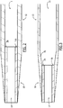
- an abutting structure 80 is formed at a proximal end of the tip 16.
- the abutting structure 80 is formed as a ring of higher stiffness material at a point where the catheter shaft 12 is joined to the, tip section 16.
- the abutting structure 80 may be formed with any desired width w (e.g., widths w4, w5, or w6), depending on the requirement of a procedure to be performed therewith.
- the outer diameter of the proximal end of the abutting structure 80 matches the outer diameter of the distal end of the catheter shaft 12 to form a continuous, smooth transition from the catheter shaft 12 to the tip 16.
- the outer diameter of the distal end of the abutting structure 80 matches the outer diameter of the proximal end of the tip section 16, to ⁇ also form a smooth transition therewith.
- the inner diameter of the abutting structure 80 is approximately equal to an inner diameter of the lumen portion 11' extending through the tip section 16. In this manner, the proximal end of the abutting surface 80 forms an increased stiffness stepped transition 20' to the lumen portion 11'.
- the abutting surface 80 reduces the likelihood that the stiffening member will become lodged within the tip section 16.
- an abutting structure 90 is formed at a proximal end of the tip 16.
- the abutting structure 90 is formed of a relatively stiff material in the shape of a ring joining a tapered transition 30 of the catheter shaft 12 to the tip section 16. Similar to the embodiment of Fig. 4 described above, the abutting structure 90 may have any desired width w (e.g., widths w4, wS, w6, etc.) depending on the desired characteristics of the tip 16.
- the outer diameter of a proximal end of the abutting structure 90 is substantially equal to that of the distal end of the tapered transition 30 of the catheter body 12 to form a smooth transition therebetween.
- any profile of each of the distal end of the catheter body 12, the abutting structure 90 and the tip 16 may be selected to achieve a desired overall contour of the distal end of the catheter 10 so long as transitions between these parts are smooth.
- the inner diameter of the abutting structure 90 is approximately equal to an inner diameter of the lumen portion 11' extending through the tip section 16.
- a proximal face 92 of the abutting structure 90 forms a stepped transition 94 at an interface with the shaft 12.
- the stiffness of the stepped transition 94 is also increased.
- the proximal face 92 of the abutting structure 90 reduces the likelihood that the stiffening member will become lodged within the tip section 16.
- an abutting structure 100 is formed as a liner of shell within the lumen portion 11' of the tip 16.
- the abutting structure 100 is formed of a material of increased stiffness relative to the material of which the catheter 10 is formed and extends along a tapered transition 30 of the tip 16.
- An outer diameter of the abutting structure 100 mates with an inner diameter of the tapered transition 30 with a tapered proximal thickness to create a smooth inner surface transition from the lumen 11 to the lumen portion 11', as those skilled in the art will understand.
- the abutting structure 100 further comprises a locating feature 102 which locks in a mating recess 104 formed within an inner diameter of the tip section 16 adjacent a distal end of the tapered transition 30.
- the abutting structure 100 assumes a locked configuration relative to the tip section 16, thereby increasing the stiffness of the tapered transition 30 and forming a hard shell around the tapered portion of the lumen portion 11'.
- Fig. 7 shows an abutting structure 200 formed at a proximal end of the tip 16 of a shaft 12 of a multilumen catheter.
- the abutting structure 200 is also formed as a ring of a higher stiffness material relative to the catheter shaft 12 and is situated adjacent a joint between the catheter shaft 12 and the tip 16.
- the abutting structure 200 extends across the distal end of the lumen 11, past a partition dividing the lumen 11 from a second lumen 13 and abuts a portion of the wall of the lumen 13 formed by an outer wall of the shaft 12.
- the abutting structure 200 is located proximally of the tapered tip section 16.
- the abutting structure 200 further comprises a first lumen 211 extending therethrough and substantially aligning with the lumen 11 so that, when the abutting structure is positioned as noted above, the lumen 211 connects the lumen 11 to the lumen 11'.
- a lumen 213 extending through the abutting structure 200 further aligns with the lumen 13, connecting the lumen 13 to a lumen 13' extending through the tip 16.
- the lumens 13, 213 and 13' open to the distal end of the tip 16 and may be used, for example, to provide aspiration, supply fluids, etc.
- the lumens 11, 211 and 11' may then be used for drainage as described above.
- Fig. 8 shows an abutting structure 300 wherein the abutting structure 300 is formed as a ring at a distal end of the catheter shaft 12. Similar to the previously described examples, the abutting structure 300 is formed as a ring of a higher stiffness material located between the catheter shaft 12 and the tip 16. The abutting structure 300 extends across the distal end of the inner diameter of the lumen 11, through a partition dividing the lumen 11 from the lumen 13 to abut a portion of the wall of the lumen 13 formed by an outer wall of the shaft 12. In this embodiment, the abutting structure 300 is located proximally of the tapered tip section 16.
- the abutting structure 300 comprises a lumen 311 extending therethrough substantially aligning with the lumen 11 to connect the lumen 11 to the lumen 11' of the tip 16, thus providing a stepped diameter from the lumen 11 to the lumen 11'.
- a portion of the abutting structure 300 extends across and closes a distal end of the lumen 13.
- the catheter shaft 12 further comprises an inflation port 313 connecting the lumen 13 to an exterior of the shaft 12 which is enveloped in a balloon 318.
- the provision of inflation fluid to the lumen 13 inflates the balloon 318 to, for example, abut adjacent tissue and lock the catheter in position.
- the abutting structures of the catheters according to the embodiments of the present invention and examples are shown in the appended figures as rings which substantially match the internal shape of the lumen of the catheter.
- rings which substantially match the internal shape of the lumen of the catheter.
- alternative designs other than rings e.g., projections into the lumen
- These shapes preferably conform to the shape of the lumen of a single lumen catheter.
- the shape of an abutting surface may conform to a shape of an outer wall of the catheter, to the shapes of the lumens themselves or may simply form projections into the lumens against which the stiffening member(s) will push.
- the abutting structures may be a variety of sizes (e.g., widths, thicknesses, or diameters) for use in a variety of catheters, for extra stiffening capacity, or for ease of manufacture. Further, one or more abutting structures may be added to multi-lumen drainage catheters as well.
- a stiffer material to a catheter shaft may also be used for other products (e.g., venous access catheters such as dialysis, tunneled central, and PICC (peripherally inserted central catheters)) that have flexible shafts into which an insertion tool or other device is inserted to impart a force to the product through contact with an internal structure which might be damaged if not formed of a material more stiff than that of which the rest of the catheter is formed.
- a construction may be employed for pacemaker leads, aneurism coils, removable core guidewires, introducer sheaths for vascular access, etc.
- the secondary material may be added along the entire length of the shaft or only along any portion of the shaft as desired, such as the tip section as shown in the exemplary embodiments.
Landscapes
- Health & Medical Sciences (AREA)
- Life Sciences & Earth Sciences (AREA)
- Biophysics (AREA)
- Pulmonology (AREA)
- Engineering & Computer Science (AREA)
- Anesthesiology (AREA)
- Biomedical Technology (AREA)
- Heart & Thoracic Surgery (AREA)
- Hematology (AREA)
- Animal Behavior & Ethology (AREA)
- General Health & Medical Sciences (AREA)
- Public Health (AREA)
- Veterinary Medicine (AREA)
- Media Introduction/Drainage Providing Device (AREA)
Claims (13)
- Katheter (10), der aufweist:einen Schaft (12), der aus einem ersten Material gebildet ist, wobei der Schaft (12) ein sich dadurch erstreckendes Schaftlumen (11) definiert;eine distale Spitze (16) mit einem sich dadurch erstreckenden Spitzenlumen (11') und einem Versteifungsteil,dadurch gekennzeichnet, dassdas Versteifungsteil ein Anlageteil (80, 90) ist, das aus einem zweiten Material gebildet ist, das steifer als das erste Material ist, wobei das Anlageteil (80, 90) ein sich dadurch erstreckendes Anlageteillumen (11') definiert, ein proximales Ende des Anlageteils (80, 90) mit einem distalen Ende des Schafts (12) gekoppelt ist, eine proximale Fläche des Anlageteils (80, 90) eine Anlagefläche bildet, die mindestens teilweise das Schaftlumen (11) abdeckt, ein Außendurchmesser des proximalen Endes des Anlageteils (80, 90) einem Außendurchmesser des distalen Endes des Schafts (12) entspricht; und ein proximales Ende der distalen Spitze (16) mit einem distalen Ende des Anlageteils (80, 90) gekoppelt ist, ein Außendurchmesser des proximalen Endes der distalen Spitze (16) dem Außendurchmesser des distalen Endes des Anlageteils (80, 90) entspricht und ein Innendurchmesser des Anlageteillumens (11') einem Innendurchmesser des proximalen Endes der distalen Spitze (16) entspricht.
- Katheter nach Anspruch 1, wobei der Innendurchmesser des Anlageteils (80, 90) kleiner als ein Innendurchmesser des Schafts (12) ist.
- Katheter nach Anspruch 1, wobei die distale Spitze (16) aus dem ersten Material gebildet ist.
- Katheter nach Anspruch 1, wobei die distale Spitze (16) aus einem dritten Material gebildet ist, wobei das erste Material steifer als das dritte Material ist.
- Katheter nach Anspruch 1, wobei der Innendurchmesser des Anlageteils (80, 90) über dessen Länge konstant ist.
- Katheter nach Anspruch 1, wobei sich der Innendurchmesser der distalen Spitze (16) durch eine Länge der distalen Spitze (16) erstreckt.
- Katheter nach Anspruch 1, wobei sich der Außendurchmesser der distalen Spitze (16) vom proximalen Ende zu einem distalen Ende davon verjüngt.
- Katheter nach Anspruch 1, wobei der Außendurchmesser des Anlageteils (80, 90) gleich dem Außendurchmesser des Schafts (12) ist, was einen kontinuierlichen, glatten Übergang dazwischen bildet, und wobei der Außendurchmesser des proximalen Endes der distalen Spitze (16) gleich dem Außendurchmesser des Schafts (12) ist.
- Katheter nach Anspruch 1, wobei das Anlageteil (80, 90) aufweist: einen proximalen Abschnitt mit einem Außendurchmesser, der gleich dem Außendurchmesser des Schafts (12) über eine Länge davon ist, und einen distalen Abschnitt mit einem Außendurchmesser, der sich zum distalen Ende des Anlageteils (80, 90) verjüngt.
- Katheter nach Anspruch 9, wobei sich der distale Abschnitt des Anlageteils (80, 90) verjüngt, um einen kontinuierlichen, glatten Übergang mit einer Verjüngung der distalen Spitze (16) zu bilden.
- Katheter nach Anspruch 1, wobei sich der Außendurchmesser eines distalen Abschnitts des Schafts (12) zu einem distalen Ende davon verjüngt.
- Katheter nach Anspruch 11, wobei sich der Außendurchmesser des Anlageteils (80, 90) vom proximalen Ende zum distalen Ende davon verjüngt.
- Katheter nach Anspruch 12, wobei sich das Anlageteil (80, 90) verjüngt, um einen kontinuierlichen, glatten Übergang mit einer Verjüngung der distalen Spitze (16) zu bilden.
Applications Claiming Priority (3)
| Application Number | Priority Date | Filing Date | Title |
|---|---|---|---|
| US99109707P | 2007-11-29 | 2007-11-29 | |
| PCT/US2008/084875 WO2009070682A1 (en) | 2007-11-29 | 2008-11-26 | Drainage catheter |
| EP08855183.3A EP2217314B1 (de) | 2007-11-29 | 2008-11-26 | Drainagekatheter |
Related Parent Applications (2)
| Application Number | Title | Priority Date | Filing Date |
|---|---|---|---|
| EP08855183.3A Division EP2217314B1 (de) | 2007-11-29 | 2008-11-26 | Drainagekatheter |
| EP08855183.3 Division | 2008-11-26 |
Publications (2)
| Publication Number | Publication Date |
|---|---|
| EP2628499A1 EP2628499A1 (de) | 2013-08-21 |
| EP2628499B1 true EP2628499B1 (de) | 2019-05-22 |
Family
ID=40329427
Family Applications (2)
| Application Number | Title | Priority Date | Filing Date |
|---|---|---|---|
| EP13168109.0A Not-in-force EP2628499B1 (de) | 2007-11-29 | 2008-11-26 | Drainagekatheter |
| EP08855183.3A Not-in-force EP2217314B1 (de) | 2007-11-29 | 2008-11-26 | Drainagekatheter |
Family Applications After (1)
| Application Number | Title | Priority Date | Filing Date |
|---|---|---|---|
| EP08855183.3A Not-in-force EP2217314B1 (de) | 2007-11-29 | 2008-11-26 | Drainagekatheter |
Country Status (3)
| Country | Link |
|---|---|
| US (1) | US20090247987A1 (de) |
| EP (2) | EP2628499B1 (de) |
| WO (1) | WO2009070682A1 (de) |
Families Citing this family (27)
| Publication number | Priority date | Publication date | Assignee | Title |
|---|---|---|---|---|
| US9345509B2 (en) * | 2006-02-22 | 2016-05-24 | Baylis Medical Company Inc. | Guide-wire dilation device for facilitation of lesion crossing |
| US10238833B2 (en) | 2010-08-12 | 2019-03-26 | C. R. Bard, Inc. | Access port and catheter assembly including catheter distal portion stability features |
| EP4122523A1 (de) * | 2010-08-12 | 2023-01-25 | C. R. Bard, Inc. | Einstellbarer katheter mit stabilitätsfunktionen des distalen teils |
| GB201104842D0 (en) * | 2011-03-23 | 2011-05-04 | Depuy Ireland Ltd | Manufacturing method and product |
| JP2012228296A (ja) * | 2011-04-25 | 2012-11-22 | Asahi Intecc Co Ltd | カテーテル |
| GB201107931D0 (en) | 2011-05-12 | 2011-06-22 | Depuy Ireland | Manufacturing method and product |
| JP2014521462A (ja) | 2011-08-05 | 2014-08-28 | シルク・ロード・メディカル・インコーポレイテッド | 急性虚血性脳卒中を治療するための方法及びシステム |
| US10779855B2 (en) | 2011-08-05 | 2020-09-22 | Route 92 Medical, Inc. | Methods and systems for treatment of acute ischemic stroke |
| US9168352B2 (en) | 2011-12-19 | 2015-10-27 | Cardiacassist, Inc. | Dual lumen cannula |
| WO2013105091A1 (en) * | 2012-01-11 | 2013-07-18 | Uc-Care Ltd. | Catheterization apparatus and methods thereof |
| US9265512B2 (en) | 2013-12-23 | 2016-02-23 | Silk Road Medical, Inc. | Transcarotid neurovascular catheter |
| US20160331927A1 (en) * | 2014-01-31 | 2016-11-17 | The Regents Of The University Of Colorado, A Body Corporate | Ventricular Catheter |
| US10029036B2 (en) * | 2014-06-27 | 2018-07-24 | Merit Medical Systems, Inc. | Placement tools for body cavity drainage devices and related methods |
| EP2992843A1 (de) * | 2014-09-04 | 2016-03-09 | Prometheus Delta Tech Limited | Transkutane vorrichtung zur beseitigung von flüssigkeit aus einem körper |
| US11065019B1 (en) | 2015-02-04 | 2021-07-20 | Route 92 Medical, Inc. | Aspiration catheter systems and methods of use |
| EP4674460A3 (de) | 2015-02-04 | 2026-03-25 | Route 92 Medical, Inc. | Schnelles aspirationsthrombektomiesystem |
| US10426497B2 (en) | 2015-07-24 | 2019-10-01 | Route 92 Medical, Inc. | Anchoring delivery system and methods |
| US9808598B2 (en) | 2015-02-04 | 2017-11-07 | Teleflex Medical Incorporated | Flexible tip dilator |
| US10716915B2 (en) | 2015-11-23 | 2020-07-21 | Mivi Neuroscience, Inc. | Catheter systems for applying effective suction in remote vessels and thrombectomy procedures facilitated by catheter systems |
| EP3532128A4 (de) * | 2016-10-31 | 2020-03-25 | Becton, Dickinson and Company | Medizinische vorrichtungen mit reduzierter okklusion |
| AU2018208460B2 (en) | 2017-01-10 | 2023-03-16 | Route 92 Medical, Inc. | Aspiration catheter systems and methods of use |
| CN114916978B (zh) | 2017-01-20 | 2025-02-25 | 92号医疗公司 | 单操作者颅内医疗装置输送系统和使用方法 |
| EP3655053A4 (de) * | 2017-07-21 | 2021-06-16 | The Alfred E. Mann Foundation for Scientific Research | Katheter mit radiopaken markern und verfahren zu ihrer herstellung |
| CN112423824B (zh) | 2018-05-17 | 2023-02-21 | 92号医疗公司 | 抽吸导管系统和使用方法 |
| EP3883635A1 (de) | 2018-11-19 | 2021-09-29 | Progenity, Inc. | Verfahren und vorrichtungen zur behandlung einer krankheit mit biotherapeutika |
| EP4225167A4 (de) | 2020-10-09 | 2024-10-09 | Route 92 Medical, Inc. | Aspirationskathetersysteme und verfahren zur verwendung |
| JP2022166871A (ja) * | 2021-04-22 | 2022-11-04 | 朝日インテック株式会社 | カテーテル |
Family Cites Families (12)
| Publication number | Priority date | Publication date | Assignee | Title |
|---|---|---|---|---|
| US4890626A (en) * | 1986-08-19 | 1990-01-02 | Wang Ko P | Removable locking device for use with syringes |
| US5049138A (en) | 1989-11-13 | 1991-09-17 | Boston Scientific Corporation | Catheter with dissolvable tip |
| US5205830A (en) * | 1991-11-12 | 1993-04-27 | Arrow International Investment Corporation | Catheter assembly |
| US5401257A (en) | 1993-04-27 | 1995-03-28 | Boston Scientific Corporation | Ureteral stents, drainage tubes and the like |
| US5472435A (en) * | 1993-05-21 | 1995-12-05 | Navarre Biomedical, Ltd. | Drainage catheter |
| US5489269A (en) * | 1993-11-10 | 1996-02-06 | Cook, Incorporated | Hard tip drainage catheter |
| US6500157B2 (en) * | 1998-09-03 | 2002-12-31 | Ronald B. Luther | Intravenous infusion needle with soft body |
| US6319244B2 (en) * | 1999-03-16 | 2001-11-20 | Chase Medical, L.P. | Catheter with flexible and rigid reinforcements |
| US20030153873A1 (en) * | 2000-03-13 | 2003-08-14 | Luther Ronald B. | Hard tip over-the-needle intravenous catheter |
| US6986752B2 (en) * | 2001-01-09 | 2006-01-17 | Rex Medical, Lp | Peritoneal dialysis catheter and insertion method |
| US9056180B2 (en) * | 2005-05-12 | 2015-06-16 | Boston Scientific Scimed, Inc. | Tip with encapsulated marker band |
| WO2008091652A2 (en) * | 2007-01-24 | 2008-07-31 | Acclarent, Inc. | Methods, devices and systems for treatment and/or diagnosis of disorder of the ear, nose and throat |
-
2008
- 2008-11-26 EP EP13168109.0A patent/EP2628499B1/de not_active Not-in-force
- 2008-11-26 US US12/323,695 patent/US20090247987A1/en not_active Abandoned
- 2008-11-26 WO PCT/US2008/084875 patent/WO2009070682A1/en not_active Ceased
- 2008-11-26 EP EP08855183.3A patent/EP2217314B1/de not_active Not-in-force
Non-Patent Citations (1)
| Title |
|---|
| None * |
Also Published As
| Publication number | Publication date |
|---|---|
| EP2628499A1 (de) | 2013-08-21 |
| EP2217314A1 (de) | 2010-08-18 |
| US20090247987A1 (en) | 2009-10-01 |
| EP2217314B1 (de) | 2013-07-17 |
| WO2009070682A1 (en) | 2009-06-04 |
Similar Documents
| Publication | Publication Date | Title |
|---|---|---|
| EP2628499B1 (de) | Drainagekatheter | |
| EP1670523B1 (de) | Koaxialer verjüngter katheter | |
| EP3038693B1 (de) | Freisetzungskatheter | |
| EP1019131B1 (de) | Medizinische flüssigkeitsinfusion und absaugen | |
| US8262672B2 (en) | Medical delivery device construction | |
| EP3117863B1 (de) | Medizinischer tubus | |
| US20070078438A1 (en) | Catheter assembly and sheath tear assistant tool | |
| US20080004571A1 (en) | Expandable introducer sheath | |
| EP2497518B1 (de) | Katheter mit Ventil | |
| JPWO2005011794A1 (ja) | 大動脈内バルーンカテーテル | |
| EP1340517B1 (de) | Katheter | |
| CN219921793U (zh) | 中心导管、中心导管组件和中心导管衬套 | |
| JP4900242B2 (ja) | 大動脈内バルーンポンピングセット | |
| JP3483088B2 (ja) | カテーテル | |
| US20240358508A1 (en) | Peelable advancer for delivery system | |
| JP2004329314A (ja) | 胆管用ドレナージカテーテル | |
| JP7148308B2 (ja) | バルーンカテーテル | |
| JP2003320032A (ja) | バルーンカテーテル | |
| JP2004215737A (ja) | カテーテル及びその製造方法 | |
| JP2007037971A (ja) | カテーテル組立体とシース引裂補助具 |
Legal Events
| Date | Code | Title | Description |
|---|---|---|---|
| PUAI | Public reference made under article 153(3) epc to a published international application that has entered the european phase |
Free format text: ORIGINAL CODE: 0009012 |
|
| AC | Divisional application: reference to earlier application |
Ref document number: 2217314 Country of ref document: EP Kind code of ref document: P |
|
| AK | Designated contracting states |
Kind code of ref document: A1 Designated state(s): AT BE BG CH CY CZ DE DK EE ES FI FR GB GR HR HU IE IS IT LI LT LU LV MC MT NL NO PL PT RO SE SI SK TR |
|
| 17P | Request for examination filed |
Effective date: 20140221 |
|
| RBV | Designated contracting states (corrected) |
Designated state(s): AT BE BG CH CY CZ DE DK EE ES FI FR GB GR HR HU IE IS IT LI LT LU LV MC MT NL NO PL PT RO SE SI SK TR |
|
| GRAP | Despatch of communication of intention to grant a patent |
Free format text: ORIGINAL CODE: EPIDOSNIGR1 |
|
| STAA | Information on the status of an ep patent application or granted ep patent |
Free format text: STATUS: GRANT OF PATENT IS INTENDED |
|
| RIC1 | Information provided on ipc code assigned before grant |
Ipc: A61M 25/00 20060101AFI20181116BHEP Ipc: A61M 27/00 20060101ALN20181116BHEP |
|
| INTG | Intention to grant announced |
Effective date: 20181210 |
|
| GRAS | Grant fee paid |
Free format text: ORIGINAL CODE: EPIDOSNIGR3 |
|
| GRAA | (expected) grant |
Free format text: ORIGINAL CODE: 0009210 |
|
| STAA | Information on the status of an ep patent application or granted ep patent |
Free format text: STATUS: THE PATENT HAS BEEN GRANTED |
|
| AC | Divisional application: reference to earlier application |
Ref document number: 2217314 Country of ref document: EP Kind code of ref document: P |
|
| AK | Designated contracting states |
Kind code of ref document: B1 Designated state(s): AT BE BG CH CY CZ DE DK EE ES FI FR GB GR HR HU IE IS IT LI LT LU LV MC MT NL NO PL PT RO SE SI SK TR |
|
| REG | Reference to a national code |
Ref country code: GB Ref legal event code: FG4D |
|
| REG | Reference to a national code |
Ref country code: CH Ref legal event code: EP |
|
| REG | Reference to a national code |
Ref country code: IE Ref legal event code: FG4D |
|
| REG | Reference to a national code |
Ref country code: DE Ref legal event code: R096 Ref document number: 602008060213 Country of ref document: DE |
|
| REG | Reference to a national code |
Ref country code: AT Ref legal event code: REF Ref document number: 1135347 Country of ref document: AT Kind code of ref document: T Effective date: 20190615 |
|
| REG | Reference to a national code |
Ref country code: NL Ref legal event code: MP Effective date: 20190522 |
|
| REG | Reference to a national code |
Ref country code: LT Ref legal event code: MG4D |
|
| PG25 | Lapsed in a contracting state [announced via postgrant information from national office to epo] |
Ref country code: NO Free format text: LAPSE BECAUSE OF FAILURE TO SUBMIT A TRANSLATION OF THE DESCRIPTION OR TO PAY THE FEE WITHIN THE PRESCRIBED TIME-LIMIT Effective date: 20190822 Ref country code: FI Free format text: LAPSE BECAUSE OF FAILURE TO SUBMIT A TRANSLATION OF THE DESCRIPTION OR TO PAY THE FEE WITHIN THE PRESCRIBED TIME-LIMIT Effective date: 20190522 Ref country code: SE Free format text: LAPSE BECAUSE OF FAILURE TO SUBMIT A TRANSLATION OF THE DESCRIPTION OR TO PAY THE FEE WITHIN THE PRESCRIBED TIME-LIMIT Effective date: 20190522 Ref country code: NL Free format text: LAPSE BECAUSE OF FAILURE TO SUBMIT A TRANSLATION OF THE DESCRIPTION OR TO PAY THE FEE WITHIN THE PRESCRIBED TIME-LIMIT Effective date: 20190522 Ref country code: PT Free format text: LAPSE BECAUSE OF FAILURE TO SUBMIT A TRANSLATION OF THE DESCRIPTION OR TO PAY THE FEE WITHIN THE PRESCRIBED TIME-LIMIT Effective date: 20190922 Ref country code: HR Free format text: LAPSE BECAUSE OF FAILURE TO SUBMIT A TRANSLATION OF THE DESCRIPTION OR TO PAY THE FEE WITHIN THE PRESCRIBED TIME-LIMIT Effective date: 20190522 Ref country code: ES Free format text: LAPSE BECAUSE OF FAILURE TO SUBMIT A TRANSLATION OF THE DESCRIPTION OR TO PAY THE FEE WITHIN THE PRESCRIBED TIME-LIMIT Effective date: 20190522 Ref country code: LT Free format text: LAPSE BECAUSE OF FAILURE TO SUBMIT A TRANSLATION OF THE DESCRIPTION OR TO PAY THE FEE WITHIN THE PRESCRIBED TIME-LIMIT Effective date: 20190522 |
|
| PG25 | Lapsed in a contracting state [announced via postgrant information from national office to epo] |
Ref country code: BG Free format text: LAPSE BECAUSE OF FAILURE TO SUBMIT A TRANSLATION OF THE DESCRIPTION OR TO PAY THE FEE WITHIN THE PRESCRIBED TIME-LIMIT Effective date: 20190822 Ref country code: LV Free format text: LAPSE BECAUSE OF FAILURE TO SUBMIT A TRANSLATION OF THE DESCRIPTION OR TO PAY THE FEE WITHIN THE PRESCRIBED TIME-LIMIT Effective date: 20190522 Ref country code: GR Free format text: LAPSE BECAUSE OF FAILURE TO SUBMIT A TRANSLATION OF THE DESCRIPTION OR TO PAY THE FEE WITHIN THE PRESCRIBED TIME-LIMIT Effective date: 20190823 |
|
| REG | Reference to a national code |
Ref country code: AT Ref legal event code: MK05 Ref document number: 1135347 Country of ref document: AT Kind code of ref document: T Effective date: 20190522 |
|
| PG25 | Lapsed in a contracting state [announced via postgrant information from national office to epo] |
Ref country code: CZ Free format text: LAPSE BECAUSE OF FAILURE TO SUBMIT A TRANSLATION OF THE DESCRIPTION OR TO PAY THE FEE WITHIN THE PRESCRIBED TIME-LIMIT Effective date: 20190522 Ref country code: SK Free format text: LAPSE BECAUSE OF FAILURE TO SUBMIT A TRANSLATION OF THE DESCRIPTION OR TO PAY THE FEE WITHIN THE PRESCRIBED TIME-LIMIT Effective date: 20190522 Ref country code: RO Free format text: LAPSE BECAUSE OF FAILURE TO SUBMIT A TRANSLATION OF THE DESCRIPTION OR TO PAY THE FEE WITHIN THE PRESCRIBED TIME-LIMIT Effective date: 20190522 Ref country code: EE Free format text: LAPSE BECAUSE OF FAILURE TO SUBMIT A TRANSLATION OF THE DESCRIPTION OR TO PAY THE FEE WITHIN THE PRESCRIBED TIME-LIMIT Effective date: 20190522 Ref country code: AT Free format text: LAPSE BECAUSE OF FAILURE TO SUBMIT A TRANSLATION OF THE DESCRIPTION OR TO PAY THE FEE WITHIN THE PRESCRIBED TIME-LIMIT Effective date: 20190522 Ref country code: DK Free format text: LAPSE BECAUSE OF FAILURE TO SUBMIT A TRANSLATION OF THE DESCRIPTION OR TO PAY THE FEE WITHIN THE PRESCRIBED TIME-LIMIT Effective date: 20190522 |
|
| PGFP | Annual fee paid to national office [announced via postgrant information from national office to epo] |
Ref country code: IE Payment date: 20191111 Year of fee payment: 12 |
|
| REG | Reference to a national code |
Ref country code: DE Ref legal event code: R097 Ref document number: 602008060213 Country of ref document: DE |
|
| PG25 | Lapsed in a contracting state [announced via postgrant information from national office to epo] |
Ref country code: IT Free format text: LAPSE BECAUSE OF FAILURE TO SUBMIT A TRANSLATION OF THE DESCRIPTION OR TO PAY THE FEE WITHIN THE PRESCRIBED TIME-LIMIT Effective date: 20190522 |
|
| PLBE | No opposition filed within time limit |
Free format text: ORIGINAL CODE: 0009261 |
|
| STAA | Information on the status of an ep patent application or granted ep patent |
Free format text: STATUS: NO OPPOSITION FILED WITHIN TIME LIMIT |
|
| PG25 | Lapsed in a contracting state [announced via postgrant information from national office to epo] |
Ref country code: TR Free format text: LAPSE BECAUSE OF FAILURE TO SUBMIT A TRANSLATION OF THE DESCRIPTION OR TO PAY THE FEE WITHIN THE PRESCRIBED TIME-LIMIT Effective date: 20190522 |
|
| 26N | No opposition filed |
Effective date: 20200225 |
|
| PG25 | Lapsed in a contracting state [announced via postgrant information from national office to epo] |
Ref country code: PL Free format text: LAPSE BECAUSE OF FAILURE TO SUBMIT A TRANSLATION OF THE DESCRIPTION OR TO PAY THE FEE WITHIN THE PRESCRIBED TIME-LIMIT Effective date: 20190522 |
|
| PGFP | Annual fee paid to national office [announced via postgrant information from national office to epo] |
Ref country code: GB Payment date: 20191122 Year of fee payment: 12 |
|
| PG25 | Lapsed in a contracting state [announced via postgrant information from national office to epo] |
Ref country code: SI Free format text: LAPSE BECAUSE OF FAILURE TO SUBMIT A TRANSLATION OF THE DESCRIPTION OR TO PAY THE FEE WITHIN THE PRESCRIBED TIME-LIMIT Effective date: 20190522 |
|
| REG | Reference to a national code |
Ref country code: CH Ref legal event code: PL |
|
| PG25 | Lapsed in a contracting state [announced via postgrant information from national office to epo] |
Ref country code: LI Free format text: LAPSE BECAUSE OF NON-PAYMENT OF DUE FEES Effective date: 20191130 Ref country code: CH Free format text: LAPSE BECAUSE OF NON-PAYMENT OF DUE FEES Effective date: 20191130 Ref country code: LU Free format text: LAPSE BECAUSE OF NON-PAYMENT OF DUE FEES Effective date: 20191126 Ref country code: MC Free format text: LAPSE BECAUSE OF FAILURE TO SUBMIT A TRANSLATION OF THE DESCRIPTION OR TO PAY THE FEE WITHIN THE PRESCRIBED TIME-LIMIT Effective date: 20190522 |
|
| REG | Reference to a national code |
Ref country code: BE Ref legal event code: MM Effective date: 20191130 |
|
| PG25 | Lapsed in a contracting state [announced via postgrant information from national office to epo] |
Ref country code: FR Free format text: LAPSE BECAUSE OF NON-PAYMENT OF DUE FEES Effective date: 20191130 |
|
| PG25 | Lapsed in a contracting state [announced via postgrant information from national office to epo] |
Ref country code: BE Free format text: LAPSE BECAUSE OF NON-PAYMENT OF DUE FEES Effective date: 20191130 |
|
| PG25 | Lapsed in a contracting state [announced via postgrant information from national office to epo] |
Ref country code: CY Free format text: LAPSE BECAUSE OF FAILURE TO SUBMIT A TRANSLATION OF THE DESCRIPTION OR TO PAY THE FEE WITHIN THE PRESCRIBED TIME-LIMIT Effective date: 20190522 |
|
| PG25 | Lapsed in a contracting state [announced via postgrant information from national office to epo] |
Ref country code: IS Free format text: LAPSE BECAUSE OF FAILURE TO SUBMIT A TRANSLATION OF THE DESCRIPTION OR TO PAY THE FEE WITHIN THE PRESCRIBED TIME-LIMIT Effective date: 20190922 |
|
| GBPC | Gb: european patent ceased through non-payment of renewal fee |
Effective date: 20201126 |
|
| PG25 | Lapsed in a contracting state [announced via postgrant information from national office to epo] |
Ref country code: HU Free format text: LAPSE BECAUSE OF FAILURE TO SUBMIT A TRANSLATION OF THE DESCRIPTION OR TO PAY THE FEE WITHIN THE PRESCRIBED TIME-LIMIT; INVALID AB INITIO Effective date: 20081126 Ref country code: MT Free format text: LAPSE BECAUSE OF FAILURE TO SUBMIT A TRANSLATION OF THE DESCRIPTION OR TO PAY THE FEE WITHIN THE PRESCRIBED TIME-LIMIT Effective date: 20190522 |
|
| PG25 | Lapsed in a contracting state [announced via postgrant information from national office to epo] |
Ref country code: IE Free format text: LAPSE BECAUSE OF NON-PAYMENT OF DUE FEES Effective date: 20201126 |
|
| PG25 | Lapsed in a contracting state [announced via postgrant information from national office to epo] |
Ref country code: GB Free format text: LAPSE BECAUSE OF NON-PAYMENT OF DUE FEES Effective date: 20201126 |
|
| PGFP | Annual fee paid to national office [announced via postgrant information from national office to epo] |
Ref country code: DE Payment date: 20221020 Year of fee payment: 15 |
|
| REG | Reference to a national code |
Ref country code: DE Ref legal event code: R119 Ref document number: 602008060213 Country of ref document: DE |
|
| PG25 | Lapsed in a contracting state [announced via postgrant information from national office to epo] |
Ref country code: DE Free format text: LAPSE BECAUSE OF NON-PAYMENT OF DUE FEES Effective date: 20240601 |
|
| PG25 | Lapsed in a contracting state [announced via postgrant information from national office to epo] |
Ref country code: DE Free format text: LAPSE BECAUSE OF NON-PAYMENT OF DUE FEES Effective date: 20240601 |