EP3117863B1 - Medizinischer tubus - Google Patents
Medizinischer tubus Download PDFInfo
- Publication number
- EP3117863B1 EP3117863B1 EP15760901.7A EP15760901A EP3117863B1 EP 3117863 B1 EP3117863 B1 EP 3117863B1 EP 15760901 A EP15760901 A EP 15760901A EP 3117863 B1 EP3117863 B1 EP 3117863B1
- Authority
- EP
- European Patent Office
- Prior art keywords
- tube
- distal
- strain relief
- groove
- flexible
- Prior art date
- Legal status (The legal status is an assumption and is not a legal conclusion. Google has not performed a legal analysis and makes no representation as to the accuracy of the status listed.)
- Active
Links
Images



Classifications
-
- A—HUMAN NECESSITIES
- A61—MEDICAL OR VETERINARY SCIENCE; HYGIENE
- A61M—DEVICES FOR INTRODUCING MEDIA INTO, OR ONTO, THE BODY; DEVICES FOR TRANSDUCING BODY MEDIA OR FOR TAKING MEDIA FROM THE BODY; DEVICES FOR PRODUCING OR ENDING SLEEP OR STUPOR
- A61M25/00—Catheters; Hollow probes
- A61M25/0043—Catheters; Hollow probes characterised by structural features
- A61M25/0054—Catheters; Hollow probes characterised by structural features with regions for increasing flexibility
-
- A—HUMAN NECESSITIES
- A61—MEDICAL OR VETERINARY SCIENCE; HYGIENE
- A61M—DEVICES FOR INTRODUCING MEDIA INTO, OR ONTO, THE BODY; DEVICES FOR TRANSDUCING BODY MEDIA OR FOR TAKING MEDIA FROM THE BODY; DEVICES FOR PRODUCING OR ENDING SLEEP OR STUPOR
- A61M25/00—Catheters; Hollow probes
- A61M25/0097—Catheters; Hollow probes characterised by the hub
-
- A—HUMAN NECESSITIES
- A61—MEDICAL OR VETERINARY SCIENCE; HYGIENE
- A61M—DEVICES FOR INTRODUCING MEDIA INTO, OR ONTO, THE BODY; DEVICES FOR TRANSDUCING BODY MEDIA OR FOR TAKING MEDIA FROM THE BODY; DEVICES FOR PRODUCING OR ENDING SLEEP OR STUPOR
- A61M25/00—Catheters; Hollow probes
- A61M25/01—Introducing, guiding, advancing, emplacing or holding catheters
- A61M25/06—Body-piercing guide needles or the like
- A61M25/0662—Guide tubes
-
- A—HUMAN NECESSITIES
- A61—MEDICAL OR VETERINARY SCIENCE; HYGIENE
- A61M—DEVICES FOR INTRODUCING MEDIA INTO, OR ONTO, THE BODY; DEVICES FOR TRANSDUCING BODY MEDIA OR FOR TAKING MEDIA FROM THE BODY; DEVICES FOR PRODUCING OR ENDING SLEEP OR STUPOR
- A61M39/00—Tubes, tube connectors, tube couplings, valves, access sites or the like, specially adapted for medical use
- A61M39/22—Valves or arrangement of valves
-
- A—HUMAN NECESSITIES
- A61—MEDICAL OR VETERINARY SCIENCE; HYGIENE
- A61M—DEVICES FOR INTRODUCING MEDIA INTO, OR ONTO, THE BODY; DEVICES FOR TRANSDUCING BODY MEDIA OR FOR TAKING MEDIA FROM THE BODY; DEVICES FOR PRODUCING OR ENDING SLEEP OR STUPOR
- A61M25/00—Catheters; Hollow probes
- A61M25/0043—Catheters; Hollow probes characterised by structural features
- A61M2025/0059—Catheters; Hollow probes characterised by structural features having means for preventing the catheter, sheath or lumens from collapsing due to outer forces, e.g. compressing forces, or caused by twisting or kinking
-
- A—HUMAN NECESSITIES
- A61—MEDICAL OR VETERINARY SCIENCE; HYGIENE
- A61M—DEVICES FOR INTRODUCING MEDIA INTO, OR ONTO, THE BODY; DEVICES FOR TRANSDUCING BODY MEDIA OR FOR TAKING MEDIA FROM THE BODY; DEVICES FOR PRODUCING OR ENDING SLEEP OR STUPOR
- A61M25/00—Catheters; Hollow probes
- A61M25/0043—Catheters; Hollow probes characterised by structural features
- A61M2025/006—Catheters; Hollow probes characterised by structural features having a special surface topography or special surface properties, e.g. roughened or knurled surface
-
- A—HUMAN NECESSITIES
- A61—MEDICAL OR VETERINARY SCIENCE; HYGIENE
- A61M—DEVICES FOR INTRODUCING MEDIA INTO, OR ONTO, THE BODY; DEVICES FOR TRANSDUCING BODY MEDIA OR FOR TAKING MEDIA FROM THE BODY; DEVICES FOR PRODUCING OR ENDING SLEEP OR STUPOR
- A61M25/00—Catheters; Hollow probes
- A61M2025/0098—Catheters; Hollow probes having a strain relief at the proximal end, e.g. sleeve
-
- A—HUMAN NECESSITIES
- A61—MEDICAL OR VETERINARY SCIENCE; HYGIENE
- A61M—DEVICES FOR INTRODUCING MEDIA INTO, OR ONTO, THE BODY; DEVICES FOR TRANSDUCING BODY MEDIA OR FOR TAKING MEDIA FROM THE BODY; DEVICES FOR PRODUCING OR ENDING SLEEP OR STUPOR
- A61M25/00—Catheters; Hollow probes
- A61M25/01—Introducing, guiding, advancing, emplacing or holding catheters
- A61M25/06—Body-piercing guide needles or the like
- A61M25/0662—Guide tubes
- A61M2025/0681—Systems with catheter and outer tubing, e.g. sheath, sleeve or guide tube
Definitions
- the present invention relates to a medical tube having an improved kink resistance.
- the present invention relates to a medical tube according to the preamble of claim 1, such as it is e.g. known from US 2008/188793 A1 or US 2009/043283 A1 .
- a sheath for an introducer sheath used to percutaneously introduce a treatment catheter, or the like into a living body represent a blood vessel indwelling catheter.
- a sheath includes a flexible tube-shaped main sheath body (main catheter body), a hub connected to a proximal portion of the main sheath body, and a strain relief that surrounds a predetermined range of a proximal side of the main sheath body to suppress the occurrence of a kink (for example, see JP-A-8-71161 ).
- the strain relief is provided to another type of catheter to suppress the occurrence of a kink at a proximal side of a main catheter body.
- a medical tube such as a catheter requires compatibility between reducing a diameter to achieve a low invasion and ensuring an inner diameter to achieve a technique, and thinning of a tube-shaped main body included in a main body of the medical tube is one of the solutions to the requirement.
- the tube-shaped main body is merely thinned, the possibility that a kink will occur at the time of operating the medical tube increases.
- the invention has been conceived in view of the above problem, and an object of the invention is to provide a medical tube capable of increasing kink resistance of a tube-shaped main body while reducing a thickness.
- the flexible portion is provided in a front-rear range including the most distal portion of the strain relief, flexibility for bending of the tube-shaped main body increases in the flexible portion. Therefore, it is possible to increase kink resistance of the tube-shaped main body while reducing a wall thickness.
- the groove extending in the circumferential direction may be a helical groove. According to this configuration, it is possible to easily form a groove extending in the circumferential direction over a predetermined range of the tube-shaped main body.
- Fig. 1 is a partially-omitted schematic diagram of a catheter 10 included in a medical tube according to an embodiment of the invention.
- the catheter 10 is a medical instrument inserted into a lumen in a living body such as a blood vessel, and is configured as an introducer sheath 11 in the present embodiment.
- the introducer sheath 11 is a device used in combination with a dilator (not illustrated) to introduce a treatment catheter, or the like percutaneously into the living body.
- the catheter 10 may be configured as a catheter other than the introducer sheath 11, for example, a treatment catheter such as a balloon catheter, a guiding catheter, or the like.
- a length of the main catheter body 12 varies according to type (intended use) of the catheter 10. In the case of the introducer sheath 11, the length is in a range of about 20 to 800 mm.
- Examples of a material included in the main catheter body 12 include polyvinyl chloride-based resin, a urethane resin such as polyurethane, an olefin-based resin such as polyethylene, polyamide, a synthetic resin such as ethylene-vinyl acetate copolymer, silicone rubber, and latex rubber.
- the hub 14 is a member that includes a lumen 15 connected to a proximal portion 12A of the main catheter body 12 to communicate with the lumen 13 of the main catheter body 12.
- a protruding portion 19, a diameter of which is reduced with respect to a body portion 18 of the hub 14, is provided to protrude in a distal end direction at a distal end of the hub 14, and the proximal portion 12A of the main catheter body 12 is inserted into and fixed to an inner peripheral portion of a distal end of the protruding portion 19.
- a constituent material of the hub 14 include a rigid resin such as polypropylene, ABS, and polycarbonate.
- a valve body 20 for preventing a leakage of a liquid from the inside of the hub 14 is disposed inside the hub 14.
- a hollow fixing member 21 is screwed with a proximal portion of the hub 14, and the valve body 20 is fixed inside the hub 14 when the valve body 20 is interposed between a distal surface of the fixing member 21 and a step portion 14a formed inside the hub 14.
- a scheme of fixing the fixing member 21 to the proximal portion of the hub 14 is not restricted to screwing, and a structure capable of interposing the valve body 20 between the hub 14 and the fixing member 21 may be used.
- the fixing member 21 may be bonded or heat-welded to the hub 14 such that the valve body 20 is interposed between the hub 14 and the fixing member 21.
- the valve body 20 may be provided in a connector member connectable to a proximal end of the hub 14.
- the valve body 20 has an elastic material (for example, silicone rubber).
- a slit (not illustrated), into which a dilator or another catheter can be inserted, is formed in the valve body 20.
- the valve body 20 may prevent a body fluid (blood, or the like) flowing in the lumen 15 of the hub 14 through the main catheter body 12 from leaking out in a state in which the dilator, or the like is inserted into the slit.
- a flexible side tube 22 is connected to a side portion of the hub 14.
- one end of the side tube 22 is connected to a side port 23 extruding outward from the side portion of the hub 14.
- a lumen 13 of the side tube 22 communicates with the lumen 15 of the hub 14 through a side hole 14b provided in the hub 14.
- the strain relief 16 has a function of preventing or suppressing a kink (bending) at a proximal side of the main catheter body 12 (specifically, an interlock portion of the main catheter body 12 and the hub 14 and a region around the interlock portion). As illustrated in Fig. 1 , the strain relief 16 is a hollow member having flexibility which is supported at a distal portion of the hub 14 (protruding portion 19) and surrounds a predetermined range of the proximal side of the main catheter body 12.
- An outer diameter of the strain relief 16 is relatively large at a proximal side thereof and relatively small at a distal side thereof, and the outer diameter gradually decreases toward the distal side.
- a wall thickness of the strain relief 16 decreases toward the distal side.
- a proximal portion of the strain relief 16 is fit onto the protruding portion 19 provided at the distal end of the hub 14. In this way, the strain relief 16 is supported by the distal portion of the hub 14.
- a bulge portion 19a annularly extending in a circumferential direction is formed on an outer peripheral surface of the protruding portion 19 in Fig. 1 , and the strain relief 16 is prevented from falling out of the protruding portion 19 when the bulge portion 19a is engaged with an annular depression 16a formed on an inner peripheral surface of the proximal portion of the strain relief 16.
- Examples of a constituent material of the strain relief 16 include a thermoplastic resin such as styrene resin, olefin resin, and polyester resin.
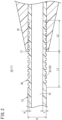
- the main catheter body 12 includes a flexible portion 30 whose flexibility for bending is increased compared to front and rear parts thereof by forming at least one groove 32 extending in the circumferential direction in an outer circumferential portion over a predetermined range from a distal side from a most distal portion 17 of the strain relief 16 to a proximal side from the most distal portion 17.
- the groove 32 is a portion dented by a depth H with respect to an outer diameter D (reference outer diameter) of the main catheter body 12. Therefore, a wall thickness of a portion of the main catheter body 12 in which the groove 32 is formed is thinner than a wall thickness T of a portion other than the flexible portion 30 by the depth H of the groove 32. In this way, the flexible portion 30 has higher flexibility than that of the front and rear parts of the flexible portion 30 in the main catheter body 12.
- the groove 32 extending in the circumferential direction is a helical groove 33.
- the helical groove 33 may be a single helix or a multiple helix such as a double helix.
- the helical groove 33 may not be a groove which is continuous from a distal end to a proximal end of the flexible portion 30, and may be intermitted at one or more places in the middle.
- the groove 32 may be an annular groove instead of the helical groove 33, and a plurality of (multiple) annular grooves may be formed in the outer circumferential portion of the main catheter body 12 at intervals in an axial direction.
- the depth H of the groove 32 with respect to a thickness T of a wall that forms the main catheter body 12 is set to 5 to 50%, preferably 20 to 40%.
- the depth H of the groove 32 is set to about 30 to 100 ⁇ m.
- a distance L1 from the most distal portion 17 of the strain relief 16 to a most distal portion of the flexible portion 30 (a most distal portion of the groove 32) is set to 5 to 50 mm, preferably 10 to 30 mm.
- a distance L2 from the most distal portion 17 of the strain relief 16 to a most proximal portion of the flexible portion 30 (a most proximal portion of the groove 32) is set to 5 to 50 mm, preferably 10 to 30 mm.
- the helical groove 33 may be formed by helicoidally winding a linear member (wire, or the like) around an outer peripheral surface of a tube-shaped compact, which is supported by a spindle and has the outer diameter D (the main catheter body 12 before the flexible portion 30 is formed), in a predetermined range in an axial direction, heating the linear member, and then removing the linear member.
- the groove 32 may be formed by helicoidally or annularly scraping the outer peripheral surface of the compact instead of using a method of using the linear member.
- the main catheter body 12 including the groove 32 may be manufactured by injection molding using an injection molding tool provided with a shape corresponding to the groove 32 in advance.
- the catheter 10 according to the present embodiment is basically configured as described above, and operations and effects thereof will be described below.
- the catheter 10 is configured as the introducer sheath 11.
- the introducer sheath 11 is combined with a dilator (not illustrated).
- an assembly in a state in which the dilator is inserted into the introducer sheath 11 punctures a blood vessel of a patient such that a distal end of the introducer sheath 11 secures the blood vessel.
- the main catheter body 12 is further inserted into the blood vessel and inserted up to a portion around the most distal portion 17 of the strain relief 16, and then the dilator is pulled out of the introducer sheath 11.
- a length in which the main catheter body 12 is inserted into the blood vessel is set to a predetermined length.
- a kink occurs when the amount of change of bending of the main catheter body 12 is greater than or equal to a certain extent.
- a distal portion of the strain relief 16 that is, around a boundary portion between a portion covered with the strain relief 16 and a portion not covered with the strain relief 16 in the main catheter body 12, bending rigidity greatly varies, and stress is easily concentrated.
- a kink easily occurs.
- the flexible portion 30, flexibility of which is increased by the groove 32, is provided in a front-rear range including the most distal portion 17 of the strain relief 16 in the main catheter body 12.
- the flexible portion 30 has higher flexibility than that of another portion of the main catheter body 12 in which the groove 32 is not provided, that is, a portion on a distal side and a portion on a proximal side from the flexible portion 30.
- the main catheter body 12 having the flexible portion 30 is more flexible with respect to bending when compared at the same outer diameter D. That is, when compared at the same outer diameter D, the amount of change of bending at which a kink may occur (allowed amount of change) is larger in the main catheter body 12 having the flexible portion 30 than in a conventional main catheter body not having the flexible portion 30.
- a more flexible portion that is, a less rigid portion than another portion in the axial direction is provided in a particular region on the proximal side of the main catheter body 12 and is allowed to be easily bent, thereby suppressing stress concentration due to bending, and inhibiting the occurrence of a kink. Therefore, according to the catheter 10, kink resistance of the main catheter body 12 may be increased while reducing a wall thickness.
- the groove 32 which is provided in the outer circumferential portion of the main catheter body 12 and extends in the circumferential direction, is the helical groove 33.
- the helical groove 33 is easily formed by winding the linear member around the outer circumferential portion of the tube-shaped compact, it is possible to easily manufacture the main catheter body 12 having the flexible portion 30 over the predetermined range in the axial direction.
- the flexible portion 30 includes the first sub-region 30A in which a groove 32A is formed at a relatively small pitch P1 and the second sub-region 30B in which a groove 32B is formed at a relatively large pitch P2. Therefore, the first sub-region 30A has higher flexibility with respect to bending than that of the second sub-region 30B.
- a range indicated by A refers to the first sub-region 30A and a range indicated by B refers to the second sub-region 30B in Fig. 3 .
- flexibility obtained by applying rigidity of the strain relief 16 to the main catheter body 12a is higher in a portion from a boundary portion C between the first sub-region 30A and the second sub-region 30B to the most distal portion 17 of the strain relief 16 than in a portion from the most distal portion 17 of the strain relief 16 to a most proximal portion of the second sub-region 30B.
- each of the grooves 32A and 32B in the first sub-region 30A and the second sub-region 30B is a helical groove.
- Each of the grooves 32A and 32B may correspond to a plurality of annular grooves form at intervals in an axial direction in place of the helical groove.
- the groove 32A of the first sub-region 30A and the groove 32B of the second sub-region 30B may communicate with each other, or may correspond to grooves independent from each other.
- the flexible portion 40 which includes the plurality of sub-regions (the first sub-region 30A and the second sub-region 30B) having different groove pitches, is provided, flexibility increases in stages toward the distal side in a front-rear region including the most distal portion 17 of the strain relief 16. For this reason, it is possible to more effectively suppress the occurrence of a kink in the main catheter body 12a. Note that three or more sub-regions having different groove pitches may be provided in the main catheter body 12a.
- a first sub-region 30A may have higher flexibility with respect to bending than that of a second sub-region 30B by setting a width W1 of a groove 32A of the first sub-region 30A to be larger than a width W2 of a groove 32B of the second sub-region 30B.
- the same effect as that of a configuration of Fig. 3 is obtained by a configuration of Fig. 4 .
- three or more sub-regions having different groove widths may be provided in the main catheter body 12b.
Landscapes
- Health & Medical Sciences (AREA)
- Life Sciences & Earth Sciences (AREA)
- Heart & Thoracic Surgery (AREA)
- Hematology (AREA)
- Anesthesiology (AREA)
- Biomedical Technology (AREA)
- Engineering & Computer Science (AREA)
- Pulmonology (AREA)
- Animal Behavior & Ethology (AREA)
- General Health & Medical Sciences (AREA)
- Public Health (AREA)
- Veterinary Medicine (AREA)
- Biophysics (AREA)
- Media Introduction/Drainage Providing Device (AREA)
Claims (4)
- Medizinischer Tubus (10), umfassend:einen flexiblen tubusförmigen Hauptkörper (12);eine Nabe (14), die mit einem proximalen Abschnitt des tubusförmigen Hauptkörpers (12) verbunden ist; undeine Zugentlastung (16), die an einem distalen Abschnitt der Nabe (14) gestützt wird, wobei die Zugentlastung (16) einen vorbestimmten Bereich einer proximalen Seite des tubusförmigen Hauptkörpers (12) umgibt;der tubusförmige Hauptkörper (12) einen flexiblen Abschnitt (30, 40 oder 42) aufweist, dessen Flexibilität zum Biegen durch das Ausbilden von mindestens einer Rille (32) erhöht wird, die sich in einer Umfangsrichtung in einem äußeren Umfangsabschnitt über einen vorbestimmten Bereich von einer distalen Seite von einem am weitesten distal gelegenen Abschnitt (17) der Zugentlastung (16) zu einer proximalen Seite von dem am weitesten distal gelegenen Abschnitt (17) erstreckt,dadurch gekennzeichnet, dassein Abstand (L1) von dem am weitesten distal gelegenen Abschnitt (17) der Zugentlastung (16) zu einem am weitesten distal gelegenen Abschnitt des flexiblen Abschnitts (30, 40 oder 42) auf 5 bis 50 mm, vorzugsweise auf 10 bis 30 mm, eingestellt ist; undein Abstand (L2) von dem am weitesten distal gelegenen Abschnitt (17) der Zugentlastung (16) zu einem am weitesten proximal gelegenen Abschnitt des flexiblen Abschnitts (30, 40 oder 42) auf 5 bis 50 mm, vorzugsweise auf 10 bis 30 mm, eingestellt ist;der medizinische Tubus (10) eine Einführschleuse (11) ist, die in ein Lumen eines lebenden Körpers eingeführt ist, um ein anderes langes medizinisches Instrument in den Körper einzuführen;eine Länge des tubusförmigen Hauptkörpers (12) in einem Bereich von ungefähr 20 bis 800 mm liegt;der flexible Abschnitt (30, 40 oder 42) eine höhere Flexibilität aufweist als derjenige der vorderen und der hinteren Teile des flexiblen Abschnitts (30, 40 oder 42) in dem tubusförmigen Hauptkörper (12) und der flexible Abschnitt (30, 40 oder 42) eine höhere Flexibilität aufweist als ein weiterer Abschnitt des tubusförmigen Hauptkörpers (12), in welchem die Rille nicht vorgesehen ist, das heißt, ein Abschnitt auf einer distalen Seite und ein Abschnitt auf einer proximalen Seite des flexiblen Abschnitts (30, 40 oder 42).
- Medizinischer Tubus (10) nach Anspruch 1, wobei die sich in Umfangsrichtung erstreckende Rille (32) eine spiralförmige Rille (33) ist.
- Medizinischer Tubus (10) nach Anspruch 1 oder 2, wobei der flexible Abschnitt (40 oder 42) eine Mehrzahl von Teilbereichen (30A und 30B) umfasst, von denen jeder eine unterschiedliche Steigung oder Breite in der Rille (32) aufweist, und
der Teilbereich (30A) auf einer distalen Seite in den Teilbereichen (30A und 30B), die benachbart zueinander sind, flexibler ist. - Medizinischer Tubus (10) nach Anspruch 3, wobei mindestens ein Grenzabschnitt (C) zwischen den Teilbereichen (30A und 30B) auf einer distalen Seite von dem am weitesten distal gelegenen Abschnitt (17) der Zugentlastung (16) angeordnet ist.
Applications Claiming Priority (2)
| Application Number | Priority Date | Filing Date | Title |
|---|---|---|---|
| JP2014051405 | 2014-03-14 | ||
| PCT/JP2015/054918 WO2015137098A1 (ja) | 2014-03-14 | 2015-02-23 | 医療用チューブ |
Publications (3)
| Publication Number | Publication Date |
|---|---|
| EP3117863A1 EP3117863A1 (de) | 2017-01-18 |
| EP3117863A4 EP3117863A4 (de) | 2017-10-25 |
| EP3117863B1 true EP3117863B1 (de) | 2025-04-16 |
Family
ID=54071547
Family Applications (1)
| Application Number | Title | Priority Date | Filing Date |
|---|---|---|---|
| EP15760901.7A Active EP3117863B1 (de) | 2014-03-14 | 2015-02-23 | Medizinischer tubus |
Country Status (4)
| Country | Link |
|---|---|
| US (1) | US10835712B2 (de) |
| EP (1) | EP3117863B1 (de) |
| JP (1) | JP6434495B2 (de) |
| WO (1) | WO2015137098A1 (de) |
Families Citing this family (42)
| Publication number | Priority date | Publication date | Assignee | Title |
|---|---|---|---|---|
| US9750928B2 (en) | 2013-02-13 | 2017-09-05 | Becton, Dickinson And Company | Blood control IV catheter with stationary septum activator |
| US9789279B2 (en) | 2014-04-23 | 2017-10-17 | Becton, Dickinson And Company | Antimicrobial obturator for use with vascular access devices |
| US10376686B2 (en) | 2014-04-23 | 2019-08-13 | Becton, Dickinson And Company | Antimicrobial caps for medical connectors |
| CN106255451B (zh) | 2014-05-06 | 2020-03-17 | 圣犹达医疗用品心脏病学部门有限公司 | 电极支撑结构组件 |
| US10118022B2 (en) | 2014-06-05 | 2018-11-06 | St. Jude Medical, Cardiology Division, Inc. | Deflectable catheter shaft section |
| US9844645B2 (en) | 2014-06-17 | 2017-12-19 | St. Jude Medical, Cardiology Division, Inc. | Triple coil catheter support |
| US10232088B2 (en) | 2014-07-08 | 2019-03-19 | Becton, Dickinson And Company | Antimicrobial coating forming kink resistant feature on a vascular access device |
| US10898096B2 (en) | 2014-10-27 | 2021-01-26 | St. Jude Medical, Cardiology Division, Inc. | Apparatus and method for connecting elements in medical devices |
| JP6514334B2 (ja) | 2015-01-28 | 2019-05-15 | セント・ジュード・メディカル,カーディオロジー・ディヴィジョン,インコーポレイテッド | 熱マッピング・カテーテル |
| US10602983B2 (en) | 2015-05-08 | 2020-03-31 | St. Jude Medical International Holding S.À R.L. | Integrated sensors for medical devices and method of making integrated sensors for medical devices |
| CN111657866B (zh) | 2015-10-21 | 2023-10-20 | 圣犹达医疗用品心脏病学部门有限公司 | 高密度电极标测导管 |
| CN114668490B (zh) | 2015-10-21 | 2025-10-03 | 圣犹达医疗用品心脏病学部门有限公司 | 高密度电极标测导管 |
| US10463840B2 (en) | 2015-10-28 | 2019-11-05 | Becton, Dickinson And Company | Compliant catheter adapter having self-slitting needle |
| US10493244B2 (en) | 2015-10-28 | 2019-12-03 | Becton, Dickinson And Company | Extension tubing strain relief |
| CN109310469B (zh) | 2016-05-03 | 2021-07-23 | 圣犹达医疗用品心脏病学部门有限公司 | 冲洗高密度电极导管 |
| EP3266486B1 (de) * | 2016-07-06 | 2019-01-30 | Abiomed Europe GmbH | Einführschleuse für gefässzugang |
| US11786705B2 (en) | 2016-10-24 | 2023-10-17 | St. Jude Medical, Cardiology Division, Inc. | Catheter insertion devices |
| US11172858B2 (en) | 2016-10-28 | 2021-11-16 | St. Jude Medical, Cardiology Division, Inc. | Flexible high-density mapping catheter |
| IL300057B2 (en) | 2016-12-08 | 2024-04-01 | Abiomed Inc | A design technique for peel-off penetrative design |
| JP7329442B2 (ja) | 2017-01-19 | 2023-08-18 | セント・ジュード・メディカル,カーディオロジー・ディヴィジョン,インコーポレイテッド | シースの可視化 |
| JP6940591B2 (ja) * | 2017-03-30 | 2021-09-29 | テルモ株式会社 | 酸素測定デバイス及び酸素測定システム |
| EP3616741B1 (de) * | 2017-04-28 | 2026-04-29 | Terumo Kabushiki Kaisha | Luftentfernungsmechanismus und einführschleuse |
| EP3606420B1 (de) | 2017-07-07 | 2023-05-24 | St. Jude Medical, Cardiology Division, Inc. | Geschichteter hochdichter elektrodenabbildungskatheter |
| JP2019017875A (ja) * | 2017-07-20 | 2019-02-07 | テルモ株式会社 | イントロデューサー用シース、およびイントロデューサー |
| US11647935B2 (en) | 2017-07-24 | 2023-05-16 | St. Jude Medical, Cardiology Division, Inc. | Masked ring electrodes |
| SG11202003104SA (en) | 2017-11-06 | 2020-05-28 | Abiomed Inc | Peel away hemostasis valve |
| EP4241819B1 (de) | 2017-11-28 | 2026-02-25 | St. Jude Medical, Cardiology Division, Inc. | Steuerbarer expandierbarer katheter |
| ES2894768T3 (es) * | 2017-12-15 | 2022-02-15 | Perfuze Ltd | Catéteres mejorados y dispositivos y sistemas que incorporan tales catéteres |
| CN117958829A (zh) | 2018-03-13 | 2024-05-03 | 圣犹达医疗用品心脏病学部门有限公司 | 可变密度标测导管 |
| WO2019195439A1 (en) | 2018-04-05 | 2019-10-10 | St. Jude Medical, Cardiology Division, Inc. | High density electrode mapping catheter |
| AU2019269627B2 (en) | 2018-05-16 | 2025-02-06 | Abiomed, Inc. | Peel-away sheath assembly |
| JP7499702B2 (ja) | 2018-05-21 | 2024-06-14 | セント・ジュード・メディカル,カーディオロジー・ディヴィジョン,インコーポレイテッド | 高周波アブレーション及び直流電気穿孔カテーテル |
| US12156979B2 (en) | 2018-05-21 | 2024-12-03 | St. Jude Medical, Cardiology Division, Inc. | Deflectable catheter shaft with pullwire anchor feature |
| US10946167B2 (en) | 2018-06-14 | 2021-03-16 | Covidien Lp | Catheter hub and strain relief |
| WO2020039392A2 (en) | 2018-08-23 | 2020-02-27 | St. Jude Medical, Cardiology Division, Inc. | Curved high density electrode mapping catheter |
| WO2020065587A2 (en) | 2018-09-27 | 2020-04-02 | St. Jude Medical, Cardiology Division, Inc. | Uniform mapping balloon |
| US11918762B2 (en) | 2018-10-03 | 2024-03-05 | St. Jude Medical, Cardiology Division, Inc. | Reduced actuation force electrophysiology catheter handle |
| JP7312556B2 (ja) * | 2019-01-25 | 2023-07-21 | テルモ株式会社 | カテーテル |
| WO2021192994A1 (ja) * | 2020-03-27 | 2021-09-30 | テルモ株式会社 | 医療用長尺体 |
| CN115942915B (zh) | 2020-08-18 | 2025-11-28 | 圣犹达医疗用品心脏病学部门有限公司 | 具有磁性位置跟踪的高密度电极导管 |
| JP7849983B2 (ja) * | 2022-02-21 | 2026-04-22 | 株式会社カネカ | 胆管用チューブステント |
| US12551658B2 (en) | 2022-03-25 | 2026-02-17 | St. Jude Medical, Cardiology Division, Inc. | Steerable introducer with slide block divider |
Citations (2)
| Publication number | Priority date | Publication date | Assignee | Title |
|---|---|---|---|---|
| US20080188793A1 (en) * | 2007-02-06 | 2008-08-07 | Possis Medical, Inc. | Miniature flexible thrombectomy catheter |
| US20090043283A1 (en) * | 2007-08-07 | 2009-02-12 | Boston Scientific Scimed, Inc. | Microfabricated catheter with improved bonding structure |
Family Cites Families (14)
| Publication number | Priority date | Publication date | Assignee | Title |
|---|---|---|---|---|
| JPS5914601U (ja) * | 1982-07-21 | 1984-01-28 | 旭光学工業株式会社 | 内視鏡のチヤンネル用チユ−ブ |
| US5569218A (en) * | 1994-02-14 | 1996-10-29 | Scimed Life Systems, Inc. | Elastic guide catheter transition element |
| US5466230A (en) * | 1994-06-09 | 1995-11-14 | Cordis Corporation | Catheter sheath introducer with strain relief |
| JPH0871161A (ja) | 1994-09-12 | 1996-03-19 | Terumo Corp | イントロデューサー |
| JPH08215312A (ja) * | 1995-02-09 | 1996-08-27 | Terumo Corp | バルーンカテーテル |
| JP3641381B2 (ja) * | 1999-03-10 | 2005-04-20 | テルモ株式会社 | 医療用チューブ及びその製造方法 |
| US6623448B2 (en) * | 2001-03-30 | 2003-09-23 | Advanced Cardiovascular Systems, Inc. | Steerable drug delivery device |
| US6997939B2 (en) * | 2001-07-02 | 2006-02-14 | Rubicon Medical, Inc. | Methods, systems, and devices for deploying an embolic protection filter |
| US7001369B2 (en) * | 2003-03-27 | 2006-02-21 | Scimed Life Systems, Inc. | Medical device |
| US20060264904A1 (en) * | 2005-05-09 | 2006-11-23 | Kerby Walter L | Medical device |
| US20100198160A1 (en) * | 2006-06-28 | 2010-08-05 | Abbott Vascular Inc. | Expandable Introducer Sheaths and Methods for Manufacture and Use |
| US20120071833A1 (en) * | 2007-03-02 | 2012-03-22 | Hill Roger J | Implantable catheter or lead anchor for implantable medical device system and method of use |
| US8409114B2 (en) * | 2007-08-02 | 2013-04-02 | Boston Scientific Scimed, Inc. | Composite elongate medical device including distal tubular member |
| JP2013022367A (ja) * | 2011-07-25 | 2013-02-04 | Goodman Co Ltd | カテーテル及びその製造方法 |
-
2015
- 2015-02-23 JP JP2016507427A patent/JP6434495B2/ja active Active
- 2015-02-23 EP EP15760901.7A patent/EP3117863B1/de active Active
- 2015-02-23 WO PCT/JP2015/054918 patent/WO2015137098A1/ja not_active Ceased
-
2016
- 2016-09-13 US US15/263,973 patent/US10835712B2/en active Active
Patent Citations (2)
| Publication number | Priority date | Publication date | Assignee | Title |
|---|---|---|---|---|
| US20080188793A1 (en) * | 2007-02-06 | 2008-08-07 | Possis Medical, Inc. | Miniature flexible thrombectomy catheter |
| US20090043283A1 (en) * | 2007-08-07 | 2009-02-12 | Boston Scientific Scimed, Inc. | Microfabricated catheter with improved bonding structure |
Also Published As
| Publication number | Publication date |
|---|---|
| US10835712B2 (en) | 2020-11-17 |
| WO2015137098A1 (ja) | 2015-09-17 |
| JPWO2015137098A1 (ja) | 2017-04-06 |
| EP3117863A1 (de) | 2017-01-18 |
| JP6434495B2 (ja) | 2018-12-05 |
| EP3117863A4 (de) | 2017-10-25 |
| US20160375222A1 (en) | 2016-12-29 |
Similar Documents
| Publication | Publication Date | Title |
|---|---|---|
| EP3117863B1 (de) | Medizinischer tubus | |
| EP3115076B1 (de) | Katheter | |
| EP2217314B1 (de) | Drainagekatheter | |
| US9463314B2 (en) | Delivery catheter apparatus and methods | |
| EP2015821B1 (de) | Abnehmbare ventile und verfahren zu ihrer herstellung | |
| EP2598194B1 (de) | Medizinische freisetzungssystem | |
| US9604030B2 (en) | Valves and hubs for tubular devices and methods for making and using them | |
| US9320873B2 (en) | Introducer sheath and introducer assembly | |
| EP2598199B1 (de) | Kathetervorrichtung | |
| US8734398B2 (en) | Sealing for medical devices/instruments | |
| US20210085920A1 (en) | Strain relief and methods of use thereof | |
| EP2740510B1 (de) | Dilatator | |
| EP4472710A1 (de) | Zentralvenöser katheter | |
| JP2005329063A (ja) | ダイレータ | |
| EP4454609A1 (de) | Abziehbarer vorschub für ein abgabesystem | |
| JP2005329062A (ja) | イントロデューサーシース | |
| JP2019176978A (ja) | 医療用長尺体、医療器具、および医療方法 |
Legal Events
| Date | Code | Title | Description |
|---|---|---|---|
| PUAI | Public reference made under article 153(3) epc to a published international application that has entered the european phase |
Free format text: ORIGINAL CODE: 0009012 |
|
| STAA | Information on the status of an ep patent application or granted ep patent |
Free format text: STATUS: REQUEST FOR EXAMINATION WAS MADE |
|
| 17P | Request for examination filed |
Effective date: 20160906 |
|
| AK | Designated contracting states |
Kind code of ref document: A1 Designated state(s): AL AT BE BG CH CY CZ DE DK EE ES FI FR GB GR HR HU IE IS IT LI LT LU LV MC MK MT NL NO PL PT RO RS SE SI SK SM TR |
|
| AX | Request for extension of the european patent |
Extension state: BA ME |
|
| DAX | Request for extension of the european patent (deleted) | ||
| A4 | Supplementary search report drawn up and despatched |
Effective date: 20170921 |
|
| RIC1 | Information provided on ipc code assigned before grant |
Ipc: A61M 39/22 20060101ALI20170915BHEP Ipc: A61M 25/04 20060101AFI20170915BHEP Ipc: A61M 25/00 20060101ALI20170915BHEP Ipc: A61M 25/06 20060101ALI20170915BHEP |
|
| STAA | Information on the status of an ep patent application or granted ep patent |
Free format text: STATUS: EXAMINATION IS IN PROGRESS |
|
| 17Q | First examination report despatched |
Effective date: 20220831 |
|
| GRAP | Despatch of communication of intention to grant a patent |
Free format text: ORIGINAL CODE: EPIDOSNIGR1 |
|
| STAA | Information on the status of an ep patent application or granted ep patent |
Free format text: STATUS: GRANT OF PATENT IS INTENDED |
|
| INTG | Intention to grant announced |
Effective date: 20250102 |
|
| GRAS | Grant fee paid |
Free format text: ORIGINAL CODE: EPIDOSNIGR3 |
|
| GRAA | (expected) grant |
Free format text: ORIGINAL CODE: 0009210 |
|
| STAA | Information on the status of an ep patent application or granted ep patent |
Free format text: STATUS: THE PATENT HAS BEEN GRANTED |
|
| AK | Designated contracting states |
Kind code of ref document: B1 Designated state(s): AL AT BE BG CH CY CZ DE DK EE ES FI FR GB GR HR HU IE IS IT LI LT LU LV MC MK MT NL NO PL PT RO RS SE SI SK SM TR |
|
| REG | Reference to a national code |
Ref country code: GB Ref legal event code: FG4D |
|
| REG | Reference to a national code |
Ref country code: CH Ref legal event code: EP Ref country code: DE Ref legal event code: R096 Ref document number: 602015091447 Country of ref document: DE |
|
| REG | Reference to a national code |
Ref country code: IE Ref legal event code: FG4D |
|
| REG | Reference to a national code |
Ref country code: NL Ref legal event code: MP Effective date: 20250416 |
|
| PG25 | Lapsed in a contracting state [announced via postgrant information from national office to epo] |
Ref country code: NL Free format text: LAPSE BECAUSE OF FAILURE TO SUBMIT A TRANSLATION OF THE DESCRIPTION OR TO PAY THE FEE WITHIN THE PRESCRIBED TIME-LIMIT Effective date: 20250416 |
|
| REG | Reference to a national code |
Ref country code: AT Ref legal event code: MK05 Ref document number: 1785140 Country of ref document: AT Kind code of ref document: T Effective date: 20250416 |
|
| PG25 | Lapsed in a contracting state [announced via postgrant information from national office to epo] |
Ref country code: ES Free format text: LAPSE BECAUSE OF FAILURE TO SUBMIT A TRANSLATION OF THE DESCRIPTION OR TO PAY THE FEE WITHIN THE PRESCRIBED TIME-LIMIT Effective date: 20250416 Ref country code: FI Free format text: LAPSE BECAUSE OF FAILURE TO SUBMIT A TRANSLATION OF THE DESCRIPTION OR TO PAY THE FEE WITHIN THE PRESCRIBED TIME-LIMIT Effective date: 20250416 Ref country code: PT Free format text: LAPSE BECAUSE OF FAILURE TO SUBMIT A TRANSLATION OF THE DESCRIPTION OR TO PAY THE FEE WITHIN THE PRESCRIBED TIME-LIMIT Effective date: 20250818 |
|
| REG | Reference to a national code |
Ref country code: LT Ref legal event code: MG9D |
|
| PG25 | Lapsed in a contracting state [announced via postgrant information from national office to epo] |
Ref country code: NO Free format text: LAPSE BECAUSE OF FAILURE TO SUBMIT A TRANSLATION OF THE DESCRIPTION OR TO PAY THE FEE WITHIN THE PRESCRIBED TIME-LIMIT Effective date: 20250716 Ref country code: GR Free format text: LAPSE BECAUSE OF FAILURE TO SUBMIT A TRANSLATION OF THE DESCRIPTION OR TO PAY THE FEE WITHIN THE PRESCRIBED TIME-LIMIT Effective date: 20250717 |
|
| PG25 | Lapsed in a contracting state [announced via postgrant information from national office to epo] |
Ref country code: PL Free format text: LAPSE BECAUSE OF FAILURE TO SUBMIT A TRANSLATION OF THE DESCRIPTION OR TO PAY THE FEE WITHIN THE PRESCRIBED TIME-LIMIT Effective date: 20250416 |
|
| PG25 | Lapsed in a contracting state [announced via postgrant information from national office to epo] |
Ref country code: BG Free format text: LAPSE BECAUSE OF FAILURE TO SUBMIT A TRANSLATION OF THE DESCRIPTION OR TO PAY THE FEE WITHIN THE PRESCRIBED TIME-LIMIT Effective date: 20250416 |
|
| PG25 | Lapsed in a contracting state [announced via postgrant information from national office to epo] |
Ref country code: HR Free format text: LAPSE BECAUSE OF FAILURE TO SUBMIT A TRANSLATION OF THE DESCRIPTION OR TO PAY THE FEE WITHIN THE PRESCRIBED TIME-LIMIT Effective date: 20250416 |
|
| PG25 | Lapsed in a contracting state [announced via postgrant information from national office to epo] |
Ref country code: AT Free format text: LAPSE BECAUSE OF FAILURE TO SUBMIT A TRANSLATION OF THE DESCRIPTION OR TO PAY THE FEE WITHIN THE PRESCRIBED TIME-LIMIT Effective date: 20250416 |
|
| PG25 | Lapsed in a contracting state [announced via postgrant information from national office to epo] |
Ref country code: RS Free format text: LAPSE BECAUSE OF FAILURE TO SUBMIT A TRANSLATION OF THE DESCRIPTION OR TO PAY THE FEE WITHIN THE PRESCRIBED TIME-LIMIT Effective date: 20250716 |
|
| PG25 | Lapsed in a contracting state [announced via postgrant information from national office to epo] |
Ref country code: IS Free format text: LAPSE BECAUSE OF FAILURE TO SUBMIT A TRANSLATION OF THE DESCRIPTION OR TO PAY THE FEE WITHIN THE PRESCRIBED TIME-LIMIT Effective date: 20250816 |
|
| PG25 | Lapsed in a contracting state [announced via postgrant information from national office to epo] |
Ref country code: LV Free format text: LAPSE BECAUSE OF FAILURE TO SUBMIT A TRANSLATION OF THE DESCRIPTION OR TO PAY THE FEE WITHIN THE PRESCRIBED TIME-LIMIT Effective date: 20250416 |
|
| PG25 | Lapsed in a contracting state [announced via postgrant information from national office to epo] |
Ref country code: DK Free format text: LAPSE BECAUSE OF FAILURE TO SUBMIT A TRANSLATION OF THE DESCRIPTION OR TO PAY THE FEE WITHIN THE PRESCRIBED TIME-LIMIT Effective date: 20250416 Ref country code: SM Free format text: LAPSE BECAUSE OF FAILURE TO SUBMIT A TRANSLATION OF THE DESCRIPTION OR TO PAY THE FEE WITHIN THE PRESCRIBED TIME-LIMIT Effective date: 20250416 |
|
| PGFP | Annual fee paid to national office [announced via postgrant information from national office to epo] |
Ref country code: FR Payment date: 20251231 Year of fee payment: 12 |
|
| REG | Reference to a national code |
Ref country code: DE Ref legal event code: R097 Ref document number: 602015091447 Country of ref document: DE |
|
| PG25 | Lapsed in a contracting state [announced via postgrant information from national office to epo] |
Ref country code: CZ Free format text: LAPSE BECAUSE OF FAILURE TO SUBMIT A TRANSLATION OF THE DESCRIPTION OR TO PAY THE FEE WITHIN THE PRESCRIBED TIME-LIMIT Effective date: 20250416 |
|
| PG25 | Lapsed in a contracting state [announced via postgrant information from national office to epo] |
Ref country code: EE Free format text: LAPSE BECAUSE OF FAILURE TO SUBMIT A TRANSLATION OF THE DESCRIPTION OR TO PAY THE FEE WITHIN THE PRESCRIBED TIME-LIMIT Effective date: 20250416 |
|
| PG25 | Lapsed in a contracting state [announced via postgrant information from national office to epo] |
Ref country code: RO Free format text: LAPSE BECAUSE OF FAILURE TO SUBMIT A TRANSLATION OF THE DESCRIPTION OR TO PAY THE FEE WITHIN THE PRESCRIBED TIME-LIMIT Effective date: 20250416 Ref country code: SK Free format text: LAPSE BECAUSE OF FAILURE TO SUBMIT A TRANSLATION OF THE DESCRIPTION OR TO PAY THE FEE WITHIN THE PRESCRIBED TIME-LIMIT Effective date: 20250416 |
|
| PG25 | Lapsed in a contracting state [announced via postgrant information from national office to epo] |
Ref country code: IT Free format text: LAPSE BECAUSE OF FAILURE TO SUBMIT A TRANSLATION OF THE DESCRIPTION OR TO PAY THE FEE WITHIN THE PRESCRIBED TIME-LIMIT Effective date: 20250416 |
|
| PLBE | No opposition filed within time limit |
Free format text: ORIGINAL CODE: 0009261 |
|
| STAA | Information on the status of an ep patent application or granted ep patent |
Free format text: STATUS: NO OPPOSITION FILED WITHIN TIME LIMIT |
|
| REG | Reference to a national code |
Ref country code: CH Ref legal event code: L10 Free format text: ST27 STATUS EVENT CODE: U-0-0-L10-L00 (AS PROVIDED BY THE NATIONAL OFFICE) Effective date: 20260225 |
|
| 26N | No opposition filed |
Effective date: 20260119 |
|
| PGFP | Annual fee paid to national office [announced via postgrant information from national office to epo] |
Ref country code: GB Payment date: 20260106 Year of fee payment: 12 |