EP2628559A2 - Stirnabwälzfräsersystem und Wendefräsplatten dafür - Google Patents
Stirnabwälzfräsersystem und Wendefräsplatten dafür Download PDFInfo
- Publication number
- EP2628559A2 EP2628559A2 EP13155004.8A EP13155004A EP2628559A2 EP 2628559 A2 EP2628559 A2 EP 2628559A2 EP 13155004 A EP13155004 A EP 13155004A EP 2628559 A2 EP2628559 A2 EP 2628559A2
- Authority
- EP
- European Patent Office
- Prior art keywords
- inserts
- tangential
- cartridge assemblies
- milling
- face hobbing
- Prior art date
- Legal status (The legal status is an assumption and is not a legal conclusion. Google has not performed a legal analysis and makes no representation as to the accuracy of the status listed.)
- Granted
Links
Images


Classifications
-
- B—PERFORMING OPERATIONS; TRANSPORTING
- B23—MACHINE TOOLS; METAL-WORKING NOT OTHERWISE PROVIDED FOR
- B23F—MAKING GEARS OR TOOTHED RACKS
- B23F21/00—Tools specially adapted for use in machines for manufacturing gear teeth
- B23F21/12—Milling tools
-
- B—PERFORMING OPERATIONS; TRANSPORTING
- B23—MACHINE TOOLS; METAL-WORKING NOT OTHERWISE PROVIDED FOR
- B23F—MAKING GEARS OR TOOTHED RACKS
- B23F21/00—Tools specially adapted for use in machines for manufacturing gear teeth
- B23F21/12—Milling tools
- B23F21/22—Face-mills for longitudinally-curved gear teeth
- B23F21/223—Face-mills for longitudinally-curved gear teeth with inserted cutting elements
- B23F21/226—Face-mills for longitudinally-curved gear teeth with inserted cutting elements in exchangeable arrangement
-
- B—PERFORMING OPERATIONS; TRANSPORTING
- B23—MACHINE TOOLS; METAL-WORKING NOT OTHERWISE PROVIDED FOR
- B23C—MILLING
- B23C5/00—Milling-cutters
- B23C5/16—Milling-cutters characterised by physical features other than shape
- B23C5/20—Milling-cutters characterised by physical features other than shape with removable cutter bits or teeth or cutting inserts
-
- B—PERFORMING OPERATIONS; TRANSPORTING
- B23—MACHINE TOOLS; METAL-WORKING NOT OTHERWISE PROVIDED FOR
- B23F—MAKING GEARS OR TOOTHED RACKS
- B23F17/00—Special methods or machines for making gear teeth, not covered by the preceding groups
- B23F17/003—Special methods or machines for making gear teeth, not covered by the preceding groups for dry cutting
-
- B—PERFORMING OPERATIONS; TRANSPORTING
- B23—MACHINE TOOLS; METAL-WORKING NOT OTHERWISE PROVIDED FOR
- B23F—MAKING GEARS OR TOOTHED RACKS
- B23F21/00—Tools specially adapted for use in machines for manufacturing gear teeth
- B23F21/12—Milling tools
- B23F21/16—Hobs
-
- Y—GENERAL TAGGING OF NEW TECHNOLOGICAL DEVELOPMENTS; GENERAL TAGGING OF CROSS-SECTIONAL TECHNOLOGIES SPANNING OVER SEVERAL SECTIONS OF THE IPC; TECHNICAL SUBJECTS COVERED BY FORMER USPC CROSS-REFERENCE ART COLLECTIONS [XRACs] AND DIGESTS
- Y02—TECHNOLOGIES OR APPLICATIONS FOR MITIGATION OR ADAPTATION AGAINST CLIMATE CHANGE
- Y02P—CLIMATE CHANGE MITIGATION TECHNOLOGIES IN THE PRODUCTION OR PROCESSING OF GOODS
- Y02P70/00—Climate change mitigation technologies in the production process for final industrial or consumer products
- Y02P70/10—Greenhouse gas [GHG] capture, material saving, heat recovery or other energy efficient measures, e.g. motor control, characterised by manufacturing processes, e.g. for rolling metal or metal working
-
- Y—GENERAL TAGGING OF NEW TECHNOLOGICAL DEVELOPMENTS; GENERAL TAGGING OF CROSS-SECTIONAL TECHNOLOGIES SPANNING OVER SEVERAL SECTIONS OF THE IPC; TECHNICAL SUBJECTS COVERED BY FORMER USPC CROSS-REFERENCE ART COLLECTIONS [XRACs] AND DIGESTS
- Y10—TECHNICAL SUBJECTS COVERED BY FORMER USPC
- Y10T—TECHNICAL SUBJECTS COVERED BY FORMER US CLASSIFICATION
- Y10T407/00—Cutters, for shaping
- Y10T407/17—Gear cutting tool
- Y10T407/1705—Face mill gear cutting tool
- Y10T407/171—Adjustable teeth
-
- Y—GENERAL TAGGING OF NEW TECHNOLOGICAL DEVELOPMENTS; GENERAL TAGGING OF CROSS-SECTIONAL TECHNOLOGIES SPANNING OVER SEVERAL SECTIONS OF THE IPC; TECHNICAL SUBJECTS COVERED BY FORMER USPC CROSS-REFERENCE ART COLLECTIONS [XRACs] AND DIGESTS
- Y10—TECHNICAL SUBJECTS COVERED BY FORMER USPC
- Y10T—TECHNICAL SUBJECTS COVERED BY FORMER US CLASSIFICATION
- Y10T407/00—Cutters, for shaping
- Y10T407/17—Gear cutting tool
- Y10T407/1715—Hob
-
- Y—GENERAL TAGGING OF NEW TECHNOLOGICAL DEVELOPMENTS; GENERAL TAGGING OF CROSS-SECTIONAL TECHNOLOGIES SPANNING OVER SEVERAL SECTIONS OF THE IPC; TECHNICAL SUBJECTS COVERED BY FORMER USPC CROSS-REFERENCE ART COLLECTIONS [XRACs] AND DIGESTS
- Y10—TECHNICAL SUBJECTS COVERED BY FORMER USPC
- Y10T—TECHNICAL SUBJECTS COVERED BY FORMER US CLASSIFICATION
- Y10T409/00—Gear cutting, milling, or planing
- Y10T409/10—Gear cutting
- Y10T409/101431—Gear tooth shape generating
- Y10T409/10477—Gear tooth shape generating by relative axial movement between synchronously indexing or rotating work and cutter
- Y10T409/105088—Displacing cutter axially relative to work [e.g., gear shaving, etc.]
- Y10T409/105247—Using gear shaper-cutter
Definitions
- the present invention relates to a gear face hobbing cutter system and, in particular, to an adjustable, cartridged face hobbing cutter system for face hobbing spiral bevel gears on CNC Face Hobbing machines.
- the present invention further relates to indexable milling inserts for use in the spiral bevel gear face hobbing cutter system.
- Bevel gears are widely used in trucks, construction vehicles and mining machinery. The current trend is that the potential is still in growing. At present, there are mainly two versions of bevel gears in the market. The first type is the bevel gears manufactured by Gleason, Germany, and the second type is the bevel gears manufactured by Klingelnberg, Germany. Thousands of tools for face hobbing Gleason version bevel gears exist in the market.
- the milling cutter and the workpiece rotate independently in a timing relationship with each other, thereby allowing continue indexing of the workpiece and continual formation of the gear teeth.
- a single plunge of the cutting tool can result in all the teeth of the gear being formed.
- tool bits of high speed steel are predominantly employed to face hob the spiral bevel gears.
- blades of high speed steel or solid carbide blades with various coatings are employed to face hob the spiral bevel gears.
- the blades can be re-sharpened and re-coated, which, however, consumes time and requires high cost.
- the existing cutting tools are also adjustable in radial and angular planes. Gleason version cutting tools have several styles in order to meet requirements on low and high volume production, and roughing to finishing machining.
- US patents US 6,715,968 and US 6,086,291 disclose a grooving insert, which can be used for milling tooth roots.
- German patent DE 20016673 discloses a milling cutter assembly, which can be used for milling tooth flanks, and in which inserts having rectangular basic shapes are employed.
- US patent US 6,632,050 B2 discloses a face hobbing cutter system, in which blades are employed.
- WO 00/66310 discloses a face hobbing cutter system for face hobbing gears.
- US patents US 6,609,858 and US 7,736,099 disclose cartridged, face hobbing cutter systems. For example, Fig.
- the reference sign 1 denotes the gear milling cutter system
- the reference sign 2 denotes the cutter disc
- the reference sign 3 denotes the top surface of the cutter disc
- the reference sign 4 denotes the cartridge assemblies
- the reference sign 5 denotes the side surface of the cutter disc
- the reference sign 6 denotes the slots.
- the cartridge assemblies 4 are arranged in two rows, i.e., an inside row and an outside row, for respectively milling the inner side and the outer side of the gear teeth
- the cartridge assemblies each include a cartridges and an indexable insert, all the cartridges and inserts being the same.
- the present invention aims at avoiding the above previously known disadvantages of the gear face hobbing cutters and provide a gear face hobbing cutter system, which is particularly suitable for machining spiral bevel gears and, in particular, for machining Gleason version spiral bevel gears with a module of 5-20.
- the main object of the present invention is to provide a gear face hobbing cutter system for roughing and semi-finishing operation of spiral bevel gears, in which different cartridges and indexable inserts are utilized to machine different parts of the spiral bevel gear teeth, instead of utilizing the HSS cutter bits and the solid carbide blades that are predominately used at present, or the cartridges and inserts that are the same and arranged in inside and outside rows so as to machine the inner sides and the outer sides of the gear teeth.
- the utilization of different cartridges and indexable inserts to machine the spiral bevel gears in the gear face hobbing system has the following advantages: higher metal removal rate, dry cutting, longer tool life, and less set-up time.
- Another object of the present invention is to provide tangential-mounted indexable milling inserts for use in the above gear face hobbing cutter system, the inserts being used for machining the tooth flanks of the gear teeth.
- a face hobbing cutter system for face hobbing spiral bevel gears which comprises, on one hand, a cutter disc rotatable about a central axis and having a rotationally symmetrical basic shape, the cutter disc including a top surface, a bottom surface and a side surface extending between the top surface and the bottom surface, and a plurality of pockets formed in the cutter disc for receiving cartridge assemblies and extending inwards from the top surface into the cutter disc, and which comprises, on the other hand, at least one set of detachable cartridge assemblies, each set of cartridge assemblies including a plurality of cartridge assemblies, the respective cartridge assemblies being spaced apart along a rotational direction, each cartridge assembly being fixed in place in its respective pocket by a clamping device, each cartridge assembly including cartridges and indexable milling inserts, and each milling insert being retained on its respective cartridge by a retaining device, characterized in that a part of the milling inserts in each set of cartridge assemblies are provided as tangential-mounted inserts for milling
- the grooving inserts and the tangential-mounted inserts are arranged in such a way that the grooving inserts have their respective most radially distanced point from the central axis at a larger radial distance than the respective most radially distanced point of the tangential-mounted inserts.
- the milling inserts in each set of cartridge assemblies are alternately provided in the following order: a grooving insert, a first tangential-mounted insert, a grooving insert, a second tangential-mounted insert, wherein the second tangential-mounted insert is tangentially mounted in an opposite direction as the first tangential-mounted insert.
- the cutter system is mounted with an equal number of grooving inserts and tangential-mounted inserts, wherein the tangential-mounted inserts are mounted in equal amount from two opposite directions. With this configuration, more cutting inserts are configured to cut the roots, and less cutting inserts are configured to cut each of the flanks.
- the respective cartridge assemblies are equidistantly spaced apart along the rotational direction.
- the face hobbing cutter system comprises 2-7 sets of cartridge assemblies, the respective sets of cartridge assemblies being evenly spaced apart along the rotational direction.
- each set of cartridge assemblies comprises 3-6 different cartridges to correspondingly hold the different milling inserts.
- the face hobbing system comprises 7 sets of cartridge assemblies, each set of cartridge assemblies including four cartridge assemblies, two of the milling inserts of the four cartridge assemblies being grooving inserts, and the other two of the milling inserts of the four cartridge assemblies being tangential-mounted insert, to form a complete gear tooth profile.
- the tangential-mounted insert has at least two cutting edges, preferably four cutting edges.
- the cartridge assembly further comprises a shim for providing an accurate radial setting of the cartridge assembly.
- the present invention further relates to the above indexable tangential-mounted inserts, which can be made of solid carbide and can be coated with coatings.
- the face hobbing cutter system according to the present invention can be used for roughing and semi-finishing operation of spiral bevel gears.
- Preferable machining parameters are as follows: a linear cutting velocity Vc of less than 350 m/min, and a feed per tooth fz of 0.25 mm at maximum.
- different inserts are utilized to machine different parts of the spiral bevel gear teeth, and the inserts for machining the flanks are particularly tangential-mounted and each have a rhombic basic shapes.
- High productivity, dry cutting and less set-up time when machining spiral bevel gears are achieved by the gear face hobbing cutter system of the present invention.
- the power load on meter when machining spiral bevel gears is low and the surface quality of the manufactured gear tooth is good.
- Another benefit with the designated inserts for the root and flanks is that it is possible to optimize the respective inserts. For example, using a more wear resistant grade insert for the flanks, and using a tougher grade insert for the root.
- the indexable tangential-mounted insert has at least two cutting edges, preferably fourth cutting edges, and is an insert having a rhombic basic shape, a positive axial inclination angle is achieved, which facilitates a better chip removal during machining, and the life of the cutting tool is long.
- tangential-mounted is used by referring to the rotational machining direction of the face hobbing cutter system.
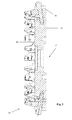
- a face hobbing cutter system for face hobing spiral bevel gears of the present invention comprises, on one hand, a cutter disc 10 rotating about a central axis C and having a rotationally symmetrical basic shape, the cutter disc 10 including a top surface 20, a bottom surface 30 and a side surface 40 extending between the top surface and the bottom surface, and a plurality of pockets 50 formed in the cutter disc for receiving cartridge assemblies and extending inwards from the top surface into the cutter disc, and comprises, on the other hand, 7 sets of detachable cartridge assemblies, the respective sets of cartridge assemblies being evenly spaced apart along a rotational direction, each set of cartridge assemblies including four cartridge assemblies 100, 200, 300, 400, the respective cartridge assemblies being equidistantly spaced apart along the rotational direction, each cartridge assembly being fixed in place in its respective pocket by a clamping device (not designated), each cartridge assembly including cartridges 110, 210, 310, 410 and indexable milling inserts 120, 220, 320,
- 2 inserts are provided as tangential-mounted inserts 220, 420 for milling flanks of spiral bevel gear teeth
- the other 2 inserts are provide as grooving inserts 120, 320, which are arranged transversely to the tangential-mounted inserts, for milling roots of the spiral bevel gear teeth.
- One (220 in this embodiment) of the tangential-mounted inserts 220, 420 of each set of cartridge assemblies is provided with its front facing the central axis, and the other (420 in this embodiment) thereof is provided with its front facing away the central axis, for respectively milling concave curved flanks and convex curved flanks of the spiral bevel gear teeth.
- the grooving inserts 120 and 320 each have their respective most distanced point from the top surface 20 of the disc at a larger distance from the top surface 20 than the corresponding distance for the tangential-mounted inserts 220 and 420.
- each set of cartridge assemblies is mounted with an equal number of grooving inserts and tangential-mounted inserts, wherein the tangential-mounted inserts 220 and 420 are mounted in equal amount from two opposite directions.
- more cutting inserts are configured to cut the roots, and less cutting inserts are configured to cut each of the flanks.
- the cartridge assembly can further comprise a shim for providing an accurate radial setting of the cartridge assembly.
- the indexable tangential-mounted inserts of the present invention are described below according to Figs. 6, 6A and 6B .
- the tangential-mounted inserts 220, 420 each have a rhombic basic shape and have four cutting edges.
- the face hobbing cutter system of the present invention is particularly suitable for roughing and semi-finishing operation of spiral bevel gears.
- Proper machining parameters are as follows: a linear cutting velocity Vc of less than 350 m/min, and a feed per tooth fz of 0.25 mm at maximum.
- a 28 cutter pocket 12" (about 30 cm) cutter disc, on which 28 cartridge assemblies were mounted (the cartridges are obtained from Sandvik Coromant, Sweden), manufactured by Harbin No. 1 Tool Works was used.
- the cartridge assemblies were divided into seven sets in total, each set including 4 cartridge assemblies, two of the milling inserts of the 4 cartridge assemblies being provided as tangential-mounted inserts for machining the flanks of the spiral bevel gear teeth, and the other two of the milling inserts being provided as grooving inserts (CoroCut inserts of Sandvik Coromant, Sweden) for machining the roots of the gear teeth.
- the grooving inserts were provided transversely to the tangential-mounted inserts.
- One of the two tangential-mounted inserts was provided with its front facing the central axis, and the other thereof was provided with its front facing away the central axis, for respectively milling concave curved flanks and convex curved flanks of the gear teeth.
- the tangential-mounted inserts each had a rhombic basic shape.
- the cartridge assembly further comprises a soft shim.
- the cartridges were adjusted to 5 microns run out radially and the height variance was 30 microns.
- the assembled face hobbing cutter system was mounted on the JCB60 type CNC machine to machine a Gleason version spiral bevel gear.
- the material of the workpiece was low alloy steel.
- the hardness of the workpiece was 150HB.
- the machining condition was dry milling.
- the cutting time for each tooth was 10 seconds.
- the machining speed was too slow.
- chip welding occurred in the milled gear, and the grooving inserts for machining the roots were chipped.
- the machining condition was dry milling.
- the cutting time for each tooth was 5 seconds.
- the machining speed was acceptable.
- the quality of the milled gear is acceptable.
- the power load on meter is 26%.
- the cutting tool dwelled in roots for 0.15-0.3 second after machining the roots.
- the machining condition was dry milling.
- the cutting time for each tooth was 3.5 seconds.
- the machining speed was very fast. Besides, vibration patterns occurred in the surfaces of the roots during machining were small, and the quality of the milled gear was excellent.
- the power load on meter was 38%.
- the utilization of the face hobbing cutter system according to the present invention to machine the spiral bevel gears achieves a fast machining speed, an improved productivity and a good surface finish (a measurement of a Class 6 gear rating on profile tolerance) of the milled gears.
- the machining condition is dry cutting, which requires no cooling liquid.
- the wear of the cutting tool is small, and the life of the cutting tool is improved.
- the cutting is smooth, and the vibration patterns occurred in the roots during machining are small.
- the cartridge assembly further has a soft shim, thereby providing an accurate radial adjustment in order to be adapted for gears of different sizes.
Landscapes
- Engineering & Computer Science (AREA)
- Mechanical Engineering (AREA)
- Gear Processing (AREA)
- Milling Processes (AREA)
Applications Claiming Priority (1)
| Application Number | Priority Date | Filing Date | Title |
|---|---|---|---|
| CN201210035560.1A CN103252538B (zh) | 2012-02-16 | 2012-02-16 | 面滚铣刀系统及用于该面滚铣刀系统的可转位铣削刀片 |
Publications (3)
| Publication Number | Publication Date |
|---|---|
| EP2628559A2 true EP2628559A2 (de) | 2013-08-21 |
| EP2628559A3 EP2628559A3 (de) | 2017-08-23 |
| EP2628559B1 EP2628559B1 (de) | 2020-12-09 |
Family
ID=47709984
Family Applications (1)
| Application Number | Title | Priority Date | Filing Date |
|---|---|---|---|
| EP13155004.8A Not-in-force EP2628559B1 (de) | 2012-02-16 | 2013-02-13 | Stirnabwälzfräsersystem und Verwendung des Selben |
Country Status (5)
| Country | Link |
|---|---|
| US (1) | US9339880B2 (de) |
| EP (1) | EP2628559B1 (de) |
| JP (1) | JP6200162B2 (de) |
| KR (1) | KR20130094758A (de) |
| CN (1) | CN103252538B (de) |
Cited By (2)
| Publication number | Priority date | Publication date | Assignee | Title |
|---|---|---|---|---|
| EP2871015A1 (de) * | 2013-11-11 | 2015-05-13 | Sandvik Intellectual Property AB | Zahnradabwälzwerkzeug sowie Einsatzhalter, Chip-Entfernungseinheit, und Einsatzkit dafür |
| CN119457217A (zh) * | 2024-12-30 | 2025-02-18 | 株洲百斯特福工具有限公司 | 小径丝杠螺母滚道加工用可转位铣刀 |
Families Citing this family (10)
| Publication number | Priority date | Publication date | Assignee | Title |
|---|---|---|---|---|
| KR101517979B1 (ko) * | 2014-07-08 | 2015-05-06 | 한국야금 주식회사 | 절삭 인서트 및 이를 장착한 절삭 공구 |
| JP6618742B2 (ja) * | 2015-09-15 | 2019-12-11 | 株式会社Subaru | ブレード固定構造 |
| US11173559B2 (en) * | 2017-07-13 | 2021-11-16 | The Gleason Works | Bevel gear cutter and blade consolidation |
| CN107962256A (zh) * | 2017-12-27 | 2018-04-27 | 湖南中大创远数控装备有限公司 | 用于加工螺旋锥齿轮产品的刀盘 |
| US10384270B1 (en) * | 2018-03-08 | 2019-08-20 | Honda Motor Co., Ltd. | Cutting tool |
| CN109794635A (zh) * | 2019-02-24 | 2019-05-24 | 江苏扬碟钻石工具有限公司 | 一种新型铣刀盘 |
| CN110158691B (zh) * | 2019-05-16 | 2024-03-01 | 江苏徐工工程机械研究院有限公司 | 一种铣齿及双轮铣铣削装置 |
| CN114029560B (zh) * | 2021-11-30 | 2023-07-14 | 四川大学 | 一种加工变双曲圆弧齿线圆柱齿轮的刀具组合及加工方法 |
| CN115178762B (zh) * | 2022-08-01 | 2025-11-11 | 江苏环欧智能传动设备有限公司 | 一种克制螺伞软切刀具结构 |
| CN117047204B (zh) * | 2023-09-04 | 2024-04-30 | 哈尔滨东安利峰刀具有限公司 | 一种双联可转位齿轮粗铣刀组件 |
Citations (7)
| Publication number | Priority date | Publication date | Assignee | Title |
|---|---|---|---|---|
| US6086291A (en) | 1997-09-24 | 2000-07-11 | Sandvik Ab | Tool for chip removing machining |
| WO2000066310A2 (en) | 1999-05-05 | 2000-11-09 | The Gleason Works | Method for producing a cutting tool for face hobbing gears |
| DE20016673U1 (de) | 2000-09-27 | 2000-12-14 | Ingersoll Werkzeuge GmbH, 57299 Burbach | Zahnformfräser |
| US6609858B1 (en) | 2002-04-18 | 2003-08-26 | Kennametal Inc. | Gear hobbing cutter system |
| US6632050B2 (en) | 2001-09-06 | 2003-10-14 | Kennametal Inc. | Face hobbing cutter |
| US6715968B1 (en) | 1998-09-09 | 2004-04-06 | Sandvik Aktiebolag | Cutting insert for grooving operations |
| US7736099B2 (en) | 2005-12-16 | 2010-06-15 | Cole Carbide Industries, Inc. | Gear milling tool with replaceable cutting inserts |
Family Cites Families (16)
| Publication number | Priority date | Publication date | Assignee | Title |
|---|---|---|---|---|
| US1931169A (en) * | 1929-01-02 | 1933-10-17 | Gleason Works | Gear cutting tool |
| US1969843A (en) * | 1931-01-02 | 1934-08-14 | Gleason Works | Cutter for and method of cutting gears |
| FR956482A (de) * | 1943-02-11 | 1950-02-02 | ||
| US2930112A (en) * | 1957-07-01 | 1960-03-29 | Gleason Works | Adjustable cutter for spiral bevel gears and the like |
| JPS5614407B2 (de) * | 1973-11-14 | 1981-04-03 | ||
| JPS63201019U (de) * | 1987-06-18 | 1988-12-26 | ||
| JPH07110448B2 (ja) * | 1988-03-07 | 1995-11-29 | 日産自動車株式会社 | 傘歯車加工用環状フライスカッタ |
| US5290135A (en) * | 1992-10-28 | 1994-03-01 | The Gleason Works | Rotary ring cutter having coolant distribution and discharge means |
| WO2003089203A1 (en) * | 2002-04-18 | 2003-10-30 | Kennametal Inc. | Gear hobbing cutter system |
| JP2005177938A (ja) * | 2003-12-19 | 2005-07-07 | Mitsubishi Fuso Truck & Bus Corp | ベベルギヤカッタ |
| CN2810845Y (zh) * | 2005-07-18 | 2006-08-30 | 哈尔滨第一工具有限公司 | 硬质合金弧齿锥齿轮铣刀 |
| DE202007007063U1 (de) * | 2007-05-16 | 2007-09-27 | Klingelnberg Ag | Kegelradfräswerkzeug mit Frässchneidplatten |
| US8113750B2 (en) * | 2007-10-15 | 2012-02-14 | Ford Motor Company | Face hob hypoid gear tooth cutting by common blades |
| EP2181789B1 (de) * | 2008-10-30 | 2011-06-15 | Klingelnberg AG | Universal einsetzbarer Stabmesserkopf und Verwendung desselben |
| JP5541930B2 (ja) * | 2009-01-08 | 2014-07-09 | 富士重工業株式会社 | 工具ヘッド |
| CN102179570B (zh) * | 2011-04-02 | 2012-08-22 | 长沙哈量凯帅精密机械有限公司 | 一种加工摆线-渐开线螺旋锥齿轮的方法与整体刀盘 |
-
2012
- 2012-02-16 CN CN201210035560.1A patent/CN103252538B/zh not_active Expired - Fee Related
-
2013
- 2013-02-13 EP EP13155004.8A patent/EP2628559B1/de not_active Not-in-force
- 2013-02-14 US US13/766,905 patent/US9339880B2/en not_active Expired - Fee Related
- 2013-02-15 JP JP2013028182A patent/JP6200162B2/ja not_active Expired - Fee Related
- 2013-02-15 KR KR1020130016609A patent/KR20130094758A/ko not_active Withdrawn
Patent Citations (7)
| Publication number | Priority date | Publication date | Assignee | Title |
|---|---|---|---|---|
| US6086291A (en) | 1997-09-24 | 2000-07-11 | Sandvik Ab | Tool for chip removing machining |
| US6715968B1 (en) | 1998-09-09 | 2004-04-06 | Sandvik Aktiebolag | Cutting insert for grooving operations |
| WO2000066310A2 (en) | 1999-05-05 | 2000-11-09 | The Gleason Works | Method for producing a cutting tool for face hobbing gears |
| DE20016673U1 (de) | 2000-09-27 | 2000-12-14 | Ingersoll Werkzeuge GmbH, 57299 Burbach | Zahnformfräser |
| US6632050B2 (en) | 2001-09-06 | 2003-10-14 | Kennametal Inc. | Face hobbing cutter |
| US6609858B1 (en) | 2002-04-18 | 2003-08-26 | Kennametal Inc. | Gear hobbing cutter system |
| US7736099B2 (en) | 2005-12-16 | 2010-06-15 | Cole Carbide Industries, Inc. | Gear milling tool with replaceable cutting inserts |
Cited By (2)
| Publication number | Priority date | Publication date | Assignee | Title |
|---|---|---|---|---|
| EP2871015A1 (de) * | 2013-11-11 | 2015-05-13 | Sandvik Intellectual Property AB | Zahnradabwälzwerkzeug sowie Einsatzhalter, Chip-Entfernungseinheit, und Einsatzkit dafür |
| CN119457217A (zh) * | 2024-12-30 | 2025-02-18 | 株洲百斯特福工具有限公司 | 小径丝杠螺母滚道加工用可转位铣刀 |
Also Published As
| Publication number | Publication date |
|---|---|
| EP2628559A3 (de) | 2017-08-23 |
| JP2013166242A (ja) | 2013-08-29 |
| KR20130094758A (ko) | 2013-08-26 |
| US9339880B2 (en) | 2016-05-17 |
| EP2628559B1 (de) | 2020-12-09 |
| CN103252538A (zh) | 2013-08-21 |
| US20140056657A1 (en) | 2014-02-27 |
| JP6200162B2 (ja) | 2017-09-20 |
| CN103252538B (zh) | 2020-01-17 |
Similar Documents
| Publication | Publication Date | Title |
|---|---|---|
| EP2628559B1 (de) | Stirnabwälzfräsersystem und Verwendung des Selben | |
| JP6022798B2 (ja) | ミーリング工具及びミーリング・インサート・キット | |
| US9475135B2 (en) | Milling insert | |
| EP2501511B1 (de) | Schneidkantengeometrie in rundnasenendfräsern | |
| JP5941689B2 (ja) | 歯割り用切削器具 | |
| US7059810B2 (en) | Gear hobbing cutter system | |
| US20130294851A1 (en) | Milling tool as well as set of milling inserts of a milling tool | |
| EP3041633B1 (de) | Randschneidewerkzeug mit stielklingen | |
| EP3411175B1 (de) | Werkzeug zum schneiden von kegelrädern und hypoidrädern und verfahren zur herstellung von kegelrädern und hypoidrädern | |
| CA3012158C (en) | Milling tool | |
| EP1497085B1 (de) | Abwälzfrässystem | |
| WO2014127105A2 (en) | Metal-cutting tool, in particular reaming tool, and method for manufacturing this same | |
| EP2919938B1 (de) | Bidirektionaler messerkopf zur zahnradherstellung | |
| EP3541556B1 (de) | Fräser mit formschlüssig sitzenden rundmesserstangen zum kegelradschneiden | |
| CN110560793A (zh) | 一种用于加工直齿锥齿轮的滚齿刀及制作方法 | |
| CN103071864A (zh) | 平面二次包络环面蜗杆传动镶齿可转位蜗轮滚刀 | |
| EP1896212B1 (de) | Schneidewerkzeug zum Formen von Nuten |
Legal Events
| Date | Code | Title | Description |
|---|---|---|---|
| PUAI | Public reference made under article 153(3) epc to a published international application that has entered the european phase |
Free format text: ORIGINAL CODE: 0009012 |
|
| 17P | Request for examination filed |
Effective date: 20130213 |
|
| AK | Designated contracting states |
Kind code of ref document: A2 Designated state(s): AL AT BE BG CH CY CZ DE DK EE ES FI FR GB GR HR HU IE IS IT LI LT LU LV MC MK MT NL NO PL PT RO RS SE SI SK SM TR |
|
| AX | Request for extension of the european patent |
Extension state: BA ME |
|
| PUAL | Search report despatched |
Free format text: ORIGINAL CODE: 0009013 |
|
| AK | Designated contracting states |
Kind code of ref document: A3 Designated state(s): AL AT BE BG CH CY CZ DE DK EE ES FI FR GB GR HR HU IE IS IT LI LT LU LV MC MK MT NL NO PL PT RO RS SE SI SK SM TR |
|
| AX | Request for extension of the european patent |
Extension state: BA ME |
|
| RIC1 | Information provided on ipc code assigned before grant |
Ipc: B23F 21/22 20060101AFI20170717BHEP Ipc: B23F 17/00 20060101ALI20170717BHEP |
|
| STAA | Information on the status of an ep patent application or granted ep patent |
Free format text: STATUS: EXAMINATION IS IN PROGRESS |
|
| 17Q | First examination report despatched |
Effective date: 20171109 |
|
| RBV | Designated contracting states (corrected) |
Designated state(s): AL AT BE BG CH CY CZ DE DK EE ES FI FR GB GR HR HU IE IS IT LI LT LU LV MC MK MT NL NO PL PT RO RS SE SI SK SM TR |
|
| GRAP | Despatch of communication of intention to grant a patent |
Free format text: ORIGINAL CODE: EPIDOSNIGR1 |
|
| STAA | Information on the status of an ep patent application or granted ep patent |
Free format text: STATUS: GRANT OF PATENT IS INTENDED |
|
| INTG | Intention to grant announced |
Effective date: 20200708 |
|
| GRAS | Grant fee paid |
Free format text: ORIGINAL CODE: EPIDOSNIGR3 |
|
| GRAA | (expected) grant |
Free format text: ORIGINAL CODE: 0009210 |
|
| STAA | Information on the status of an ep patent application or granted ep patent |
Free format text: STATUS: THE PATENT HAS BEEN GRANTED |
|
| AK | Designated contracting states |
Kind code of ref document: B1 Designated state(s): AL AT BE BG CH CY CZ DE DK EE ES FI FR GB GR HR HU IE IS IT LI LT LU LV MC MK MT NL NO PL PT RO RS SE SI SK SM TR |
|
| REG | Reference to a national code |
Ref country code: GB Ref legal event code: FG4D |
|
| REG | Reference to a national code |
Ref country code: AT Ref legal event code: REF Ref document number: 1342907 Country of ref document: AT Kind code of ref document: T Effective date: 20201215 Ref country code: CH Ref legal event code: EP |
|
| REG | Reference to a national code |
Ref country code: DE Ref legal event code: R096 Ref document number: 602013074575 Country of ref document: DE |
|
| REG | Reference to a national code |
Ref country code: IE Ref legal event code: FG4D |
|
| PG25 | Lapsed in a contracting state [announced via postgrant information from national office to epo] |
Ref country code: RS Free format text: LAPSE BECAUSE OF FAILURE TO SUBMIT A TRANSLATION OF THE DESCRIPTION OR TO PAY THE FEE WITHIN THE PRESCRIBED TIME-LIMIT Effective date: 20201209 Ref country code: FI Free format text: LAPSE BECAUSE OF FAILURE TO SUBMIT A TRANSLATION OF THE DESCRIPTION OR TO PAY THE FEE WITHIN THE PRESCRIBED TIME-LIMIT Effective date: 20201209 Ref country code: NO Free format text: LAPSE BECAUSE OF FAILURE TO SUBMIT A TRANSLATION OF THE DESCRIPTION OR TO PAY THE FEE WITHIN THE PRESCRIBED TIME-LIMIT Effective date: 20210309 Ref country code: GR Free format text: LAPSE BECAUSE OF FAILURE TO SUBMIT A TRANSLATION OF THE DESCRIPTION OR TO PAY THE FEE WITHIN THE PRESCRIBED TIME-LIMIT Effective date: 20210310 |
|
| REG | Reference to a national code |
Ref country code: AT Ref legal event code: MK05 Ref document number: 1342907 Country of ref document: AT Kind code of ref document: T Effective date: 20201209 |
|
| PG25 | Lapsed in a contracting state [announced via postgrant information from national office to epo] |
Ref country code: LV Free format text: LAPSE BECAUSE OF FAILURE TO SUBMIT A TRANSLATION OF THE DESCRIPTION OR TO PAY THE FEE WITHIN THE PRESCRIBED TIME-LIMIT Effective date: 20201209 Ref country code: SE Free format text: LAPSE BECAUSE OF FAILURE TO SUBMIT A TRANSLATION OF THE DESCRIPTION OR TO PAY THE FEE WITHIN THE PRESCRIBED TIME-LIMIT Effective date: 20201209 Ref country code: BG Free format text: LAPSE BECAUSE OF FAILURE TO SUBMIT A TRANSLATION OF THE DESCRIPTION OR TO PAY THE FEE WITHIN THE PRESCRIBED TIME-LIMIT Effective date: 20210309 |
|
| REG | Reference to a national code |
Ref country code: NL Ref legal event code: MP Effective date: 20201209 |
|
| PG25 | Lapsed in a contracting state [announced via postgrant information from national office to epo] |
Ref country code: NL Free format text: LAPSE BECAUSE OF FAILURE TO SUBMIT A TRANSLATION OF THE DESCRIPTION OR TO PAY THE FEE WITHIN THE PRESCRIBED TIME-LIMIT Effective date: 20201209 Ref country code: HR Free format text: LAPSE BECAUSE OF FAILURE TO SUBMIT A TRANSLATION OF THE DESCRIPTION OR TO PAY THE FEE WITHIN THE PRESCRIBED TIME-LIMIT Effective date: 20201209 |
|
| REG | Reference to a national code |
Ref country code: LT Ref legal event code: MG9D |
|
| PG25 | Lapsed in a contracting state [announced via postgrant information from national office to epo] |
Ref country code: LT Free format text: LAPSE BECAUSE OF FAILURE TO SUBMIT A TRANSLATION OF THE DESCRIPTION OR TO PAY THE FEE WITHIN THE PRESCRIBED TIME-LIMIT Effective date: 20201209 Ref country code: RO Free format text: LAPSE BECAUSE OF FAILURE TO SUBMIT A TRANSLATION OF THE DESCRIPTION OR TO PAY THE FEE WITHIN THE PRESCRIBED TIME-LIMIT Effective date: 20201209 Ref country code: SK Free format text: LAPSE BECAUSE OF FAILURE TO SUBMIT A TRANSLATION OF THE DESCRIPTION OR TO PAY THE FEE WITHIN THE PRESCRIBED TIME-LIMIT Effective date: 20201209 Ref country code: PT Free format text: LAPSE BECAUSE OF FAILURE TO SUBMIT A TRANSLATION OF THE DESCRIPTION OR TO PAY THE FEE WITHIN THE PRESCRIBED TIME-LIMIT Effective date: 20210409 Ref country code: SM Free format text: LAPSE BECAUSE OF FAILURE TO SUBMIT A TRANSLATION OF THE DESCRIPTION OR TO PAY THE FEE WITHIN THE PRESCRIBED TIME-LIMIT Effective date: 20201209 Ref country code: CZ Free format text: LAPSE BECAUSE OF FAILURE TO SUBMIT A TRANSLATION OF THE DESCRIPTION OR TO PAY THE FEE WITHIN THE PRESCRIBED TIME-LIMIT Effective date: 20201209 Ref country code: EE Free format text: LAPSE BECAUSE OF FAILURE TO SUBMIT A TRANSLATION OF THE DESCRIPTION OR TO PAY THE FEE WITHIN THE PRESCRIBED TIME-LIMIT Effective date: 20201209 |
|
| PG25 | Lapsed in a contracting state [announced via postgrant information from national office to epo] |
Ref country code: PL Free format text: LAPSE BECAUSE OF FAILURE TO SUBMIT A TRANSLATION OF THE DESCRIPTION OR TO PAY THE FEE WITHIN THE PRESCRIBED TIME-LIMIT Effective date: 20201209 Ref country code: AT Free format text: LAPSE BECAUSE OF FAILURE TO SUBMIT A TRANSLATION OF THE DESCRIPTION OR TO PAY THE FEE WITHIN THE PRESCRIBED TIME-LIMIT Effective date: 20201209 |
|
| REG | Reference to a national code |
Ref country code: DE Ref legal event code: R097 Ref document number: 602013074575 Country of ref document: DE |
|
| PG25 | Lapsed in a contracting state [announced via postgrant information from national office to epo] |
Ref country code: IS Free format text: LAPSE BECAUSE OF FAILURE TO SUBMIT A TRANSLATION OF THE DESCRIPTION OR TO PAY THE FEE WITHIN THE PRESCRIBED TIME-LIMIT Effective date: 20210409 Ref country code: MC Free format text: LAPSE BECAUSE OF FAILURE TO SUBMIT A TRANSLATION OF THE DESCRIPTION OR TO PAY THE FEE WITHIN THE PRESCRIBED TIME-LIMIT Effective date: 20201209 |
|
| PLBE | No opposition filed within time limit |
Free format text: ORIGINAL CODE: 0009261 |
|
| STAA | Information on the status of an ep patent application or granted ep patent |
Free format text: STATUS: NO OPPOSITION FILED WITHIN TIME LIMIT |
|
| REG | Reference to a national code |
Ref country code: BE Ref legal event code: MM Effective date: 20210228 |
|
| PG25 | Lapsed in a contracting state [announced via postgrant information from national office to epo] |
Ref country code: IT Free format text: LAPSE BECAUSE OF FAILURE TO SUBMIT A TRANSLATION OF THE DESCRIPTION OR TO PAY THE FEE WITHIN THE PRESCRIBED TIME-LIMIT Effective date: 20201209 Ref country code: CH Free format text: LAPSE BECAUSE OF NON-PAYMENT OF DUE FEES Effective date: 20210228 Ref country code: AL Free format text: LAPSE BECAUSE OF FAILURE TO SUBMIT A TRANSLATION OF THE DESCRIPTION OR TO PAY THE FEE WITHIN THE PRESCRIBED TIME-LIMIT Effective date: 20201209 Ref country code: LU Free format text: LAPSE BECAUSE OF NON-PAYMENT OF DUE FEES Effective date: 20210213 Ref country code: LI Free format text: LAPSE BECAUSE OF NON-PAYMENT OF DUE FEES Effective date: 20210228 |
|
| 26N | No opposition filed |
Effective date: 20210910 |
|
| GBPC | Gb: european patent ceased through non-payment of renewal fee |
Effective date: 20210309 |
|
| PG25 | Lapsed in a contracting state [announced via postgrant information from national office to epo] |
Ref country code: ES Free format text: LAPSE BECAUSE OF FAILURE TO SUBMIT A TRANSLATION OF THE DESCRIPTION OR TO PAY THE FEE WITHIN THE PRESCRIBED TIME-LIMIT Effective date: 20201209 Ref country code: DK Free format text: LAPSE BECAUSE OF FAILURE TO SUBMIT A TRANSLATION OF THE DESCRIPTION OR TO PAY THE FEE WITHIN THE PRESCRIBED TIME-LIMIT Effective date: 20201209 Ref country code: SI Free format text: LAPSE BECAUSE OF FAILURE TO SUBMIT A TRANSLATION OF THE DESCRIPTION OR TO PAY THE FEE WITHIN THE PRESCRIBED TIME-LIMIT Effective date: 20201209 |
|
| PG25 | Lapsed in a contracting state [announced via postgrant information from national office to epo] |
Ref country code: FR Free format text: LAPSE BECAUSE OF NON-PAYMENT OF DUE FEES Effective date: 20210228 Ref country code: IE Free format text: LAPSE BECAUSE OF NON-PAYMENT OF DUE FEES Effective date: 20210213 Ref country code: GB Free format text: LAPSE BECAUSE OF NON-PAYMENT OF DUE FEES Effective date: 20210309 |
|
| PG25 | Lapsed in a contracting state [announced via postgrant information from national office to epo] |
Ref country code: IS Free format text: LAPSE BECAUSE OF FAILURE TO SUBMIT A TRANSLATION OF THE DESCRIPTION OR TO PAY THE FEE WITHIN THE PRESCRIBED TIME-LIMIT Effective date: 20210409 |
|
| PG25 | Lapsed in a contracting state [announced via postgrant information from national office to epo] |
Ref country code: BE Free format text: LAPSE BECAUSE OF NON-PAYMENT OF DUE FEES Effective date: 20210228 |
|
| PG25 | Lapsed in a contracting state [announced via postgrant information from national office to epo] |
Ref country code: HU Free format text: LAPSE BECAUSE OF FAILURE TO SUBMIT A TRANSLATION OF THE DESCRIPTION OR TO PAY THE FEE WITHIN THE PRESCRIBED TIME-LIMIT; INVALID AB INITIO Effective date: 20130213 |
|
| PG25 | Lapsed in a contracting state [announced via postgrant information from national office to epo] |
Ref country code: CY Free format text: LAPSE BECAUSE OF FAILURE TO SUBMIT A TRANSLATION OF THE DESCRIPTION OR TO PAY THE FEE WITHIN THE PRESCRIBED TIME-LIMIT Effective date: 20201209 |
|
| P01 | Opt-out of the competence of the unified patent court (upc) registered |
Effective date: 20230603 |
|
| PG25 | Lapsed in a contracting state [announced via postgrant information from national office to epo] |
Ref country code: MK Free format text: LAPSE BECAUSE OF FAILURE TO SUBMIT A TRANSLATION OF THE DESCRIPTION OR TO PAY THE FEE WITHIN THE PRESCRIBED TIME-LIMIT Effective date: 20201209 |
|
| PGFP | Annual fee paid to national office [announced via postgrant information from national office to epo] |
Ref country code: DE Payment date: 20231229 Year of fee payment: 12 |
|
| PG25 | Lapsed in a contracting state [announced via postgrant information from national office to epo] |
Ref country code: MT Free format text: LAPSE BECAUSE OF FAILURE TO SUBMIT A TRANSLATION OF THE DESCRIPTION OR TO PAY THE FEE WITHIN THE PRESCRIBED TIME-LIMIT Effective date: 20201209 |
|
| REG | Reference to a national code |
Ref country code: DE Ref legal event code: R119 Ref document number: 602013074575 Country of ref document: DE |
|
| PG25 | Lapsed in a contracting state [announced via postgrant information from national office to epo] |
Ref country code: TR Free format text: LAPSE BECAUSE OF FAILURE TO SUBMIT A TRANSLATION OF THE DESCRIPTION OR TO PAY THE FEE WITHIN THE PRESCRIBED TIME-LIMIT Effective date: 20201209 |
|
| PG25 | Lapsed in a contracting state [announced via postgrant information from national office to epo] |
Ref country code: DE Free format text: LAPSE BECAUSE OF NON-PAYMENT OF DUE FEES Effective date: 20250902 |