EP2628859B1 - Machine de construction - Google Patents
Machine de construction Download PDFInfo
- Publication number
- EP2628859B1 EP2628859B1 EP11832567.9A EP11832567A EP2628859B1 EP 2628859 B1 EP2628859 B1 EP 2628859B1 EP 11832567 A EP11832567 A EP 11832567A EP 2628859 B1 EP2628859 B1 EP 2628859B1
- Authority
- EP
- European Patent Office
- Prior art keywords
- charge
- storage device
- electrical storage
- power
- charge amount
- Prior art date
- Legal status (The legal status is an assumption and is not a legal conclusion. Google has not performed a legal analysis and makes no representation as to the accuracy of the status listed.)
- Not-in-force
Links
- 238000010276 construction Methods 0.000 title claims description 46
- 238000000034 method Methods 0.000 claims description 3
- 230000007423 decrease Effects 0.000 description 20
- 238000007599 discharging Methods 0.000 description 14
- 239000000446 fuel Substances 0.000 description 14
- 238000005516 engineering process Methods 0.000 description 11
- 238000010586 diagram Methods 0.000 description 10
- 230000008929 regeneration Effects 0.000 description 7
- 238000011069 regeneration method Methods 0.000 description 7
- 238000006243 chemical reaction Methods 0.000 description 6
- 238000004891 communication Methods 0.000 description 6
- 230000000694 effects Effects 0.000 description 6
- 230000003247 decreasing effect Effects 0.000 description 5
- 230000001172 regenerating effect Effects 0.000 description 4
- 239000012530 fluid Substances 0.000 description 2
- 230000001052 transient effect Effects 0.000 description 2
- 230000001419 dependent effect Effects 0.000 description 1
- 230000003292 diminished effect Effects 0.000 description 1
- 230000007613 environmental effect Effects 0.000 description 1
- 238000010248 power generation Methods 0.000 description 1
Images




Classifications
-
- E—FIXED CONSTRUCTIONS
- E02—HYDRAULIC ENGINEERING; FOUNDATIONS; SOIL SHIFTING
- E02F—DREDGING; SOIL-SHIFTING
- E02F9/00—Component parts of dredgers or soil-shifting machines, not restricted to one of the kinds covered by groups E02F3/00 - E02F7/00
- E02F9/20—Drives; Control devices
-
- B—PERFORMING OPERATIONS; TRANSPORTING
- B60—VEHICLES IN GENERAL
- B60L—PROPULSION OF ELECTRICALLY-PROPELLED VEHICLES; SUPPLYING ELECTRIC POWER FOR AUXILIARY EQUIPMENT OF ELECTRICALLY-PROPELLED VEHICLES; ELECTRODYNAMIC BRAKE SYSTEMS FOR VEHICLES IN GENERAL; MAGNETIC SUSPENSION OR LEVITATION FOR VEHICLES; MONITORING OPERATING VARIABLES OF ELECTRICALLY-PROPELLED VEHICLES; ELECTRIC SAFETY DEVICES FOR ELECTRICALLY-PROPELLED VEHICLES
- B60L1/00—Supplying electric power to auxiliary equipment of vehicles
- B60L1/003—Supplying electric power to auxiliary equipment of vehicles to auxiliary motors, e.g. for pumps, compressors
-
- B—PERFORMING OPERATIONS; TRANSPORTING
- B60—VEHICLES IN GENERAL
- B60L—PROPULSION OF ELECTRICALLY-PROPELLED VEHICLES; SUPPLYING ELECTRIC POWER FOR AUXILIARY EQUIPMENT OF ELECTRICALLY-PROPELLED VEHICLES; ELECTRODYNAMIC BRAKE SYSTEMS FOR VEHICLES IN GENERAL; MAGNETIC SUSPENSION OR LEVITATION FOR VEHICLES; MONITORING OPERATING VARIABLES OF ELECTRICALLY-PROPELLED VEHICLES; ELECTRIC SAFETY DEVICES FOR ELECTRICALLY-PROPELLED VEHICLES
- B60L50/00—Electric propulsion with power supplied within the vehicle
- B60L50/10—Electric propulsion with power supplied within the vehicle using propulsion power supplied by engine-driven generators, e.g. generators driven by combustion engines
- B60L50/16—Electric propulsion with power supplied within the vehicle using propulsion power supplied by engine-driven generators, e.g. generators driven by combustion engines with provision for separate direct mechanical propulsion
-
- B—PERFORMING OPERATIONS; TRANSPORTING
- B60—VEHICLES IN GENERAL
- B60L—PROPULSION OF ELECTRICALLY-PROPELLED VEHICLES; SUPPLYING ELECTRIC POWER FOR AUXILIARY EQUIPMENT OF ELECTRICALLY-PROPELLED VEHICLES; ELECTRODYNAMIC BRAKE SYSTEMS FOR VEHICLES IN GENERAL; MAGNETIC SUSPENSION OR LEVITATION FOR VEHICLES; MONITORING OPERATING VARIABLES OF ELECTRICALLY-PROPELLED VEHICLES; ELECTRIC SAFETY DEVICES FOR ELECTRICALLY-PROPELLED VEHICLES
- B60L53/00—Methods of charging batteries, specially adapted for electric vehicles; Charging stations or on-board charging equipment therefor; Exchange of energy storage elements in electric vehicles
-
- B—PERFORMING OPERATIONS; TRANSPORTING
- B60—VEHICLES IN GENERAL
- B60L—PROPULSION OF ELECTRICALLY-PROPELLED VEHICLES; SUPPLYING ELECTRIC POWER FOR AUXILIARY EQUIPMENT OF ELECTRICALLY-PROPELLED VEHICLES; ELECTRODYNAMIC BRAKE SYSTEMS FOR VEHICLES IN GENERAL; MAGNETIC SUSPENSION OR LEVITATION FOR VEHICLES; MONITORING OPERATING VARIABLES OF ELECTRICALLY-PROPELLED VEHICLES; ELECTRIC SAFETY DEVICES FOR ELECTRICALLY-PROPELLED VEHICLES
- B60L53/00—Methods of charging batteries, specially adapted for electric vehicles; Charging stations or on-board charging equipment therefor; Exchange of energy storage elements in electric vehicles
- B60L53/10—Methods of charging batteries, specially adapted for electric vehicles; Charging stations or on-board charging equipment therefor; Exchange of energy storage elements in electric vehicles characterised by the energy transfer between the charging station and the vehicle
- B60L53/14—Conductive energy transfer
-
- B—PERFORMING OPERATIONS; TRANSPORTING
- B60—VEHICLES IN GENERAL
- B60L—PROPULSION OF ELECTRICALLY-PROPELLED VEHICLES; SUPPLYING ELECTRIC POWER FOR AUXILIARY EQUIPMENT OF ELECTRICALLY-PROPELLED VEHICLES; ELECTRODYNAMIC BRAKE SYSTEMS FOR VEHICLES IN GENERAL; MAGNETIC SUSPENSION OR LEVITATION FOR VEHICLES; MONITORING OPERATING VARIABLES OF ELECTRICALLY-PROPELLED VEHICLES; ELECTRIC SAFETY DEVICES FOR ELECTRICALLY-PROPELLED VEHICLES
- B60L58/00—Methods or circuit arrangements for monitoring or controlling batteries or fuel cells, specially adapted for electric vehicles
- B60L58/10—Methods or circuit arrangements for monitoring or controlling batteries or fuel cells, specially adapted for electric vehicles for monitoring or controlling batteries
- B60L58/12—Methods or circuit arrangements for monitoring or controlling batteries or fuel cells, specially adapted for electric vehicles for monitoring or controlling batteries responding to state of charge [SoC]
- B60L58/13—Maintaining the SoC within a determined range
-
- E—FIXED CONSTRUCTIONS
- E02—HYDRAULIC ENGINEERING; FOUNDATIONS; SOIL SHIFTING
- E02F—DREDGING; SOIL-SHIFTING
- E02F9/00—Component parts of dredgers or soil-shifting machines, not restricted to one of the kinds covered by groups E02F3/00 - E02F7/00
- E02F9/20—Drives; Control devices
- E02F9/2058—Electric or electro-mechanical or mechanical control devices of vehicle sub-units
- E02F9/2062—Control of propulsion units
- E02F9/2075—Control of propulsion units of the hybrid type
-
- E—FIXED CONSTRUCTIONS
- E02—HYDRAULIC ENGINEERING; FOUNDATIONS; SOIL SHIFTING
- E02F—DREDGING; SOIL-SHIFTING
- E02F9/00—Component parts of dredgers or soil-shifting machines, not restricted to one of the kinds covered by groups E02F3/00 - E02F7/00
- E02F9/20—Drives; Control devices
- E02F9/2058—Electric or electro-mechanical or mechanical control devices of vehicle sub-units
- E02F9/2091—Control of energy storage means for electrical energy, e.g. battery or capacitors
-
- F—MECHANICAL ENGINEERING; LIGHTING; HEATING; WEAPONS; BLASTING
- F02—COMBUSTION ENGINES; HOT-GAS OR COMBUSTION-PRODUCT ENGINE PLANTS
- F02D—CONTROLLING COMBUSTION ENGINES
- F02D29/00—Controlling engines, such controlling being peculiar to the devices driven thereby, the devices being other than parts or accessories essential to engine operation, e.g. controlling of engines by signals external thereto
- F02D29/02—Controlling engines, such controlling being peculiar to the devices driven thereby, the devices being other than parts or accessories essential to engine operation, e.g. controlling of engines by signals external thereto peculiar to engines driving vehicles; peculiar to engines driving variable pitch propellers
-
- B—PERFORMING OPERATIONS; TRANSPORTING
- B60—VEHICLES IN GENERAL
- B60L—PROPULSION OF ELECTRICALLY-PROPELLED VEHICLES; SUPPLYING ELECTRIC POWER FOR AUXILIARY EQUIPMENT OF ELECTRICALLY-PROPELLED VEHICLES; ELECTRODYNAMIC BRAKE SYSTEMS FOR VEHICLES IN GENERAL; MAGNETIC SUSPENSION OR LEVITATION FOR VEHICLES; MONITORING OPERATING VARIABLES OF ELECTRICALLY-PROPELLED VEHICLES; ELECTRIC SAFETY DEVICES FOR ELECTRICALLY-PROPELLED VEHICLES
- B60L2200/00—Type of vehicles
- B60L2200/40—Working vehicles
-
- B—PERFORMING OPERATIONS; TRANSPORTING
- B60—VEHICLES IN GENERAL
- B60L—PROPULSION OF ELECTRICALLY-PROPELLED VEHICLES; SUPPLYING ELECTRIC POWER FOR AUXILIARY EQUIPMENT OF ELECTRICALLY-PROPELLED VEHICLES; ELECTRODYNAMIC BRAKE SYSTEMS FOR VEHICLES IN GENERAL; MAGNETIC SUSPENSION OR LEVITATION FOR VEHICLES; MONITORING OPERATING VARIABLES OF ELECTRICALLY-PROPELLED VEHICLES; ELECTRIC SAFETY DEVICES FOR ELECTRICALLY-PROPELLED VEHICLES
- B60L2240/00—Control parameters of input or output; Target parameters
- B60L2240/40—Drive Train control parameters
- B60L2240/42—Drive Train control parameters related to electric machines
- B60L2240/423—Torque
-
- B—PERFORMING OPERATIONS; TRANSPORTING
- B60—VEHICLES IN GENERAL
- B60L—PROPULSION OF ELECTRICALLY-PROPELLED VEHICLES; SUPPLYING ELECTRIC POWER FOR AUXILIARY EQUIPMENT OF ELECTRICALLY-PROPELLED VEHICLES; ELECTRODYNAMIC BRAKE SYSTEMS FOR VEHICLES IN GENERAL; MAGNETIC SUSPENSION OR LEVITATION FOR VEHICLES; MONITORING OPERATING VARIABLES OF ELECTRICALLY-PROPELLED VEHICLES; ELECTRIC SAFETY DEVICES FOR ELECTRICALLY-PROPELLED VEHICLES
- B60L2240/00—Control parameters of input or output; Target parameters
- B60L2240/40—Drive Train control parameters
- B60L2240/42—Drive Train control parameters related to electric machines
- B60L2240/427—Voltage
-
- B—PERFORMING OPERATIONS; TRANSPORTING
- B60—VEHICLES IN GENERAL
- B60L—PROPULSION OF ELECTRICALLY-PROPELLED VEHICLES; SUPPLYING ELECTRIC POWER FOR AUXILIARY EQUIPMENT OF ELECTRICALLY-PROPELLED VEHICLES; ELECTRODYNAMIC BRAKE SYSTEMS FOR VEHICLES IN GENERAL; MAGNETIC SUSPENSION OR LEVITATION FOR VEHICLES; MONITORING OPERATING VARIABLES OF ELECTRICALLY-PROPELLED VEHICLES; ELECTRIC SAFETY DEVICES FOR ELECTRICALLY-PROPELLED VEHICLES
- B60L2240/00—Control parameters of input or output; Target parameters
- B60L2240/40—Drive Train control parameters
- B60L2240/54—Drive Train control parameters related to batteries
- B60L2240/547—Voltage
-
- B—PERFORMING OPERATIONS; TRANSPORTING
- B60—VEHICLES IN GENERAL
- B60L—PROPULSION OF ELECTRICALLY-PROPELLED VEHICLES; SUPPLYING ELECTRIC POWER FOR AUXILIARY EQUIPMENT OF ELECTRICALLY-PROPELLED VEHICLES; ELECTRODYNAMIC BRAKE SYSTEMS FOR VEHICLES IN GENERAL; MAGNETIC SUSPENSION OR LEVITATION FOR VEHICLES; MONITORING OPERATING VARIABLES OF ELECTRICALLY-PROPELLED VEHICLES; ELECTRIC SAFETY DEVICES FOR ELECTRICALLY-PROPELLED VEHICLES
- B60L2240/00—Control parameters of input or output; Target parameters
- B60L2240/80—Time limits
-
- Y—GENERAL TAGGING OF NEW TECHNOLOGICAL DEVELOPMENTS; GENERAL TAGGING OF CROSS-SECTIONAL TECHNOLOGIES SPANNING OVER SEVERAL SECTIONS OF THE IPC; TECHNICAL SUBJECTS COVERED BY FORMER USPC CROSS-REFERENCE ART COLLECTIONS [XRACs] AND DIGESTS
- Y02—TECHNOLOGIES OR APPLICATIONS FOR MITIGATION OR ADAPTATION AGAINST CLIMATE CHANGE
- Y02T—CLIMATE CHANGE MITIGATION TECHNOLOGIES RELATED TO TRANSPORTATION
- Y02T10/00—Road transport of goods or passengers
- Y02T10/60—Other road transportation technologies with climate change mitigation effect
- Y02T10/64—Electric machine technologies in electromobility
-
- Y—GENERAL TAGGING OF NEW TECHNOLOGICAL DEVELOPMENTS; GENERAL TAGGING OF CROSS-SECTIONAL TECHNOLOGIES SPANNING OVER SEVERAL SECTIONS OF THE IPC; TECHNICAL SUBJECTS COVERED BY FORMER USPC CROSS-REFERENCE ART COLLECTIONS [XRACs] AND DIGESTS
- Y02—TECHNOLOGIES OR APPLICATIONS FOR MITIGATION OR ADAPTATION AGAINST CLIMATE CHANGE
- Y02T—CLIMATE CHANGE MITIGATION TECHNOLOGIES RELATED TO TRANSPORTATION
- Y02T10/00—Road transport of goods or passengers
- Y02T10/60—Other road transportation technologies with climate change mitigation effect
- Y02T10/70—Energy storage systems for electromobility, e.g. batteries
-
- Y—GENERAL TAGGING OF NEW TECHNOLOGICAL DEVELOPMENTS; GENERAL TAGGING OF CROSS-SECTIONAL TECHNOLOGIES SPANNING OVER SEVERAL SECTIONS OF THE IPC; TECHNICAL SUBJECTS COVERED BY FORMER USPC CROSS-REFERENCE ART COLLECTIONS [XRACs] AND DIGESTS
- Y02—TECHNOLOGIES OR APPLICATIONS FOR MITIGATION OR ADAPTATION AGAINST CLIMATE CHANGE
- Y02T—CLIMATE CHANGE MITIGATION TECHNOLOGIES RELATED TO TRANSPORTATION
- Y02T10/00—Road transport of goods or passengers
- Y02T10/60—Other road transportation technologies with climate change mitigation effect
- Y02T10/7072—Electromobility specific charging systems or methods for batteries, ultracapacitors, supercapacitors or double-layer capacitors
-
- Y—GENERAL TAGGING OF NEW TECHNOLOGICAL DEVELOPMENTS; GENERAL TAGGING OF CROSS-SECTIONAL TECHNOLOGIES SPANNING OVER SEVERAL SECTIONS OF THE IPC; TECHNICAL SUBJECTS COVERED BY FORMER USPC CROSS-REFERENCE ART COLLECTIONS [XRACs] AND DIGESTS
- Y02—TECHNOLOGIES OR APPLICATIONS FOR MITIGATION OR ADAPTATION AGAINST CLIMATE CHANGE
- Y02T—CLIMATE CHANGE MITIGATION TECHNOLOGIES RELATED TO TRANSPORTATION
- Y02T90/00—Enabling technologies or technologies with a potential or indirect contribution to GHG emissions mitigation
- Y02T90/10—Technologies relating to charging of electric vehicles
- Y02T90/14—Plug-in electric vehicles
Definitions
- the present invention relates to a construction machine having an engine and an electrical storage device.
- a construction machine as described in the preamble portion of patent claim 1 has been known from WO 2009/125833 A1 .
- construction machines such as a hydraulic excavator included an engine-driven hydraulic pump, which drove hydraulic work devices such as a bucket cylinder, an arm cylinder, a boom cylinder, and a travel hydraulic motor.
- construction machines needed to have a high-power engine, which is less fuel efficient than a low-power engine, because it was necessary to significantly vary the power of the engine in order to handle a heavy load imposed during construction work.
- hybrid construction machines have been proposed in recent years to solve the above problems.
- These hybrid construction machines include a fuel-efficient low-power engine that generates an average power, and incorporate a technology for using electrical power stored in an electrical storage device to provide electric motor assist for the purpose of compensating for an power shortage caused by the use of the low-power engine.
- a conventional technology disclosed, for instance, in JP 2007-120109 A relates to a hybrid construction machine in which an electric motor and a generator are coupled to an engine to store electrical power remaining after light-load work in a battery and extract the electrical power stored in the battery for use during heavy-load work. If work load is not higher than a setting (is light) and the amount of electrical charge stored in an electrical storage device is not smaller than a setting (is large), this technology automatically stops the engine and switches to no engine operation in which the electric motor is driven by using only the electrical power stored in the electrical storage device.
- this technology automatically restarts the engine.
- this technology makes it possible to keep the amount of electrical charge in the electrical storage device within a predetermined range by steadily operating the engine under light load conditions, that is, in a high-efficiency region, and providing increased energy savings by operating the electric motor to compensate for engine power shortage relative to the work load.
- JP 2001-11901 A prevents an electrical storage device from being excessively charged by charging an electrical storage device with electrical power generated by a generator, which is rotationally driven by an engine, when the amount of electrical charge stored in the electrical storage device is insufficient, and by minimizing the power of the engine to an idling level or stopping the engine when the amount of electrical charge is sufficient.
- WO 2009/125833 A1 discloses a construction machine having an engine, an assist electric motor that is coaxially and mechanically connected to the engine, and an electrical power converter that is connected to the assist electric motor and to an electrical storage device in order to control the voltage of the assist electric motor and the voltage of the electrical storage device, the construction machine comprising: charge/discharge control means for controlling a charge/discharge amount in accordance with the charge amount target value, the charge amount target value being set to be equal to a minimum charge amount of the electrical storage device at the end of work.
- EP 2 180 576 A2 describes a technology in which an external DC power supply can be connected to an electrical storage device in order to recharge it.
- the above-described technologies exercise control to operate the electrical storage device to compensate for engine power shortage relative to the work load for the purpose of steadily operating the engine under light load conditions, namely, in a high-efficiency region, to provide increased energy savings and keeping the amount of electrical charge in the electrical storage device within a predetermined range.
- the above-described technologies provide, for example, a regenerative electrical power charging function for charging the electrical storage device with electrical power remaining after light-load work in order to keep the amount of electrical charge in the electrical storage device within a predetermined range.
- the present invention has been made in view of the above circumstances and has an object to implement electrical storage device control means for exercising control to preferentially cause a discharge so that electrical power stored in an electrical storage device at the beginning of work is used up within work time.
- Another object of the present invention is to disclose a technology for using, for example, a commercial power source, which is available at a low energy cost, when the electrical storage device is to be charged in advance.
- a first object is to implement a plug-in construction machine that is capable of charging an electrical storage device, which is incorporated in the construction machine to assist an engine, through a charging device from a commercial power source or other external power source available at a low energy cost.
- a second object is to implement a construction machine that is capable of providing assist by using an electrical storage device, which is incorporated in the construction machine, when an engine power is insufficient in a situation where the electrical storage device is charged by using an external power source, and capable of preventing a failure to provide assist due to an insufficient amount of electrical charge during work and preventing a failure to sufficiently reduce the amount of fuel consumption due to incomplete use of stored electrical charge within work time, that is, capable of setting a target charge amount for the electrical storage device in accordance with the work time in such a manner as to use up the electrical power stored in the electrical storage device within the work time.
- a third object is to implement a construction machine that is capable of using an electrical storage device with high efficiency.
- the present invention makes it possible to implement a construction machine that is capable of incorporating an engine and using an external power source.
- the present invention also makes it possible to implement a construction machine that is capable of providing assist by using an electrical storage device when an engine power is insufficient, and capable of efficiently charging and discharging the electrical storage device during work to use up the whole amount of electrical charge at the end of work.
- FIGS. 1 to 6 and 9 A first embodiment of the present invention will now be described with reference to FIGS. 1 to 6 and 9 .
- the following description is given without considering device efficiency in order to provide better understanding of the present embodiment. It should be noted, however, that control can be exercised with increased accuracy when the device efficiency is taken into consideration.
- FIG. 1 is a diagram illustrating the configuration of a hydraulic excavator (a representative example of a construction machine) to which the present embodiment is applied.
- the hydraulic excavator 18 includes a travel structure 201 and a swing structure 202.
- the travel structure 201 has a function of allowing a travel hydraulic motor 8 to run the construction machine.
- a swing mechanism 12 causes the swing structure 202 to rotate relative to the travel structure 201.
- a boom 203, an arm 204, and a bucket 205, which perform excavating operations, are disposed on the other side of the front of the swing structure 202 (e.g., on the right side as viewed from the back of the construction machine).
- the boom 203, the arm 204, and the bucket 205 are respectively driven by a boom cylinder 7, an arm cylinder 6, and a bucket cylinder 5.
- the swing structure 202 includes a cab 206. An operator gets into the cab 206 to operate the construction machine.
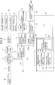
- FIG. 2 shows the overall configuration of a construction machine drive system that drives the construction machine shown in FIG. 1 .
- the drive system includes an engine 1, an assist electric motor 2, a hydraulic pump 3, a control valve 4, the bucket cylinder 5, the arm cylinder 6, the boom cylinder 7, the travel hydraulic motor 8, electrical power converters 9, 10, 13, a swing electric motor 11, the swing mechanism 12, an electrical storage device 14, a charging device 15, accessory loads 16, and a control device 17.
- the rotation speed of the engine 1 is controlled in accordance with a target rotation speed that is set by the operator.
- the engine 1 is mechanically coupled to the assist electric motor 2.
- the accessory loads 16 such as a fan and an air-conditioner compressor, are mechanically coupled to the engine 1 and connected to the assist electric motor 2 through the engine 1.
- the hydraulic pump 3 is connected to the assist electric motor 2, which is mechanically coupled to the engine 1.
- the hydraulic pump 3 is driven by the motive power of the engine 1 and of the assist electric motor 2 to supply a hydraulic fluid to the control valve 4.
- the control valve 4 controls the hydraulic fluid to be supplied to the bucket cylinder 5, the arm cylinder 6, the boom cylinder 7, and the travel hydraulic motor 8.
- the assist electric motor 2 assists the engine 1 so that the motive power of the engine 1 and of the assist electric motor 2 drives the hydraulic pump 3 and the accessory loads 16.
- the assist electric motor 2 allows the engine 1 to generate electrical power.
- Hydraulic work devices namely, the bucket cylinder 5, the arm cylinder 6, the boom cylinder 7, and the travel hydraulic motor 8, are mounted on the swing structure 202 and on the travel structure 201.
- the first electrical power converter 9 is connected to the assist electric motor 2 to convert a DC voltage to an AC voltage and convert an AC voltage to a DC voltage. In other words, the AC voltage generated by the assist electric motor 2 is converted to a DC voltage through the first electrical power converter 9.
- the second electrical power converter 10 is connected to the DC side of the first electrical power converter 9.
- the second electrical power converter 10 converts a DC voltage to an AC voltage and converts an AC voltage to a DC voltage.
- the swing electric motor 11 is connected to the AC side of the second electrical power converter 10.
- the rotation speed and torque of the swing electric motor 11 can be controlled through the first and second electrical power converters 9, 10 in accordance with information about the control lever operated by the operator.
- the swing mechanism 12 is connected to the swing electric motor 11 and driven through the swing electric motor 11.
- the first and second electrical power converters 9, 10 are interconnected through a DC bus 91A.
- the third electrical power converter 13 is connected to the DC bus 91A through a DC bus 91B.
- the voltages of the DC buses 91A, 91B are converted by the third electrical power converter 13.
- the electrical storage device 14 is connected to a side from which a DC current obtained by voltage conversion is output.
- a lead storage battery may be used as the electrical storage device 14.
- the electrical storage device 14 is connected to the charging device 15.
- the charging device 15 is connectable to an external power source EPS.
- the charging device 15 can receive an electrical current from the external power source EPS, convert it from AC to DC, and convert it to a voltage that can be used to charge the electrical storage device 14. It means that the electrical storage device 14 can be charged from the external power source EPS.
- a commercial external power source available at a low energy cost can be used to charge the electrical storage device 14 during rest time during which no work is performed. If, for instance, work is conducted during daytime but no work is conducted during nighttime, it is conceivable that the electrical storage device 14 may be charged during nighttime by connecting it to the external power source EPS, and that the electrical power stored in electrical storage device 14 may be used for daytime work. Hence, if the power required for work exceeds an engine power by a short period of time, additional power can be supplied from the electrical storage device 14. Therefore, it is demanded that the engine 1 be able to provide an engine power appropriate for average work power. Consequently, an engine having a small capacity can be used. Small-capacity engines are available at a low price and highly efficient under normal conditions. As a result, it is expected that cost reduction is achievable.
- the control device 17 is connected through communication means to the engine 1, the first electrical power converter 9, the second electrical power converter 10, the third electrical power converter 13, the electrical storage device 14, and the charging device 15.
- the control device 17 includes a mechanical load computation section 101, a work time computation section 102, and a charge/discharge control section 103.
- An engine power PE is input from the engine 1 to the control device 17 through the communication means.
- An assist electric motor mechanical power PA is input from the first electrical power converter 9 to the control device 17 through the communication means.
- a swing electric motor mechanical power PS, a charge amount Q of the electrical storage device 14, and charge information CI about the charging device 15 are input from the second electrical power converter 10 to the control device 17 through the communication means.
- the control device 17 outputs a computed charge/discharge command PB* to the third electrical power converter 13.
- the third electrical power converter 13 controls the charge/discharge amount PB of the electrical storage device 14 until it agrees with the charge/discharge command PB* output from the control device 17 by performing mutual electrical power conversion between the DC bus 91B and the electrical storage device 14.
- the charge/discharge of the electrical storage device 14 is controllable. If the charge/discharge command PB* is a positive value, it discharges the electrical storage device 14. If, on the other hand, the charge/discharge command PB* is a negative value, it charges the electrical storage device 14.
- the engine power PE and the assist electric motor mechanical power PA are input to the mechanical load computation section 101.
- the mechanical load computation section 101 uses Equation (1) to compute a mechanical load PM that corresponds to a load handled by the hydraulic pump 3 and the accessory loads 16.
- PM PE + PA
- the work time computation section 102 computes the work time T of the construction machine by adding the charge information CI derived from the charging device 15 to the time at which the construction machine is activated.
- the work time T is reset when the electrical storage device 14 is fully charged from the external power source EPS.
- the swing electric motor mechanical power PS, the mechanical load PM, the work time T, and the charge amount Q of the electrical storage device 14 are input to the charge/discharge control section 103.
- the charge/discharge control section 103 then outputs the charge/discharge command PB* to the third electrical power converter 13.
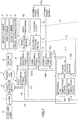
- the charge/discharge control section 103 includes a charge amount target value computation section 301, subtractors 302, 310, a first charge/discharge target value computation section 303, minimum value computing units 304, 312, a second charge/discharge target value computation section 305, a third charge/discharge target value computation section 306, adders 307, 308, 309, and a maximum value computing unit 311.
- the charge amount target value computation section 301 computes a charge amount target value Q* in accordance with the work time T of the construction machine and with predefined estimated work time Ts.
- the charge amount target value Q* is preset to the maximum charge amount Qmax of the electrical storage device 14 when the work time T is zero and preset to the minimum charge amount Qmin when the work time T represents the end of work.
- the charge amount target value Q* monotonically decreases with the work time T.
- the electrical power stored in the electrical storage device can be systematically used. This makes it possible to prevent a failure to provide assist due to an insufficient amount of electrical charge during work and prevent a failure to sufficiently reduce the amount of fuel consumption due to incomplete use of stored electrical charge at the end of work.
- the electrical storage device can be not only efficiently used, but also reduced in size.
- the estimated work time Ts is eight hours, which is regarded as average work time. However, when common work time is taken into consideration, it is appropriate that the estimated work time Ts be set within a range of 6 to 10 hours. Further, work time setup means 321 may be provided to permit the operator to set appropriate estimated work time Ts as desired. If the estimated work time Ts is set before the beginning of work, the characteristics of the charge amount target value computation section 301 are changed in accordance with the work time so that the charge amount target value Q* agrees with the minimum charge amount Qmin after the elapse of the estimated work time Ts.
- the characteristics of the charge amount target value computation section 301 are changed in accordance with elapsed time and remaining work time so that the charge amount target value Q* for the set work time Ts agrees with the minimum charge amount Qmin.
- the operator sets the work time
- the remaining work time can also be set.
- a clock function and work end time setup means which allows the operator to set the work end time are provided instead of the work time setup means, the same functionality can be implemented by computing the work time from the time and the work end time.
- the employed configuration may be such that the work end time can be changed during work.
- the adder 302 subtracts the charge amount target value Q* from the charge amount Q of the electrical storage device 14 to compute a charge amount allowance value ⁇ Q for the purpose of exercising control to ensure that the charge amount Q of the electrical storage device 14 agrees with the characteristics of the charge amount target value Q*.
- the first charge/discharge target value computation section 303 receives the input of the charge amount allowance value ⁇ Q from the adder 302 to compute a first charge/discharge target value PB1.
- the first charge/discharge target value PB1 represents a discharge amount based on the charge amount allowance value ⁇ Q.
- the charge amount allowance value ⁇ Q is smaller than 0 (zero)
- the first charge/discharge target value PB1 is 0 (zero).
- the first charge/discharge target value PB1 causes a discharge so that the charge amount Q agrees with the charge amount target value Q*.
- the minimum value computing section 304 receives the input of the computed first charge/discharge target value PB1 and the swing electric motor mechanical power PS, and outputs the smaller of these two values as a second charge/discharge target value PB2. In other words, the minimum value computing section 304 outputs a value that is obtained when the swing electric motor mechanical power PS is an upper-limit value.
- the second charge/discharge target value computation section 305 computes a third charge/discharge target value PB3 in accordance with the charge amount allowance value ⁇ Q.
- the third charge/discharge target value PB3 is 0 (zero) when the charge amount allowance value ⁇ Q is smaller than a predetermined first charge amount allowance setting Qa.
- the third charge/discharge target value PB3 is a discharge target value for causing a discharge so that the charge amount Q is equal to Q* + Qa, which represents a value greater than the charge amount target value Q*.
- the third charge/discharge target value computation section 306 computes a fourth charge/discharge target value PB4 in accordance with the charge amount allowance value ⁇ Q.
- the fourth charge/discharge target value PB4 is 0 (zero) when the charge amount allowance value ⁇ Q is greater than a predetermined second charge amount allowance setting -Qc.
- the fourth charge/discharge target value PB4 is a charge target value for causing a charge so that the charge amount Q is equal to Q* - Qc, which represents a value smaller than the charge amount target value Q*.
- the above calculated sum is then input to the adder 308, added to the second charge/discharge target value PB2 to obtain a fifth charge/discharge target value PB5.
- the adder 309 receives the input of the mechanical load PM and the swing electric motor mechanical power PS, adds these two values together, and outputs the resulting sum as a total power Pload, which represents the power required for the entire drive system.
- the subtractor 310 computes an engine power shortage amount ⁇ P by subtracting the maximum power PEmax of the engine from the total power Pload calculated by the adder 309. If the engine power shortage amount ⁇ P is a positive value, the maximum power PEmax of the engine is not sufficient for the total power Pload. If, on the other hand, the engine power shortage amount ⁇ P is a negative value, it means that the engine's maximum power is more than necessary.
- the engine power shortage amount ⁇ P and the fifth charge/discharge target value PB5, which are computed as described above, are input to the maximum value computing unit 311.
- the maximum value computing unit 311 outputs the greater of these two values. In other words, the maximum value computing unit 311 outputs a value that is obtained when the engine power shortage amount ⁇ P is a lower-limit value.
- the minimum value computing unit 312 receives the value output from the maximum value computing unit 311 and the total power Pload, and outputs the smaller of these two values as the charge/discharge amount PB. In other words, a value obtained when the total power Pload is an upper-limit value is output as the charge/discharge command PB*.
- the fifth charge/discharge target value PB5 is used to output the charge/discharge command PB*, which is obtained when the engine power shortage amount ⁇ P is a lower-limit value and the total power Pload is an upper-limit value, through the maximum value computing unit 311 and the minimum value computing unit 312.
- the charge/discharge command PB* is then input to the third electrical power converter 13.
- the third electrical power converter 13 is connected to the electrical storage device 14. Therefore, the third electrical power converter 13 can charge or discharge the electrical storage device 14 through the third electrical power converter in compliance with the input charge/discharge command.
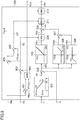
- FIG. 9 shows a system status with respect to the total power Pload and the charge/discharge amount PB.
- Region A is a region where the charge/discharge amount PB is excessive and excessive power results even when the engine power PE is 0 (zero).
- Region B is a region where the charge/discharge amount is insufficient and the total power Pload cannot be obtained even when the engine power PE is the engine's maximum power PEmax.
- Region C is a region where the charge/discharge amount is insufficient and excessive power is obtained even when the engine power PE is 0 (zero).
- Region D is a region where the charge/discharge amount PB is excessive and the total power Pload and the charge amount cannot be obtained even when the engine power PE is the engine's maximum power PEmax.
- the charge/discharge command PB* is limited as described earlier.
- the engine power PE is in balance with the assist electric motor mechanical power PA and with the mechanical load PM.
- the rotation speed of the engine 1 temporarily decreases; however, the rotation speed of the engine 1 is controlled to satisfy Equation (1) so that the engine power PE increases until the amount of increase in the mechanical load PM is in balance with the amount of increase in the engine power PE. Therefore, the engine power PE satisfies Equation (2) except for a short transient period.
- the mechanical load PM increases or decreases when the operator manipulates the control lever, an appropriate engine power PE is generated.
- the assist electric motor mechanical power PA increases or decreases.
- the first electrical power converter 9 controls the voltage of the DC bus 91A between the first electrical power converter 9 and the second electrical power converter 10. Therefore, control is exercised so that the assist electric motor mechanical power PA is in balance with the swing electric motor mechanical power PS and with the charge/discharge amount PB.
- the assist electric motor mechanical power PA decreases due to voltage control exercised by the first electrical power converter 9.
- an assist amount decreases to decrease the power supplied from the DC bus to a mechanical system.
- the assist electric motor mechanical power PA is calculated from Equation (3) except for a short transient period. In other words, even when the swing electric motor mechanical power PS increases or decreases due to a swing operation, the assist electric motor mechanical power PA is adjusted accordingly.
- FIG. 6 is a timing diagram illustrating the relationship of the charge amount target value Q*, the charge amount Q, the mechanical load PM, the swing electric motor mechanical power PS, and the charge/discharge amount PB to time.
- the initial values of the charge amount Q and the work time T are the maximum charge amount Qmax and 0 (zero), respectively.
- the mechanical load PM and the swing electric motor mechanical power PS are output as shown in the figure when the operator manipulates the control lever.
- the charge amount target value Q* calculated by the charge amount target value computation section 301 agrees with the maximum charge amount Qmax. Therefore, the charge amount allowance value ⁇ Q, which is the difference between the charge amount target value Q* and the charge amount Q, is 0 (zero).
- the first charge/discharge target value PB1, the third charge/discharge target value PB3, and the fourth charge/discharge target value PB4 are 0 (zero).
- the swing electric motor mechanical power PS is 0 (zero)
- the second charge/discharge target value PB2 is 0 (zero)
- the fifth charge/discharge target value PB5 is also 0 (zero).
- the mechanical load PM is higher than the engine's maximum power PEmax, that is, the total power Pload is higher than the engine's maximum power PEmax. Therefore, the engine power shortage amount ⁇ P, which is a lower-limit value of the charge/discharge command PB*, is a positive value. Thus, the charge/discharge command PB* is the engine power shortage amount ⁇ P. Hence, the electrical storage device 14 can be discharged to compensate for the shortage of the engine's maximum power PEmax relative to the mechanical load PM.
- the charge amount allowance value ⁇ Q is a negative value and the fifth charge/discharge target value PB5 is 0 (zero) or a negative value.
- the charge/discharge command PB* represents the engine power shortage amount ⁇ P.
- the mechanical load PM decreases to accelerate the swing electric motor 11, which has been stopped, thereby gradually increasing the swing electric motor mechanical power PS.
- the charge amount Q is smaller than Q* - Qc. Therefore, the charge amount allowance value ⁇ Q is smaller than -Qc.
- the fourth charge/discharge target value PB4 and the fifth charge/discharge target value PB5 are negative values (charging) so that the charge amount allowance value ⁇ Q is equal to Q* - Qc.
- the engine power shortage amount ⁇ P is a negative value because the total power Pload is lower than the engine's maximum power PEmax due to a decrease in the mechanical load PM.
- the fifth charge/discharge target value PB5 is output as is as the charge/discharge command PB*.
- the electrical storage device 14 is then charged so that the charge amount Q, which has been excessively decreased, is equal to Q* - Qc.
- the electrical storage device 14 is charged as needed to control the charge amount Q until it is equal to Q* - Qc, which is in a neighborhood of the charge amount target value Q*.
- the swing electric motor 11 switches to decelerate so that the swing electric motor mechanical power PS changes to a negative value (regeneration). Subsequently, the speed of the swing electric motor 11 begins to decrease.
- the second charge/discharge target value PB2 is limited by the swing electric motor mechanical power PS so that the swing electric motor mechanical power PS is a negative value (charging).
- the charge/discharge command PB* also represents the swing electric motor mechanical power PS. Further, even when the charge amount Q is larger than Q* - Qc so that the fourth charge/discharge target value PB4 is 0 (zero), a charge is continuously performed in accordance with the second charge/discharge target value PB2. This ensures that the electrical power regenerated by the swing electric motor 11 can be charged into the electrical storage device 14.
- the mechanical load PM increases without exceeding the engine's maximum power PEmax.
- the charge amount Q is between Q* - Qc and Q* and the charge amount allowance value ⁇ Q is between -Qc and 0 (zero)
- the first charge/discharge target value PB1, the third charge/discharge target value PB3, and the fourth charge/discharge target value PB4 are 0 (zero).
- the swing electric motor mechanical power PS is 0 (zero)
- the second charge/discharge target value PB2 is 0 (zero).
- the fifth charge/discharge target value PB5 is 0 (zero).
- the charge/discharge command PB* is 0 (zero) without being limited.
- the charge amount Q remains unchanged.
- the mechanical load PM decreases to increase the swing electric motor mechanical power PS, as is the case with time t1.
- the charge amount allowance value ⁇ Q is not smaller than 0 (zero). This causes the first charge/discharge target value PB1 to be a positive value (discharging).
- the charge/discharge command PB* then becomes a positive value (discharging) while the swing electric motor mechanical power PS is used as an upper limit.
- the electrical storage device 14 is discharged so that the charge amount Q agrees with the charge amount target value Q*.
- the swing electric motor mechanical power PS changes to a negative value (regeneration), as is the case with time t2.
- the charge/discharge command PB* then becomes a negative value (charging), as is the case with time t2.
- an operation is performed to charge the electrical storage device 14 with the electrical power regenerated by the swing electric motor 11.
- the mechanical load PM increases without exceeding the engine's maximum power PEmax until the swing electric motor mechanical power PS is 0 (zero), as is the case with time t3.
- the second charge/discharge target value PB2 is 0 (zero).
- the charge amount allowance value ⁇ Q is not smaller than Qa so that the third charge/discharge target value PB3 is a positive value (discharging).
- the charge/discharge command PB* is a positive value (discharging).
- the electrical storage device 14 is discharged so that the charge amount Q is equal to Q* + Qa.
- the mechanical load PM decreases to increase the swing electric motor mechanical power PS, as is the case with time t1.
- the charge amount allowance value ⁇ Q is not smaller than Qa.
- the third charge/discharge target value PB3 is a positive value (discharging) and the first charge/discharge target value PB1 is also a positive value (discharging)
- the second charge/discharge target value PB2 which is limited by the swing electric motor mechanical power PS, is also a positive value (discharging).
- the charge/discharge command PB* is a positive value (discharging) greater than the swing electric motor mechanical power PS.
- the electrical storage device 14 is discharged. In this instance, the amount of discharged electrical power is larger than used by the swing electric motor 11. As the discharged electrical power is higher than the swing electric motor mechanical power PS, the assist electric motor 2 assists the engine 1 through the first electrical power converter 9.
- the third charge/discharge target value PB3 is 0 (zero).
- the charge/discharge command PB* agrees with the swing electric motor mechanical power PS.
- the amount of electrical power used by the swing electric motor 11 is discharged from the electrical storage device 14.
- the swing electric motor mechanical power PS exceeds the first charge/discharge target value PB1 due to an increase in the swing electric motor mechanical power PS
- the first charge/discharge target value PB1 is output as the charge/discharge command PB*.
- the electrical storage device 14 is discharged so that the charge amount Q agrees with the charge amount target value Q*.
- the swing electric motor mechanical power PS switches to a negative value (regeneration), as is the case with time t5
- the charge/discharge command PB* is a negative value (charging), as is the case with time t5.
- an operation is performed to charge the electrical storage device 14 with the electrical power regenerated by the swing electric motor 11.
- the third charge/discharge target value PB3 is a positive value so that the charge/discharge command PB* is higher than the swing electric motor mechanical power PS. This ensures that part of the electrical power regenerated by the swing electric motor 11 is not charged into the electrical storage device 14. This part of the electrical power, which is not used to charge the electrical storage device 14, is supplied to the assist electric motor 2 through the first electrical power converter 9 to assist the engine 1.
- the swing electric motor mechanical power PS is a negative value so that the swing electric motor 11 regenerates electrical power
- the regenerative electrical power is basically charged into the electrical storage device 14 as indicated by the operation performed at time t2 to time t3.
- the operation performed relative to the charge amount Q is described below. If the charge amount Q is not larger than Q* - Qc, the charge amount is significantly insufficient relative to the charge amount target value Q*. Therefore, it is necessary to perform a charge operation in order to obtain electrical power required for an operation whose total power Pload is higher than the engine's maximum power PEmax. Consequently, control is exercised as indicated by the operation performed at time t1 to time t2 so that the charge amount Q is equal to Q* - Qc.
- a wait is performed without conducting a charge/discharge operation as indicated by the operation performed at time t3 to time t4 until the charge amount target value Q* decreases with time except when the aforementioned engine power shortage amount is positive or when regenerative electrical power is generated. If the charge amount Q is between Q* and Q* + Qa and if the amount of fuel consumption by the engine 1 is significantly decreased by discharging the electrical storage device 14, it is preferred that a discharge operation be performed.
- FIG. 4 shows a case where the charge/discharge command PB* is higher than the swing electric motor mechanical power PS.
- the assist electric motor 2 performs a power running operation and the electrical storage device 14 is discharged to provide assist and cover energy shortage.
- FIG. 5 shows a case where the charge/discharge command PB* is lower than the swing electric motor mechanical power PS.
- the assist electric motor 2 performs a regeneration operation.
- the electrical power discharged from the electrical storage section 14 drives the hydraulic pump 3 through the third electrical power converter 13, the first electrical power converter 9, and the assist electric motor 2.
- the engine 1 directly drives the hydraulic pump 3 through the assist electric motor 2. If device efficiency is taken into consideration, the number of intervening devices is large when the electrical power discharged from the electrical storage device 14 is used to drive the hydraulic pump 3. This increases the conversion loss in electrical power or in motive power. Therefore, the power of the engine needs to be increased to compensate for the conversion loss. As a result, the effect of reducing the amount of fuel consumption by the engine is diminished.
- the power flows shown in FIG. 5 relate to a case where the electrical storage device 14 supplies electrical power to the swing electric motor 11 through the third electrical power converter 13 and the second electrical power converter 10 or relate to a case where the engine 1 supplies electrical power to the swing electric motor 11 through the assist electric motor 2, the first electrical power converter 9, and the second electrical power converter 10.
- the number of intervening devices is small when the electrical power discharged from the electrical storage device 14 is supplied to the swing electric motor 11. Further, the conversion loss in electrical power or in motive power is insignificant. Therefore, the power of the engine does not need to be increased to compensate for the conversion loss. As a result, the effect of reducing the amount of fuel consumption by the engine is great.
- setup change means may be provided to let the operator manipulate, for instance, a control button to change the estimated work time setting Ts.
- the setup change means is preferably provided in the cab 206 so that it can be manipulated by the operator.
- the estimated work time input by the operator is input to the control device 17 or preferably the charge amount target value computation section 301 of the charge/discharge control section 103 through the communication means. Therefore, even when the estimated work time is changed, the electrical storage device can be systematically used in accordance with the changed estimated work time. This makes it possible to prevent a failure to effectively use an available charge amount when the work time is short and prevent a failure to obtain a charge amount necessary for providing assist when the work time is long.
- an operation can be performed without decreasing the charge amount of the electrical storage device by providing a setup change button or other setup change means 341 for permitting the operator to specify whether or not to perform a charge and switching to a fixed charge amount target value Q*.
- the setup change means 341 for specifying whether or not to perform a charge is preferably provided in the cab 206 so that it can be manipulated by the operator.
- Information input by the operator to specify whether or not to perform a charge is input to the control device 17 through the communication means. In this case, too, it is possible to perform a discharge in order to provide assist when the engine power is insufficient and charge the electrical power regenerated by the swing electric motor 11 into the electrical storage device for reuse.
- the amount of fuel consumption can be reduced. Further, if the rest time is longer than a predetermined period of time and no charge has been performed by using an external power source in a situation where no setup means is available to the operator, it can be concluded that the current environment does not permit the use of the external power source to charge the electrical storage device. In this instance, an operation can be performed without decreasing the charge amount of the electrical storage device by switching to a fixed charge amount target value Q* in the same manner as described above.
- FIGS. 7 and 8 A second embodiment of the present invention will now be described with reference to FIGS. 7 and 8 .
- the following description is given without considering device efficiency in order to provide better understanding of the second embodiment.
- Like elements in the first and second embodiments are designated by the same reference signs and will not be redundantly described.
- FIG. 7 shows the overall configuration of the drive system for the construction machine.
- the drive system according to the second embodiment differs from the drive system shown in FIG. 1 in that a fourth electrical power converter 701 is added and that a control device 717 is included in place of the control device 17.
- the fourth electrical power converter 701, the first electrical power converter 9, and the second electrical power converter 10 are interconnected through the DC buses 91A, 91B, which are DC side circuits, to convert the voltage of electrical power supplied from the external power source EPS.
- the electrical power supplied from the external power source EPS is forwarded through the fourth electrical power converter 701 and supplied to various sections through the DC buses 91A, 91B in compliance with a constant power feed command PC*.
- the capacity of the supplied electrical power is smaller than the maximum power PEmax of the engine 1.
- the control device 717 includes a charge/discharge control section 703 instead of the charge/discharge control section 103, which is included in the control device 17 shown in FIG. 1 .
- the charge/discharge control section 703 receives the input of the swing electric motor mechanical power PS, mechanical load PM, and work time T, receives the input of the charge amount Q from the electrical storage device 14, outputs the charge/discharge command PB* to the third electrical power converter 13, and outputs the constant power feed command PC* to the fourth electrical power converter 701.
- the charge/discharge control section 703 differs from the charge/discharge control section 103 shown in FIG. 3 in that an adder-subtractor 801, a minimum value computing unit 802, and a subtractor 803 are added.
- the adder-subtractor 801 subtracts the fourth charge/discharge target value PB4 from the sum of the mechanical load PM and the swing electric motor mechanical power PS.
- the minimum value computing unit 802 compares the value calculated by the adder-subtractor 801 to a maximum constant power feed amount PCmax of the fourth electrical power converter 701 and outputs the smaller of these two values as the constant power feed command PC*.
- a portion equivalent to a power requested by the system can be supplied from the external power source when the power requested by the system is smaller than the maximum constant power feed amount PCmax.
- the constant power feed command PC* can be supplied from the external power source when the power requested by the system is larger than the maximum constant power feed amount PCmax.
- the subtractor 803 subtracts the constant power feed command PC* from the swing electric motor mechanical power PS and outputs a corrected swing electric motor mechanical power PS', which is to be used in place of the swing electric motor mechanical power PS of the charge/discharge control section 103.
- the reason is that the electrical power supplied from the fourth electrical power converter 701 is equivalent in terms of a DC bus load to the swing electric motor mechanical power PS minus the supplied electrical power. This makes it necessary for the subtractor 803 to consider the electrical power supplied from the fourth electrical power converter 701.
- the drive system for the construction machine according to the second embodiment is equivalent to a system in which the electrical power consumption of the swing electric motor 11 is decreased by the amount of supplied electrical power when the swing electric motor 11 is performing a power running operation and the regenerative electrical power of the swing electric motor 11 is increased by the amount of supplied electrical power when the swing electric motor 11 is performing a regeneration operation. Therefore, the second embodiment provides the same charge/discharge control of the electrical storage device 14 and the same advantages as the first embodiment.
- the second embodiment also provides an advantage of being capable of reducing the fuel consumption of the engine by allowing external electrical power to be supplied within the range of a power requested by the system. Further, as an engine is incorporated, it is possible to not only use a small-capacity electrical power converter as the fourth electrical power converter 701, but also perform an operation even when an external power feed is not provided. Description of Reference Symbols
Landscapes
- Engineering & Computer Science (AREA)
- Power Engineering (AREA)
- Mechanical Engineering (AREA)
- Transportation (AREA)
- General Engineering & Computer Science (AREA)
- Structural Engineering (AREA)
- Civil Engineering (AREA)
- Mining & Mineral Resources (AREA)
- Chemical & Material Sciences (AREA)
- Combustion & Propulsion (AREA)
- Life Sciences & Earth Sciences (AREA)
- Sustainable Development (AREA)
- Sustainable Energy (AREA)
- Operation Control Of Excavators (AREA)
- Hybrid Electric Vehicles (AREA)
- Electric Propulsion And Braking For Vehicles (AREA)
- Charge And Discharge Circuits For Batteries Or The Like (AREA)
Claims (9)
- Machine de chantier ayant un moteur (1), une motrice électrique auxiliaire (2) qui est coaxialement et mécaniquement connectée au moteur, et un convertisseur de puissance électrique (9, 13) qui est connecté à la motrice électrique auxiliaire (2) et à un dispositif de stockage électrique (14) afin de commander la tension de la motrice électrique auxiliaire (2) et la tension du dispositif de stockage électrique (14), la machine de chantier comprenant :un moyen de commande de charge/décharge (103) destiné à commander une quantité de charge/décharge en accord avec une valeur cible de quantité de charge (Q*), la valeur cible de quantité de charge (Q*) étant définie pour être égale à une quantité de charge minimum (Qmin) du dispositif de stockage électrique à la fin du travail,caractérisée en ce que la machine de chantier comprend en outre :un dispositif de chargement (15) connecté au dispositif de stockage électrique (14), le dispositif de stockage électrique (14) étant capable de devenir chargé au moyen du dispositif de chargement (15) à partir d'une source de puissance externe (EPS) ; etdans laquelle le moyen de commande de charge/décharge (103) inclut une section de calcul de valeur cible de quantité de charge (301) qui calcule la valeur cible de quantité de charge (Q*) pour le dispositif de stockage électrique (14) en accord avec le temps de travail (T) de la machine de chantier et avec le temps de travail estimé prédéfini (Ts), et une section de calcul de valeur cible de charge/décharge (305, 306) qui décharge le dispositif de stockage électrique (14) quand une quantité de charge (Q) du dispositif de stockage électrique (14) est plus grande qu'une quantité de charge (Q* + Qa) déterminée en accord avec la valeur cible de quantité de charge (Q*) et avec une valeur prédéterminée (Qa), et qui charge le dispositif de stockage électrique (14) quand le quantité de charge (Q) du dispositif de stockage électrique (14) est plus petite qu'une quantité de charge (Q* - Qc) déterminée en accord avec la valeur cible de quantité de charge (Q*) et avec une valeur prédéterminée (Qc).
- Machine de chantier selon la revendication 1, comprenant en outre :
un moyen d'alimentation de puissance externe (701, 717) destiné à recevoir une puissance électrique à partir de la source de puissance externe (EPS) et à distribuer la puissance électrique vers un circuit côté courant continu (CC) (91A, 791B) du convertisseur de puissance électrique (9). - Machine de chantier selon la revendication 1,
dans laquelle la section de calcul de valeur cible de charge/décharge (303, 304, 305, 306) amène le dispositif de stockage électrique (14) à décharger une puissance électrique plus petite que la consommation de puissance (PS) d'un dispositif électriquement entraîné de la machine de chantier quand la quantité de charge (Q) du dispositif de stockage électrique (14) est plus grande que la valeur cible de quantité de charge (Q*) - Machine de chantier selon la revendication 1, comprenant en outre :
un moyen de réglage (321) capable de régler le temps de travail estimé (Ts). - Machine de chantier selon la revendication 1, dans laquelle le temps de travail estimé (Ts) est six à dix heures.
- Machine de chantier selon la revendication 1 ou 2, comprenant en outre :un moyen de réglage (341) destiné à sélectionner un mode qui spécifie s'il s'agit ou non d'exécuter une charge à partir de la source de puissance externe (EPS) ;dans laquelle un procédé d'exercice d'une commande de charge/décharge sur le dispositif de stockage électrique (14) change en accord avec le mode sélectionné.
- Machine de chantier selon la revendication 1 ou 3, comprenant en outre :un moyen de réglage (341) destiné à sélectionner un mode qui spécifie s'il s'agit ou non d'exécuter une charge depuis la source de puissance externe (EPS) ;dans laquelle la valeur cible de quantité de charge (Q*) change en accord avec le mode sélectionné.
- Machine de chantier selon la revendication 5 ou 6, dans laquelle, quand une période temporelle prédéfinie s'écoule après que la machine de chantier s'arrête de fonctionner et que la machine de chantier démarre alors que le dispositif de stockage électrique (14) n'est pas en train d'être chargé par la source de puissance externe (EPS), la machine de chantier commute vers un mode dans lequel la source de puissance externe (EPS) n'exécute pas une charge.
- Machine de chantier selon la revendication 1, dans laquelle la valeur cible de quantité de charge (Q*) est définie pour être égale à une quantité de charge maximum (Qmax) du dispositif de stockage électrique au début du travail, et pour être égale à la quantité de charge minimum (Qmin) du dispositif de stockage électrique à la fin du travail.
Applications Claiming Priority (2)
| Application Number | Priority Date | Filing Date | Title |
|---|---|---|---|
| JP2010232075 | 2010-10-15 | ||
| PCT/JP2011/073435 WO2012050133A1 (fr) | 2010-10-15 | 2011-10-12 | Machine de construction |
Publications (3)
| Publication Number | Publication Date |
|---|---|
| EP2628859A1 EP2628859A1 (fr) | 2013-08-21 |
| EP2628859A4 EP2628859A4 (fr) | 2018-02-14 |
| EP2628859B1 true EP2628859B1 (fr) | 2019-07-03 |
Family
ID=45938360
Family Applications (1)
| Application Number | Title | Priority Date | Filing Date |
|---|---|---|---|
| EP11832567.9A Not-in-force EP2628859B1 (fr) | 2010-10-15 | 2011-10-12 | Machine de construction |
Country Status (6)
| Country | Link |
|---|---|
| US (1) | US9421873B2 (fr) |
| EP (1) | EP2628859B1 (fr) |
| JP (1) | JP5605815B2 (fr) |
| KR (1) | KR101834592B1 (fr) |
| CN (1) | CN103189576B (fr) |
| WO (1) | WO2012050133A1 (fr) |
Families Citing this family (8)
| Publication number | Priority date | Publication date | Assignee | Title |
|---|---|---|---|---|
| JP5226733B2 (ja) * | 2010-05-20 | 2013-07-03 | 株式会社小松製作所 | ハイブリッド建設機械およびハイブリッド建設機械の蓄電器容量計測方法 |
| SE542381C2 (sv) | 2012-04-23 | 2020-04-21 | Brokk Ab | Elektiskt driven demoleringsrobot och dess kraftförsörjningssystem |
| JP6162969B2 (ja) * | 2013-02-04 | 2017-07-12 | 日立建機株式会社 | 作業機械 |
| JP6403386B2 (ja) * | 2014-01-15 | 2018-10-10 | 株式会社小松製作所 | 作業車両及び作業車両の制御方法 |
| US9719498B2 (en) * | 2015-05-29 | 2017-08-01 | Caterpillar Inc. | System and method for recovering energy in a machine |
| JP6381491B2 (ja) * | 2015-07-07 | 2018-08-29 | 日立建機株式会社 | 建設機械の制御装置 |
| KR102330256B1 (ko) * | 2019-11-29 | 2021-11-24 | 주식회사 이스쿠스 | 가변 부하용 이중 전원식 전기동력 공급 시스템 |
| US12442339B2 (en) * | 2021-08-02 | 2025-10-14 | Transportation Ip Holdings, Llc | Electric drive system for a vehicle |
Family Cites Families (18)
| Publication number | Priority date | Publication date | Assignee | Title |
|---|---|---|---|---|
| JPH07212902A (ja) * | 1993-12-02 | 1995-08-11 | Nippondenso Co Ltd | 電気自動車の空調装置制御システム |
| US6172480B1 (en) * | 1998-10-23 | 2001-01-09 | Primetech Electronics, Inc. | Compact fast battery charger |
| JP2001011901A (ja) | 1999-06-30 | 2001-01-16 | Kobe Steel Ltd | ハイブリッド建設機械の作業情報処理装置 |
| JP3859982B2 (ja) * | 2001-04-27 | 2006-12-20 | 株式会社神戸製鋼所 | ハイブリッド建設機械の電力制御装置 |
| JP2004150304A (ja) * | 2002-10-29 | 2004-05-27 | Komatsu Ltd | エンジンの制御装置 |
| JP4529866B2 (ja) | 2005-10-27 | 2010-08-25 | コベルコ建機株式会社 | ハイブリッド式建設機械 |
| JP5096813B2 (ja) * | 2007-07-03 | 2012-12-12 | 日立建機株式会社 | 建設機械のエンジン制御装置 |
| JP5269811B2 (ja) * | 2007-12-26 | 2013-08-21 | 住友重機械工業株式会社 | ハイブリッド型建設機械及びハイブリッド型建設機械の制御方法 |
| JP2009197514A (ja) * | 2008-02-22 | 2009-09-03 | Hitachi Constr Mach Co Ltd | 電気駆動式作業機械 |
| JP5004834B2 (ja) * | 2008-03-13 | 2012-08-22 | 日立建機株式会社 | 作業機械 |
| KR101169962B1 (ko) * | 2008-04-11 | 2012-08-06 | 스미토모 겐키 가부시키가이샤 | 작업기계 |
| US20100028684A1 (en) | 2008-07-31 | 2010-02-04 | Jose Mariscal | Conductive multilayer stack |
| JP5319236B2 (ja) * | 2008-10-22 | 2013-10-16 | 日立建機株式会社 | 電源装置および作業機械 |
| CN102209655B (zh) * | 2008-11-10 | 2015-05-06 | 住友重机械工业株式会社 | 混合式施工机械 |
| JP5097687B2 (ja) * | 2008-12-05 | 2012-12-12 | 株式会社日立製作所 | 鉄道車両及び鉄道車両用駆動装置 |
| WO2010079794A1 (fr) * | 2009-01-07 | 2010-07-15 | 住友重機械工業株式会社 | Méthode de réchauffage pour engin de génie civil hybride, et engin de génie civil hybride |
| EP2415935A4 (fr) | 2009-03-31 | 2016-09-21 | Hitachi Construction Machinery | Machine de construction et véhicule industriel muni d'un système d'alimentation électrique |
| CN102483441B (zh) * | 2009-09-03 | 2014-06-25 | 丰田自动车株式会社 | 电池组的充电状态检测装置以及充电状态检测方法 |
-
2011
- 2011-10-12 CN CN201180049640.6A patent/CN103189576B/zh not_active Expired - Fee Related
- 2011-10-12 EP EP11832567.9A patent/EP2628859B1/fr not_active Not-in-force
- 2011-10-12 KR KR1020137008833A patent/KR101834592B1/ko not_active Expired - Fee Related
- 2011-10-12 WO PCT/JP2011/073435 patent/WO2012050133A1/fr not_active Ceased
- 2011-10-12 US US13/879,444 patent/US9421873B2/en not_active Expired - Fee Related
- 2011-10-12 JP JP2012538697A patent/JP5605815B2/ja not_active Expired - Fee Related
Non-Patent Citations (1)
| Title |
|---|
| None * |
Also Published As
| Publication number | Publication date |
|---|---|
| EP2628859A4 (fr) | 2018-02-14 |
| JPWO2012050133A1 (ja) | 2014-02-24 |
| US9421873B2 (en) | 2016-08-23 |
| CN103189576B (zh) | 2016-10-12 |
| KR101834592B1 (ko) | 2018-03-05 |
| EP2628859A1 (fr) | 2013-08-21 |
| CN103189576A (zh) | 2013-07-03 |
| WO2012050133A1 (fr) | 2012-04-19 |
| JP5605815B2 (ja) | 2014-10-15 |
| KR20130132413A (ko) | 2013-12-04 |
| US20140103874A1 (en) | 2014-04-17 |
Similar Documents
| Publication | Publication Date | Title |
|---|---|---|
| EP2628859B1 (fr) | Machine de construction | |
| US9340953B2 (en) | Construction machine | |
| KR101952984B1 (ko) | 하이브리드식 건설 기계 및 그 제어 방법 | |
| US8924100B2 (en) | Hybrid construction machine | |
| EP3006745B1 (fr) | Machine de construction | |
| CN103384747B (zh) | 混合动力式工程机械 | |
| JP6325032B2 (ja) | ショベル | |
| EP3064651A1 (fr) | Engin de chantier | |
| EP2752524B1 (fr) | Engin de chantier | |
| JP2011032857A (ja) | ハイブリッド式建設機械の制御システム及び方法 | |
| JP2007071197A (ja) | ハイブリッド型油圧作業機 | |
| KR20130103305A (ko) | 하이브리드식 굴삭기의 제어시스템 | |
| JP2010173599A (ja) | ハイブリッド式作業機械の制御方法、及びサーボ制御システムの制御方法 | |
| CN103890280A (zh) | 混合动力驱动式的液压作业机械 | |
| CN103339329B (zh) | 作业机械 | |
| JP2012016993A (ja) | ハイブリッド型建設機械における制御システム | |
| JP4563302B2 (ja) | 電力配分制御装置およびハイブリッド建設機械 | |
| KR101703484B1 (ko) | 동력 제어 장치 및 이를 구비한 하이브리드 건설 기계 | |
| JP5808635B2 (ja) | ハイブリッド式ショベルの制御方法 | |
| JP2008094531A (ja) | マグネット作業機の制御装置 |
Legal Events
| Date | Code | Title | Description |
|---|---|---|---|
| PUAI | Public reference made under article 153(3) epc to a published international application that has entered the european phase |
Free format text: ORIGINAL CODE: 0009012 |
|
| 17P | Request for examination filed |
Effective date: 20130515 |
|
| AK | Designated contracting states |
Kind code of ref document: A1 Designated state(s): AL AT BE BG CH CY CZ DE DK EE ES FI FR GB GR HR HU IE IS IT LI LT LU LV MC MK MT NL NO PL PT RO RS SE SI SK SM TR |
|
| DAX | Request for extension of the european patent (deleted) | ||
| RA4 | Supplementary search report drawn up and despatched (corrected) |
Effective date: 20180117 |
|
| RIC1 | Information provided on ipc code assigned before grant |
Ipc: F02D 29/02 20060101ALI20180111BHEP Ipc: B60L 11/14 20060101ALI20180111BHEP Ipc: E02F 9/20 20060101AFI20180111BHEP |
|
| GRAJ | Information related to disapproval of communication of intention to grant by the applicant or resumption of examination proceedings by the epo deleted |
Free format text: ORIGINAL CODE: EPIDOSDIGR1 |
|
| STAA | Information on the status of an ep patent application or granted ep patent |
Free format text: STATUS: GRANT OF PATENT IS INTENDED |
|
| GRAP | Despatch of communication of intention to grant a patent |
Free format text: ORIGINAL CODE: EPIDOSNIGR1 |
|
| RIC1 | Information provided on ipc code assigned before grant |
Ipc: E02F 9/20 20060101AFI20190123BHEP Ipc: F02D 29/02 20060101ALI20190123BHEP Ipc: B60L 50/16 20190101ALI20190123BHEP |
|
| RIN1 | Information on inventor provided before grant (corrected) |
Inventor name: EDAMURA, MANABU Inventor name: ISHIDA, SEIJI Inventor name: IZUMI, SHIHO Inventor name: FUJISHIMA, KAZUO Inventor name: KAJITA, YUSUKE Inventor name: SATAKE, HIDETOSHI Inventor name: SASAKI, MASATAKA |
|
| INTG | Intention to grant announced |
Effective date: 20190225 |
|
| RIN1 | Information on inventor provided before grant (corrected) |
Inventor name: SASAKI, MASATAKA Inventor name: KAJITA, YUSUKE Inventor name: SATAKE, HIDETOSHI Inventor name: FUJISHIMA, KAZUO Inventor name: EDAMURA, MANABU Inventor name: ISHIDA, SEIJI Inventor name: IZUMI, SHIHO |
|
| GRAS | Grant fee paid |
Free format text: ORIGINAL CODE: EPIDOSNIGR3 |
|
| GRAA | (expected) grant |
Free format text: ORIGINAL CODE: 0009210 |
|
| STAA | Information on the status of an ep patent application or granted ep patent |
Free format text: STATUS: THE PATENT HAS BEEN GRANTED |
|
| RAP1 | Party data changed (applicant data changed or rights of an application transferred) |
Owner name: HITACHI CONSTRUCTION MACHINERY CO., LTD. |
|
| AK | Designated contracting states |
Kind code of ref document: B1 Designated state(s): AL AT BE BG CH CY CZ DE DK EE ES FI FR GB GR HR HU IE IS IT LI LT LU LV MC MK MT NL NO PL PT RO RS SE SI SK SM TR |
|
| REG | Reference to a national code |
Ref country code: GB Ref legal event code: FG4D |
|
| REG | Reference to a national code |
Ref country code: CH Ref legal event code: EP Ref country code: AT Ref legal event code: REF Ref document number: 1151155 Country of ref document: AT Kind code of ref document: T Effective date: 20190715 |
|
| REG | Reference to a national code |
Ref country code: IE Ref legal event code: FG4D |
|
| REG | Reference to a national code |
Ref country code: DE Ref legal event code: R096 Ref document number: 602011060258 Country of ref document: DE |
|
| REG | Reference to a national code |
Ref country code: NL Ref legal event code: MP Effective date: 20190703 |
|
| REG | Reference to a national code |
Ref country code: LT Ref legal event code: MG4D |
|
| REG | Reference to a national code |
Ref country code: AT Ref legal event code: MK05 Ref document number: 1151155 Country of ref document: AT Kind code of ref document: T Effective date: 20190703 |
|
| PG25 | Lapsed in a contracting state [announced via postgrant information from national office to epo] |
Ref country code: CZ Free format text: LAPSE BECAUSE OF FAILURE TO SUBMIT A TRANSLATION OF THE DESCRIPTION OR TO PAY THE FEE WITHIN THE PRESCRIBED TIME-LIMIT Effective date: 20190703 Ref country code: FI Free format text: LAPSE BECAUSE OF FAILURE TO SUBMIT A TRANSLATION OF THE DESCRIPTION OR TO PAY THE FEE WITHIN THE PRESCRIBED TIME-LIMIT Effective date: 20190703 Ref country code: LT Free format text: LAPSE BECAUSE OF FAILURE TO SUBMIT A TRANSLATION OF THE DESCRIPTION OR TO PAY THE FEE WITHIN THE PRESCRIBED TIME-LIMIT Effective date: 20190703 Ref country code: HR Free format text: LAPSE BECAUSE OF FAILURE TO SUBMIT A TRANSLATION OF THE DESCRIPTION OR TO PAY THE FEE WITHIN THE PRESCRIBED TIME-LIMIT Effective date: 20190703 Ref country code: NO Free format text: LAPSE BECAUSE OF FAILURE TO SUBMIT A TRANSLATION OF THE DESCRIPTION OR TO PAY THE FEE WITHIN THE PRESCRIBED TIME-LIMIT Effective date: 20191003 Ref country code: BG Free format text: LAPSE BECAUSE OF FAILURE TO SUBMIT A TRANSLATION OF THE DESCRIPTION OR TO PAY THE FEE WITHIN THE PRESCRIBED TIME-LIMIT Effective date: 20191003 Ref country code: SE Free format text: LAPSE BECAUSE OF FAILURE TO SUBMIT A TRANSLATION OF THE DESCRIPTION OR TO PAY THE FEE WITHIN THE PRESCRIBED TIME-LIMIT Effective date: 20190703 Ref country code: PT Free format text: LAPSE BECAUSE OF FAILURE TO SUBMIT A TRANSLATION OF THE DESCRIPTION OR TO PAY THE FEE WITHIN THE PRESCRIBED TIME-LIMIT Effective date: 20191104 Ref country code: NL Free format text: LAPSE BECAUSE OF FAILURE TO SUBMIT A TRANSLATION OF THE DESCRIPTION OR TO PAY THE FEE WITHIN THE PRESCRIBED TIME-LIMIT Effective date: 20190703 Ref country code: AT Free format text: LAPSE BECAUSE OF FAILURE TO SUBMIT A TRANSLATION OF THE DESCRIPTION OR TO PAY THE FEE WITHIN THE PRESCRIBED TIME-LIMIT Effective date: 20190703 |
|
| PG25 | Lapsed in a contracting state [announced via postgrant information from national office to epo] |
Ref country code: ES Free format text: LAPSE BECAUSE OF FAILURE TO SUBMIT A TRANSLATION OF THE DESCRIPTION OR TO PAY THE FEE WITHIN THE PRESCRIBED TIME-LIMIT Effective date: 20190703 Ref country code: GR Free format text: LAPSE BECAUSE OF FAILURE TO SUBMIT A TRANSLATION OF THE DESCRIPTION OR TO PAY THE FEE WITHIN THE PRESCRIBED TIME-LIMIT Effective date: 20191004 Ref country code: AL Free format text: LAPSE BECAUSE OF FAILURE TO SUBMIT A TRANSLATION OF THE DESCRIPTION OR TO PAY THE FEE WITHIN THE PRESCRIBED TIME-LIMIT Effective date: 20190703 Ref country code: LV Free format text: LAPSE BECAUSE OF FAILURE TO SUBMIT A TRANSLATION OF THE DESCRIPTION OR TO PAY THE FEE WITHIN THE PRESCRIBED TIME-LIMIT Effective date: 20190703 Ref country code: IS Free format text: LAPSE BECAUSE OF FAILURE TO SUBMIT A TRANSLATION OF THE DESCRIPTION OR TO PAY THE FEE WITHIN THE PRESCRIBED TIME-LIMIT Effective date: 20191103 Ref country code: RS Free format text: LAPSE BECAUSE OF FAILURE TO SUBMIT A TRANSLATION OF THE DESCRIPTION OR TO PAY THE FEE WITHIN THE PRESCRIBED TIME-LIMIT Effective date: 20190703 |
|
| PG25 | Lapsed in a contracting state [announced via postgrant information from national office to epo] |
Ref country code: TR Free format text: LAPSE BECAUSE OF FAILURE TO SUBMIT A TRANSLATION OF THE DESCRIPTION OR TO PAY THE FEE WITHIN THE PRESCRIBED TIME-LIMIT Effective date: 20190703 |
|
| PG25 | Lapsed in a contracting state [announced via postgrant information from national office to epo] |
Ref country code: EE Free format text: LAPSE BECAUSE OF FAILURE TO SUBMIT A TRANSLATION OF THE DESCRIPTION OR TO PAY THE FEE WITHIN THE PRESCRIBED TIME-LIMIT Effective date: 20190703 Ref country code: PL Free format text: LAPSE BECAUSE OF FAILURE TO SUBMIT A TRANSLATION OF THE DESCRIPTION OR TO PAY THE FEE WITHIN THE PRESCRIBED TIME-LIMIT Effective date: 20190703 Ref country code: IT Free format text: LAPSE BECAUSE OF FAILURE TO SUBMIT A TRANSLATION OF THE DESCRIPTION OR TO PAY THE FEE WITHIN THE PRESCRIBED TIME-LIMIT Effective date: 20190703 Ref country code: RO Free format text: LAPSE BECAUSE OF FAILURE TO SUBMIT A TRANSLATION OF THE DESCRIPTION OR TO PAY THE FEE WITHIN THE PRESCRIBED TIME-LIMIT Effective date: 20190703 Ref country code: DK Free format text: LAPSE BECAUSE OF FAILURE TO SUBMIT A TRANSLATION OF THE DESCRIPTION OR TO PAY THE FEE WITHIN THE PRESCRIBED TIME-LIMIT Effective date: 20190703 |
|
| PG25 | Lapsed in a contracting state [announced via postgrant information from national office to epo] |
Ref country code: SK Free format text: LAPSE BECAUSE OF FAILURE TO SUBMIT A TRANSLATION OF THE DESCRIPTION OR TO PAY THE FEE WITHIN THE PRESCRIBED TIME-LIMIT Effective date: 20190703 Ref country code: IS Free format text: LAPSE BECAUSE OF FAILURE TO SUBMIT A TRANSLATION OF THE DESCRIPTION OR TO PAY THE FEE WITHIN THE PRESCRIBED TIME-LIMIT Effective date: 20200224 Ref country code: SM Free format text: LAPSE BECAUSE OF FAILURE TO SUBMIT A TRANSLATION OF THE DESCRIPTION OR TO PAY THE FEE WITHIN THE PRESCRIBED TIME-LIMIT Effective date: 20190703 Ref country code: MC Free format text: LAPSE BECAUSE OF FAILURE TO SUBMIT A TRANSLATION OF THE DESCRIPTION OR TO PAY THE FEE WITHIN THE PRESCRIBED TIME-LIMIT Effective date: 20190703 |
|
| REG | Reference to a national code |
Ref country code: CH Ref legal event code: PL |
|
| REG | Reference to a national code |
Ref country code: DE Ref legal event code: R097 Ref document number: 602011060258 Country of ref document: DE |
|
| PLBE | No opposition filed within time limit |
Free format text: ORIGINAL CODE: 0009261 |
|
| STAA | Information on the status of an ep patent application or granted ep patent |
Free format text: STATUS: NO OPPOSITION FILED WITHIN TIME LIMIT |
|
| PG2D | Information on lapse in contracting state deleted |
Ref country code: IS |
|
| PG25 | Lapsed in a contracting state [announced via postgrant information from national office to epo] |
Ref country code: CH Free format text: LAPSE BECAUSE OF NON-PAYMENT OF DUE FEES Effective date: 20191031 Ref country code: LU Free format text: LAPSE BECAUSE OF NON-PAYMENT OF DUE FEES Effective date: 20191012 Ref country code: LI Free format text: LAPSE BECAUSE OF NON-PAYMENT OF DUE FEES Effective date: 20191031 |
|
| 26N | No opposition filed |
Effective date: 20200603 |
|
| REG | Reference to a national code |
Ref country code: BE Ref legal event code: MM Effective date: 20191031 |
|
| PG25 | Lapsed in a contracting state [announced via postgrant information from national office to epo] |
Ref country code: SI Free format text: LAPSE BECAUSE OF FAILURE TO SUBMIT A TRANSLATION OF THE DESCRIPTION OR TO PAY THE FEE WITHIN THE PRESCRIBED TIME-LIMIT Effective date: 20190703 Ref country code: BE Free format text: LAPSE BECAUSE OF NON-PAYMENT OF DUE FEES Effective date: 20191031 |
|
| PG25 | Lapsed in a contracting state [announced via postgrant information from national office to epo] |
Ref country code: FR Free format text: LAPSE BECAUSE OF NON-PAYMENT OF DUE FEES Effective date: 20191031 Ref country code: IE Free format text: LAPSE BECAUSE OF NON-PAYMENT OF DUE FEES Effective date: 20191012 |
|
| PG25 | Lapsed in a contracting state [announced via postgrant information from national office to epo] |
Ref country code: CY Free format text: LAPSE BECAUSE OF FAILURE TO SUBMIT A TRANSLATION OF THE DESCRIPTION OR TO PAY THE FEE WITHIN THE PRESCRIBED TIME-LIMIT Effective date: 20190703 |
|
| PG25 | Lapsed in a contracting state [announced via postgrant information from national office to epo] |
Ref country code: MT Free format text: LAPSE BECAUSE OF FAILURE TO SUBMIT A TRANSLATION OF THE DESCRIPTION OR TO PAY THE FEE WITHIN THE PRESCRIBED TIME-LIMIT Effective date: 20190703 Ref country code: HU Free format text: LAPSE BECAUSE OF FAILURE TO SUBMIT A TRANSLATION OF THE DESCRIPTION OR TO PAY THE FEE WITHIN THE PRESCRIBED TIME-LIMIT; INVALID AB INITIO Effective date: 20111012 |
|
| PG25 | Lapsed in a contracting state [announced via postgrant information from national office to epo] |
Ref country code: MK Free format text: LAPSE BECAUSE OF FAILURE TO SUBMIT A TRANSLATION OF THE DESCRIPTION OR TO PAY THE FEE WITHIN THE PRESCRIBED TIME-LIMIT Effective date: 20190703 |
|
| PGFP | Annual fee paid to national office [announced via postgrant information from national office to epo] |
Ref country code: GB Payment date: 20220901 Year of fee payment: 12 |
|
| PGFP | Annual fee paid to national office [announced via postgrant information from national office to epo] |
Ref country code: DE Payment date: 20220621 Year of fee payment: 12 |
|
| REG | Reference to a national code |
Ref country code: DE Ref legal event code: R119 Ref document number: 602011060258 Country of ref document: DE |
|
| GBPC | Gb: european patent ceased through non-payment of renewal fee |
Effective date: 20231012 |
|
| PG25 | Lapsed in a contracting state [announced via postgrant information from national office to epo] |
Ref country code: GB Free format text: LAPSE BECAUSE OF NON-PAYMENT OF DUE FEES Effective date: 20231012 |
|
| PG25 | Lapsed in a contracting state [announced via postgrant information from national office to epo] |
Ref country code: GB Free format text: LAPSE BECAUSE OF NON-PAYMENT OF DUE FEES Effective date: 20231012 Ref country code: DE Free format text: LAPSE BECAUSE OF NON-PAYMENT OF DUE FEES Effective date: 20240501 |