EP2629016A2 - Mehrpunkteinspritzung mit verstellbarem Winkel - Google Patents
Mehrpunkteinspritzung mit verstellbarem Winkel Download PDFInfo
- Publication number
- EP2629016A2 EP2629016A2 EP13155488.3A EP13155488A EP2629016A2 EP 2629016 A2 EP2629016 A2 EP 2629016A2 EP 13155488 A EP13155488 A EP 13155488A EP 2629016 A2 EP2629016 A2 EP 2629016A2
- Authority
- EP
- European Patent Office
- Prior art keywords
- swirl
- ante
- flow
- chamber
- nozzle
- Prior art date
- Legal status (The legal status is an assumption and is not a legal conclusion. Google has not performed a legal analysis and makes no representation as to the accuracy of the status listed.)
- Granted
Links
Images






Classifications
-
- F—MECHANICAL ENGINEERING; LIGHTING; HEATING; WEAPONS; BLASTING
- F02—COMBUSTION ENGINES; HOT-GAS OR COMBUSTION-PRODUCT ENGINE PLANTS
- F02M—SUPPLYING COMBUSTION ENGINES IN GENERAL WITH COMBUSTIBLE MIXTURES OR CONSTITUENTS THEREOF
- F02M61/00—Fuel-injectors not provided for in groups F02M39/00 - F02M57/00 or F02M67/00
- F02M61/16—Details not provided for in, or of interest apart from, the apparatus of groups F02M61/02 - F02M61/14
- F02M61/162—Means to impart a whirling motion to fuel upstream or near discharging orifices
-
- F—MECHANICAL ENGINEERING; LIGHTING; HEATING; WEAPONS; BLASTING
- F23—COMBUSTION APPARATUS; COMBUSTION PROCESSES
- F23D—BURNERS
- F23D11/00—Burners using a direct spraying action of liquid droplets or vaporised liquid into the combustion space
- F23D11/36—Details
- F23D11/38—Nozzles; Cleaning devices therefor
- F23D11/383—Nozzles; Cleaning devices therefor with swirl means
-
- F—MECHANICAL ENGINEERING; LIGHTING; HEATING; WEAPONS; BLASTING
- F23—COMBUSTION APPARATUS; COMBUSTION PROCESSES
- F23R—GENERATING COMBUSTION PRODUCTS OF HIGH PRESSURE OR HIGH VELOCITY, e.g. GAS-TURBINE COMBUSTION CHAMBERS
- F23R3/00—Continuous combustion chambers using liquid or gaseous fuel
- F23R3/28—Continuous combustion chambers using liquid or gaseous fuel characterised by the fuel supply
-
- F—MECHANICAL ENGINEERING; LIGHTING; HEATING; WEAPONS; BLASTING
- F23—COMBUSTION APPARATUS; COMBUSTION PROCESSES
- F23D—BURNERS
- F23D2213/00—Burner manufacture specifications
-
- F—MECHANICAL ENGINEERING; LIGHTING; HEATING; WEAPONS; BLASTING
- F23—COMBUSTION APPARATUS; COMBUSTION PROCESSES
- F23D—BURNERS
- F23D2900/00—Special features of, or arrangements for burners using fluid fuels or solid fuels suspended in a carrier gas
- F23D2900/11101—Pulverising gas flow impinging on fuel from pre-filming surface, e.g. lip atomizers
Definitions
- the present invention relates to liquid injection and atomization, and more particularly to multi-point fuel injection such as in gas turbine engines.
- a variety of devices are known for injecting or spraying liquids, and for atomizing liquids into sprays of fine droplets, such as for gas turbine engines. Improvements in spray patternation have been made by recent developments in multi-point injection, in which a single injector will include multiple individual injection orifices. Exemplary advances in multi-point injection are described in U.S. Patent Application Publications No. 2011/0031333 and 2012/0292408 . These designs employ swirl features formed or machined in injector components to generate swirl in flows of liquid and/or air issuing from each injection point.
- the spray angle of a nozzle or injector it is desirable in many applications for the spray angle of a nozzle or injector to change during operation.
- fuel nozzles to have a wide spray angle in order to position fuel flow in proximity with igniters, which are typically on the periphery of the surrounding combustor.
- igniters typically on the periphery of the surrounding combustor.
- narrower spray angle to achieve deeper spray penetration into the combustor.
- These two different spray angles can be accomplished using nozzles with two stages, each having a different spray angle. The extra components required to produce the two stages require envelope space and add to part count. It may also be possible to change the spray angle by physically changing the nozzle geometry. This approach has not become main stream, due to the complications of actuating components to change the nozzle geometry within the combustion environment.
- the subject invention is directed to a new and useful nozzle for injecting liquid.
- the nozzle includes a nozzle body defining a circuitous flow channel and a swirl ante-chamber in fluid communication with the flow channel.
- An injection point orifice is defined in the swirl ante-chamber.
- the flow channel feeds into the swirl ante-chamber to impart a tangential flow component on fluids entering the swirl ante-chamber to generate swirl on a spray issuing from the injection point orifice.
- a backing member is mounted to the nozzle body.
- the backing member includes a fluid inlet chamber.
- the backing member also includes one or more flow passages defined through the backing member for fluid communication from the fluid inlet chamber of the backing member to the flow channel of the nozzle body.
- the one or more flow passages are angled to impart a direction on flow into the flow channel.
- Certain embodiments include a second flow channel in fluid communication with the swirl ante-chamber.
- the second flow channel feeds into the swirl ante-chamber to impart a tangential flow component on fluids entering the swirl ante-chamber in opposition to, i.e., counter-swirling within the swirl ante-chamber relative to the tangential flow component of the first flow channel entering the swirl ante-chamber, or in cooperation with, i.e., co-swirling with the tangential flow component of the first flow channel.
- the first flow channel, second flow channel, and swirl ante-chamber are configured and adapted to adjust spray angle of a spray issuing from the injection point orifice by varying flow apportionment among the first and second flow channels.
- Each flow channel can include one or more tangential swirl slots for receiving liquid and imparting a direction on flow of the liquid in the respective flow channel.
- a backing member for embodiments with two flow channels as described above can include a first fluid inlet chamber having one or more flow passages defined through the backing member for fluid communication from the first fluid inlet chamber of the backing member to the first flow channel of the nozzle body.
- a second fluid inlet chamber having one or more flow passages is defined through the backing member for fluid communication from the second fluid inlet chamber of the backing member to the second flow channel of the nozzle body to change spray angle of the injection point orifice by apportionment of flow between the first and second fluid inlet chambers of the backing member.
- the one or more flow passages of the first fluid inlet chamber and the one or more flow passages of the second fluid inlet chamber can be angled for co-swirling flow in the swirl ante-chamber, or for counter-swirling flow.
- one or more air assist circuits can be included for air assist atomization of spray from the injection point orifice.
- An air assist circuit can be defined by an air inlet extending inside the swirl ante-chamber.
- a prefilmer can be formed between the air inlet and a prefilming surface of the swirl ante-chamber.
- a prefilmer can be positioned downstream of the injection point orifice. Such a prefilmer can be configured and adapted for prefilming impingement of spray from the injection point orifice.
- additional swirl ante-chambers can be included, each having a separate injection point orifice, each swirl ante-chamber being in fluid communication with the first and second flow channels.
- the swirl ante-chambers can be aligned in a straight line with one another. It is also contemplated that certain embodiments can provide for more than one injection stage.
- a second plurality of swirl ante-chambers and corresponding injection point orifices can be provided in fluid communication with the second flow channel described above.
- a third flow channel can be provided in fluid communication with the second plurality of swirl ante-chambers for separate spray angle control of the first and second pluralities of swirl ante-chambers.
- the swirl ante-chambers and injection point orifices can all be aligned parallel to a common axis.
- Each swirl ante-chamber can be aligned to the respective injection point orifice.
- the injection point orifices can diverge from one another relative to a common axis. It is also contemplated that the injection point orifices can be directed radially outward relative to a common axis.
- the invention is also directed to a nozzle for injecting liquid comprising a nozzle body defining first and second flow channels and a plurality of swirl ante-chambers each in fluid communication with each of the first and second flow channels, with an injection point orifice defined in each swirl ante-chamber, wherein the flow channels feed into the swirl ante-chambers to impart a tangential flow component on fluids entering each swirl ante-chamber to generate swirl on a spray issuing from the injection point orifices, wherein the first flow channel, the second flow channel, and the swirl ante-chambers are configured and adapted for adjustment of spray angle on sprays issuing from the injection point orifices by varying flow apportionment among the first and second flow channels.
- a partial view of an exemplary embodiment of a nozzle in accordance with the invention is shown in Fig. 1 and is designated generally by reference character 100.
- Other embodiments of nozzles in accordance with the invention, or aspects thereof, are provided in Figs. 2-25 , as will be described.
- the systems and methods of the invention can be used for simplified swirler geometry, and for control of variable spray angle based on flow apportionment to multiple flow passages.
- Nozzle 100 includes a nozzle body 102 in the form of a plate defining a circuitous flow channel 104 and a swirl ante-chamber 106 in fluid communication with flow channel 104.
- An injection point orifice 108 is defined in the swirl ante-chamber 106.
- Flow channel 104 feeds a flow into the swirl ante-chamber 106 in an off-center manner to impart a tangential flow component on fluids entering swirl ante-chamber 106 to generate swirl on a spray issuing from injection point orifice 108.
- a backing member 110 is mounted to nozzle body 102, e.g., nozzle body 102 is a front plate and backing member 110 is a back plate as oriented in Fig. 1 .
- Backing member 110 includes a fluid inlet chamber 112.
- the backing member also includes four flow passages 114, two of which are shown schematically in Fig. 1 , defined through backing member 110 for fluid communication from fluid inlet chamber 112 to flow channel 104 of nozzle body 102.
- Passages 114 are angled to impart a direction on flow into flow channel 104, as indicated by the clockwise flow arrow in flow channel 104 of Fig. 1 .
- This geometry is generalized by geometry in which the liquid is given a directional bias from features in the geometry, i.e., passages 114 which could be holes, slots, or the like, which enter into one or more separate passages, i.e., flow channel 104.
- the flow feeds from flow channel 104 into swirl ante-chamber 106 with a bias in direction, so as to impart swirl on fluids flowing into swirl ante-chamber 106.
- the flow continues to spin before finally exiting out of orifice 108.
- Multiple swirl ante-chambers and respective orifices may be used for multi-point injection. Note that for simplicity only one the fuel circuit is shown in Fig. 1 , and other fuel/air circuits are described below.
- Fig. 1 represents a simplification in swirler geometry compared to conventional swirlers which translates into simplified manufacture. Intricate swirl slots or the like are not required as in traditional swirlers.
- very small passages are utilized to impart swirl into the swirl ante-chamber(s). With nozzle 100, the direction is imparted on the flow by larger features (slots, holes, etc%) and also directed into the swirl ante-chamber 106, with directional bias, which imparts swirl into the flow without the need of very small passages.
- nozzle 100 can enjoy various advantages over traditional multipoint nozzles.
- a traditional multi-point nozzle has a number of small milled slots at the entrance to each swirl ante-chamber.
- Nozzle 100 represents a significant reduction in the complexity of the part. Some advantages of reduced complexity can include the following.
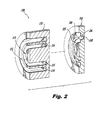
- Nozzle 200 has a nozzle body 202, backing member 210, flow channel 204, swirl antechamber 206, injection point orifice 208, fluid inlet chamber 212, and passages 214 much as described above with respect to Fig. 1 .
- nozzle 200 includes a second annular flow channel 205 inboard of the first flow channel 204.
- Nozzle 200 also includes a second fluid inlet chamber 213 inboard of the first inlet chamber 212.
- Inlet chamber 213 includes passages 215 that can be configured to generate a flow in flow channel 205 that co-swirls or counter-swirls with flow in flow channel 204.
- the direction of flow in the separate passages as they feed into the swirl ante-chamber may be directed either to aid swirl in the swirl ante-chamber 206 or may weaken the amount of swirl, depending on the respective angles of passages 214 and 215.
- Figs. 2-4 only show one swirl ante-chamber 206 and orifice 208 for simplicity, however as will be described below, there are actually four of each.
- the flow directions in the circuitous flow channels 204 and 205 are indicated in the case where passages 214 and 215 described above are angled to create co-swirling flow in swirl ante-chamber 206.
- flow apportionment between the two flow channels 204 and 205 can be used to control the spray angle issuing from orifice 208. For example, if the total flow is apportioned through flow channel 205, with no flow through flow channel 204, a base spray angle will be produced. If flow is apportioned with half of the flow through each channel 204 and 205, then the swirl will increase and the spray angle will be wider than the base spray angle.
- flow directions in flow channels 204 and 205 are indicated in the case where passages 214 and 215 are angled to create counter-swirling flow in swirl ante-chamber 206.
- flow apportionment between the two flow channels 204 and 205 can be used to control the spray angle issuing from orifice 208 as follows. If the total flow is apportioned through flow channel 205, with no flow through flow channel 204, a base spray angle will be produced. If flow is apportioned with half of the flow through each channel 204 and 205, then the swirl will be decreased and the spray angle will be narrower than the base spray angle.
- nozzle 200 can provide the advantage of variable swirl angle ability.
- the directional geometry is set to counter-swirl into the swirl ante-chambers, there is a large degree of controllability on the swirl angle. For example, fixing the total flow rate into the injector (say 100 lb/hr or 45.36 kg/hr), if all of the flow goes through only 1 of the 2 channels, it will give a certain spray angle out of the exit orifice(s), for example 60°.
- variable swirl angle can include the following.
- nozzle 200 with two flow channels 204 and 205 demonstrate variable spray angle.
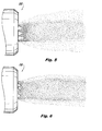
- This geometry has a flow number of roughly 12 with four separate multi-point injection orifices. There is no outlet conic on the injection points, so the images in Figs. 5-6 show the natural cone angles.
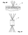
- Fig. 5 shows the degree of controllability - at a constant pressure (100 psi or 689 kPa), the spray angles can be varied from about 55° degrees down to a spray angle of about 25° in Fig. 6.
- Figs. 5 and 6 show the same nozzle 200, both with overall pressure at 100 psi (689 kPa).
- Fig. 5 shows the spray when 100% of the flow is through only one channel.
- Fig. 5 shows the spray when 100% of the flow is through only one channel.
- FIG. 6 shows the spray when the flow is split roughly evenly between the two flow channels 204 and 205.
- nozzle 200 is a multi-point design, the overall injector will not be skewed if individual points are all skewed the same way.
- any suitable fluid can be swirled as described above.
- the principles used to swirl fluids in injectors 100 and 200 can similarly be used for controlling air.
- air is split into two separate inlet chambers, which respectively feed into similarly oriented directional passages. This allows for the air flow angle to be controlled fluidically, very similar to the way the liquid spray angle is controlled in nozzle 200.
- Injector 300 includes inlet chambers 312 and 313 and respective flow passages 314 and 315 which operate as described above.
- the exit orifices 308 are upstream of a prefilming surface 316.
- the spray from orifices 308 is allowed to film along a prefilming surface 316.
- each point of the multipoint injector be an individual air-assist point, which may be referred to as a multi-air-assist point injector.
- this can be accomplished by putting one or more air channels 407 down the center of each swirl ante-chamber 406. Air channels 407 are shown separated from their respective swirl ante-chambers 406 in Fig. 9 .
- the fuel channels add swirl into swirl ante-chambers 406 in a similar way to that described above with respect to nozzle 200.
- the flow swirls in swirl ante-chamber 406 and may then film along a filming surface 409 where it then meets up with the inner air from air channel 407 at orifice 408 and air from outer air channels.
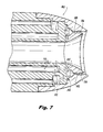
- the outer air channels are not shown in Figs. 8-10 for simplicity, but see, e.g., Figs. 7 and 17 .
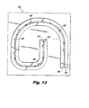
- Figs. 11-13 show examples of the ease of designing the location of the exit points any way that will best fit particular applications. After the exit point locations are determined, the channels may then be located and sized to fit the exit points. Those skilled in the art will readily appreciate that this allows great flexibility in design.
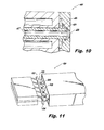
- Fig. 11 shows a negative rendering (flow cavities shown as solid) of a multi-point injector 500 with a linear pattern of injection point orifices 508.
- Flow channels 504 and 505 operate much as those described above with respect to nozzle 200 to control the spray issuing from orifices 508. As shown schematically in Fig. 12 , this linear configuration allows multiple injection point orifices 508 to be oriented and attached on a single feed arm and attached externally around a full annular combustor 10. Two multi-point injectors 500 are shown schematically mounted to combustor 10 in Fig. 12 for simplicity, however, multiple injectors 500 could be mounted to fill the entire circumference around combustor 10. Fig. 13 shows another example of the flexibility of exit point location in accordance with the present invention.
- injector 600 eight injection point orifices 608 are arranged in an arbitrary pattern, and the two flow channels 604 and 605 are routed accordingly.
- the flexibility to have arbitrarily designed fuel passages can help to optimize thermal-management, emissions, operability, and the like.
- Spray angle control as described herein provides the potential for improved advanced active combustion control. Since the spray angle can be controlled fluidically instead of mechanically, a faster response time can be achieved than in other active combustion control devices. This can be realized by changing the spray angles in a controlled method to counteract unwanted thermal-acoustic instabilities, i.e. rumble, without the need to change the overall mass flow rate of the injector, but instead by simply adjusting the flow splits between flow channels. Additionally, due to the fluidic control of exemplary embodiments described herein, it may be possible to find a fluidically controllable instability, which could also be used to control the unwanted thermal-acoustic instabilities.
- additional flow channels may be added to change features of the spray including spray quality, multi-fuel (gas or liquid) ability, and the like. These channels can meet in the directional passages or in the swirl ante-chamber depending on the intent of the design.
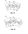
- FIG. 14 shows a schematic of an injector 700 for staging multiple injector points.
- injector 700 the spray angle of alternating injection points can be independently controlled.
- a first set of injection points 708a alternates circumferentially around injector 700 with a second set of injection points 708b.
- One flow channel 704 feeds both sets of injection points 708a and 708b.
- a second flow channel 705a feeds only injection points 708a
- a third flow channel 705b feeds only injection points 708b.
- Changing the apportionment of flow among the three flow channels 704, 705a, and 705b allows separate staging and spray angle control of injection points 708a and 708b.
- Similar channel configurations can be used instead to control individual duplex channels or air-assist atomizer points in addition to simplex injector points. It is also contemplated that providing four flow channels, two each for two separate sets of injection points, allows for completely independent operation and spray angle control for the two sets of injection points.
- injector 800 includes swirl slots 803 that impose a tangential component onto flow coming in from an axial direction, for example, to flow in the clockwise direction (as oriented in Fig. 15 ) around each flow channel 804 and 805.
- injector 800 is exemplary only, and that any other suitable arrangement for imparting flow direction can be used without departing from the scope of the invention.
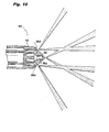
- FIG. 16 another exemplary embodiment of an injector 900 includes axial and non-axially oriented injection point orifices and swirl ante-chambers.
- Nozzle body 902 and backing member 910 supply two-channel fuel supplies to be sprayed, much as described above.
- a single, central swirl ante-chamber 906a is oriented in an axial direction as those described above.
- a plurality of diverging swirl ante-chambers 906b circumferentially surround central swirl ante-chamber 906a. Each of swirl ante-chambers 906b diverges relative the longitudinal axis of central swirl ante-chamber 906a.
- the respective outlet orifices are shown being aligned with their respective swirl ante-chambers, however, swirl ante-chambers 906b are not aligned axially with their underlying flow channels (not labeled in Fig. 16 , but see, e.g., flow channels 204 and 205 in Fig. 2 ). Moreover, it is also possible for a swirl ante-chamber and its orifice to be out of alignment with one another.
- the centerline outlet orifice can be staged separately from the other outlet orifices as described above with reference to Fig. 14 , for example for use as a pilot fuel stage in a gas turbine engine.
- the overall spray pattern with all the injection points operating is shown schematically in Fig. 16 .
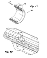
- FIG. 17 schematically shows the cross-flowing air.
- Swirl ante-chamber 1006 and orifice 1008 are shown enlarged in Fig. 18 , where flow channels 1004 and 1005 are shown feeding into swirl ante-chamber 1006.
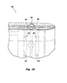
- Flow channels 1004 and 1005 are fed by radial slots 1003, as indicated schematically in Fig. 19 , which operate much like radial swirl slots 803 described above.
- radial spray can be to tailor the penetration of the fuel into the air at different engine conditions.
- the idle condition may be such that the desired mass flow rate of fuel would penetrate completely through the air to the other side and impinge on an outer face of the nozzle (which is undesirable).
- injector 1000 With injector 1000, the spray angle can be adjusted so it has a wider spray at this condition and does not impinge.
- the spray angle can be narrowed down to behave similar to a plain jet which allows for further penetration of the fuel into this dense air.
- Injector 1100 includes a nozzle body 1102 as described above with respect to Fig. 15 , backing member 1110, and intermediate member 1112.
- Intermediate member 1112 includes through chambers 1130 that when assembled as shown in Fig. 23 are aligned with every other swirl ante-chamber 1106.
- a third flow channel 1132 is defined in intermediate member 1112 for supplying boost flow to the one half of the swirl ante-chambers 1106 having through chambers 1130, which boost flow is in addition to the flow from the two flow channels defined in nozzle body 1102. Figs.
- 22 and 23 are schematic in that the full flow circuitry, e.g., inlets, of backing and intermediate members 1110 and 1112 is not shown for sake of simplicity.
- This configuration allows control to boost the amount of fuel into half of the injectors, as when staging fuel, while still maintaining the ability to control the spray angles.
- This configuration also allows for a controllable-angle duplex atomizer as well as multi-fuel applications.
- FIG. 24 another exemplary embodiment of an injector 1200 includes four flow channels where two flow channels 1204 and 1205 are defined in nozzle body 1202, and two flow channels 1232 and 1234 are defined in intermediate member 1212.
- This configuration allows for staging and/or multi-fuel capability, wherein flows in flow channels 1204 and 1205 can be boosted by flows from flow channels 1232 and 1234, respectively.
- Figs. 24 and 25 can be compared to Figs. 22 and 23 described above, and are similarly schematic for sake of clarity.
Landscapes
- Engineering & Computer Science (AREA)
- Chemical & Material Sciences (AREA)
- Combustion & Propulsion (AREA)
- Mechanical Engineering (AREA)
- General Engineering & Computer Science (AREA)
- Nozzles (AREA)
Applications Claiming Priority (1)
| Application Number | Priority Date | Filing Date | Title |
|---|---|---|---|
| US201261599659P | 2012-02-16 | 2012-02-16 |
Publications (3)
| Publication Number | Publication Date |
|---|---|
| EP2629016A2 true EP2629016A2 (de) | 2013-08-21 |
| EP2629016A3 EP2629016A3 (de) | 2017-05-17 |
| EP2629016B1 EP2629016B1 (de) | 2019-09-18 |
Family
ID=47722114
Family Applications (1)
| Application Number | Title | Priority Date | Filing Date |
|---|---|---|---|
| EP13155488.3A Active EP2629016B1 (de) | 2012-02-16 | 2013-02-15 | Mehrpunkteinspritzung mit verstellbarem Winkel |
Country Status (2)
| Country | Link |
|---|---|
| US (2) | US9745936B2 (de) |
| EP (1) | EP2629016B1 (de) |
Cited By (4)
| Publication number | Priority date | Publication date | Assignee | Title |
|---|---|---|---|---|
| CN105927980A (zh) * | 2016-06-13 | 2016-09-07 | 南京航空航天大学 | 一种用于贫油直喷燃烧室的燃料多点均匀喷射系统 |
| EP3196554A1 (de) * | 2016-01-21 | 2017-07-26 | Delavan, Inc. | Diskrete strahlenöffnungen |
| EP3348813A1 (de) * | 2017-01-17 | 2018-07-18 | Delavan, Inc. | Interne kraftstoffverteiler und herstellungsverfahren |
| CN111859749A (zh) * | 2020-07-15 | 2020-10-30 | 西安交通大学 | 一种基于n-s方程的射流喷射角的确定方法 |
Families Citing this family (23)
| Publication number | Priority date | Publication date | Assignee | Title |
|---|---|---|---|---|
| DE102012201178B3 (de) * | 2012-01-27 | 2013-02-14 | Aptar Radolfzell Gmbh | Düseneinheit und Spender mit einer solchen |
| US9745936B2 (en) * | 2012-02-16 | 2017-08-29 | Delavan Inc | Variable angle multi-point injection |
| FR3001497B1 (fr) * | 2013-01-29 | 2016-05-13 | Turbomeca | Ensemble de combustion de turbomachine comprenant un circuit d alimentation de carburant ameliore |
| DE102015205837B4 (de) | 2014-05-21 | 2017-02-16 | Ford Global Technologies, Llc | Kraftfahrzeug und Betriebsverfahren |
| US9765972B2 (en) | 2015-01-30 | 2017-09-19 | Delavan Inc. | Fuel injectors for gas turbine engines |
| US20160237879A1 (en) * | 2015-02-16 | 2016-08-18 | Caterpillar Inc. | Fuel Combustion System Having Component with Thermal Conductor Member and Method of Making Same |
| KR101657535B1 (ko) * | 2015-05-21 | 2016-09-19 | 두산중공업 주식회사 | 버닝 저감 연료공급노즐. |
| US20170108222A1 (en) * | 2015-10-16 | 2017-04-20 | Delavan Inc | Variable angle spray cone injection |
| US10859269B2 (en) | 2017-03-31 | 2020-12-08 | Delavan Inc. | Fuel injectors for multipoint arrays |
| US10941941B2 (en) * | 2018-07-05 | 2021-03-09 | Solar Turbines Incorporated | Fuel injector with a center body assembly |
| KR102929685B1 (ko) | 2019-02-20 | 2026-02-23 | 삼성전자주식회사 | 전자 장치 및 그 제어 방법 |
| US11454395B2 (en) | 2020-04-24 | 2022-09-27 | Collins Engine Nozzles, Inc. | Thermal resistant air caps |
| US11938907B2 (en) | 2020-10-29 | 2024-03-26 | Oliver Crispin Robotics Limited | Systems and methods of servicing equipment |
| US12208925B2 (en) | 2020-10-29 | 2025-01-28 | General Electric Company | Systems and methods of servicing equipment |
| US12139109B2 (en) | 2020-10-29 | 2024-11-12 | General Electric Company | Systems and methods of servicing equipment |
| US11685051B2 (en) | 2020-10-29 | 2023-06-27 | General Electric Company | Systems and methods of servicing equipment |
| US11935290B2 (en) | 2020-10-29 | 2024-03-19 | Oliver Crispin Robotics Limited | Systems and methods of servicing equipment |
| US11874653B2 (en) | 2020-10-29 | 2024-01-16 | Oliver Crispin Robotics Limited | Systems and methods of servicing equipment |
| US11992952B2 (en) | 2020-10-29 | 2024-05-28 | General Electric Company | Systems and methods of servicing equipment |
| US12511623B2 (en) | 2020-10-29 | 2025-12-30 | General Electric Company | Systems and methods of servicing equipment |
| US11915531B2 (en) | 2020-10-29 | 2024-02-27 | General Electric Company | Systems and methods of servicing equipment |
| US11384937B1 (en) | 2021-05-12 | 2022-07-12 | General Electric Company | Swirler with integrated damper |
| KR102720524B1 (ko) * | 2022-06-30 | 2024-10-23 | 두산에너빌리티 주식회사 | 제트 노즐, 연소기 및 이를 포함하는 가스터빈 |
Citations (2)
| Publication number | Priority date | Publication date | Assignee | Title |
|---|---|---|---|---|
| US20110031333A1 (en) | 2009-08-04 | 2011-02-10 | Delavan Inc | Multi-point injector ring |
| US20120292408A1 (en) | 2011-05-18 | 2012-11-22 | Delavan Inc. | Multipoint injectors with standard envelope characteristics |
Family Cites Families (34)
| Publication number | Priority date | Publication date | Assignee | Title |
|---|---|---|---|---|
| US2607193A (en) | 1947-10-25 | 1952-08-19 | Curtiss Wright Corp | Annular combustion chamber with multiple notched fuel nozzles |
| US2628867A (en) | 1948-01-07 | 1953-02-17 | Gen Motors Corp | Duplex nozzle |
| US3680793A (en) | 1970-11-09 | 1972-08-01 | Delavan Manufacturing Co | Eccentric spiral swirl chamber nozzle |
| JPS57187531A (en) | 1981-05-12 | 1982-11-18 | Hitachi Ltd | Low nox gas turbine burner |
| DE3312301A1 (de) | 1983-04-06 | 1984-10-11 | Basf Ag, 6700 Ludwigshafen | Hohlkegelzerstaeubungsduese |
| US5409169A (en) | 1991-06-19 | 1995-04-25 | Hitachi America, Ltd. | Air-assist fuel injection system |
| US5361586A (en) | 1993-04-15 | 1994-11-08 | Westinghouse Electric Corporation | Gas turbine ultra low NOx combustor |
| DE19608349A1 (de) | 1996-03-05 | 1997-09-11 | Abb Research Ltd | Druckzerstäuberdüse |
| GB2319078B (en) | 1996-11-08 | 1999-11-03 | Europ Gas Turbines Ltd | Combustor arrangement |
| US6092363A (en) | 1998-06-19 | 2000-07-25 | Siemens Westinghouse Power Corporation | Low Nox combustor having dual fuel injection system |
| CA2335349C (en) | 1998-06-26 | 2008-10-07 | Lev A. Prociw | Fuel injector for gas turbine engine |
| US6547163B1 (en) * | 1999-10-01 | 2003-04-15 | Parker-Hannifin Corporation | Hybrid atomizing fuel nozzle |
| US6533954B2 (en) | 2000-02-28 | 2003-03-18 | Parker-Hannifin Corporation | Integrated fluid injection air mixing system |
| US6363726B1 (en) | 2000-09-29 | 2002-04-02 | General Electric Company | Mixer having multiple swirlers |
| US6688534B2 (en) | 2001-03-07 | 2004-02-10 | Delavan Inc | Air assist fuel nozzle |
| US6622488B2 (en) | 2001-03-21 | 2003-09-23 | Parker-Hannifin Corporation | Pure airblast nozzle |
| US6755024B1 (en) | 2001-08-23 | 2004-06-29 | Delavan Inc. | Multiplex injector |
| DE10211590B4 (de) | 2002-03-15 | 2007-11-08 | J. Eberspächer GmbH & Co. KG | Zerstäuberdüse, insbesondere für ein Fahrzeugheizgerät |
| US6854670B2 (en) | 2002-05-17 | 2005-02-15 | Keihin Corporation | Fuel injection valve |
| US6962055B2 (en) | 2002-09-27 | 2005-11-08 | United Technologies Corporation | Multi-point staging strategy for low emission and stable combustion |
| US6863228B2 (en) | 2002-09-30 | 2005-03-08 | Delavan Inc. | Discrete jet atomizer |
| US7174717B2 (en) | 2003-12-24 | 2007-02-13 | Pratt & Whitney Canada Corp. | Helical channel fuel distributor and method |
| US7533531B2 (en) | 2005-04-01 | 2009-05-19 | Pratt & Whitney Canada Corp. | Internal fuel manifold with airblast nozzles |
| JP2007155170A (ja) | 2005-12-02 | 2007-06-21 | Hitachi Ltd | 燃料ノズル,ガスタービン燃焼器,ガスタービン燃焼器の燃料ノズル及びガスタービン燃焼器の改造方法 |
| US7520134B2 (en) | 2006-09-29 | 2009-04-21 | General Electric Company | Methods and apparatus for injecting fluids into a turbine engine |
| JP2010519963A (ja) * | 2007-02-28 | 2010-06-10 | アボツト・レスピラトリー・エル・エル・シー | ノズル形式の噴霧システム |
| US7926178B2 (en) | 2007-11-30 | 2011-04-19 | Delavan Inc | Method of fuel nozzle construction |
| US7926744B2 (en) * | 2008-02-21 | 2011-04-19 | Delavan Inc | Radially outward flowing air-blast fuel injector for gas turbine engine |
| US7926282B2 (en) | 2008-03-04 | 2011-04-19 | Delavan Inc | Pure air blast fuel injector |
| US20090255258A1 (en) | 2008-04-11 | 2009-10-15 | Delavan Inc | Pre-filming air-blast fuel injector having a reduced hydraulic spray angle |
| US8234873B2 (en) | 2008-08-28 | 2012-08-07 | Woodward, Inc. | Multi passage fuel manifold and methods of construction |
| US8851401B2 (en) * | 2011-03-18 | 2014-10-07 | Delavan Inc. | Flat fan air assist injectors |
| US9745936B2 (en) * | 2012-02-16 | 2017-08-29 | Delavan Inc | Variable angle multi-point injection |
| US9400104B2 (en) * | 2012-09-28 | 2016-07-26 | United Technologies Corporation | Flow modifier for combustor fuel nozzle tip |
-
2013
- 2013-02-14 US US13/767,402 patent/US9745936B2/en active Active
- 2013-02-15 EP EP13155488.3A patent/EP2629016B1/de active Active
-
2017
- 2017-08-15 US US15/677,617 patent/US10480472B2/en active Active
Patent Citations (2)
| Publication number | Priority date | Publication date | Assignee | Title |
|---|---|---|---|---|
| US20110031333A1 (en) | 2009-08-04 | 2011-02-10 | Delavan Inc | Multi-point injector ring |
| US20120292408A1 (en) | 2011-05-18 | 2012-11-22 | Delavan Inc. | Multipoint injectors with standard envelope characteristics |
Cited By (6)
| Publication number | Priority date | Publication date | Assignee | Title |
|---|---|---|---|---|
| EP3196554A1 (de) * | 2016-01-21 | 2017-07-26 | Delavan, Inc. | Diskrete strahlenöffnungen |
| CN105927980A (zh) * | 2016-06-13 | 2016-09-07 | 南京航空航天大学 | 一种用于贫油直喷燃烧室的燃料多点均匀喷射系统 |
| EP3348813A1 (de) * | 2017-01-17 | 2018-07-18 | Delavan, Inc. | Interne kraftstoffverteiler und herstellungsverfahren |
| US10774748B2 (en) | 2017-01-17 | 2020-09-15 | Delavan Inc. | Internal fuel manifolds |
| CN111859749A (zh) * | 2020-07-15 | 2020-10-30 | 西安交通大学 | 一种基于n-s方程的射流喷射角的确定方法 |
| CN111859749B (zh) * | 2020-07-15 | 2023-05-26 | 西安交通大学 | 一种基于n-s方程的射流喷射角的确定方法 |
Also Published As
| Publication number | Publication date |
|---|---|
| US10480472B2 (en) | 2019-11-19 |
| EP2629016A3 (de) | 2017-05-17 |
| US9745936B2 (en) | 2017-08-29 |
| EP2629016B1 (de) | 2019-09-18 |
| US20130214063A1 (en) | 2013-08-22 |
| US20180010563A1 (en) | 2018-01-11 |
Similar Documents
| Publication | Publication Date | Title |
|---|---|---|
| US10480472B2 (en) | Variable angle multi-point injection | |
| US12055295B2 (en) | Fuel nozzle structure for air assist injection | |
| EP2525152B1 (de) | Mehrpunkt-Einspritzungsring | |
| US8313046B2 (en) | Multi-point injector ring | |
| US9482433B2 (en) | Multi-swirler fuel/air mixer with centralized fuel injection | |
| US6655145B2 (en) | Fuel nozzle for a gas turbine engine | |
| US6533954B2 (en) | Integrated fluid injection air mixing system | |
| EP3336433B1 (de) | Gestufte doppelbrennstoffradialdüse mit radialem flüssigbrennstoffverteiler | |
| US10883719B2 (en) | Prefilming fuel/air mixer | |
| US9333518B2 (en) | Multipoint injectors | |
| KR19980018381A (ko) | 가스 터빈 연소기용 연료 노즐 조립체 및 액체 연료 분사 방법 | |
| US8851401B2 (en) | Flat fan air assist injectors | |
| WO2017120039A1 (en) | Fuel injector with dual main fuel injection | |
| US6550696B2 (en) | Integrated fuel injection and mixing system with impingement cooling face | |
| US10082082B2 (en) | Fuel injector with multi tube gas distribution | |
| CA3175965A1 (en) | Fuel nozzle with restricted core air passage | |
| EP3465009B1 (de) | Brennstoffdüse für eine gasturbine mit radialem drallerzeuger und axialem drallerzeuger und gasturbine | |
| US20170108222A1 (en) | Variable angle spray cone injection | |
| US11448175B1 (en) | Fuel nozzle |
Legal Events
| Date | Code | Title | Description |
|---|---|---|---|
| PUAI | Public reference made under article 153(3) epc to a published international application that has entered the european phase |
Free format text: ORIGINAL CODE: 0009012 |
|
| AK | Designated contracting states |
Kind code of ref document: A2 Designated state(s): AL AT BE BG CH CY CZ DE DK EE ES FI FR GB GR HR HU IE IS IT LI LT LU LV MC MK MT NL NO PL PT RO RS SE SI SK SM TR |
|
| AX | Request for extension of the european patent |
Extension state: BA ME |
|
| PUAL | Search report despatched |
Free format text: ORIGINAL CODE: 0009013 |
|
| AK | Designated contracting states |
Kind code of ref document: A3 Designated state(s): AL AT BE BG CH CY CZ DE DK EE ES FI FR GB GR HR HU IE IS IT LI LT LU LV MC MK MT NL NO PL PT RO RS SE SI SK SM TR |
|
| AX | Request for extension of the european patent |
Extension state: BA ME |
|
| RIC1 | Information provided on ipc code assigned before grant |
Ipc: F23R 3/28 20060101AFI20170410BHEP Ipc: F02C 7/22 20060101ALI20170410BHEP Ipc: F23D 11/38 20060101ALI20170410BHEP |
|
| STAA | Information on the status of an ep patent application or granted ep patent |
Free format text: STATUS: REQUEST FOR EXAMINATION WAS MADE |
|
| 17P | Request for examination filed |
Effective date: 20171114 |
|
| RBV | Designated contracting states (corrected) |
Designated state(s): AL AT BE BG CH CY CZ DE DK EE ES FI FR GB GR HR HU IE IS IT LI LT LU LV MC MK MT NL NO PL PT RO RS SE SI SK SM TR |
|
| GRAP | Despatch of communication of intention to grant a patent |
Free format text: ORIGINAL CODE: EPIDOSNIGR1 |
|
| STAA | Information on the status of an ep patent application or granted ep patent |
Free format text: STATUS: GRANT OF PATENT IS INTENDED |
|
| RIC1 | Information provided on ipc code assigned before grant |
Ipc: F23D 11/38 20060101ALI20190311BHEP Ipc: F23R 3/28 20060101AFI20190311BHEP Ipc: F02C 7/22 20060101ALI20190311BHEP |
|
| INTG | Intention to grant announced |
Effective date: 20190327 |
|
| GRAS | Grant fee paid |
Free format text: ORIGINAL CODE: EPIDOSNIGR3 |
|
| GRAA | (expected) grant |
Free format text: ORIGINAL CODE: 0009210 |
|
| STAA | Information on the status of an ep patent application or granted ep patent |
Free format text: STATUS: THE PATENT HAS BEEN GRANTED |
|
| AK | Designated contracting states |
Kind code of ref document: B1 Designated state(s): AL AT BE BG CH CY CZ DE DK EE ES FI FR GB GR HR HU IE IS IT LI LT LU LV MC MK MT NL NO PL PT RO RS SE SI SK SM TR |
|
| REG | Reference to a national code |
Ref country code: GB Ref legal event code: FG4D |
|
| REG | Reference to a national code |
Ref country code: CH Ref legal event code: EP |
|
| REG | Reference to a national code |
Ref country code: DE Ref legal event code: R096 Ref document number: 602013060586 Country of ref document: DE |
|
| REG | Reference to a national code |
Ref country code: AT Ref legal event code: REF Ref document number: 1181782 Country of ref document: AT Kind code of ref document: T Effective date: 20191015 |
|
| REG | Reference to a national code |
Ref country code: IE Ref legal event code: FG4D |
|
| REG | Reference to a national code |
Ref country code: NL Ref legal event code: MP Effective date: 20190918 |
|
| PG25 | Lapsed in a contracting state [announced via postgrant information from national office to epo] |
Ref country code: HR Free format text: LAPSE BECAUSE OF FAILURE TO SUBMIT A TRANSLATION OF THE DESCRIPTION OR TO PAY THE FEE WITHIN THE PRESCRIBED TIME-LIMIT Effective date: 20190918 Ref country code: SE Free format text: LAPSE BECAUSE OF FAILURE TO SUBMIT A TRANSLATION OF THE DESCRIPTION OR TO PAY THE FEE WITHIN THE PRESCRIBED TIME-LIMIT Effective date: 20190918 Ref country code: FI Free format text: LAPSE BECAUSE OF FAILURE TO SUBMIT A TRANSLATION OF THE DESCRIPTION OR TO PAY THE FEE WITHIN THE PRESCRIBED TIME-LIMIT Effective date: 20190918 Ref country code: NO Free format text: LAPSE BECAUSE OF FAILURE TO SUBMIT A TRANSLATION OF THE DESCRIPTION OR TO PAY THE FEE WITHIN THE PRESCRIBED TIME-LIMIT Effective date: 20191218 Ref country code: BG Free format text: LAPSE BECAUSE OF FAILURE TO SUBMIT A TRANSLATION OF THE DESCRIPTION OR TO PAY THE FEE WITHIN THE PRESCRIBED TIME-LIMIT Effective date: 20191218 Ref country code: LT Free format text: LAPSE BECAUSE OF FAILURE TO SUBMIT A TRANSLATION OF THE DESCRIPTION OR TO PAY THE FEE WITHIN THE PRESCRIBED TIME-LIMIT Effective date: 20190918 |
|
| REG | Reference to a national code |
Ref country code: LT Ref legal event code: MG4D |
|
| PG25 | Lapsed in a contracting state [announced via postgrant information from national office to epo] |
Ref country code: RS Free format text: LAPSE BECAUSE OF FAILURE TO SUBMIT A TRANSLATION OF THE DESCRIPTION OR TO PAY THE FEE WITHIN THE PRESCRIBED TIME-LIMIT Effective date: 20190918 Ref country code: LV Free format text: LAPSE BECAUSE OF FAILURE TO SUBMIT A TRANSLATION OF THE DESCRIPTION OR TO PAY THE FEE WITHIN THE PRESCRIBED TIME-LIMIT Effective date: 20190918 Ref country code: GR Free format text: LAPSE BECAUSE OF FAILURE TO SUBMIT A TRANSLATION OF THE DESCRIPTION OR TO PAY THE FEE WITHIN THE PRESCRIBED TIME-LIMIT Effective date: 20191219 Ref country code: AL Free format text: LAPSE BECAUSE OF FAILURE TO SUBMIT A TRANSLATION OF THE DESCRIPTION OR TO PAY THE FEE WITHIN THE PRESCRIBED TIME-LIMIT Effective date: 20190918 |
|
| REG | Reference to a national code |
Ref country code: AT Ref legal event code: MK05 Ref document number: 1181782 Country of ref document: AT Kind code of ref document: T Effective date: 20190918 |
|
| PG25 | Lapsed in a contracting state [announced via postgrant information from national office to epo] |
Ref country code: PT Free format text: LAPSE BECAUSE OF FAILURE TO SUBMIT A TRANSLATION OF THE DESCRIPTION OR TO PAY THE FEE WITHIN THE PRESCRIBED TIME-LIMIT Effective date: 20200120 Ref country code: NL Free format text: LAPSE BECAUSE OF FAILURE TO SUBMIT A TRANSLATION OF THE DESCRIPTION OR TO PAY THE FEE WITHIN THE PRESCRIBED TIME-LIMIT Effective date: 20190918 Ref country code: PL Free format text: LAPSE BECAUSE OF FAILURE TO SUBMIT A TRANSLATION OF THE DESCRIPTION OR TO PAY THE FEE WITHIN THE PRESCRIBED TIME-LIMIT Effective date: 20190918 Ref country code: ES Free format text: LAPSE BECAUSE OF FAILURE TO SUBMIT A TRANSLATION OF THE DESCRIPTION OR TO PAY THE FEE WITHIN THE PRESCRIBED TIME-LIMIT Effective date: 20190918 Ref country code: RO Free format text: LAPSE BECAUSE OF FAILURE TO SUBMIT A TRANSLATION OF THE DESCRIPTION OR TO PAY THE FEE WITHIN THE PRESCRIBED TIME-LIMIT Effective date: 20190918 Ref country code: IT Free format text: LAPSE BECAUSE OF FAILURE TO SUBMIT A TRANSLATION OF THE DESCRIPTION OR TO PAY THE FEE WITHIN THE PRESCRIBED TIME-LIMIT Effective date: 20190918 Ref country code: EE Free format text: LAPSE BECAUSE OF FAILURE TO SUBMIT A TRANSLATION OF THE DESCRIPTION OR TO PAY THE FEE WITHIN THE PRESCRIBED TIME-LIMIT Effective date: 20190918 Ref country code: AT Free format text: LAPSE BECAUSE OF FAILURE TO SUBMIT A TRANSLATION OF THE DESCRIPTION OR TO PAY THE FEE WITHIN THE PRESCRIBED TIME-LIMIT Effective date: 20190918 |
|
| PG25 | Lapsed in a contracting state [announced via postgrant information from national office to epo] |
Ref country code: SM Free format text: LAPSE BECAUSE OF FAILURE TO SUBMIT A TRANSLATION OF THE DESCRIPTION OR TO PAY THE FEE WITHIN THE PRESCRIBED TIME-LIMIT Effective date: 20190918 Ref country code: CZ Free format text: LAPSE BECAUSE OF FAILURE TO SUBMIT A TRANSLATION OF THE DESCRIPTION OR TO PAY THE FEE WITHIN THE PRESCRIBED TIME-LIMIT Effective date: 20190918 Ref country code: IS Free format text: LAPSE BECAUSE OF FAILURE TO SUBMIT A TRANSLATION OF THE DESCRIPTION OR TO PAY THE FEE WITHIN THE PRESCRIBED TIME-LIMIT Effective date: 20200224 Ref country code: SK Free format text: LAPSE BECAUSE OF FAILURE TO SUBMIT A TRANSLATION OF THE DESCRIPTION OR TO PAY THE FEE WITHIN THE PRESCRIBED TIME-LIMIT Effective date: 20190918 |
|
| REG | Reference to a national code |
Ref country code: DE Ref legal event code: R097 Ref document number: 602013060586 Country of ref document: DE |
|
| PLBE | No opposition filed within time limit |
Free format text: ORIGINAL CODE: 0009261 |
|
| STAA | Information on the status of an ep patent application or granted ep patent |
Free format text: STATUS: NO OPPOSITION FILED WITHIN TIME LIMIT |
|
| PG2D | Information on lapse in contracting state deleted |
Ref country code: IS |
|
| PG25 | Lapsed in a contracting state [announced via postgrant information from national office to epo] |
Ref country code: DK Free format text: LAPSE BECAUSE OF FAILURE TO SUBMIT A TRANSLATION OF THE DESCRIPTION OR TO PAY THE FEE WITHIN THE PRESCRIBED TIME-LIMIT Effective date: 20190918 Ref country code: IS Free format text: LAPSE BECAUSE OF FAILURE TO SUBMIT A TRANSLATION OF THE DESCRIPTION OR TO PAY THE FEE WITHIN THE PRESCRIBED TIME-LIMIT Effective date: 20200119 |
|
| 26N | No opposition filed |
Effective date: 20200619 |
|
| PG25 | Lapsed in a contracting state [announced via postgrant information from national office to epo] |
Ref country code: SI Free format text: LAPSE BECAUSE OF FAILURE TO SUBMIT A TRANSLATION OF THE DESCRIPTION OR TO PAY THE FEE WITHIN THE PRESCRIBED TIME-LIMIT Effective date: 20190918 |
|
| REG | Reference to a national code |
Ref country code: CH Ref legal event code: PL |
|
| REG | Reference to a national code |
Ref country code: BE Ref legal event code: MM Effective date: 20200229 |
|
| PG25 | Lapsed in a contracting state [announced via postgrant information from national office to epo] |
Ref country code: LU Free format text: LAPSE BECAUSE OF NON-PAYMENT OF DUE FEES Effective date: 20200215 Ref country code: MC Free format text: LAPSE BECAUSE OF FAILURE TO SUBMIT A TRANSLATION OF THE DESCRIPTION OR TO PAY THE FEE WITHIN THE PRESCRIBED TIME-LIMIT Effective date: 20190918 |
|
| PG25 | Lapsed in a contracting state [announced via postgrant information from national office to epo] |
Ref country code: LI Free format text: LAPSE BECAUSE OF NON-PAYMENT OF DUE FEES Effective date: 20200229 Ref country code: CH Free format text: LAPSE BECAUSE OF NON-PAYMENT OF DUE FEES Effective date: 20200229 |
|
| PG25 | Lapsed in a contracting state [announced via postgrant information from national office to epo] |
Ref country code: IE Free format text: LAPSE BECAUSE OF NON-PAYMENT OF DUE FEES Effective date: 20200215 |
|
| PG25 | Lapsed in a contracting state [announced via postgrant information from national office to epo] |
Ref country code: BE Free format text: LAPSE BECAUSE OF NON-PAYMENT OF DUE FEES Effective date: 20200229 |
|
| PG25 | Lapsed in a contracting state [announced via postgrant information from national office to epo] |
Ref country code: TR Free format text: LAPSE BECAUSE OF FAILURE TO SUBMIT A TRANSLATION OF THE DESCRIPTION OR TO PAY THE FEE WITHIN THE PRESCRIBED TIME-LIMIT Effective date: 20190918 Ref country code: MT Free format text: LAPSE BECAUSE OF FAILURE TO SUBMIT A TRANSLATION OF THE DESCRIPTION OR TO PAY THE FEE WITHIN THE PRESCRIBED TIME-LIMIT Effective date: 20190918 Ref country code: CY Free format text: LAPSE BECAUSE OF FAILURE TO SUBMIT A TRANSLATION OF THE DESCRIPTION OR TO PAY THE FEE WITHIN THE PRESCRIBED TIME-LIMIT Effective date: 20190918 |
|
| PG25 | Lapsed in a contracting state [announced via postgrant information from national office to epo] |
Ref country code: MK Free format text: LAPSE BECAUSE OF FAILURE TO SUBMIT A TRANSLATION OF THE DESCRIPTION OR TO PAY THE FEE WITHIN THE PRESCRIBED TIME-LIMIT Effective date: 20190918 |
|
| P01 | Opt-out of the competence of the unified patent court (upc) registered |
Effective date: 20230530 |
|
| PGFP | Annual fee paid to national office [announced via postgrant information from national office to epo] |
Ref country code: GB Payment date: 20260122 Year of fee payment: 14 |
|
| PGFP | Annual fee paid to national office [announced via postgrant information from national office to epo] |
Ref country code: DE Payment date: 20260121 Year of fee payment: 14 |
|
| PGFP | Annual fee paid to national office [announced via postgrant information from national office to epo] |
Ref country code: FR Payment date: 20260121 Year of fee payment: 14 |