EP3196554A1 - Diskrete strahlenöffnungen - Google Patents
Diskrete strahlenöffnungen Download PDFInfo
- Publication number
- EP3196554A1 EP3196554A1 EP17151800.4A EP17151800A EP3196554A1 EP 3196554 A1 EP3196554 A1 EP 3196554A1 EP 17151800 A EP17151800 A EP 17151800A EP 3196554 A1 EP3196554 A1 EP 3196554A1
- Authority
- EP
- European Patent Office
- Prior art keywords
- outlet
- nozzle tip
- orifice
- upstream
- tapered inlet
- Prior art date
- Legal status (The legal status is an assumption and is not a legal conclusion. Google has not performed a legal analysis and makes no representation as to the accuracy of the status listed.)
- Withdrawn
Links
Images




Classifications
-
- F—MECHANICAL ENGINEERING; LIGHTING; HEATING; WEAPONS; BLASTING
- F23—COMBUSTION APPARATUS; COMBUSTION PROCESSES
- F23R—GENERATING COMBUSTION PRODUCTS OF HIGH PRESSURE OR HIGH VELOCITY, e.g. GAS-TURBINE COMBUSTION CHAMBERS
- F23R3/00—Continuous combustion chambers using liquid or gaseous fuel
- F23R3/28—Continuous combustion chambers using liquid or gaseous fuel characterised by the fuel supply
-
- F—MECHANICAL ENGINEERING; LIGHTING; HEATING; WEAPONS; BLASTING
- F02—COMBUSTION ENGINES; HOT-GAS OR COMBUSTION-PRODUCT ENGINE PLANTS
- F02C—GAS-TURBINE PLANTS; AIR INTAKES FOR JET-PROPULSION PLANTS; CONTROLLING FUEL SUPPLY IN AIR-BREATHING JET-PROPULSION PLANTS
- F02C7/00—Features, components parts, details or accessories, not provided for in, or of interest apart form groups F02C1/00 - F02C6/00; Air intakes for jet-propulsion plants
- F02C7/22—Fuel supply systems
-
- B—PERFORMING OPERATIONS; TRANSPORTING
- B05—SPRAYING OR ATOMISING IN GENERAL; APPLYING FLUENT MATERIALS TO SURFACES, IN GENERAL
- B05B—SPRAYING APPARATUS; ATOMISING APPARATUS; NOZZLES
- B05B1/00—Nozzles, spray heads or other outlets, with or without auxiliary devices such as valves, heating means
- B05B1/02—Nozzles, spray heads or other outlets, with or without auxiliary devices such as valves, heating means designed to produce a jet, spray, or other discharge of particular shape or nature, e.g. in single drops, or having an outlet of particular shape
-
- B—PERFORMING OPERATIONS; TRANSPORTING
- B05—SPRAYING OR ATOMISING IN GENERAL; APPLYING FLUENT MATERIALS TO SURFACES, IN GENERAL
- B05B—SPRAYING APPARATUS; ATOMISING APPARATUS; NOZZLES
- B05B1/00—Nozzles, spray heads or other outlets, with or without auxiliary devices such as valves, heating means
- B05B1/14—Nozzles, spray heads or other outlets, with or without auxiliary devices such as valves, heating means with multiple outlet openings; with strainers in or outside the outlet opening
-
- F—MECHANICAL ENGINEERING; LIGHTING; HEATING; WEAPONS; BLASTING
- F23—COMBUSTION APPARATUS; COMBUSTION PROCESSES
- F23D—BURNERS
- F23D11/00—Burners using a direct spraying action of liquid droplets or vaporised liquid into the combustion space
- F23D11/36—Details
- F23D11/38—Nozzles; Cleaning devices therefor
-
- F—MECHANICAL ENGINEERING; LIGHTING; HEATING; WEAPONS; BLASTING
- F05—INDEXING SCHEMES RELATING TO ENGINES OR PUMPS IN VARIOUS SUBCLASSES OF CLASSES F01-F04
- F05D—INDEXING SCHEME FOR ASPECTS RELATING TO NON-POSITIVE-DISPLACEMENT MACHINES OR ENGINES, GAS-TURBINES OR JET-PROPULSION PLANTS
- F05D2220/00—Application
- F05D2220/30—Application in turbines
- F05D2220/32—Application in turbines in gas turbines
-
- F—MECHANICAL ENGINEERING; LIGHTING; HEATING; WEAPONS; BLASTING
- F05—INDEXING SCHEMES RELATING TO ENGINES OR PUMPS IN VARIOUS SUBCLASSES OF CLASSES F01-F04
- F05D—INDEXING SCHEME FOR ASPECTS RELATING TO NON-POSITIVE-DISPLACEMENT MACHINES OR ENGINES, GAS-TURBINES OR JET-PROPULSION PLANTS
- F05D2260/00—Function
- F05D2260/60—Fluid transfer
Definitions
- the present disclosure relates to orifices for injectors, spray nozzles, and the like, and more particularly to discrete jet orifices such as used in fuel injectors for gas turbine engines.
- a cylindrical bore is often used as a metering orifice for liquid or gas, such as in fuel injectors, spray nozzles, and the like.
- U.S. Patent No. 7,251,940 describes a fuel nozzle having a fuel shroud that defines a plurality of main fuel jets disposed offset from a central axis. Each of the main fuel jets is a cylindrical bore, which can issue a discrete jet of fuel for combustion in a gas turbine engine.
- a nozzle tip includes a nozzle tip body defining an upstream surface and an opposed downstream surface.
- An outlet orifice is defined through the nozzle tip body for fluid communication from a space upstream of the upstream surface to a space downstream of the downstream surface.
- the outlet orifice includes a cylindrical outlet portion defining an outlet axis, and a tapered inlet portion upstream of the outlet portion. The tapered inlet portion converges down towards the outlet axis in a direction from the upstream surface toward the downstream surface.
- the outlet orifice can be a first outlet orifice, wherein the nozzle tip body includes at least one additional outlet orifice similar to the first outlet orifice.
- the outlet axes of the outlet orifices can diverge away from a central longitudinal axis defined by the nozzle tip body to issue a diverging spray pattern.
- the tapered inlet can converge down toward the outlet axis at an angle less than or equal to 30° and greater than or equal to 10°.
- the tapered inlet portion can extend over half way along the length of the outlet orifice between the upstream surface and the downstream surface. It is also contemplated that the tapered inlet portion can extend over three-quarters of the way along the length of the outlet orifice between the upstream surface and the downstream surface.
- the tapered inlet portion can meet the upstream surface at an orifice inlet edge with a circumference.
- the orifice inlet edge can define an obtuse angle between the tapered inlet portion and the upstream surface around the full circumference of the orifice inlet edge.
- the tapered inlet portion can extend from the orifice inlet edge to the cylindrical outlet portion.
- a nozzle includes a nozzle body defining a feed passage.
- the nozzle also includes a nozzle tip as in any of the embodiments described herein.
- the upstream surface of the nozzle tip is in fluid communication with the feed passage of the nozzle body for supplying a flow of fluid to the outlet orifice.
- the feed passage can include a flow passage that feeds into the outlet orifices that is annular or helical.
- a heat shield can be disposed downstream of the downstream surface of the nozzle tip, wherein an aperture is defined through the heat shield aligned with the outlet orifice to permit issue of fluid from the orifice therethrough.
- a method of forming a nozzle tip includes forming a nozzle tip body with opposed upstream and downstream surfaces.
- the method includes forming a plurality of outlet orifices through the nozzle tip body on respective orifice axes that are angled diverge away from a central longitudinal axis in a downstream direction, each outlet orifice including a cylindrical outlet portion and a tapered inlet portion upstream of the cylindrical outlet portion.
- Forming each outlet orifice can include forming the tapered inlet portion with an EDM tool extending through the cylindrical outlet portion.
- each outlet orifice can include forming the tapered inlet portion in a downstream portion of the nozzle tip body with a cutting tool extending from an upstream position along an orifice axis, followed by joining the downstream portion of the nozzle tip body to an upstream portion of the nozzle tip body so that the upstream portion of the nozzle tip intersects the orifice axis.
- a partial view of an exemplary embodiment of a nozzle tip in accordance with the disclosure is shown in Fig. 1 and is designated generally by reference character 100.
- Other embodiments of nozzle tips in accordance with the disclosure, or aspects thereof, are provided in Figs. 2 to 15 , as will be described.
- the systems and methods described herein can be used to provide consistent flow rate through discrete jet orifices as a function of pressure regardless of whether pressure is increasing or decreasing.
- Injector 10 includes a feed arm 12 and a nozzle 14 includes a nozzle body 16.
- Nozzle body 16 defines a feed passage 18 that is in fluid communication with passage 20 through feed arm 12 to supply fluid to issue from nozzle 14.
- Nozzle 14 also includes a nozzle tip 100.
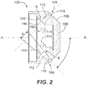
- the upstream surface 102 (identified in Fig. 2 ) of nozzle tip 100 is in fluid communication with feed passage 18 for supplying a flow of fluid to outlet orifices 104.
- feed passage 18 includes a helical flow passage defined between helical threads 24 of helical body 22 and the inner wall 26 of nozzle body 16.
- Feed passage 18 feeds fluid into the outlet orifices 104 to be issued therefrom as a spray or jet, e.g., for fuel injection.
- Fig. 4 shows nozzle body 16 with another exemplary feed passage 34 that is annular, i.e., annular feed passage 34 is defined between centre body 32 and inner wall 26.
- annular feed passage 34 is defined between centre body 32 and inner wall 26.
- a heat shield 28 is disposed downstream of the downstream surface 106 of the nozzle tip 100.
- a respective aperture 30 is defined through heat shield 28, aligned with each outlet orifice 104 to permit issue of fluid from the orifice therethrough without interference from heat shield 28.
- nozzle tip 100 includes a nozzle tip body 108 defining upstream surface 102 and the opposed downstream surface 106.
- Outlet orifices 104 are defined through nozzle tip body 108 for fluid communication from a space upstream of the upstream surface 102 (e.g., from feed passage 18) to a space downstream of downstream surface 106, e.g., a combustion chamber as in the combustor of a gas turbine engine.
- Each outlet orifice includes a cylindrical outlet portion 110 defining an outlet axis (indicated with broken lines in Fig. 2 ), and a tapered inlet portion 112 upstream of the outlet portion 110. The tapered inlet portion 112 converges down towards the outlet axis in a direction from the upstream surface 102 toward the downstream surface 106.
- the outlet axes of the outlet orifices diverge away from a central longitudinal axis A defined by the nozzle tip body 108 to issue a diverging spray pattern.
- the tapered inlet 112 converges down toward the outlet axis at an angle ⁇ less than or equal to 30° and greater than or equal to 10°.
- the tapered inlet portion meets the upstream surface at an orifice inlet edge 114 with a circumference.
- the orifice inlet edge 114 of each outlet orifice 104 defines an obtuse angle ⁇ between the tapered inlet portion and the upstream surface around the full circumference of the orifice inlet edge 114.
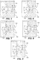
- FIG. 5 to 7 show three exemplary embodiments of orifices 104 with an angle ⁇ of greater than or equal to 10°.
- Figs. 11 to 13 show exemplary embodiments of orifices 104 with angles ⁇ of less than or equal to 30°.
- Figs. 8 to 10 show exemplary embodiments of orifices 104 with angles ⁇ between 10° and 30°.
- the axial length proportions of tapered inlet 112 and cylindrical outlet 110 can be varied.
- the tapered inlet portion 112 extends from the orifice inlet edge 114 to the cylindrical outlet portion 110, e.g., so the two portions 110 and 112 meet at an edge 116.
- the tapered inlet portion 110 can extend over a length /that is over half way along the length L of the outlet orifice 104 between the upstream surface 102 and the downstream surface 106, e.g., I / L > 0.50.
- I / L 0.50
- the tapered inlet portion 112 can extend over three-quarters of the way along the length L of the outlet orifice 104 between the upstream surface 102 and the downstream surface 106, e.g., I / L > 0.75. As shown in Figs. 6, 9 , and 12 , the tapered inlet portion 112 can extend between half of the way and three-quarters of the way along the length L of the outlet orifice 104 between the upstream surface 102 and the downstream surface 106, e.g., 0.5 ⁇ I / L ⁇ 0.75.
- a method of forming a nozzle tip includes forming a nozzle tip body, e.g., nozzle tip body 208 with opposed upstream and downstream surfaces, e.g., surfaces 202 and 206.
- the method includes forming a plurality of outlet orifices, e.g., orifices 204, through the nozzle tip body on respective orifice axes (indicate in Figs. 14 and 15 with dashed lines) that are angled diverge away from a central longitudinal axis A in a downstream direction, as indicated in Fig. 14 with broken lines.
- the cylindrical portions, e.g., cylindrical outlet portions 110 described above, of the outlet orifices can be formed by any suitable process, e.g., cutting or electrical discharge machining (EDM).
- EDM electrical discharge machining
- a tapered inlet portion, e.g., tapered inlet portions 112 described above, are formed upstream of the cylindrical outlet portions.
- Fig. 14 shows nozzle tip body 208 after the cylindrical portions are formed but before the tapered inlet portions are formed
- Fig. 15 shows nozzle tip body 208 with tapered inlet portions formed. As indicated schematically in Fig.
- each outlet orifice can include forming the tapered inlet portion with an EDM tool, e.g., tool 250, extending through the cylindrical outlet portion, e.g., extending from the space downstream of downstream surface 206, through orifice 204, and into the space upstream of upstream surface 202.
- an EDM tool e.g., tool 250
- forming each outlet orifice 204 can include forming the tapered inlet portion in a downstream portion 252 of the nozzle tip body 208 with a cutting tool extending from an upstream position, e.g. from the space upstream of upstream surface 202, along an orifice axis.
Landscapes
- Engineering & Computer Science (AREA)
- Chemical & Material Sciences (AREA)
- Combustion & Propulsion (AREA)
- Mechanical Engineering (AREA)
- General Engineering & Computer Science (AREA)
- Nozzles (AREA)
Applications Claiming Priority (1)
| Application Number | Priority Date | Filing Date | Title |
|---|---|---|---|
| US15/003,561 US20170211480A1 (en) | 2016-01-21 | 2016-01-21 | Discrete jet orifices |
Publications (1)
| Publication Number | Publication Date |
|---|---|
| EP3196554A1 true EP3196554A1 (de) | 2017-07-26 |
Family
ID=57868046
Family Applications (1)
| Application Number | Title | Priority Date | Filing Date |
|---|---|---|---|
| EP17151800.4A Withdrawn EP3196554A1 (de) | 2016-01-21 | 2017-01-17 | Diskrete strahlenöffnungen |
Country Status (2)
| Country | Link |
|---|---|
| US (2) | US20170211480A1 (de) |
| EP (1) | EP3196554A1 (de) |
Cited By (1)
| Publication number | Priority date | Publication date | Assignee | Title |
|---|---|---|---|---|
| EP4524471A1 (de) * | 2023-09-14 | 2025-03-19 | Pratt & Whitney Canada Corp. | Brennstoffdüse für ein flugzeugtriebwerk |
Families Citing this family (4)
| Publication number | Priority date | Publication date | Assignee | Title |
|---|---|---|---|---|
| US11060460B1 (en) * | 2019-04-01 | 2021-07-13 | Marine Turbine Technologies, LLC | Fuel distribution system for gas turbine engine |
| DE102019110258A1 (de) * | 2019-04-15 | 2020-10-15 | Deutsches Zentrum für Luft- und Raumfahrt e.V. | Injektorvorrichtung für eine Triebwerksvorrichtung, Triebwerksvorrichtung und Luft- und/oder Raumfahrzeug |
| US11117155B2 (en) * | 2019-10-04 | 2021-09-14 | Delavan Inc. | Fluid nozzles with heat shielding |
| US12584632B2 (en) * | 2023-10-27 | 2026-03-24 | Rtx Corporation | Modular injector bolt for an engine |
Citations (11)
| Publication number | Priority date | Publication date | Assignee | Title |
|---|---|---|---|---|
| DE933235C (de) * | 1950-08-25 | 1955-09-22 | Otto Dipl-Ing Haessler | Zerstaeuberduese fuer Schaedlingsbekaempfungsspritzen |
| US3756106A (en) * | 1971-03-01 | 1973-09-04 | Bendix Corp | Nozzle for producing fluid cutting jet |
| US4578164A (en) * | 1983-08-24 | 1986-03-25 | Nissan Motor Co., Ltd. | Method of electrolytically finishing spray-hole of fuel injection nozzle |
| JPH05231271A (ja) * | 1992-02-26 | 1993-09-07 | Isuzu Motors Ltd | 燃料噴射ノズル |
| DE10105674A1 (de) * | 2001-02-08 | 2002-08-29 | Siemens Ag | Kraftstoffeinspritzdüse für eine Brennkraftmaschine |
| US7251940B2 (en) | 2004-04-30 | 2007-08-07 | United Technologies Corporation | Air assist fuel injector for a combustor |
| EP2629016A2 (de) * | 2012-02-16 | 2013-08-21 | Delavan Inc. | Mehrpunkteinspritzung mit verstellbarem Winkel |
| US20130291546A1 (en) * | 2011-01-31 | 2013-11-07 | Snecma | Injection device for a turbine engine combustion chamber |
| US20140090394A1 (en) * | 2012-09-28 | 2014-04-03 | Kevin Joseph Low | Flow modifier for combustor fuel nozzle tip |
| US20140166143A1 (en) | 2012-12-13 | 2014-06-19 | Delavan Inc. | Flow through cylindrical bores |
| US20140203109A1 (en) * | 2013-01-18 | 2014-07-24 | Efi Hightech Ag | Injection nozzle for an internal combustion engine |
Family Cites Families (7)
| Publication number | Priority date | Publication date | Assignee | Title |
|---|---|---|---|---|
| GB8817774D0 (en) * | 1988-07-26 | 1988-09-01 | Lucas Ind Plc | Fuel injectors for i c engines |
| US6644565B2 (en) * | 1998-10-15 | 2003-11-11 | Robert Bosch Gmbh | Fuel injection nozzle for self-igniting internal combustion engines |
| DE10132449A1 (de) * | 2001-07-04 | 2003-01-23 | Bosch Gmbh Robert | Kraftstoffeinspritzventil für Brennkraftmaschinen |
| US6892962B2 (en) * | 2001-10-29 | 2005-05-17 | Combustion Components Associates, Inc. | Fuel oil atomizer and method for atomizing fuel oil |
| US7964817B2 (en) * | 2007-05-17 | 2011-06-21 | Aa Edm Corporation | Electrical discharge machine apparatus for reverse taper bores |
| GB0712403D0 (en) * | 2007-06-26 | 2007-08-01 | Delphi Tech Inc | A Spray Hole Profile |
| US8272218B2 (en) * | 2008-09-24 | 2012-09-25 | Siemens Energy, Inc. | Spiral cooled fuel nozzle |
-
2016
- 2016-01-21 US US15/003,561 patent/US20170211480A1/en not_active Abandoned
-
2017
- 2017-01-17 EP EP17151800.4A patent/EP3196554A1/de not_active Withdrawn
-
2019
- 2019-11-07 US US16/676,855 patent/US20200072129A1/en not_active Abandoned
Patent Citations (11)
| Publication number | Priority date | Publication date | Assignee | Title |
|---|---|---|---|---|
| DE933235C (de) * | 1950-08-25 | 1955-09-22 | Otto Dipl-Ing Haessler | Zerstaeuberduese fuer Schaedlingsbekaempfungsspritzen |
| US3756106A (en) * | 1971-03-01 | 1973-09-04 | Bendix Corp | Nozzle for producing fluid cutting jet |
| US4578164A (en) * | 1983-08-24 | 1986-03-25 | Nissan Motor Co., Ltd. | Method of electrolytically finishing spray-hole of fuel injection nozzle |
| JPH05231271A (ja) * | 1992-02-26 | 1993-09-07 | Isuzu Motors Ltd | 燃料噴射ノズル |
| DE10105674A1 (de) * | 2001-02-08 | 2002-08-29 | Siemens Ag | Kraftstoffeinspritzdüse für eine Brennkraftmaschine |
| US7251940B2 (en) | 2004-04-30 | 2007-08-07 | United Technologies Corporation | Air assist fuel injector for a combustor |
| US20130291546A1 (en) * | 2011-01-31 | 2013-11-07 | Snecma | Injection device for a turbine engine combustion chamber |
| EP2629016A2 (de) * | 2012-02-16 | 2013-08-21 | Delavan Inc. | Mehrpunkteinspritzung mit verstellbarem Winkel |
| US20140090394A1 (en) * | 2012-09-28 | 2014-04-03 | Kevin Joseph Low | Flow modifier for combustor fuel nozzle tip |
| US20140166143A1 (en) | 2012-12-13 | 2014-06-19 | Delavan Inc. | Flow through cylindrical bores |
| US20140203109A1 (en) * | 2013-01-18 | 2014-07-24 | Efi Hightech Ag | Injection nozzle for an internal combustion engine |
Cited By (1)
| Publication number | Priority date | Publication date | Assignee | Title |
|---|---|---|---|---|
| EP4524471A1 (de) * | 2023-09-14 | 2025-03-19 | Pratt & Whitney Canada Corp. | Brennstoffdüse für ein flugzeugtriebwerk |
Also Published As
| Publication number | Publication date |
|---|---|
| US20200072129A1 (en) | 2020-03-05 |
| US20170211480A1 (en) | 2017-07-27 |
Similar Documents
| Publication | Publication Date | Title |
|---|---|---|
| US20200072129A1 (en) | Discrete jet orifices | |
| DE60027288T2 (de) | Brennstoffeinspritzventilsitz mit einer scharfen kante | |
| US8672239B2 (en) | Fuel injector | |
| US12194558B2 (en) | Electrical discharge machining method for generating variable spray-hole geometry | |
| US20100108776A1 (en) | Adjustable cold spray nozzle | |
| US20130001325A1 (en) | Solid cone nozzle | |
| EP2626626A2 (de) | Verbesserter Flüssigbrennstoffverwirbler | |
| US20200238309A1 (en) | High velocity fluid nozzle | |
| EP3054219B1 (de) | Luftummantelungen mit luftspülung | |
| JP5787408B2 (ja) | スプレーガン | |
| US20180202655A1 (en) | Flow through cylindrical bores | |
| US8608093B2 (en) | Fuel injector having a high-pressure inlet | |
| US11560868B2 (en) | Injector for injecting a fluid, having a tapering inflow area of a through-opening | |
| CN109277217B (zh) | 一种带花瓣形喷孔的喷嘴 | |
| US20180251900A1 (en) | Device for hvof spraying process having a hot gas section insert | |
| KR20180054479A (ko) | 개선된 스프레이 상을 가진 유체를 분사하기 위한 분사기 | |
| EP4067747B1 (de) | Turbinentriebwerk-kraftstoffeinspritzdüse mit mehreckigem düsenkanal | |
| EP3499127A1 (de) | Konischer schraubenförmiger kraftstoffverteiler | |
| JP3592142B2 (ja) | 内燃機関用燃料噴射弁 | |
| JP2002306992A (ja) | 噴霧ノズル | |
| KR0179440B1 (ko) | 워터 제트룸용 씨실넣기 노즐 | |
| EP3319755B1 (de) | Düsenspitzenherstellung | |
| JP2005536362A (ja) | 構成部品の縁部に液体浸食で丸味付けするための方法及び装置 | |
| CN204186518U (zh) | 一种多喷孔铅笔型喷油器 | |
| EP2946812A1 (de) | Wirblerdüsenanordnung |
Legal Events
| Date | Code | Title | Description |
|---|---|---|---|
| PUAI | Public reference made under article 153(3) epc to a published international application that has entered the european phase |
Free format text: ORIGINAL CODE: 0009012 |
|
| STAA | Information on the status of an ep patent application or granted ep patent |
Free format text: STATUS: THE APPLICATION HAS BEEN PUBLISHED |
|
| AK | Designated contracting states |
Kind code of ref document: A1 Designated state(s): AL AT BE BG CH CY CZ DE DK EE ES FI FR GB GR HR HU IE IS IT LI LT LU LV MC MK MT NL NO PL PT RO RS SE SI SK SM TR |
|
| AX | Request for extension of the european patent |
Extension state: BA ME |
|
| STAA | Information on the status of an ep patent application or granted ep patent |
Free format text: STATUS: REQUEST FOR EXAMINATION WAS MADE |
|
| 17P | Request for examination filed |
Effective date: 20180126 |
|
| RBV | Designated contracting states (corrected) |
Designated state(s): AL AT BE BG CH CY CZ DE DK EE ES FI FR GB GR HR HU IE IS IT LI LT LU LV MC MK MT NL NO PL PT RO RS SE SI SK SM TR |
|
| STAA | Information on the status of an ep patent application or granted ep patent |
Free format text: STATUS: EXAMINATION IS IN PROGRESS |
|
| 17Q | First examination report despatched |
Effective date: 20190206 |
|
| STAA | Information on the status of an ep patent application or granted ep patent |
Free format text: STATUS: THE APPLICATION HAS BEEN WITHDRAWN |
|
| 18W | Application withdrawn |
Effective date: 20210225 |