EP2629332A2 - Transistor mit erhöhter Durchbruchspannung - Google Patents
Transistor mit erhöhter Durchbruchspannung Download PDFInfo
- Publication number
- EP2629332A2 EP2629332A2 EP13153374.7A EP13153374A EP2629332A2 EP 2629332 A2 EP2629332 A2 EP 2629332A2 EP 13153374 A EP13153374 A EP 13153374A EP 2629332 A2 EP2629332 A2 EP 2629332A2
- Authority
- EP
- European Patent Office
- Prior art keywords
- finger electrode
- drain
- transistor
- source
- drain finger
- Prior art date
- Legal status (The legal status is an assumption and is not a legal conclusion. Google has not performed a legal analysis and makes no representation as to the accuracy of the status listed.)
- Granted
Links
Images



Classifications
-
- H—ELECTRICITY
- H10—SEMICONDUCTOR DEVICES; ELECTRIC SOLID-STATE DEVICES NOT OTHERWISE PROVIDED FOR
- H10D—INORGANIC ELECTRIC SEMICONDUCTOR DEVICES
- H10D30/00—Field-effect transistors [FET]
- H10D30/40—FETs having zero-dimensional [0D], one-dimensional [1D] or two-dimensional [2D] charge carrier gas channels
- H10D30/47—FETs having zero-dimensional [0D], one-dimensional [1D] or two-dimensional [2D] charge carrier gas channels having two-dimensional [2D] charge carrier gas channels, e.g. nanoribbon FETs or high electron mobility transistors [HEMT]
- H10D30/471—High electron mobility transistors [HEMT] or high hole mobility transistors [HHMT]
- H10D30/477—Vertical HEMTs or vertical HHMTs
-
- H—ELECTRICITY
- H10—SEMICONDUCTOR DEVICES; ELECTRIC SOLID-STATE DEVICES NOT OTHERWISE PROVIDED FOR
- H10D—INORGANIC ELECTRIC SEMICONDUCTOR DEVICES
- H10D64/00—Electrodes of devices having potential barriers
- H10D64/20—Electrodes characterised by their shapes, relative sizes or dispositions
- H10D64/23—Electrodes carrying the current to be rectified, amplified, oscillated or switched, e.g. sources, drains, anodes or cathodes
- H10D64/251—Source or drain electrodes for field-effect devices
- H10D64/257—Source or drain electrodes for field-effect devices for lateral devices wherein the source or drain electrodes are characterised by top-view geometrical layouts, e.g. interdigitated, semi-circular, annular or L-shaped electrodes
-
- H—ELECTRICITY
- H10—SEMICONDUCTOR DEVICES; ELECTRIC SOLID-STATE DEVICES NOT OTHERWISE PROVIDED FOR
- H10D—INORGANIC ELECTRIC SEMICONDUCTOR DEVICES
- H10D64/00—Electrodes of devices having potential barriers
- H10D64/20—Electrodes characterised by their shapes, relative sizes or dispositions
- H10D64/27—Electrodes not carrying the current to be rectified, amplified, oscillated or switched, e.g. gates
- H10D64/311—Gate electrodes for field-effect devices
- H10D64/411—Gate electrodes for field-effect devices for FETs
-
- H—ELECTRICITY
- H10—SEMICONDUCTOR DEVICES; ELECTRIC SOLID-STATE DEVICES NOT OTHERWISE PROVIDED FOR
- H10D—INORGANIC ELECTRIC SEMICONDUCTOR DEVICES
- H10D64/00—Electrodes of devices having potential barriers
- H10D64/20—Electrodes characterised by their shapes, relative sizes or dispositions
- H10D64/27—Electrodes not carrying the current to be rectified, amplified, oscillated or switched, e.g. gates
- H10D64/311—Gate electrodes for field-effect devices
- H10D64/411—Gate electrodes for field-effect devices for FETs
- H10D64/511—Gate electrodes for field-effect devices for FETs for IGFETs
- H10D64/517—Gate electrodes for field-effect devices for FETs for IGFETs characterised by the conducting layers
- H10D64/519—Gate electrodes for field-effect devices for FETs for IGFETs characterised by the conducting layers characterised by their top-view geometrical layouts
-
- H—ELECTRICITY
- H10—SEMICONDUCTOR DEVICES; ELECTRIC SOLID-STATE DEVICES NOT OTHERWISE PROVIDED FOR
- H10D—INORGANIC ELECTRIC SEMICONDUCTOR DEVICES
- H10D30/00—Field-effect transistors [FET]
- H10D30/40—FETs having zero-dimensional [0D], one-dimensional [1D] or two-dimensional [2D] charge carrier gas channels
- H10D30/47—FETs having zero-dimensional [0D], one-dimensional [1D] or two-dimensional [2D] charge carrier gas channels having two-dimensional [2D] charge carrier gas channels, e.g. nanoribbon FETs or high electron mobility transistors [HEMT]
- H10D30/471—High electron mobility transistors [HEMT] or high hole mobility transistors [HHMT]
- H10D30/475—High electron mobility transistors [HEMT] or high hole mobility transistors [HHMT] having wider bandgap layer formed on top of lower bandgap active layer, e.g. undoped barrier HEMTs such as i-AlGaN/GaN HEMTs
- H10D30/4755—High electron mobility transistors [HEMT] or high hole mobility transistors [HHMT] having wider bandgap layer formed on top of lower bandgap active layer, e.g. undoped barrier HEMTs such as i-AlGaN/GaN HEMTs having wide bandgap charge-carrier supplying layers, e.g. modulation doped HEMTs such as n-AlGaAs/GaAs HEMTs
-
- H—ELECTRICITY
- H10—SEMICONDUCTOR DEVICES; ELECTRIC SOLID-STATE DEVICES NOT OTHERWISE PROVIDED FOR
- H10D—INORGANIC ELECTRIC SEMICONDUCTOR DEVICES
- H10D30/00—Field-effect transistors [FET]
- H10D30/60—Insulated-gate field-effect transistors [IGFET]
Definitions
- group III-V refers to a compound semiconductor that includes a group V element and at least one group III element.
- III-Nitride refers to a compound semiconductor that includes nitrogen (N) and at least one group III element, including aluminum (Al), gallium (Ga), indium (In), and boron (B), and including but not limited to any of its alloys, such as aluminum gallium nitride (Al x Ga (1-x) N), indium gallium nitride (In y Ga (1-y) N), aluminum indium gallium nitride (Al x In y Ga (1-x-y )N), gallium arsenide phosphide nitride (GaAs a P b N (1-a-b) ), and aluminum indium gallium arsenide phosphide nitride (Al x In y Ga (1-x-y) As a P b N (1-a)
- III-Nitride also refers generally to any polarity including but not limited to Ga-polar, N-polar, semi-polar or non-polar crystal orientations.
- a III-Nitride material may also include either the Wurtzitic, Zincblende, or mixed polytypes, and may include single-crystal, monocrystalline, polycrystalline, or amorphous structures.
- Group III-V heterostructure field-effect transistors such as group III-V high electron mobility transistors (group III-V HEMTs) are often utilized in high power switching applications.
- group III-V HEMTs group III-V high electron mobility transistors
- III-Nitride HEMTs may be utilized to provide switching and/or amplification functions.
- Group III-V HFETs advantageously allow implementation of power transistors using a lateral conduction topology in which the drain, source, and gate electrodes are formed on one side of a semiconductor wafer or die.
- drain and source finger electrodes coupled to respective drain and source pads may be interdigitated and surrounded by a gate region.
- the transistors are fabricated with a higher unit cell density.
- the gate-to-drain spacing at the drain finger electrode ends of higher density power transistors may be insufficient to reliably sustain a high breakdown voltage.
- the present disclosure is directed to a transistor having a decreased electric field at the ends or tips of the drain finger electrodes by increasing the radius of curvature of the drain finger electrode ends, thereby allowing for an increased breakdown voltage and a more robust and reliable transistor, substantially as shown in and/or described in connection with at least one of the figures, and as set forth more completely in the claims.
- Figure 1 presents a top plan view of conventional transistor 100.
- Conventional transistor 100 has active surface 102 including source pad 104, drain pad 106, and gate pad 108.
- Conventional transistor 100 also includes gate region 109 adjoining gate pad 108, source finger electrodes 111, drain finger electrodes 121, and field dielectric 107 isolating source finger electrodes 111 and drain finger electrodes 121 from gate region 109.
- Source finger electrodes 111 are electrically coupled to source pad 104
- drain finger electrodes 121 are electrically coupled to drain pad 106.
- drain finger electrodes 121 are terminated adjacent source pad 104 by being simply rounded off to form semicircular drain finger electrode ends 125.
- the electrical coupling of source finger electrodes 111 and drain finger electrodes 121 to respective source pad 104 and drain pad 106 is shown by dashed lines because those connections may be formed using one or more additional metal layers not shown in Figure 1 .
- Source finger electrodes 111 and drain finger electrodes 121 are situated in gate region 109 and are implemented in an interdigitated pattern such that gate region 109 surrounds source finger electrodes 111 and drain finger electrodes 121, and is disposed between the interdigitated source finger electrodes 111 and drain finger electrodes 121.
- conventional transistor 100 has source-to-drain half-pitch 135, i.e., the distance separating center line 131 of source finger electrode 111 from center line 132 of drain finger electrode 121.
- Conventional transistor 100 displays a symmetrical layout commonly utilized to implement lateral power transistors. As shown in Figure 1 , source-to-drain half-pitch 135 is substantially constant along the entirety of drain finger electrodes 121. However, due to the high termination electric fields which may develop under high voltage operation, particularly at semicircular drain finger electrode ends 125, the robustness of conventional transistor 100 may be compromised. As a result, conventional transistor 100 may break down, become unstable, and/or fail catastrophically under high voltage operation.
- Figure 2 presents a top plan view of transistor 200 having an exemplary drain termination enabling reduced electric fields and increased breakdown voltage, according to one implementation.
- Figure 2 shows active surface 202 of semiconductor body 201 in which transistor 200 is fabricated.
- Transistor 200 includes drain finger electrodes 220 interdigitated with source finger electrodes 210.
- Transistor 200 may be a high voltage transistor.
- transistor 200 may take the form of a field-effect transistor (FET).
- FET field-effect transistor
- transistor 200 may be an insulated-gate FET (IGFET) or a heterostructure FET (HFET).
- HFET heterostructure FET
- transistor 200 may take the form of a metal-insulator-semiconductor FET (MISFET), such as a metal-oxide-semiconductor FET (MOSFET).
- MISFET metal-insulator-semiconductor FET
- MOSFET metal-oxide-semiconductor FET
- transistor 200 when implemented as an HFET, transistor 200 may be a high electron mobility transistor (HEMT) producing a two-dimensional electron gas (2DEG).
- HEMT high electron mobility transistor
- transistor 200 may take the form of a schottky diode (not shown in Figure 2 ), for example through replacement of drain finger electrodes 220 with anode electrodes, replacement of the source finger electrodes 210 with cathode electrodes, and without the controlling gate electrode of Figure 2 .
- III-Nitride materials include gallium nitride (GaN) and/or its alloys, such as aluminum gallium nitride (AlGaN), indium gallium nitride (InGaN), and aluminum indium gallium nitride (AlInGaN). These materials are semiconductor compounds that have a relatively wide, direct bandgap and strong piezoelectric polarizations, and can enable high breakdown fields, and the creation of 2DEGs. As a result, III-Nitride materials such as GaN are used in many microelectronic applications in which high power density and high efficiency switching are required.
- Active surface 202 of transistor 200 includes source pad 204, drain pad 206, and gate pad 208.
- transistor 200 also includes gate region 209, and field dielectric 207.
- Source finger electrodes 210 are electrically coupled to source pad 204
- drain finger electrodes 220 are electrically coupled to drain pad 206
- gate region 209 is electrically coupled to gate pad 208. It is noted that the electrical coupling of source finger electrodes 210 to source pad 204 and that of gate region 209 to gate pad 208 is shown by dashed lines because those connections may be formed using one or more additional metal layers not shown in Figure 2 .
- source pad 204 and drain pad 206 may be on the same plane as source finger electrodes 210 and drain finger electrodes 220. However, in other implementations, source pad 204 and/or drain pad 206 may be on a different plane than that occupied by source finger electrodes 210 and/or drain finger electrode 220. For example, source pad 204 and/or drain pad 206 may be formed on a backside of the device or substrate and electrically connected to their respectively corresponding finger electrodes using electrical through-substrate vias. Such transistor designs with ohmic pad (source and/or drain) construction on other planes are described in U.S.
- Patent Number 7,233,028 entitled “Gallium Nitride Material Devices and Methods of Forming the Same," and issued on June 19, 2007; and in U.S. Patent Number 7,915,645 , entitled “Monolithic Vertically Integrated Composite Group III-V and Group IV Semiconductor Device and Method for Fabricating Same," and issued on March 29, 2011.
- the entire disclosures of U.S. Patent Number 7,233,028 and U.S. Patent Number 7,915,645 are hereby incorporated fully by reference into the present application.
- source finger electrodes 210 and drain finger electrodes 220 may be implemented in an interdigitated pattern such that gate region 209 surrounds source finger electrodes 210 and is between interdigitated source finger electrodes 210 and drain finger electrodes 220.
- Source finger electrodes 210 have length 212
- drain finger electrodes 220 have length 222.
- source-to-drain half-pitch 235 of transistor 200 i.e., the distance separating center line 231 of source finger electrode 210 from center line 232 of drain finger electrode 220.
- Source finger electrodes 210 have source finger electrode beginnings 214 coupled to source pad 204, and source finger electrode ends 216 adjacent drain pad 206.
- Drain finger electrodes 220 have drain finger electrode beginnings 224 coupled to drain pad 206, and curved drain finger electrode ends or tips 226 adjacent source pad 204.
- source-to-drain half-pitch 235 of transistor 200 is substantially constant from source finger electrode beginnings 214 to source finger electrode ends 216.
- curved drain finger electrode ends 226 are modified in order reduce the electric field at the tips of drain finger electrodes 220.
- curved drain finger electrode ends 226 have an increased radius of curvature, such as (r1) 236, for example, resulting in increased width 246 of curved drain finger electrode ends 226 relative to width 254 of drain finger electrode 220. It is noted that as used herein, width 254 is defined as the width of drain finger electrode 220 just before the transition to curved drain finger electrode end 226.
- radius of curvature (r2) 241 of gate region 209 surrounding curved drain finger electrode end 226 is also increased, which increases the gate-to-drain spacing (d2) 257 in the vicinity of curved drain finger electrode ends 226 compared to the gate-to-drain spacing (d1) 267, further reducing the electric field at curved drain finger electrode ends 226. It is noted that for the purposes of the present application, when curved drain finger electrode ends 226 are described as having an increased radius of curvature, that characterization can apply to either one, or both, of (r1 236 and (r2) 241.
- increased radius of curvature (r1) 236 of curved drain finger electrode ends 226 may cause curved drain finger electrode ends 226 to have a generally ellipsoidal shape as discussed in more detail in reference to Figures 3A, 3B , and 4 , below.
- curved drain finger electrode ends 226 as substantial ellipsoids is that such a shape can aid in reducing or relaxing the high termination electrical fields that can otherwise exist at semicircular drain finger electrode ends 125 of conventional transistor 100, shown in Figure 1 .
- curved drain finger electrode ends 226 are extended beyond source finger electrode beginnings 214.
- curved drain finger electrode ends 226 may be situated closer to source pad 204 than source finger electrode beginnings 214. Extension of curved drain finger electrode ends 226 beyond source finger electrode beginnings 214 can advantageously achieve an increased breakdown voltage for transistor 200 without increasing source-to-drain half-pitch 235 along length 212 of source finger electrodes 210. Consequently, the exemplary transistor layout shown in Figure 2 can be implemented so as to allow for a tighter source-to-drain half-pitch while achieving increased breakdown voltage, thereby providing a low ON-resistance and improved performance for transistor 200, concurrently.
- drain finger electrodes 220 depicts drain finger electrodes 220 as having increased radius of curvature (r1) 236, increased radius of curvature (r2) 241, and increased width 246 at curved drain finger electrode ends 226, as well as having curved drain finger electrode ends 226 extending beyond source finger electrode beginnings 214, that representation is merely exemplary. In other implementations, drain finger electrodes 220 may not have all of those characteristics concurrently. For example, in one implementation, curved drain finger electrode ends 226 may extend beyond source finger electrode beginnings 214 but not have increased radius of curvature (r1) 236, increased radius of curvature (r2) 241, or increased width 246.
- curved drain finger electrode ends 226 may have increased radius of curvature (r1) 236, increased width 246, and/or increased radius of curvature (r2) 241, but may not extend beyond source finger electrode beginnings 214.
- drain finger electrodes 220 may have length 222 greater than length 212 of source finger electrodes 210, and/or may have curved drain finger electrode ends 226 extending beyond source finger electrode beginnings 214, and/or may have increased radius of curvature (r1) 236, increased width 246, and/or increased radius of curvature (r2) 241 at curved drain finger electrode ends 226.
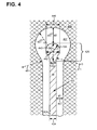
- Figures 3A, 3B , and 4 present respective top plan views of exemplary drain terminations having a decreased electric field at the ends or tips of the drain finger electrodes.
- a decreased electric field can result from increasing a radius of curvature of the gate-to-drain spacing between an edge of a curved drain finger electrode end and a boundary of a gate region surrounding the curved drain finger electrode end, thereby allowing for an increased breakdown voltage and a more robust and reliable transistor.
- the exemplary implementations shown in Figures 3A, 3B , and 4 corresponding in general to the implementation shown in Figure 2 .
- Figure 3A is an example of an actual layout used for the drain finger termination according to one implementation.
- Figure 3A shows a portion of gate region 309 surrounding drain finger electrode 320.
- Source finger electrodes 310 with which drain finger electrode 320 is interdigitated, and field dielectric 307.
- Gate region 309, drain finger electrode 320, source finger electrodes 310, and field dielectric 307 correspond respectively to gate region 209, drain finger electrodes 220, source finger electrodes 210, and field dielectric 207, in Figure 2 .
- Figure 3A shows the relative width of drain finger electrode 320 compared to source finger electrodes 210, as well as the smooth transitions at the curved end of drain finger electrode 320. It is noted that there are no sharp discontinuities in the curvature of the drain finger electrode end. In addition, and as further shown by Figure 3A , there are no sharp discontinuities at the boundary of field dielectric 307 with gate region 309, which also aids in reducing the electric fields at the end of drain finger electrode 320.
- Figure 3B shows gate region 309 surrounding drain finger electrode 320.
- Drain finger electrode 320 has width 354, and also includes drain finger electrode beginning 324 having width 334.
- Figure 3B shows curved drain finger electrode end 326 having increased radius of curvature (r1) 336 relative to the radius of curvature of semicircular drain finger electrode ends 125 in conventional transistor 100 of Figure 1 . That is to say, in contrast to conventional transistor 100 having semicircular drain finger ends 125, radius of curvature (r1) 336 of curved drain finger end 326 is greater than a radius of curvature of a circle having a diameter equal to width 354.
- radius of curvature (r2) 341 of the gate electrode region surrounding the drain finger electrode end 326 is also shown in Figure 3B.
- radius of curvature (r3) 371 of the smooth transition connecting curved drain finger electrode end 326 to drain finger electrode 320 is also shown in Figure 3B.
- Figure 3B further depicts gate-to-drain spacing (d1) 367, gate-to-drain spacing (d2) 357, and length 322 of drain finger electrode 320.
- Gate-to-drain spacing (d1) 367, gate-to-drain spacing (d2) 357, length 322, and width 354, correspond respectively to gate-to-drain spacing (d1) 267, gate-to-drain spacing (d2) 257, length 222, and width 254, in Figure 2 .
- curved drain finger electrode end 326, radius of curvature (r1) 336, and radius of curvature (r2) 341, in Figure 3B correspond respectively to curved drain finger electrode ends 226, radius of curvature (r1) 236, and radius of curvature (r2) 241, in Figure 2 .
- gate-to-drain spacing (d1) 367 is shown as being less than gate-to-drain spacing (d2) 357.
- curved drain finger electrode end 326 when curved drain finger electrode end 326 is described as having an increased radius of curvature, that characterization can apply to any one of (r1) 336, (r2) 341, (r3) 371, or (r4) 381, as well as to any combination of (r1) 336, (r2) 341, (r3) 371, and (r4) 381.
- Figure 4 shows gate region 409 surrounding drain finger electrode 420.
- Drain finger electrode 420 has width 454 and includes drain finger electrode beginning 424 having width 434.
- drain finger electrode 420 has curved drain finger electrode end 426 with increased width 446 relative to width 454 of drain finger electrode 420.
- field dielectric 407 radius of curvature (r1) 436, radius of curvature (r2) 441, radius of curvature (r3) 471, radius of curvature (r4) 481, gate-to-drain spacing (d1) 467, and gate-to-drain spacing (d2) 457, as well as minor axis 442 and major axis 443 of curved drain finger electrode end 426.
- Gate region 409, field dielectric 407, and drain finger electrode 420 correspond respectively to gate region 309, field dielectric 307, and drain finger electrode 320, in Figures 3A and 3B .
- width 454, curved drain finger electrode end 426, and drain finger electrode beginning 424 having width 434 correspond respectively to width 354, curved drain finger electrode end 326, and drain finger electrode beginning 324 having width 334, in Figure 3B .
- gate-to-drain spacings (d1) 467 and (d2) 457, and radii of curvature (r1) 436, (r2) 441, (r3) 471, and (r4) 481, in Figure 4 correspond respectively to gate-to-drain spacings (d1) 367 and (d2) 357, and radii of curvature (r1) 236, (r2) 241, (r3) 371, and (r4) 381, in Figure 3B .
- increased width 446 of curved drain finger electrode end 426, in Figure 4 corresponds to increased width 246 of curved drain finger electrode end 226, in Figure 2 .
- curved drain finger electrode end 426 has a shape described by major axis 443 and minor axis 442.
- Major axis 443 is longer than and substantially perpendicular to minor axis 442.
- major axis 443 is substantially aligned with drain finger electrode 420, and minor axis 442 is substantially perpendicular to drain finger electrode 420.
- curved drain finger electrode end 426 may be substantially an ellipsoid having major axis 443 substantially aligned with drain finger electrode 420.
- Curved drain finger electrode end 426 taking the form of an ellipsoid with major axis 443 and minor axis 442 results from forming curved drain finger electrode end 426 and the surrounding gate region 409 with increased radii of curvature (r1) 436, r2 (441), r3 (471), and r4 (481) such that r1 ⁇ r2 ⁇ r4.
- both r3 and r4 radii of curvature are optimized to have a smooth curvature with no sharp discontinuities where they meet drain finger electrode 420 and gate region 409 surrounding drain finger electrode 420, respectively.
- Gate-to-drain spacing (d1) 467 is shown as being less than gate-to-drain spacing (d2) 457.
- d1 ⁇ d2 in combination with the ellipsoidal shape of curved drain finger electrode end 426, and the smooth curvatures created by radii of curvature r1, r2, r3, and r4, allows for the formation of a more robust drain finger electrode termination.
- the ratio of increased width 446 to width 454 may be approximately equal to 2:1. In other implementations, it may be advantageous or desirable for the ratio of increased width 446 to width 454 to be greater than 2:1.
- An advantage of using an ellipsoidal shape for curved drain finger electrode end 426 is that such a shape can aid in reducing or relaxing the high termination electric fields that can otherwise be present at the termination of a conventionally configured drain finger electrode, such as semicircular drain finger electrode ends 125, in Figure 1 .
- drain finger electrode 420 is not drawn to scale. Nevertheless, drain finger electrode 420 corresponds to drain finger electrodes 220 in Figure 2 , as well as to drain finger electrode 320 in Figures 3A and 3B , as noted above.
- tapered drain and source finger electrodes which may be implemented in combination with a curved drain finger electrode end having an increased radius of curvature, corresponding to curved drain finger electrode ends 226/326/426 in respective Figures 2 , 3B , and 4 .
- Such tapered source and drain finger designs are described in U.S. Patent Number 7,417,257 , entitled “III-Nitride Device with Improved Layout Geometry,” and issued on August 26, 2008. The entire disclosure of U.S. Patent Number 7,417,257 is hereby incorporated fully by reference into the present application.
- Figure 5 depicts an exemplary implementation of a tapered drain finger electrode design.
- Figure 5 shows gate region 509 surrounding tapered drain finger electrode 520.
- Tapered drain finger electrode 520 has width 554, and includes a tapered drain finger electrode beginning 524 having width 534.
- tapered drain finger electrode 520 includes curved drain finger electrode end 526 with increased radius of curvature (r1) 536 relative to the radius of curvature of semicircular drain finger electrode ends 125 in conventional transistor 100 of Figure 1 . That is to say, in contrast to conventional transistor 100 having semicircular drain finger ends 125, radius of curvature (r1) 536 of curved drain finger electrode end 526 is greater than a radius of curvature of a circle having a diameter equal to width 554.
- width 534 of tapered drain finger electrode beginning 524 is larger than width 554.
- tapered drain finger electrode 520 has a tapered drain finger electrode beginning width 534 that is greater than width 554.
- implementations dislcosed by the present application result in a reduced termination electric field at the curved drain finger electrode ends.
- the disclosed implementations achieve an increased breakdown voltage for the transistor.
- implementations dislcosed by the present application allow greater gate-to-drain separation at the curved drain finger ends without increasing source-to-drain half-pitch. Consequently, the implementations disclosed herein can achieve increased breakdown voltage for a transistor while concurrently maintaining a low specific ON-resistance (on-resistance in the active area) for the transistor.
Landscapes
- Junction Field-Effect Transistors (AREA)
- Electrodes Of Semiconductors (AREA)
- Insulated Gate Type Field-Effect Transistor (AREA)
Applications Claiming Priority (2)
| Application Number | Priority Date | Filing Date | Title |
|---|---|---|---|
| US201261600469P | 2012-02-17 | 2012-02-17 | |
| US13/749,477 US9379231B2 (en) | 2012-02-17 | 2013-01-24 | Transistor having increased breakdown voltage |
Publications (3)
| Publication Number | Publication Date |
|---|---|
| EP2629332A2 true EP2629332A2 (de) | 2013-08-21 |
| EP2629332A3 EP2629332A3 (de) | 2014-07-30 |
| EP2629332B1 EP2629332B1 (de) | 2018-01-17 |
Family
ID=47632881
Family Applications (1)
| Application Number | Title | Priority Date | Filing Date |
|---|---|---|---|
| EP13153374.7A Active EP2629332B1 (de) | 2012-02-17 | 2013-01-31 | Transistor mit erhöhter Durchbruchspannung |
Country Status (3)
| Country | Link |
|---|---|
| US (1) | US9379231B2 (de) |
| EP (1) | EP2629332B1 (de) |
| JP (1) | JP5722931B2 (de) |
Cited By (1)
| Publication number | Priority date | Publication date | Assignee | Title |
|---|---|---|---|---|
| CN112925137A (zh) * | 2021-03-29 | 2021-06-08 | 绵阳惠科光电科技有限公司 | 一种驱动电路的控制开关、阵列基板和显示面板 |
Families Citing this family (9)
| Publication number | Priority date | Publication date | Assignee | Title |
|---|---|---|---|---|
| JP5985282B2 (ja) * | 2012-07-12 | 2016-09-06 | ルネサスエレクトロニクス株式会社 | 半導体装置 |
| JP5948500B2 (ja) * | 2013-06-13 | 2016-07-06 | シャープ株式会社 | ヘテロ接合電界効果トランジスタ |
| JP6660631B2 (ja) | 2015-08-10 | 2020-03-11 | ローム株式会社 | 窒化物半導体デバイス |
| JP6733462B2 (ja) * | 2016-09-28 | 2020-07-29 | 日亜化学工業株式会社 | 電界効果トランジスタ |
| JP6812764B2 (ja) * | 2016-11-29 | 2021-01-13 | 日亜化学工業株式会社 | 電界効果トランジスタ |
| DE102020112069B4 (de) * | 2020-02-27 | 2022-03-03 | Taiwan Semiconductor Manufacturing Co. Ltd. | Source-leckstromunterdrückung durch source-umgebende gate-struktur und verfahren zur herstellung der gate-struktur |
| US11791388B2 (en) * | 2020-02-27 | 2023-10-17 | Taiwan Semiconductor Manufacturing Company, Ltd. | Source leakage current suppression by source surrounding gate structure |
| US12068216B1 (en) * | 2021-10-20 | 2024-08-20 | National Technology & Engineering Solutions Of Sandia, Llc | Multichannel transistor with improved gate conformation |
| CN117276325B (zh) * | 2023-11-17 | 2024-01-23 | 壹新信通科技(成都)有限公司 | 一种太赫兹二极管结构、倍频器及电子设备 |
Citations (3)
| Publication number | Priority date | Publication date | Assignee | Title |
|---|---|---|---|---|
| US7233028B2 (en) | 2001-02-23 | 2007-06-19 | Nitronex Corporation | Gallium nitride material devices and methods of forming the same |
| US7417257B2 (en) | 2003-12-05 | 2008-08-26 | International Rectifier Corporation | III-nitride device with improved layout geometry |
| US7915645B2 (en) | 2009-05-28 | 2011-03-29 | International Rectifier Corporation | Monolithic vertically integrated composite group III-V and group IV semiconductor device and method for fabricating same |
Family Cites Families (18)
| Publication number | Priority date | Publication date | Assignee | Title |
|---|---|---|---|---|
| JPH02102546A (ja) | 1988-10-12 | 1990-04-16 | Mitsubishi Electric Corp | GaAs半導体装置の製造方法 |
| JPH0677258A (ja) | 1992-08-26 | 1994-03-18 | Nec Kansai Ltd | 電界効果トランジスタ及びその製造方法 |
| JP3203858B2 (ja) | 1993-02-15 | 2001-08-27 | 富士電機株式会社 | 高耐圧mis電界効果トランジスタ |
| JP2000340580A (ja) | 1999-05-26 | 2000-12-08 | Sanken Electric Co Ltd | 半導体装置 |
| JP2001015761A (ja) | 1999-07-01 | 2001-01-19 | Casio Comput Co Ltd | 薄膜トランジスタ |
| JP4041660B2 (ja) * | 2001-05-31 | 2008-01-30 | ユーディナデバイス株式会社 | 半導体装置及びその製造方法 |
| US6919598B2 (en) * | 2003-03-10 | 2005-07-19 | Zia Hossain | LDMOS transistor with enhanced termination region for high breakdown voltage with low on-resistance |
| US20060071304A1 (en) | 2004-09-29 | 2006-04-06 | International Business Machines Corporation | Structure and layout of a fet prime cell |
| US8154079B2 (en) * | 2006-12-07 | 2012-04-10 | Kabushiki Kaisha Toshiba | Semiconductor device and fabrication method of the semiconductor device |
| GB0709706D0 (en) * | 2007-05-21 | 2007-06-27 | Filtronic Compound Semiconduct | A field effect transistor |
| JP2009111217A (ja) * | 2007-10-31 | 2009-05-21 | Toshiba Corp | 半導体装置 |
| WO2010010506A1 (en) * | 2008-07-22 | 2010-01-28 | Nxp B.V. | Ldmos having a field plate |
| US7875930B2 (en) * | 2009-02-16 | 2011-01-25 | Vanguard International Semiconductor Corporation | Semiconductor structure having an enlarged finger shaped region for reducing electric field density and method of manufacturing the same |
| JP5468286B2 (ja) | 2009-04-07 | 2014-04-09 | 株式会社東芝 | 半導体装置およびその製造方法 |
| CN102013437B (zh) * | 2009-09-07 | 2014-11-05 | 苏州捷芯威半导体有限公司 | 半导体器件及其制造方法 |
| JP5458809B2 (ja) | 2009-11-02 | 2014-04-02 | 富士電機株式会社 | 半導体装置 |
| US8969973B2 (en) | 2010-07-02 | 2015-03-03 | Win Semiconductors Corp. | Multi-gate semiconductor devices |
| JP5776143B2 (ja) * | 2010-07-06 | 2015-09-09 | サンケン電気株式会社 | 半導体装置 |
-
2013
- 2013-01-24 US US13/749,477 patent/US9379231B2/en active Active
- 2013-01-30 JP JP2013015708A patent/JP5722931B2/ja active Active
- 2013-01-31 EP EP13153374.7A patent/EP2629332B1/de active Active
Patent Citations (3)
| Publication number | Priority date | Publication date | Assignee | Title |
|---|---|---|---|---|
| US7233028B2 (en) | 2001-02-23 | 2007-06-19 | Nitronex Corporation | Gallium nitride material devices and methods of forming the same |
| US7417257B2 (en) | 2003-12-05 | 2008-08-26 | International Rectifier Corporation | III-nitride device with improved layout geometry |
| US7915645B2 (en) | 2009-05-28 | 2011-03-29 | International Rectifier Corporation | Monolithic vertically integrated composite group III-V and group IV semiconductor device and method for fabricating same |
Cited By (2)
| Publication number | Priority date | Publication date | Assignee | Title |
|---|---|---|---|---|
| CN112925137A (zh) * | 2021-03-29 | 2021-06-08 | 绵阳惠科光电科技有限公司 | 一种驱动电路的控制开关、阵列基板和显示面板 |
| CN112925137B (zh) * | 2021-03-29 | 2023-03-10 | 绵阳惠科光电科技有限公司 | 一种驱动电路的控制开关、阵列基板和显示面板 |
Also Published As
| Publication number | Publication date |
|---|---|
| US9379231B2 (en) | 2016-06-28 |
| JP2013172151A (ja) | 2013-09-02 |
| EP2629332A3 (de) | 2014-07-30 |
| JP5722931B2 (ja) | 2015-05-27 |
| US20130214330A1 (en) | 2013-08-22 |
| EP2629332B1 (de) | 2018-01-17 |
Similar Documents
| Publication | Publication Date | Title |
|---|---|---|
| EP2629332B1 (de) | Transistor mit erhöhter Durchbruchspannung | |
| US9564498B2 (en) | Transistor with elevated drain termination | |
| US9431391B2 (en) | Gallium nitride hemt device with a mosfet in series coupled to diodes for protection of high-voltage | |
| US10186591B2 (en) | Nitride semiconductor device | |
| US9397089B2 (en) | Group III-V HEMT having a selectably floating substrate | |
| TWI499058B (zh) | 氮化鎵二極體及積體組件 | |
| US9184243B2 (en) | Monolithic composite III-nitride transistor with high voltage group IV enable switch | |
| CN103930997B (zh) | 具有凹陷电极结构的半导体器件 | |
| US20080308813A1 (en) | High breakdown enhancement mode gallium nitride based high electron mobility transistors with integrated slant field plate | |
| US10475918B2 (en) | Semiconductor device and method of manufacturing the same | |
| CN103456733B (zh) | 单片集成hemt和电流保护器件 | |
| EP2363880A2 (de) | Monolithische Integration von Silizium- und III-V-Bauelementen | |
| US7737467B2 (en) | Nitride semiconductor device with a hole extraction electrode | |
| EP2629334A2 (de) | Leistungstransistor mit segmentiertem Gate | |
| US9825139B2 (en) | Semiconductor device and method | |
| CN107887448A (zh) | 半导体器件 | |
| WO2010042479A2 (en) | Enhancement-mode nitride transistor | |
| CN105264650B (zh) | 异质结场效应晶体管 | |
| US9450071B2 (en) | Field effect semiconductor devices and methods of manufacturing field effect semiconductor devices | |
| CN114188411B (zh) | 半导体装置 | |
| US20140239349A1 (en) | Drain Pad Having a Reduced Termination Electric Field | |
| US11201220B2 (en) | Semiconductor device | |
| US12513981B2 (en) | Semiconductor device | |
| WO2024171753A1 (ja) | 半導体装置 | |
| KR101559111B1 (ko) | 양방향 스위칭 소자 및 그 제조 방법 |
Legal Events
| Date | Code | Title | Description |
|---|---|---|---|
| PUAI | Public reference made under article 153(3) epc to a published international application that has entered the european phase |
Free format text: ORIGINAL CODE: 0009012 |
|
| AK | Designated contracting states |
Kind code of ref document: A2 Designated state(s): AL AT BE BG CH CY CZ DE DK EE ES FI FR GB GR HR HU IE IS IT LI LT LU LV MC MK MT NL NO PL PT RO RS SE SI SK SM TR |
|
| AX | Request for extension of the european patent |
Extension state: BA ME |
|
| PUAL | Search report despatched |
Free format text: ORIGINAL CODE: 0009013 |
|
| AK | Designated contracting states |
Kind code of ref document: A3 Designated state(s): AL AT BE BG CH CY CZ DE DK EE ES FI FR GB GR HR HU IE IS IT LI LT LU LV MC MK MT NL NO PL PT RO RS SE SI SK SM TR |
|
| AX | Request for extension of the european patent |
Extension state: BA ME |
|
| RIC1 | Information provided on ipc code assigned before grant |
Ipc: H01L 29/778 20060101ALI20140623BHEP Ipc: H01L 29/423 20060101ALI20140623BHEP Ipc: H01L 29/417 20060101AFI20140623BHEP |
|
| 17P | Request for examination filed |
Effective date: 20150129 |
|
| RBV | Designated contracting states (corrected) |
Designated state(s): AL AT BE BG CH CY CZ DE DK EE ES FI FR GB GR HR HU IE IS IT LI LT LU LV MC MK MT NL NO PL PT RO RS SE SI SK SM TR |
|
| 17Q | First examination report despatched |
Effective date: 20170314 |
|
| GRAP | Despatch of communication of intention to grant a patent |
Free format text: ORIGINAL CODE: EPIDOSNIGR1 |
|
| INTG | Intention to grant announced |
Effective date: 20170628 |
|
| GRAS | Grant fee paid |
Free format text: ORIGINAL CODE: EPIDOSNIGR3 |
|
| RAP1 | Party data changed (applicant data changed or rights of an application transferred) |
Owner name: INFINEON TECHNOLOGIES AMERICAS CORP. |
|
| GRAA | (expected) grant |
Free format text: ORIGINAL CODE: 0009210 |
|
| AK | Designated contracting states |
Kind code of ref document: B1 Designated state(s): AL AT BE BG CH CY CZ DE DK EE ES FI FR GB GR HR HU IE IS IT LI LT LU LV MC MK MT NL NO PL PT RO RS SE SI SK SM TR |
|
| REG | Reference to a national code |
Ref country code: GB Ref legal event code: FG4D |
|
| REG | Reference to a national code |
Ref country code: CH Ref legal event code: EP |
|
| REG | Reference to a national code |
Ref country code: IE Ref legal event code: FG4D |
|
| REG | Reference to a national code |
Ref country code: AT Ref legal event code: REF Ref document number: 964960 Country of ref document: AT Kind code of ref document: T Effective date: 20180215 |
|
| REG | Reference to a national code |
Ref country code: DE Ref legal event code: R096 Ref document number: 602013032260 Country of ref document: DE |
|
| REG | Reference to a national code |
Ref country code: NL Ref legal event code: MP Effective date: 20180117 |
|
| REG | Reference to a national code |
Ref country code: LT Ref legal event code: MG4D |
|
| REG | Reference to a national code |
Ref country code: AT Ref legal event code: MK05 Ref document number: 964960 Country of ref document: AT Kind code of ref document: T Effective date: 20180117 |
|
| PG25 | Lapsed in a contracting state [announced via postgrant information from national office to epo] |
Ref country code: NL Free format text: LAPSE BECAUSE OF FAILURE TO SUBMIT A TRANSLATION OF THE DESCRIPTION OR TO PAY THE FEE WITHIN THE PRESCRIBED TIME-LIMIT Effective date: 20180117 |
|
| PG25 | Lapsed in a contracting state [announced via postgrant information from national office to epo] |
Ref country code: ES Free format text: LAPSE BECAUSE OF FAILURE TO SUBMIT A TRANSLATION OF THE DESCRIPTION OR TO PAY THE FEE WITHIN THE PRESCRIBED TIME-LIMIT Effective date: 20180117 Ref country code: LT Free format text: LAPSE BECAUSE OF FAILURE TO SUBMIT A TRANSLATION OF THE DESCRIPTION OR TO PAY THE FEE WITHIN THE PRESCRIBED TIME-LIMIT Effective date: 20180117 Ref country code: CY Free format text: LAPSE BECAUSE OF FAILURE TO SUBMIT A TRANSLATION OF THE DESCRIPTION OR TO PAY THE FEE WITHIN THE PRESCRIBED TIME-LIMIT Effective date: 20180117 Ref country code: FI Free format text: LAPSE BECAUSE OF FAILURE TO SUBMIT A TRANSLATION OF THE DESCRIPTION OR TO PAY THE FEE WITHIN THE PRESCRIBED TIME-LIMIT Effective date: 20180117 Ref country code: HR Free format text: LAPSE BECAUSE OF FAILURE TO SUBMIT A TRANSLATION OF THE DESCRIPTION OR TO PAY THE FEE WITHIN THE PRESCRIBED TIME-LIMIT Effective date: 20180117 Ref country code: NO Free format text: LAPSE BECAUSE OF FAILURE TO SUBMIT A TRANSLATION OF THE DESCRIPTION OR TO PAY THE FEE WITHIN THE PRESCRIBED TIME-LIMIT Effective date: 20180417 |
|
| PG25 | Lapsed in a contracting state [announced via postgrant information from national office to epo] |
Ref country code: AT Free format text: LAPSE BECAUSE OF FAILURE TO SUBMIT A TRANSLATION OF THE DESCRIPTION OR TO PAY THE FEE WITHIN THE PRESCRIBED TIME-LIMIT Effective date: 20180117 Ref country code: GR Free format text: LAPSE BECAUSE OF FAILURE TO SUBMIT A TRANSLATION OF THE DESCRIPTION OR TO PAY THE FEE WITHIN THE PRESCRIBED TIME-LIMIT Effective date: 20180418 Ref country code: PL Free format text: LAPSE BECAUSE OF FAILURE TO SUBMIT A TRANSLATION OF THE DESCRIPTION OR TO PAY THE FEE WITHIN THE PRESCRIBED TIME-LIMIT Effective date: 20180117 Ref country code: BG Free format text: LAPSE BECAUSE OF FAILURE TO SUBMIT A TRANSLATION OF THE DESCRIPTION OR TO PAY THE FEE WITHIN THE PRESCRIBED TIME-LIMIT Effective date: 20180417 Ref country code: RS Free format text: LAPSE BECAUSE OF FAILURE TO SUBMIT A TRANSLATION OF THE DESCRIPTION OR TO PAY THE FEE WITHIN THE PRESCRIBED TIME-LIMIT Effective date: 20180117 Ref country code: IS Free format text: LAPSE BECAUSE OF FAILURE TO SUBMIT A TRANSLATION OF THE DESCRIPTION OR TO PAY THE FEE WITHIN THE PRESCRIBED TIME-LIMIT Effective date: 20180517 Ref country code: LV Free format text: LAPSE BECAUSE OF FAILURE TO SUBMIT A TRANSLATION OF THE DESCRIPTION OR TO PAY THE FEE WITHIN THE PRESCRIBED TIME-LIMIT Effective date: 20180117 Ref country code: SE Free format text: LAPSE BECAUSE OF FAILURE TO SUBMIT A TRANSLATION OF THE DESCRIPTION OR TO PAY THE FEE WITHIN THE PRESCRIBED TIME-LIMIT Effective date: 20180117 |
|
| REG | Reference to a national code |
Ref country code: CH Ref legal event code: PL |
|
| REG | Reference to a national code |
Ref country code: DE Ref legal event code: R097 Ref document number: 602013032260 Country of ref document: DE |
|
| PG25 | Lapsed in a contracting state [announced via postgrant information from national office to epo] |
Ref country code: RO Free format text: LAPSE BECAUSE OF FAILURE TO SUBMIT A TRANSLATION OF THE DESCRIPTION OR TO PAY THE FEE WITHIN THE PRESCRIBED TIME-LIMIT Effective date: 20180117 Ref country code: MC Free format text: LAPSE BECAUSE OF FAILURE TO SUBMIT A TRANSLATION OF THE DESCRIPTION OR TO PAY THE FEE WITHIN THE PRESCRIBED TIME-LIMIT Effective date: 20180117 Ref country code: LU Free format text: LAPSE BECAUSE OF NON-PAYMENT OF DUE FEES Effective date: 20180131 Ref country code: AL Free format text: LAPSE BECAUSE OF FAILURE TO SUBMIT A TRANSLATION OF THE DESCRIPTION OR TO PAY THE FEE WITHIN THE PRESCRIBED TIME-LIMIT Effective date: 20180117 Ref country code: EE Free format text: LAPSE BECAUSE OF FAILURE TO SUBMIT A TRANSLATION OF THE DESCRIPTION OR TO PAY THE FEE WITHIN THE PRESCRIBED TIME-LIMIT Effective date: 20180117 Ref country code: IT Free format text: LAPSE BECAUSE OF FAILURE TO SUBMIT A TRANSLATION OF THE DESCRIPTION OR TO PAY THE FEE WITHIN THE PRESCRIBED TIME-LIMIT Effective date: 20180117 |
|
| REG | Reference to a national code |
Ref country code: IE Ref legal event code: MM4A |
|
| REG | Reference to a national code |
Ref country code: BE Ref legal event code: MM Effective date: 20180131 |
|
| PLBE | No opposition filed within time limit |
Free format text: ORIGINAL CODE: 0009261 |
|
| STAA | Information on the status of an ep patent application or granted ep patent |
Free format text: STATUS: NO OPPOSITION FILED WITHIN TIME LIMIT |
|
| PG25 | Lapsed in a contracting state [announced via postgrant information from national office to epo] |
Ref country code: DK Free format text: LAPSE BECAUSE OF FAILURE TO SUBMIT A TRANSLATION OF THE DESCRIPTION OR TO PAY THE FEE WITHIN THE PRESCRIBED TIME-LIMIT Effective date: 20180117 Ref country code: CH Free format text: LAPSE BECAUSE OF NON-PAYMENT OF DUE FEES Effective date: 20180131 Ref country code: LI Free format text: LAPSE BECAUSE OF NON-PAYMENT OF DUE FEES Effective date: 20180131 Ref country code: SM Free format text: LAPSE BECAUSE OF FAILURE TO SUBMIT A TRANSLATION OF THE DESCRIPTION OR TO PAY THE FEE WITHIN THE PRESCRIBED TIME-LIMIT Effective date: 20180117 Ref country code: CZ Free format text: LAPSE BECAUSE OF FAILURE TO SUBMIT A TRANSLATION OF THE DESCRIPTION OR TO PAY THE FEE WITHIN THE PRESCRIBED TIME-LIMIT Effective date: 20180117 Ref country code: SK Free format text: LAPSE BECAUSE OF FAILURE TO SUBMIT A TRANSLATION OF THE DESCRIPTION OR TO PAY THE FEE WITHIN THE PRESCRIBED TIME-LIMIT Effective date: 20180117 Ref country code: BE Free format text: LAPSE BECAUSE OF NON-PAYMENT OF DUE FEES Effective date: 20180131 |
|
| 26N | No opposition filed |
Effective date: 20181018 |
|
| GBPC | Gb: european patent ceased through non-payment of renewal fee |
Effective date: 20180417 |
|
| PG25 | Lapsed in a contracting state [announced via postgrant information from national office to epo] |
Ref country code: IE Free format text: LAPSE BECAUSE OF NON-PAYMENT OF DUE FEES Effective date: 20180131 |
|
| PG25 | Lapsed in a contracting state [announced via postgrant information from national office to epo] |
Ref country code: GB Free format text: LAPSE BECAUSE OF NON-PAYMENT OF DUE FEES Effective date: 20180417 Ref country code: SI Free format text: LAPSE BECAUSE OF FAILURE TO SUBMIT A TRANSLATION OF THE DESCRIPTION OR TO PAY THE FEE WITHIN THE PRESCRIBED TIME-LIMIT Effective date: 20180117 |
|
| PG25 | Lapsed in a contracting state [announced via postgrant information from national office to epo] |
Ref country code: FR Free format text: LAPSE BECAUSE OF NON-PAYMENT OF DUE FEES Effective date: 20180317 |
|
| PG25 | Lapsed in a contracting state [announced via postgrant information from national office to epo] |
Ref country code: MT Free format text: LAPSE BECAUSE OF NON-PAYMENT OF DUE FEES Effective date: 20180131 |
|
| PG25 | Lapsed in a contracting state [announced via postgrant information from national office to epo] |
Ref country code: TR Free format text: LAPSE BECAUSE OF FAILURE TO SUBMIT A TRANSLATION OF THE DESCRIPTION OR TO PAY THE FEE WITHIN THE PRESCRIBED TIME-LIMIT Effective date: 20180117 |
|
| PG25 | Lapsed in a contracting state [announced via postgrant information from national office to epo] |
Ref country code: PT Free format text: LAPSE BECAUSE OF FAILURE TO SUBMIT A TRANSLATION OF THE DESCRIPTION OR TO PAY THE FEE WITHIN THE PRESCRIBED TIME-LIMIT Effective date: 20180117 Ref country code: HU Free format text: LAPSE BECAUSE OF FAILURE TO SUBMIT A TRANSLATION OF THE DESCRIPTION OR TO PAY THE FEE WITHIN THE PRESCRIBED TIME-LIMIT; INVALID AB INITIO Effective date: 20130131 |
|
| PG25 | Lapsed in a contracting state [announced via postgrant information from national office to epo] |
Ref country code: MK Free format text: LAPSE BECAUSE OF NON-PAYMENT OF DUE FEES Effective date: 20180117 |
|
| P01 | Opt-out of the competence of the unified patent court (upc) registered |
Effective date: 20230528 |
|
| REG | Reference to a national code |
Ref country code: DE Ref legal event code: R079 Ref document number: 602013032260 Country of ref document: DE Free format text: PREVIOUS MAIN CLASS: H01L0029417000 Ipc: H10D0064230000 |
|
| PGFP | Annual fee paid to national office [announced via postgrant information from national office to epo] |
Ref country code: DE Payment date: 20260323 Year of fee payment: 14 |